

Page 1
036-21166 -001 REV A (0201)
TECHNICAL GUIDE
GAS-FIRED FURNACES
COMMERCIAL BELT- DRIVE
MID-EFFICIENCY MULTI-POSITION,
(UPFLOW & HORIZONTAL)
130 MBH OUTPUT
78 AFUE
DESCRIPTION
This mid-high efficiency, compact unit employs induced combustion,
reliable hot surface ignition and high heat transfer tubular heat
exchangers. The unit is factory shipped for installation in upflow or
horizontal applicat ion s.
This furnace is designed for residential and commercial applications.The unit is factory assembled, wired and tested to assure safe,
dependable and economical installation and operation.
The unit is Category I listed and may be common vented with another
gas appliance as allowed by the National Fuel Gas Code.
WARRANTY
20-Year limited warranty on the heat exchanger.
10-Year heat exchanger warranty on commercial
applications.
5-Year limited parts warranty.
FEATURES
• Easily applied in upflow, horizontal left or horizontal right installation with no conversion neces sa r y
• Electronic hot surface ignition with high reliability and
dependability
• 100% shut off main gas valve for added safety
• Rollout safety control
• Large belt drive blower for high CFM and static capability
• 1-1/2 HP ball bearing motor
• Reliable hot surface igniter
• Aluminized tubular heat exchanger for long term durability
• High quality inducer motor for quiet operation
• Standard terminals for controlling humidifiers and EAC’s or other
commercial applicati on requirements
P4HUE30N13006MODEL:
• 40 VA control transformer fuse protected
•Eas
• Efficiency ratings of 78 AFUE attained by using tubular heat
• Cooling relay supplied for easy installation of add-on cooling
• Adjustable fan-off settings to eliminate "cold-blow"
• Equipped with timer relay providing motor protection if operated
• 208/230 Volt operation, convertible for 115 volt
• Model is propane convertible
• Attractive baked enamel finish for durability
y to connect power and control wiring
exchangers
on continuous blower or if units are “twinned”
FOR DISTRIBUTION USE ONLY - NOT TO BE USED AT POINT OF RETAIL SALE
Page 2
036-21166 -001 REV A (0201)
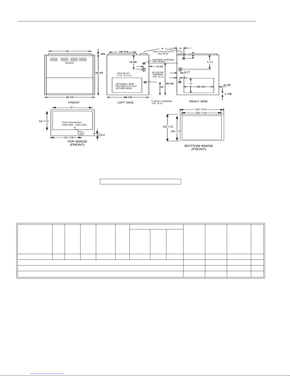
NOTE: Vent must be increased to 5” using adapter provided.
All dimensions are in inches and are approximate.
FIGURE 1 : DIMENSIONS
Blower
Model
Input
MBH
Output
MBH
AFUE
*
Air Temp
Rise °
Max.
Outlet
Temp.
F
°
F
HP Nomi-
nal
Motor
Amps
Size
Total
Unit
Amps
Max.
OverCurrent
Protect.
@230V
P4HUE30N13006 160 130 78 25 - 55 150 1-1/2 10 12 x 15 250
208/230 VAC (ONLY) 15 20 12
115 and 208/230 VAC (SPLIT) 6 & 11 15 12
115 VAC (ONLY)
‡
27 30 10
*. AFUE numbers are determined in accordance with DOE test procedures.
†. Wire size and overcurrent protection must comply with the National electric code (ANSI / NFPA-70-latest edition)
‡. Motor must be converted to 115 VAC operation
• For altitudes above 2,000 feet, reduce capacity 4% for each 1,000 ft. above sea level. Refer to form 650.74-N1.1V
• Wire size based on copper conductors, 60_ C, 3% voltage drop.
• See Replacement Parts list for LP gas and High Altitude conversion kits. External filter kits (bottom and side) are also available for
models above.
• Continuous return air t temperature must not be below 55°F (13°C)
Min. Wire
Size (AWG)
@ 75 Ft.
One Way
†
Oper.
Wgt.
(Lbs)
2 Unitary Products Group
Page 3

FIGURE 2 : FIELD WIRING DIAGRAMS
036-21166 -001 REV A (0201)
FIGURE 3 : FIELD WIRING DIAGRAMS
TABLE 1: FILTER SIZE / ADD-ON COOLING
MODEL NUMBER
P4HUE30N13006 5, 6, 7-1/2 3318 250
*. ESP (External Static Pressure) .75” W.C. is at furnace outlet ahead of cooling coil
Unitary Products Group 3
ADD-ON COOLING
TONS
CFM @ .80 ESP
*
@ 230
APPROX. OPER.
WEIGHT
Page 4

036-21166 -001 REV A (0201)
FIGURE 4 : TYPICAL HEATING & COOLING CONTROL CONNECTIONS
FIGURE 5 : TYPICAL HEATING & COOLING CONNECTIONS: IF A/C UNIT IS TRANSFORMER EQUIPPED
FIGURE 6 : TYPICAL HEATING & COOLING CONNECTIONS: IF THERMOSTAT IS EQUIPPED WITH SEPARATE R
AND RC CONTACTS
H
4 Unitary Products Group
Page 5

TABLE 2:
036-21166 -001 REV A (0201)
BLOWER PERFORMANCE SCFM - UPFLOW / HORIZONTAL (WITHOUT FILTER)
Note: Data below reflects airflows with bottom return opening
VOLTAGE
230 VAC
TABLE 3:
VOLTAGE
208 VAC
+
NOTE:
MOTOR
PULLEY
TURNS
Closed
0.30 040 0.50 0.60 0.70 0.80 0.90 1.00
EXTERNAL
+++ +
STATIC PRESSURE, INCHES, W.C
3467 3318 3163 2950
1 Open 3820 3687 3550 3406 3240 3066 2846 2589
2 Open 3575 3433 3269 3096 2913 2700 2449 2049
3 Open 3375 3205 2996 2807 2585 2293
4 Open 2805 2715 2570 2351 2017
MOTOR
PULLEY
TURNS
Closed
0.30 040 0.50 0.60 0.70 0.80 0.90 1.00
EXTERNAL
+++ +
STATIC PRESSURE, INCHES, W.C
3383 3242 3100 2890
1 Open 3674 3555 3423 3283 3144 2990 2789 2555
2 Open 3543 3379 3213 3055 2888 2673 2420
3 Open 3375 3210 3035 2850 2633 23343
4 Open 3100 2919 2708 2498 2226
Operation at these conditions will cause motor overload.
Operation in the shaded area may cause excessive furnace temperature rise.
Airflow is expressed in standard cubic feet per minute.
.
1860 1026
1307 -- --
.
1804
1889 --
1724 -- --
TABLE 4: UNIT CLEARANCES TO COMBUSTIBLES (ALL SURFACES IDENTIFIED WITH THE UNIT IN A
VERTICAL POSITION
RIGHT
APPLICATION TOP FRONT REAR
UPFLOW 1 6 0 0 3 6 COMBUSTIBLE YES YES YES NO
UPFLOW B-VENT 1 3 0 0 0 1 COMBUSTIBLE YES YES YES NO
HORIZONTAL 1 6 0 0 3 6 COMBUSTIBLE NO YES YES YES (SEE NOTE)
HORIZ. B-VENT 1 3 0 0 0 1 COMBUSTIBLE NO YES YES YES (SEE NOTE)
LEFT
SIDE
SIDE
FLUE FLOOR
NOTE: Line contact only permitted between lines formed by the intersection of the rear panel and side panel (top in horizontal position) of the
furnace jacket and building joists, studs or framing.
Unitary Products Group 5
/
BOTTOM CLOSET ALCOVE ATTIC LINE CONTACT
Page 6

036-21166 -001 REV A (0201)
ACCESSORIES
Propane Conversion Kit - INP0349
This accessory conversio n kit may be used to convert nat ural
gas units for propane (LP) operation. Conversion should be
made by qualified distributor or dealer personnel.
High Altitude pressure switch kits - 1PS0301
This accessory kit may be used to convert units for high altitude operation. Conversion must be made by a qualified distributor or dealer personnel. Please see form 650.74-N1.1V
for detailed instructions.
External Bottom Filter Rack or Horizontal End Return 1BR0332
Application of “High Velocity” rack provides opening for (2)
16” x 19-1/2” filters (not supplied). Attached to the end of the
furnace and provides duct flange s. Wil l acc ept up to 2” filters .
External Side Return Filter Rack - ISR0302
Provides a 16 x 25 cleanable, high velocity type filter and
attaches to the furnace side panel and the return air duct.
The filter is easily replaced. Package contains six filter racks
with filters.
Furnace Twinning Control - (2TC0300124)
This twinning control accessory allows proper operation of
two furnaces when the units are installed on a a common
duct system in a commercial application. This allows a
greater system cfm and heating capacity to be attained than
would be available from a single furnace. Belt drive furnace
also requires application of an
Accessory Sensor Kit
2T03700106.
-
6 Unitary Products Group
Page 7

036-21166 -001 REV A (0201)
Unitary Products Group 7
Page 8

Subject to change without notice. Printed in U.S.A. CD: 6-21142 036-21166 -001 REV A (0201)
Copyright © by Unitary Products Group 2001. All rights reserved. Supersedes: Nothing
Unitary 5005 Norman
Products York OK
Group Drive 73069
 Loading...