

Page 1
TECHNICAL GUIDE
A
®
MODULAR PSC AIR HANDLERS
5154297-CTG-C-0216
DESCRIPTION
This fan coil line offers the ultimate in application flexibility. This
unit may be used for upflow, downflow, horizontal right, or
horizontal left applications.
All JCI Unitary Products air handlers and coils can use a TXV to
provide our customers with the optimum performance and
refrigerant control. Single piece air handlers are available with
“Flex-coils” (without a factory installed metering device). For
added flexibility, an R-22 or R-410A TXV or piston must be field
installed to meet the requirement of the desired refrigerant.
Some coil models available with factory installed TXV.
FOR USE WITH SPLIT-SYSTEM
COOLING & HEAT PUMPS
MODELS: MP - 115V SERIES
Due to continuous product improvement,
specifications are subject to change without notice.
Visit us on the web at:
www.upgnet.com and www.colemanac.com
dditional rating information can be found at:
www.ahridirectory.org
FEATURES
COMMON MP AIR HANDLER AND CM COIL FEATURES
2
RC
- Rigid Case Construction interior endoskeleton for
structural support, smooth side, and locks in insulation.
Powder-painted - G30 galvanized steel case provide a coated
edge that resists corrosion and rust creep.
Quality Construction - Structural components are made of
Aluminum or G90 galvanized steel to prevent corrosion.
Improved Insulation Design - Single piece with no external
screws to reduce thermal transmission paths to prevent
sweating. Foil faced insulation for ease of cleaning.
Case Depth - These models have 20.5” casing which provide
ease of attic access and tight applications.
MP AIR HANDLERS
Factory Sealed - Achieves 2% or less total airflow leakage rate
at duct leakage test conditions in positive and negative
pressure for system airflow verification.
Blowers - All models use direct-drive, multi-speed PSC motors.
CM COILS
MaxAlloyTM Coil - Long life aluminum coils built to deliver
lasting performance, efficiency and reliability.
Thermostatic Expansion Valve - The accessory chatleff style
TXV provides easy installation to convert the indoor coil to the
required refrigerant that does not require brazing to replace or
install. Some models are available with factory installed TXV.
Thermoset Drain Pan - Low retention and positive slope for
drainage to reduce potential mold or contaminants.
Accessories - A full line of matching accessories available for
use with the blower and coils to provide for any type of
application.
WARRANTY SUMMARY
Standard 5-year limited parts warranty.
Extended 10-year limited parts warranty when product is
registered online within 90 days of purchase for replacement
or closing for new home construction.
FOR DISTRIBUTION USE ONLY - NOT TO BE USED AT POINT OF RETAIL SALE
Page 2
5154297-CTG-C-0216
LIST OF SECTIONS
DESCRIPTION . . . . . . . . . . . . . . . . . . . . . . . . . . . . . . . . . . . . . . . . . . 1
FEATURES . . . . . . . . . . . . . . . . . . . . . . . . . . . . . . . . . . . . . . . . . . . . 1
MP AIR HANDLERS . . . . . . . . . . . . . . . . . . . . . . . . . . . . . . . . . . . . . 1
CM COILS . . . . . . . . . . . . . . . . . . . . . . . . . . . . . . . . . . . . . . . . . . . . . 1
WIRING DIAGRAM 9NOMENCLATURE . . . . . . . . . . . . . . . . . . . . . 2
DIMENSIONS & DUCT CONNECTION DIMENSIONS . . . . . . . . . . . 3
DIMENSIONS - MP MODULAR AIR HANDLERS &
8CM MULTI-POSITION FULL CASED COILS . . . . . . . . . . . . . . . . . 3
COOLING CAPACITY . . . . . . . . . . . . . . . . . . . . . . . . . . . . . . . . . . . . 4
PHYSICAL & ELECTRICAL DATA - COOLING ONLY . . . . . . . . . . 5
ELECTRICAL DATA - COOLING ONLY . . . . . . . . . . . . . . . . . . . . . . 5
POWER WIRING - LINE CONNECTIONS . . . . . . . . . . . . . . . . . . . . 6
BLOWER SPEED CONNECTIONS . . . . . . . . . . . . . . . . . . . . . . . . . . 6
LIMITATIONS . . . . . . . . . . . . . . . . . . . . . . . . . . . . . . . . . . . . . . . . . . 6
TYPICAL APPLICATIONS . . . . . . . . . . . . . . . . . . . . . . . . . . . . . . . . 6
TYPICAL THERMOSTAT CONNECTION . . . . . . . . . . . . . . . . . . . . . 6
ACCESSORIES . . . . . . . . . . . . . . . . . . . . . . . . . . . . . . . . . . . . . . . . . 7
FILTER RACK DIMENSIONS . . . . . . . . . . . . . . . . . . . . . . . . . . . . . . 7
AIR FLOW DATA - CFM . . . . . . . . . . . . . . . . . . . . . . . . . . . . . . . . . . 8
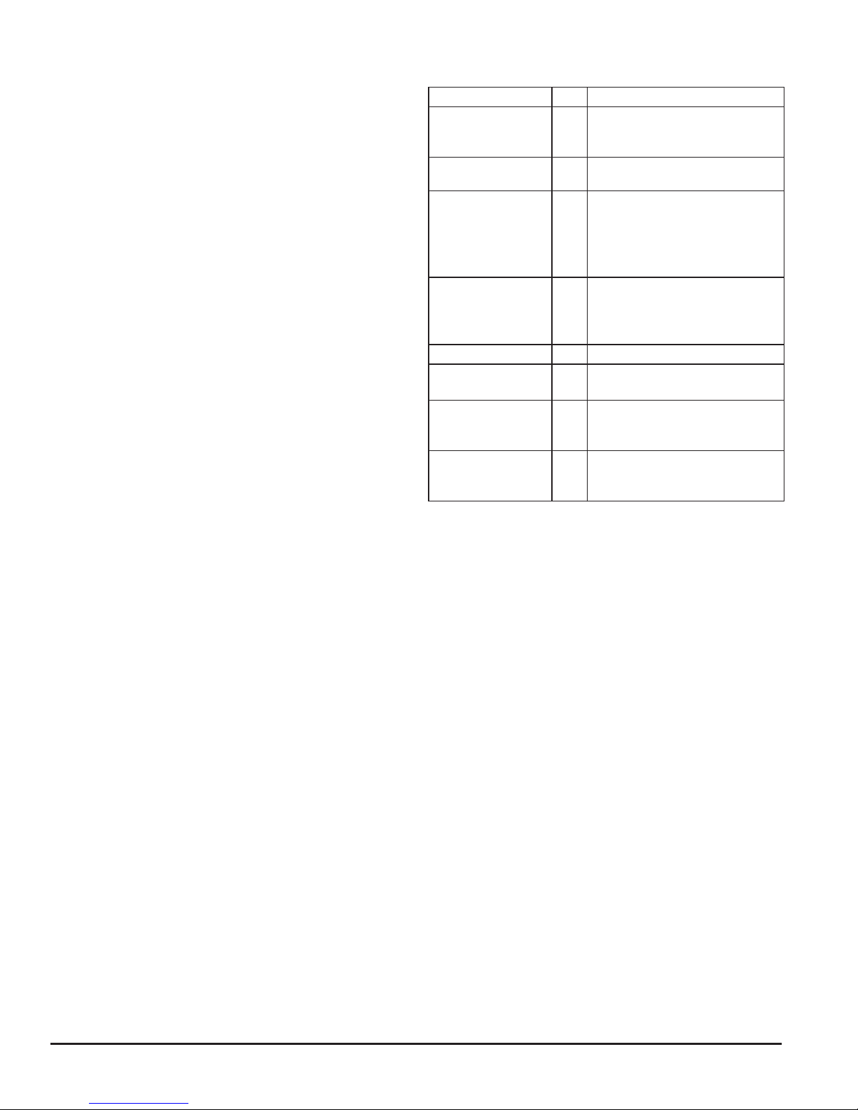
WIRING DIAGRAM 9
PRODUCT TYPE
POSITION
MOTOR TYPE
OPTIONS
NOMINAL
AIR FLOW
CABINET WIDTH
OPTIONS
VOLTAGE
(Voltage-Phase-Hertz)
GENERATION
(MAJOR REVISION)
STYLE LETTER
(MINOR REVISION)
NOT USED FOR
ORDERING
NOMENCLATURE
M = Modular Blower
M
P = Multi PSC
E = Multi Std ECM
P
V = Multi VS ECM
C = Communications Ready
-
- (No Designator) = Standard (No Options)
08 = 800 CFM
12 = 1,200 CFM
12
14 = 1,400 CFM
16 = 1,600 CFM
20 = 2,000 CFM
A = 14.5"
B = 17.5"
B
C = 21.0"
D = 24.5"
N = No options
N
1 = 115-1-60
1
2 = 208/230-1-60
1 = 1st Gen
2 = 2nd Gen
1
etc.
A = Style A
B = Style B
A
etc.
3 = 208/230-3-60
4 = 460-3-60
2 Johnson Controls Unitary Products
Page 3
5154297-CTG-C-0216
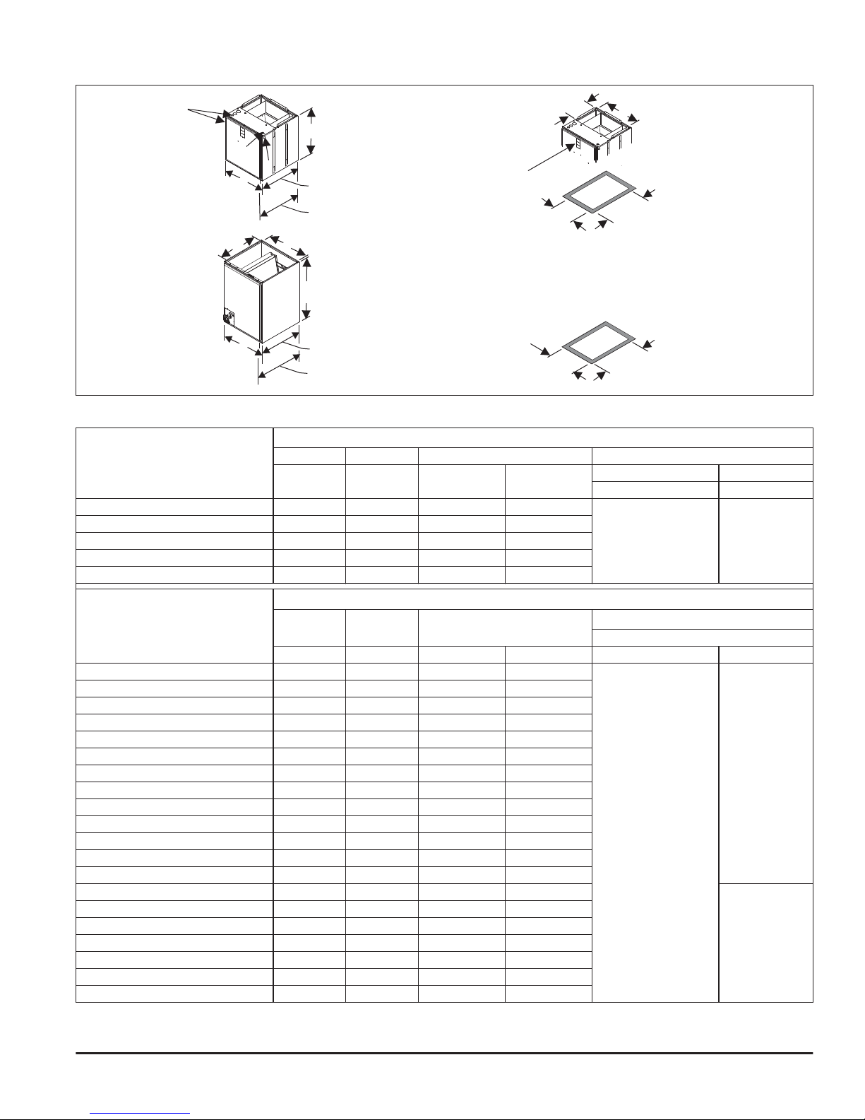
DIMENSIONS & DUCT CONNECTION DIMENSIONS
E
AIR HANDLER
(OPENING)
COIL
19-1/8”
A
F
F
B
B
20-1/2”
21-1/2”
C (OPENING)
A
20-1/2”
21-1/2”
SERVICE DISCONNECT
PANEL
12-3/16”
C (OPENING)
BOTTOM OPENING
D (OPENING)
D
BOTTOM INLET
19-1/8”
DIMENSIONS
19-1/8”
TOP OUTLET
DIMENSIONS
DIMENSIONS
DIMENSIONS - MP MODULAR AIR HANDLERS & CM MULTI-POSITION FULL CASED COILS
Dimensions
Models
Height Width Opening Widths Wiring Knockouts
AB C D
MP08BN11 21-1/2 17-1/2 16-1/2 16-1/2
MP12BN11 21-1/2 17-1/2 16-1/2 16-1/2
MP14DN11 22-1/2 24-1/2 23-1/2 23-1/2
MP16CN11 22-1/2 21 20 20
MP20DN11 22-1/2 24-1/2 23-1/2 23-1/2
Dimensions
Models
Height Width Opening Widths
A B C D Liquid Vapor
CM18A 19-1/2 14-1/2 13-1/2 13-1/2
CM18B 19 17-1/2 16-1/2 16-1/2
CM24A 19-1/2 14-1/2 13-1/2 13-1/2
CM24B 19 17-1/2 16-1/2 16-1/2
CM24C 21 21 20 20
CM30A 25-1/2 14-1/2 13-1/2 13-1/2
CM30B 23 17-1/2 16-1/2 16-1/2
CM30C 23 21 20 20
CM30D 25 24/1/2 23-1/2 23-1/2
CM36A 25-1/2 14-1/2 13-1/2 13-1/2
CM36B 25-5/8 17-1/2 16-1/2 16-1/2
CM36C 25 21 20 20
CM36D 25 24-1/2 23-1/2 23-1/2
CM42C 27 21 20 20
CM42D 27 24-1/2 23-1/2 23-1/2
CM48C 33 21 20 20
CM48D 32-3/4 24-1/2 23-1/2 23-1/2
CM60C 33 21 20 20
CM60D 32-3/4 24-1/2 23-1/2 23-1/2
CM64D 32-3/4 24-1/2 23-1/2 23-1/2
1. All dimensions are in inches as actual size (Dimensions in parenthesis are Conduit size).
2. Refrigerant line sizes may require larger lines for extended line lengths. See Application Data part number 247077.
1
EF
Power Control
7/8 (1/2),
1-3/8 (1),
1-23/32 (1-1/4)
1
Refrigerant Connections
3/8
A0452-002
7/8 (1/2)
2
Line Size
3/4
7/8
Johnson Controls Unitary Products 3
Page 4

5154297-CTG-C-0216
COOLING CAPACITY1
Models
CM18B 600
CM24B 800
CM24C 800
CM30B 1000
CM30C 1000
CM30D 1000
CM36B 1000
CM36B 1200
CM42C 1200
CM36C 1200
CM36D 1200
CM42C 1400
CM42D 1400
For notes, see Page 5.
Rated CFM
Entering Air
2
Dry/Wet Bulb (°F)
MBH@ Evap. Temp. and Corresponding R-410A Pressure (°F/PSIG)
35/107.9 40/118.9 45/130.7 50/143.3
85/72 45.7 41.6 36.8 30.5
80/67 38.5 33.9 28.5 22.3
75/62 31.5 26.5 20.5 15.9
70/57 24.4 19.5 15.2 11.5
85/72 52.2 47.5 41.8 35.0
80/67 43.6 38.3 31.9 24.5
75/62 35.2 29.5 22.7 16.2
70/57 27.1 20.7 15.5 11.4
85/72 52.2 47.5 41.8 35.0
80/67 43.6 38.3 31.9 24.5
75/62 35.2 29.5 22.7 16.2
70/57 27.1 20.7 15.5 11.4
85/72 75.3 67.8 56.8 47.1
80/67 62.6 54.6 44.2 34.5
75/62 50.2 41.3 32.0 22.9
70/57 37.8 30.1 21.5 16.2
85/72 75.3 67.8 56.8 47.1
80/67 62.6 54.6 44.2 34.5
75/62 50.2 41.3 32.0 22.9
70/57 37.8 30.1 21.5 16.2
85/72 75.3 67.8 56.8 47.1
80/67 62.6 54.6 44.2 34.5
75/62 50.2 41.3 32.0 22.9
70/57 37.8 30.1 21.5 16.2
85/72 82.1 73.7 64.1 54.4
80/67 68.6 60.1 50.5 39.5
75/62 56.3 47.0 37.3 29.2
70/57 43.5 36.0 28.3 21.6
85/72 91.6 82.4 71.3 59.4
80/67 76.5 65.4 54.6 42.8
75/62 61.3 51.2 40.0 30.5
70/57 47.5 38.1 28.7 22.3
85/72 98.0 88.6 77.4 66.4
80/67 82.6 72.6 61.7 50.6
75/62 68.5 57.6 47.5 36.6
70/57 53.9 44.8 35.0 28.4
85/72 91.6 82.4 71.3 59.4
80/67 76.5 65.4 54.6 42.8
75/62 61.3 51.2 40.0 30.5
70/57 47.5 38.1 28.7 22.3
85/72 91.6 82.4 71.3 59.4
80/67 76.5 65.4 54.6 42.8
75/62 61.3 51.2 40.0 30.5
70/57 47.5 38.1 28.7 22.3
85/72 100.6 89.8 78.2 64.7
80/67 83.5 73.7 59.8 48.0
75/62 67.8 55.8 44.7 32.5
70/57 52.3 41.5 30.7 23.7
85/72 100.6 89.8 78.2 64.7
80/67 83.5 73.7 59.8 48.0
75/62 67.8 55.8 44.7 32.5
70/57 52.3 41.5 30.7 23.7
4 Johnson Controls Unitary Products
Page 5

5154297-CTG-C-0216
COOLING CAPACITY1 (Continued)
Models
Rated CFM
Entering Air
2
Dry/Wet Bulb (°F)
MBH@ Evap. Temp. and Corresponding R-410A Pressure (°F/PSIG)
35/107.9 40/118.9 45/130.7 50/143.3
85/72 108.0 98.4 88.1 73.8
CM48C 1400
80/67 93.3 82.1 69.7 57.0
75/62 75.9 64.4 53.1 41.9
70/57 60.7 49.9 39.4 32.4
85/72 115.2 105.0 93.9 79.0
CM48C 1600
80/67 88.3 78.2 65.5 52.6
75/62 72.7 60.8 50.1 37.6
70/57 57.7 46.9 36.6 29.7
85/72 115.2 105.0 93.9 79.0
CM48D 1600
80/67 88.3 78.2 65.5 52.6
75/62 72.7 60.8 50.1 37.6
70/57 57.7 46.9 36.6 29.7
85/72 115.1 103.0 91.7 78.6
CM60C 1800
80/67 96.8 85.9 73.7 60.5
75/62 80.7 69.4 57.5 43.5
70/57 58.7 48.9 37.7 32.7
85/72 115.1 103.0 91.7 78.6
CM60D 1800
80/67 96.8 85.9 73.7 60.5
75/62 80.7 69.4 57.5 43.5
70/57 58.7 48.9 37.7 32.7
85/72 133.6 118.5 103.2 86.6
CM64D 1800
80/67 111.4 96.2 80.3 62.8
75/62 90.7 75.1 60.0 43.5
70/57 70.6 56.9 42.5 32.8
1. See Condensing Unit or Heat Pump Technical Guide for Total Cooling Capacity and Sensible Capacity.
2. Airflow is calculated for each system tonnage.
PHYSICAL & ELECTRICAL DATA - COOLING ONLY
Models MP08B MP12B MP14D MP16C MP20D
Blower - Diameter x Width 10 x 8 10 x 8 10 x 10 10 x 10 10 x 10
Motor
HP 1/4 HP 1/2 HP 3/4 HP 1/2 HP 1 HP
Nominal RPM 1075 1085 1085 1075 1007
Voltage 115 115 115 115 115
Full Load Amps @115V 2.8 5.0 6.3 6.3 9.0
Type DISPOSABLE OR PERMANENT
Filter
1
Size 16 x 20 x 1 16 x 20 x 1 22 x 20 x 1 20 x 20 x 1 22 x 20 x 1
Bottom Rack Kit 1BR01117 1BR01117 1BR01124 1BR01121 1BR01124
Permanent Type Kit 1PF0601 1PF0601 1PF0603 1PF0602 1PF0603
Shipping / Operating Weight (lbs.) 52/51 52/51 75/74 68/67 75/74
1. Field Supplied.
ELECTRICAL DATA - COOLING ONLY
Models
Motor FLA
1
Minimum Circuit Ampacity
MP08B 2.8 3.5
MP12B 5.0 6.3
MP14D 6.3 7.9
MP16C 6.3 7.9
MP20D 9.0 11.3
1. FLA = Full Load Amps.
2. MOP = Maximum Overcurrent Protection device; must be HACR type circuit breaker or time delay fuse. Refer to the latest edition of the National Electric Code or
in Canada the Canadian electrical Code and local codes to determine correct wire sizing.
MOP
15
2
Johnson Controls Unitary Products 5
Page 6

5154297-CTG-C-0216
POWER WIRING - LINE CONNECTIONS
NO ELECTRIC HEAT
GND
.
POWER
SUPPLY
CN
CN
COMPONENT CODES
CKT - CIRCUIT
CN - WIRE CONNECTOR/NUT
GND - GROUND LUG
FIELD POWER WIRING
(110V/120V)
A0459-001
BLOWER SPEED CONNECTIONS
PSC STANDARD MOTOR
FACTORY WIRED TO
FAN MOTOR RELAY
TERMINAL ON
CONTROL BOARD
PRP
FACTORY WIRED TO
TRANSFORMER
ALTERNATE CONNECTION
FOR MP20
CAP
RC
PRP
BRN
BLK
H M L
115 VOLT
BLOWER
MOTOR
GND.
PSC STANDARD MOTOR
FACTORY WIRED TO
FAN MOTOR RELAY
TERMINAL ON
CONTROL BOARD
115 VOLT
BLOWER MOTOR
ALL OTHER AIR HANDLERS
FACTORY WIRED TO
TRANSFORMER
CAP
HIGH
MED
BLK
LOW
BRN
A0460-001
PUR
PUR
GND.
LIMITATIONS
These units must be wired and installed in accordance with all
national and local safety codes.
Voltage limits are as follows:
Air Handler Voltage
110-120-1-60 110-120
1. Rated in accordance with ARI Standard 110, utilization range “A”.
1
Normal Operating Voltage Range
Airflow must be within the minimum and maximum limits
approved for electric heat, evaporator coils and outdoor units.
TYPICAL APPLICATIONS
UPFLOW
DOWNFLOW
HORIZONTAL RIGHT
HEAT
HORIZONTAL LEFT
A0458-001
TYPICAL THERMOSTAT CONNECTION
AIR
AIR
THERMOSTAT
R
GG
C
HANDLER
RED
R
GRN
BLU
C
Y
COOLING ONLY
CONDENSING
UNIT
C
Y
THERMOSTAT
R
G
C
HANDLER
RED
R
GRN
G
BLU
C
O
Y
X/L
SINGLE STAGE HEAT PUMP
6 Johnson Controls Unitary Products
HEAT
PUMP
R
W
W1/66
C
O
Y
X/L
A0461-001
Page 7

5154297-CTG-C-0216
ACCESSORIES
Refer to Price Manual for specific model numbers where not
shown.
TXV Kits - “Flex-coils” are shipped without a factory installed
metering device. For added flexibility, an R-22 or R-410A TXV
or piston must be field installed to meet your refrigerant choice.
All kits are chatleff style and require no brazing to install.
Breaker Moisture Seal Accessory - A clear circuit breaker
moisture barrier seals the breakers from humidity and dust. The
flexibility of the clear cover allows circuit breakers to be turned
ON or OFF without removing the cover. The cover firmly
attaches to the access panel around the circuit breakers with
the use of double backed adhesive tape. To ensure that
moisture or dust does not contaminate circuit breakers, an S102435672000, Circuit Breaker, Cover Seal may be ordered.
Bottom Rack Filter Kit - The filter frame accessory allows
installation of an external air handler filter in an upflow
application, a downflow application, or a horizontal application
(refer to the following illustration/table for Filter Rack
Dimensions).
Thermostat - Compatible thermostat controls are available
through accessory sourcing. For optimum performance, these
outdoor units are fully compatible with our Coleman touch
screen thermostat with proprietary (patent-pending) hexagon
interface. For more information, see the thermostat section of
the Product Equipment Catalog.
FILTER RACK DIMENSIONS
A
E
C
D
Galvanized
Models
1BR01117
1BR01121
1BR01124
Note: Filters - Not supplied with kit.
A B C D E Filer Size
17.50 21.56 4.00 18.63 14.25 16 x 20 x 1 or 2
21.00 21.56 4.00 18.63 17.75 20 x 20 x 1 or 2
24.50 21.56 4.00 18.63 21.25 20 x 24 x 1 or 2
SIDE
TRACKS
B
11/16
A0146-003
Johnson Controls Unitary Products 7
Page 8

AIR FLOW DATA - CFM
1
Models CM Models
CM18B
MP08B
CM24B
CM30B
MP12B
CM36B
CM30D
MP14D
MP16C
MP20D
1. Air handler units have been tested to UL 1995 / CSA 22.2 standards up to 0.50" wc. external static pressure.
Dry coil conditions only, tested without filters.
For optimal performance, external static pressures of 0.2" to 0.5" are recommended. Applications above 0.5" are not recommended.
CM36D
CM42D
CM36C
CM42C
CM48C
CM42D
CM48D
CM60D
CM64D
Blower
Motor Speed
High 1142 1126 1093 1057 1009 953 852
Medium 855 840 826 798 756 696 594
Low 676 663 638 584 528 482 404
High 1105 1088 1060 1030 987 948 859
Medium 825 815 802 780 752 678 591
Low 655 636 616 569 504 467 345
High 1521 1471 1397 1322 1241 1161 1057
Medium 1369 1329 1281 1224 1166 1092 1015
Low 1130 1107 1071 1029 972 910 842
High 1557 1507 1440 1363 1289 1185 1125
Medium 1351 1321 1266 1207 1153 1076 1019
Low 1103 1083 1056 1024 976 928 851
High 2092 2038 1958 1884 1795 1714 1591
Medium 1725 1697 1634 1598 1534 1454 1179
Low 1374 1366 1339 1316 1250 1070 904
High 2099 2040 1980 1903 1814 1680 1605
Medium 1725 1694 1652 1605 1541 1467 1182
Low 1388 1372 1340 1306 1277 1106 1026
High 2083 2033 1960 1894 1820 1720 1459
Medium 1690 1662 1623 1587 1534 1460 1233
Low 1399 1393 1370 1338 1269 1159 1073
High 1850 1785 1705 1625 1541 1373 1242
Medium 1693 1642 1574 1499 1378 1261 1145
Low 1512 1465 1407 1324 1225 1101 1022
High 1815 1754 1680 1593 1472 1278 1206
Medium 1670 1613 1554 1473 1311 1210 1082
Low 1488 1445 1376 1259 1181 1056 979
High 1886 1818 1739 1646 1567 1348 1163
Medium 1742 1683 1622 1538 1461 1237 1121
Low 1563 1512 1455 1399 1234 1086 1019
High 2123 2076 2001 1926 1840 1744 1439
Medium 1999 1959 1896 1821 1744 1651 1347
Low 1851 1819 1768 1698 1626 1544 1269
High 2178 2107 2034 1953 1878 1775 1604
Medium 2014 1965 1905 1843 1761 1660 1351
Low 1867 1832 1779 1727 1661 1544 1280
High 2132 2052 1993 1899 1813 1733 1594
Medium 1985 1941 1872 1798 1729 1648 1507
Low 1848 1810 1758 1695 1627 1548 1355
High 2069 2011 1929 1848 1755 1651 1402
Medium 1962 1902 1832 1758 1675 1558 1335
Low 1833 1787 1734 1667 1581 1382 1269
0.10 0.20 0.30 0.40 0.50 0.60 0.70
External Static Pressure (in. wc.)
Subject to change without notice. Published in U.S.A. 5154297-CTG-C-0216
Copyright © 2016 by Johnson Controls, Inc. All rights reserved. Supersedes: 5154297-CTG-B-1015
York International Corp.
5005 Y ork Drive
Norman, OK 73069
 Loading...