

Page 1
INSTALLATION, OPERATION AND
MAINTENANCE INSTRUCTIONS
FOR
230/240 VAC, 1ø, 50Hz
MACH 9 RV ROOF TOP AIR CONDITIONER /
HEAT PUMP AND REMOTE CONTROLLER
P/N: 1980-040 01-12-2016
RV Products Division
TABLE OF CONTENTS
I.
General Information 2
II.
Heat Pump Sizing 2
III.
Selecting an Installation Location 2
I V.
Installing the Roof Top Unit 2
V.
Securing the Heat Pump to the
Roof
4
VI.
Electrical Wiring 4
VII.
System Wiring Diagram 5
VIII.
Installing the 9430A451 Ceiling
Assembly
6
IX.
Operation and Maintenance 8
i.
Model & Serial Numbers 8
ii.
Operating Guidelines 8
iii.
Adjusting the Air Flow 8
iv.
Hand Held Controller 8
v.
Initial Conguration of the Hand Held
Controller
8
vi.
Selecting the Manual Mode of
Operation
8
vii.
Follow Me 10
viii.
Fahrenheit or Celsius (F/C) 10
ix.
Time and Day Set Up 10
x.
7-Day Programming 10
xi.
LED Lights & Buttons on Ceiling
Assembly
11
xii.
Routine Maintenance 11
xiii.
Warranty 11
SERVICE CONTACT:
Coast RV Pty Ltd.
PO BOX 6287 • SILVERWATER NSW 1811 Australia
Tel: +61-2-9645 7600 • technical@coastrv.com.au
Page 2

2
These instructions are a general guide for installing the
MACH 9, 230/240 VAC 50Hz Coleman-Mach roof top
heat pumps. For specic heat pump details, it will be
necessary to refer to ALL printed documents supplied
with this conditioner.
IMPORTANT NOTICE
These instructions are for the use of qualied
individuals specially trained and experienced in
installation of this type equipment and related system
components.
Installation and service personnel are required
by some states to be licensed. PERSONS NOT
QUALIFIED SHALL NOT INSTALL NOR SERVICE
THIS EQUIPMENT.
NOTE: The words “Shall” or “Must” indicate a
requirement which is essential to satisfactory and safe
product performance. The words “Should” or “May”
indicate a recommendation or advice which is not
essential and not required but which may be useful or
helpful.
WARNING! – SHOCK HAZARD To prevent the
possibility of severe personal injury or equipment
damage due to electrical shock, always be sure
the electrical power source to the appliance is
disconnected.
CAREFULLY FOLLOW ALL INSTRUCTIONS AND
WARNINGS IN THIS BOOKLET TO AVOID DAMAGE
TO THE EQUIPMENT, PERSONAL INJURY OR FIRE.
WARNING! Improper installation may damage
equipment, can create a hazard and will void the
warranty.
The use of components not tested in accordance
with these units will void the warranty, may make the
equipment in violation of state codes, may create a
hazard and may ruin the equipment.
SAFETY WARNING! This appliance is not
intended for use by young children or inrm persons
unless they have been adequately supervised by
a responsible person to ensure they can use the
appliance safely.
I. GENERAL INFORMATION
OEM – Please make sure all documentation
accompanies the heat pump.
INSTALLER AND/OR DEALER – Please make sure all
documentation is presented to the product consumer.
INQUIRIES ABOUT THE A/C UNIT – Inquiries to your
Airxcel, Inc. representative or to Airxcel, Inc. pertaining
to product installation should contain both the model
and serial numbers of the roof top unit. These rooftop
heat pumps have model and serial number identication
in two locations; (1) Rating Plate sticker - may be
viewed by removing the upper unit outer plastic shroud,
(2) Model/Serial number sticker (silver color) - located
on the return air section of the basepan of the roof
top unit. Additionally, if the heat pump is installed, the
Manufacturer and Model Number may be viewed from
the rear at the center of the basepan under the plastic
shroud.
II. HEAT PUMP SIZING
The ability of a heat pump in the cooling mode to cool
a vehicle or maintain a consumer desired temperature
is dependent on the heat gain of the vehicle. The
physical size, the window area, the quality and amount
of insulation, the exposure to sunlight, the number of
people using the vehicle and the outside temperature,
may increase the heat gain such that the capacity of the
air conditioner is exceeded.
As a general rule, air supplied (discharge air) in the
cooling mode will be 15 to 20 degrees F. (8 to 12
degrees C) cooler than the air entering (return air) the
ceiling assembly bottom air grilles.
For example, if the air entering the heat pump is 80
degrees F. (27 degrees C) (return air), the supply air
(discharge air) into the vehicle will be 60 to 65 degrees
F. (15 to 19 degrees C). As long as this temperature
difference (15 to 20 degrees F, 8 to 12 degrees C) is
being maintained, the unit is operating properly.
Again, give careful consideration to the vehicle heat gain
variables. During extreme outdoor temperatures, the
heat gain of the vehicle may be reduced by:
• Parking the vehicle in a shaded area
• Keeping windows and doors closed
• Avoiding the use of heat producing appliances
• Using window shades (blinds and/or curtains)
For a more permanent solution to high heat gain
situations, additional vehicle insulation, window awnings
and/or window glass tinting should be considered.
III. SELECTING AN INSTALLATION LOCATION
Your Coleman-Mach heat pump has been designed for
use primarily in recreational vehicles.
Is the roof of the vehicle capable of supporting both the
roof top unit and ceiling assembly without additional
support structures? Inspect the interior ceiling mounting
area to avoid interference with existing structural
members such as: bunks, curtains, tracks or room
dividers. The depth of the ceiling assembly shroud is
51mm. Be sure to check clearance to doors which must
be swung open (refrigerator – closets - cabinets).
Most of the time, roof mount heat pumps are installed
at existing roof vent locations. If there is no roof vent
(existing mounting hole), the following placement
locations are recommended.
Motorhomes – a single unit or the forward of two
units should be mounted within 2.7m of the driver
compartment.
Travel Trailers or Mini-Homes – a location should be
selected that is near the door slightly forward of the
vehicle center length.
Vans – location should be in the center of the roof (side
to side – front to back).
Truck with Camper – location should be between
1.2 and 1.5m from the rear of the camper to achieve
maximum cooling effect.
IV. INSTALLING THE ROOF TOP UNIT
DANGER! SHOCK HAZARD DISCONNECT ALL
POWER TO THE VEHICLE BEFORE PERFORMING
ANY CUTTING TO THE VEHICLE. CONTACT WITH
HIGH VOLTAGE CAN RESULT IN EQUIPMENT
DAMAGE, PERSONAL INJURY OR DEATH.
Page 3
3
IMPORTANT
TO PREVENT DAMAGE TO THE WIRING AND
BATTERY, DISCONNECT THE BATTERY CABLE
FROM THE POSITIVE BATTERY TERMINAL BEFORE
PERFORMING ANY CUTTING TO THE VEHICLE.
Once the location for your heat pump has been
determined (See Section III), a reinforced and framed
roof hole opening must be provided (may use existing
vent hole). Before cutting into the vehicle roof, verify that
the cutting action will clear all structural members and
crossbeams. Additionally, the location of any inner roof
plumbing and electrical supplies must be considered.
A. If a roof vent is already present in the desired
mounting location for the heat pump, the following
steps must be taken.
1. Remove all screws which secure the roof vent to
the vehicle. Remove the vent and any additional
trim materials. Carefully remove all caulking from
around the roof opening to obtain clean exterior
roof surface.
2. It may be necessary to seal some of the old roof
vent mounting screw holes which may fall outside
of the heat pump basepan gasket.
3. Examine the roof opening. If the opening is
smaller than 356mm x 356mm, the opening must
be enlarged.
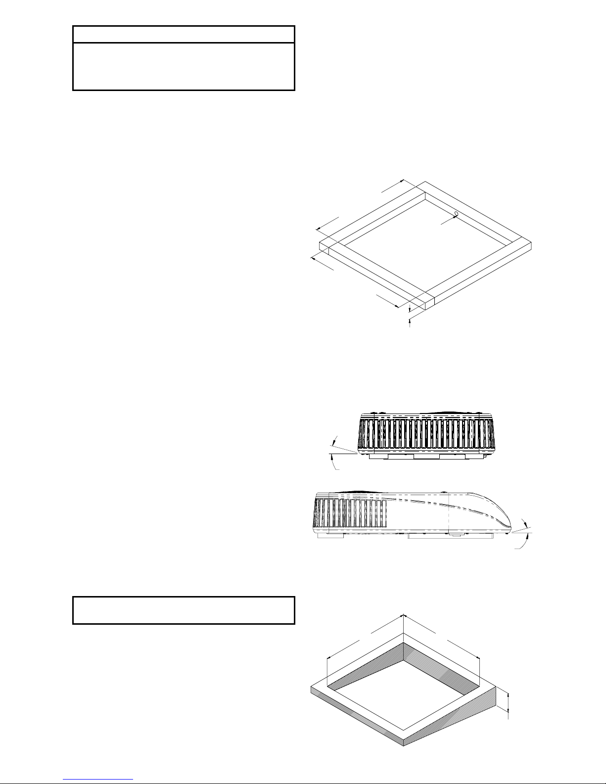
B. If a roof vent opening is not used, a new opening
(See Figure 1) will have to be cut into the vehicle
roof. A matching opening will also have to be cut
into the interior vehicle ceiling. If the ceiling opening
is carpeted, snagging could occur. After the opening
in the roof and interior ceiling are the correct size,
a framed support structure must be provided
between the exterior roof top and interior ceiling.
The reinforced framed structure must provide the
following guidelines:
1. Capable of supporting both the weight of the roof
top heat pump and the interior ceiling assembly.
2. Capable of holding or supporting the roof outer
surface and interior ceiling apart, so that when
the roof top heat pump and ceiling assembly are
bolted together, no collapsing occurs.
Airxcel, Inc. recommends that the spacing from the
vehicle roof top to the interior ceiling top be no less than
25mm. A typical support frame is shown in Figure 1.
The frame must provide an opening through the frame
to allow passage for the power supply wiring. Route the
supply wiring through the frame at the same time the
support frame is being installed.
C. The heat pump must be mounted as near level front
to rear and side to side as possible when the vehicle
is parked level. Figure 2 shows the maximum
allowable degree deviations.
IMPORTANT – Allow 600mm of supply wiring
through the support frame (working length).
After the support frame is installed, seal off all gaps
between the frame and both the roof exterior and the
supply wiring.
If the roof of the vehicle is sloped such that the heat
pump cannot be mounted within the maximum allowable
degree deviations, an exterior leveling shim will need to
be added to make the unit level. A typical front to back
leveling shim is shown in Figure 3.
Once the heat pump has been leveled, some additional
shimming may be required above the interior ceiling
assembly. The heat pump and the interior ceiling
assembly must have a squared installation relationship
before they are secured together.
D. After the mounting hole is properly prepared, remove
the carton and shipping pads from around the heat
pump. Carefully lift the unit to the top of the vehicle.
Do not use the outer plastic shroud for lifting. Place
the heat pump over the prepared mounting hole.
The pointed end (nose) of the shroud must face
towards the front of the vehicle. Pull down all loose
electrical connectors from the heat pump through
the mounting opening and let hang.
25 mm
MINIMUM
THICKNESS
356 to 381 mm
356 to 381 mm
HOLE FOR WIRES
TYPICAL ROOF OPENING
FIGURE 1
SIDE TO SIDE DEVIATION FRONT TO BACK DEVIATION
LEVEL TO 15° LEFT SIDE HIGH PERMISSIBLE LEVEL TO 15° NOSE HIGH PERMISSIBLE
FIGURE 2
HEIGHT VARIES
TO MAKE
UNIT LEVEL
356 mm
356 mm
FIGURE 3
Page 4
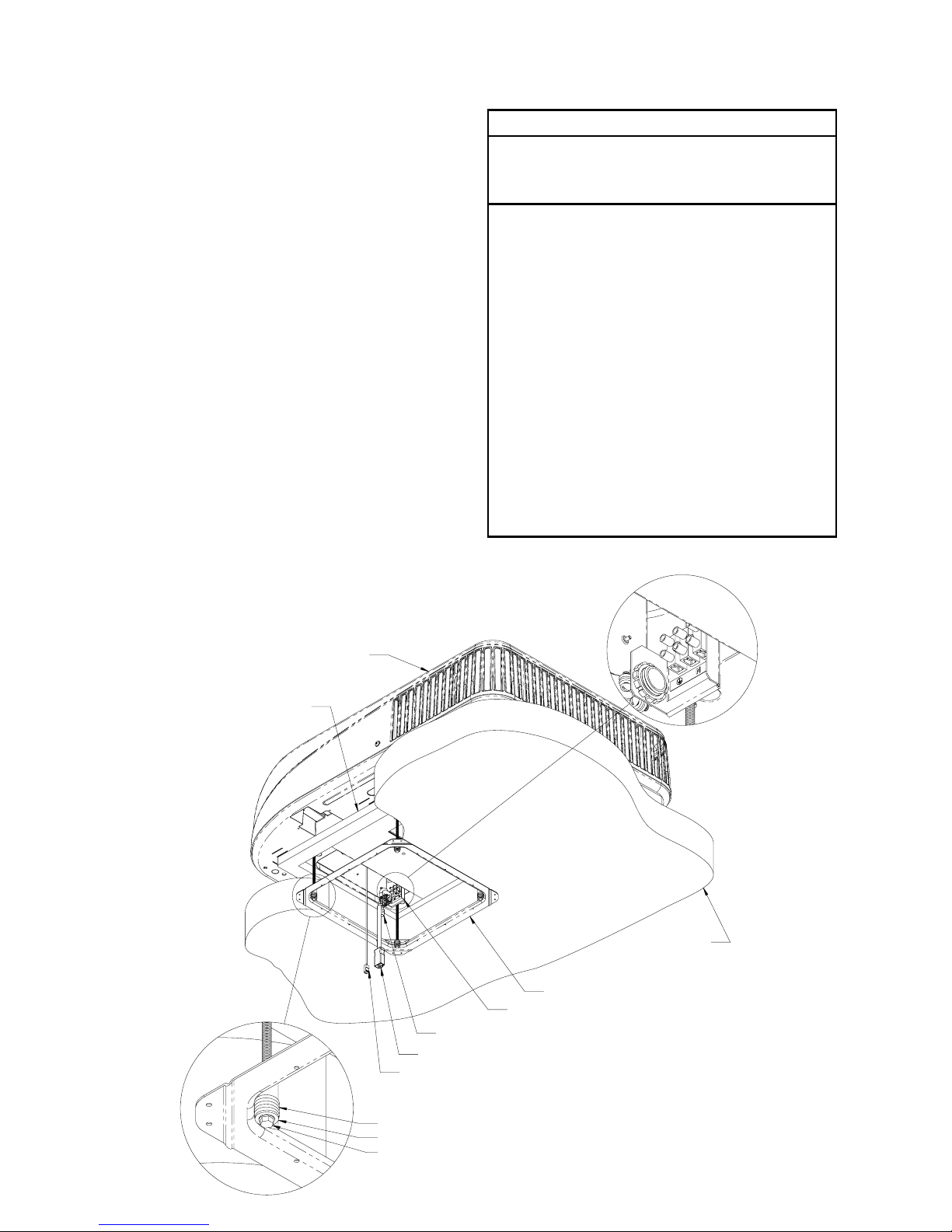
V. SECURING THE HEAT PUMP TO THE ROOF
A mounting frame is supplied with the ceiling assembly.
Follow the steps below to secure the heat pump to the
roof. Refer to Figure 4.
A. Locate the heat pump mount gasket over the 356mm to
381mm square opening in the roof.
B. Install the ceiling assembly mount frame using the
four bolts, washers and springs found with the ceiling
assembly.
C. Proper tension has been achieved for each bolt when
the spring coils have just come together (See Figure
4). The upper unit has now been properly installed with
optimum gasket compression.
D. If the heat pump is equipped with an optional evaporator
condensate pump, a 13 mm I.D. hose must be provided
that runs from the 356 mm square opening, through the
vehicle ceiling and down the side wall to allow water to
drain under the vehicle. The hose must not be allowed
to kink shut while making a bend. Connect the top end
of the drain hose to the barbed tting shown in Figure 4.
VI. ELECTRICAL WIRING
ROUTING 230/240 VAC Wiring - See Figure 4
Following high voltage wiring specications and all local
and national electrical codes, route the 230/240 VAC
supply wiring from its power source through the strain
relief and connect to the power strip. Tighten screws to
8 Kg-centimeters torque. Some OEM units are equipped
with a pre-wired power umbilical with plug which will
snap-lock into the OEM supplied mating part.
High Voltage Wiring Specications
Refer to most recent Australian/NZ Standard for Wiring
Rules
INSTALLER MUST PROVIDE A TWO POLE
DISCONNECT FOR ACTIVE AND NEUTRAL.
MAXIMUM OVERCURRENT PROTECTIVE DEVICE
FOR THESE UNITS: 15 AMPS
DANGER – SHOCK HAZARD!
MAKE SURE THAT ALL POWER SUPPLY TO THE UNIT IS
DISCONNECTED BEFORE PERFORMING ANY WORK ON
THE UNIT TO AVOID THE POSSIBILITY OF SHOCK INJURY
OR DAMAGE TO THE EQUIPMENT.
DANGER! - WHEN USING NON-METALLIC SHEATH
CABLES (ROMEX, ETC.), STRIP SHEATH BACK TO EXPOSE
100-150mm OF THE SUPPLY LEADS.
STRIP THE INDIVIDUAL WIRE LEAD ENDS FOR WIRE
CONNECTION (ABOUT 19mm BARE WIRE). INSERT THE
SUPPLY WIRES INTO THE ELECTRICAL CONNECTOR
CLAMP. SHEATH MUST PROTRUDE PAST THE CLAMP
BUSHING INSIDE THE BOX. MAKE SURE SHEATH CABLE
IS CENTERED IN CLAMP BEFORE TIGHTENING CLAMP ON
SHEATH CABLE!!
DO NOT OVER TIGHTEN!! THIS COULD RESULT IN
PINCHING THROUGH THE PLASTIC WIRE INSULATION
AND CAUSE SHORTING OR “HOT” WIRES TO GROUND
(SHOCK HAZARD). THE CLAMP IS INTENDED FOR STRAIN
RELIEF OF THE WIRES. SLIGHT PRESSURE IS USUALLY
SUFFICIENT TO ACCOMPLISH THIS.
IF OTHER THAN NON-METALLIC CABLES ARE USED FOR
SUPPLY CONDUCTORS, APPROPRIATE STRAIN RELIEF
CONNECTORS OR CLAMPS SHOULD BE USED.
IN NO CASE SHOULD CLAMPING OR PINCHING ACTION BE
APPLIED TO THE INDIVIDUAL SUPPLY LEADS (NEUTRAL
AND “HOT” WIRES).
ROOFTOP UNIT
MOUNTING GASKET
MOUNTING SPRING
CEILING ASSEMBLY PATCH CORD
FROM UPPER UNIT CONTROL
OPTIONAL POWER PLUG
OPTIONAL CONDENSATE DRAIN ADAPTER
POWER CONNECTION STRIP
MOUNTING FRAME
ROOF STRUCTURE
POWER CONNECTION STRIP
WITHOUT OPTIONAL POWER PLUG
WASHER
MOUNTING BOLT
FIGURE 4
4
Page 5

VII. SYSTEM WIRING DIAGRAM
5
BLOWER
MOTOR
FAN
MOTOR
WHT
ORNG
BLU
PUR
COMPR
YEL
BLK
RED
TERMINAL
BLOCK
1
BLK
C
S
R
OVERLOAD
COMPR.
RUN
CAPACITOR
FAN
CAPACITOR
BLOWER
CAPACITOR
BLU
RED
BLU
RED
WHT
RED
BLK
ORG
PUR
BLU
YEL
GRN
WHT
BLK
BLK
BLK
WHT
BLK
OPTIONAL COMPONENTS
AND WIRING
23
CONDENSATE
PUMP MOTOR
REVERSING
VALVE
SOLENOID
4
BRN
BLK
WHT
BLK
BLU
RED
L
N
-
+
OUT
AC
POWER
SUPPLY
WHT
BLK
3
1 EVAPORATOR
FREEZE SENSOR
2 OUTDOOR
FREEZE SENDOR
1
4
E N A
GRN/YEL
GND
COM
N.O
COMPRESSOR
RELAY
COM
REV. VALVE
RELAY
N.O
FAN
SWITCH
RELAY
FAN
SPEED
RELAY
FREEZE
B
-12
VDC
+12
VDC
R
WRW
FAN
HI LOW
LINE 2
HIGH VOLTAGE
SUPPLY WIRING
4 FOR THIS APPLICATION,
REMOVAL OF TAB IS NOT
REQUIRED.
YEL
PUR
BLK
RED
GRN/YEL
WHT
BLK
WHT
BLU
P.C. BOARD
BLACK
WHITE
GND
3 124
PATCH CORD
INDOOR
TEMPERATURE
SENSOR
IRC
RECEIVER
BOARD
AN
3 "W" CONNECTIONS
FOR FURNACE CONTROL
RES
2
(Fasten to middle
of mount frame)
Page 6

6
VIII. INSTALLING THE 9430A451 CEILING
ASSEMBLY (Refer to Figures 5 and 6)
NOTE: The following step by step instructions must
be performed in sequence to insure a quick and easy
installation.
A. Remove the grilles and lters from the ceiling
assembly shroud.
B. Locate the cloth duct assembly and attach to the
upper unit basepan with three of the provided short
screws.
C. Raise the ceiling assembly chute to align with the
cloth duct assembly. Attach the chute to the steel
mount frame with 4 short screws provided. Unfurl
the cloth duct to drop through the ceiling assembly
opening.
D. Gently peel off the release liner from the VHB (Very
High Bond) double sided tape. Press the cloth duct
uniformly around the perimeter of the opening to
adhere the cloth duct to the plastic chute. Carefully
trim the excess cloth duct (a razor knife is very
effective for this).
E. Plug in the room temperature sensor to the receptacle
on the ceiling assembly shroud. Raise the shroud
up near the mount frame and push the temperature
sensor up through the center opening of the air chute
and allow the sensor to hang over the side of the
chute. Plug in the patch cord from the upper unit to
the receptacle on the ceiling shroud as shown in the
magnied section of Figure 6.
F. Align the shroud with the air chute insuring that no
wires are trapped between plastic parts. Attach
the shroud to the steel frame with 4 short screws
provided.
G. Attach the room temperature sensor to a middle
hole of the steel mount frame using spacer, shoulder
washer, and #6 screw provided. Refer to Figure 5.
H. Replace the lters and retaining grilles. Using the
long screws provided, mount the hand held remote
control holster to an interior wall at a height of 24 cm.
in a location to prevent outlet air from playing onto
the remote control and within “line of sight” to the
ceiling assembly sensor. Avoid locations near heat
producing appliances or direct exposure to sunlight.
This is particularly important if using the “follow me”
mode of the system in which the temperature sensing
will be by the hand held remote instead of the sensor
mounted in the ceiling assembly return air stream.
I. Install the batteries into the hand held unit.
J. Restore power to the system.
#6 SCREW - MUST BE INSTALLED WITH HAND SCREW DRIVER
SHOULDER WASHER
ROOM TEMPERATURE SENSOR
ROOM
TEMPERATURE
SENSOR
CEILING
ASSEMBLY CHUTE
CLOTH AIR DUCT
ASSEMBLY
SPACER
FIGURE 5
Page 7

7
CEILING ASSEMBLY PATCH CORD
ROOM TEMPERATURE SENSOR
TOP SIDE OF CEILING SHROUD
CEILING ASSEMBLY
SHROUD
CEILING ASSEMBLY
GRILLES
CEILING ASSEMBLY
FILTERS
This concludes the installation of the system. The following
pages contain the operating and maintenance instructions.
FIGURE 6
Page 8

X. OPERATION AND MAINTENANCE
These instructions are a general guide for operating
and maintaining the MACH 9, 230/240 VAC, 50Hz,
Coleman®-Mach® roof top heat pumps and remote hand
held controller.
This appliance is not intended for use by persons
(including children) with reduced physical, sensory or
mental capabilities, or lack of experience and knowledge,
unless they have been given supervision or instruction
concerning use of the appliance by a person responsible
for their safety. Children should be supervised to ensure
that they do not play with the appliance and Cleaning
and user maintenance shall not be made by children
without supervision.
i. MODEL & SERIAL NUMBER
Your air conditioner or heat pump has been designed for
years of safe, dependable operation. These instructions
contain a general description on the operation of the unit,
how to set up and operate the controller, and a list of
routine maintenance items.
The rst thing you should do is to write down the model
number and serial number of the unit. Both numbers can
be found on the data label on the unit.
Model No. __________________________________________
Serial No. ___________________________________________
ii. OPERATING GUIDELINES
• The air conditioner is designed to provide cooling
and dehumidication. A heat pump reverses the
refrigerant cycle to provide heating in cool weather.
The performance of both units can be optimized by
following the simple guidelines:
• Keep doors and windows closed to prevent the loss
of conditioner air.
• Keep the curtains closed to reduce heat gain.
• Set the temperature to a reasonable temperature.
• A low fan speed will reduce sound level and improve
dehumidication when the unit is cooling.
• Properly adjust the air ow with the slides on the front
and rear of the ceiling assembly.
• Never obstruct the air ow to the ceiling assembly.
• Do not spray water or any cleaning uid into the
ceiling assembly. The ceiling assembly should be
cleaned with a damp cloth.
• Do not put any object, including your hands, into the
openings of the ceiling assembly.
Reverse Cycle Operation
• Operation of the reverse cycle in ideal environmental
conditions may allow the unit to run in temperatures
as low as 4 to 5 Celsius.
• However operation of the reverse cycle in cold
environments combined with high humidity/
precipitation can result in the unit entering a defrost
cycle to alleviate icing of the outdoor coil. This can
happen at temperatures as high as 5 to 7.5 Celsius.
• At temperatures lower than those listed above, the
unit may enter a defrost cycle in order to allow the unit
to continue to operate. At the end of this cycle, the
indoor blower is shut off to minimize any cold air from
entering the coach and the reversing valve of the Heat
pump is unenergized, shifting the unit back into A/C
mode thawing the outdoor coil to remove frost or ice
that may have formed. This will take approximately
3 minutes, after which the reversing valve is reenergized and the unit will begin to operate in reverse
cycle again. This defrost cycle may allow the unit to
run at temperatures as low as 0 to 1 Celsius. (For
more information on the operation of the defrost cycle,
refer to the Service Manual.)
iii. ADJUSTING THE AIR FLOW
The conditioned air is distributed through the ceiling
assembly. Slides on the front and rear of the ceiling
assembly can be moved to throttle the air ow to the front
and rear. The round supply louvers can be adjusted to
direct air ow from the ceiling assembly. The louvers
can be opened and closed to adjust airow and also
spin 360 degrees allowing air ow to be directed where
desired. (Use of the supply louvers in heating mode is
suggested to keep air from stratifying in the coach.)
iv. HAND HELD CONTROLLER
The remote controller controls the operation of the air
conditioner or heat pump with an infrared signal to a
sensor on the ceiling assembly. For the best reception,
the remote should be pointing at the ceiling assembly
when changing set points and conguring the air
conditioner or heat pump.
Note: Should the remote be lost, the air conditioner
or heat pump can be controlled by buttons on the
ceiling assembly.
v. INITIAL CONFIGURATION
OF THE REMOTE CONTROLLER
The controller has been factory congured to operate
the heat pump. Should you wish to verify the correct
conguration, the controller must be in either the Heat
ELE or the Auto-changeover (Auto) mode.
A. Heat ELE mode.
1. Press the Power Button.
2. Using the Mode button, scroll through the various
setting by repeatedly pressing the Mode button until
Heat ELE is shown.
3. Press the MODE & FAN Buttons for 5 seconds. The
temperatures on the screen will disappear and HP
should appear at the bottom of the screen. If nHP is
shown, press the UP & DOWN buttons to select HP.
4. After 5 seconds, the remote will revert to normal
operation.
B. Auto-changeover Mode
1. Press the Power Button.
2. Using the Mode button, scroll through the various
setting by repeatedly pressing the Mode button until
Auto is shown.
3. Press the MODE & FAN Buttons for 5 seconds.
The temperatures on the screen will disappear and
HP, nHP or Gas should appear at the bottom of the
screen. If nHP or Gas is shown, press the UP &
DOWN buttons to select HP.
4. After 5 seconds, the remote will revert to normal
operation.
vi. SELECTING THE MANUAL MODE
OF OPERATION
The air conditioner (if equipped with heat) or heat pump
has ve modes of operation- Cooling, Heating, Auto
(Auto-changeover), Dry and Fan. To select the desired
operation, press the MODE button. Then use the UP or
DOWN button to select the set point temperature. Select
the desired fan speed by pressing the FAN button. To
advance to the next mode, press the MODE button.
COOLING: The unit will operate in cooling mode to
maintain the set point temperature. In the Cooling Mode,
four fan selections are available: High speed continuous,
Low speed continuous, Auto High or Auto Low. In Auto,
the Fan cycles on & off with the compressor. Use the
Fan button to select the desired setting. To advance to
the Heating mode, press the MODE button.
8
Page 9

9
Return Air Louver
Return Air Louver
Rear Slide
Supply Louvers
Front Slide
POWER
UP DOWN
MODE
HEAT
COOL
DRY
AUTO
FAN
HIGH
LOW
AUTO
FAN
CLOCK PROGRAM
Follow Me F/C
SET TEMP ROOM TEMP
COOL
HEAT
AUTO
DRY
HIGH
LOW
AUTO
AM
PM
TIMER
7-DAY PROGRAM
MON
TUE
WED
THU
FRI
SAT
SUN
MORN
DAY
EVE
NITE
ON
OFF
BATTERY INDICATOR
(Only visible when battery is low)
MODE
Scroll to Select System Operating
Functions
FOLLOW ME
Turns Follow Me Mode ON and OFF
POWER
Turns Unit On or Off
FAN
Scroll to Select Fan Speed
F / C
Select either Fahrenheit or Celsius
UP / DOWN
Adjust various set points including
Temperature and Time
Page 10

Typical Cooling Screen
HEATING: The unit will operate in heating mode to
maintain the set point temperature. There are two
selections in the Heating Mode – Heat Pump (ELE)
and GAS (gas furnace). (Heating only functions on air
conditioners with electric heat, heat pumps or vehicles
with an auxiliary source of heat, e.g. a gas furnace.)
A. Vehicles without a gas furnace
1. Using the Mode button, scroll through the various
setting by repeatedly pressing the Mode button
until HEAT ELE is shown.
2. Using the UP & DOWN buttons, select the
desired set point temperature.
3. Press the FAN button to select either High or Low
Fan speed.
4. Press the mode button twice to go to Auto Mode,
bypassing the HEAT GAS set up.
B. Vehicles with a gas furnace
1. Repeat steps 1-3 above.
2. Press the MODE button once and Heat GAS is
shown.
3. Using the UP & DOWN buttons, select the
desired set point temperature.
4. In HEAT GAS, the fan speed is selected
automatically; the user can not select the fan
speed.
5. Press the MODE button to go to AUTO mode.
NOTE: HEAT GAS should only be used if a gas furnace
is to be operated with the controller. In Gas heat mode,
Follow Me is automatically turned on. See description of
Follow Me below.
AUTO: The unit will automatically heat and cool,
depending on the set point temperature. (Heating only
functions on air conditioners with electric heat, heat
pumps or vehicles with an auxiliary source of heat, e.g. a
gas furnace). Use the UP & DOWN buttons to select the
desired set point temperature. In the Auto mode, the fan
speed is selected automatically. To advance to the Dry
mode, press the MODE button.
DRY: This mode is for dehumidication when the
vehicle is not in use. The unit will operate in the cooling
mode to provide dehumidication. Use the UP & DOWN
buttons to select the desired set point temperature. If the
room temperature in is above the set point, the unit will
operate for 15 minutes and then turn off for 3 minutes. If
the room temperature is below the set point, the unit will
operate for 6 minutes and then turn off for 15 minutes.
In the Dry mode, the fan speed is selected automatically.
To advance to the Fan mode, press the MODE button.
FAN: The indoor fan is run to circulate air, but the
compressor does not operate. In the Fan Mode, two fan
selections are available: High speed continuous or Low
speed continuous. Use the FAN button to select.
vii. FOLLOW ME
In normal operation a temperature sensor in the ceiling
assembly senses the temperature and controls the operation
of the Air Conditioner or Heat Pump. Follow Me switches this
control to a temperature sensor on the hand held controller.
To activate Follow Me, press the Follow Me button for 3
seconds and release. On or Off will ash on the screen.
Press the Follow Me button again to change the setting. In
Gas heat mode, Follow Me is automatically turned on.
viii. F/C
Selects whether the temperature is displayed in
Fahrenheit or Celsius. Press and hold the F/C button for
3 seconds and release. CEL or FAH will be displayed.
Press the F/C button again to change the selection.
ix. TIME AND DAY SET UP
1. Press the CLOCK button and hold for 3 seconds.
2. The hour and AM or PM will ash. To change the hour,
press the UP or DOWN button.
3. To change the minute, press and release the PROGRAM
button. To change the minute, press the UP or DOWN
button.
4. To change the day, press and release the PROGRAM
button. To change the day, press the UP or DOWN button.
5. Press the CLOCK button to return to the normal screen.
x. 7-DAY PROGRAMMING
The 7-day program schedule allows different set point
temperatures for different times of each day of the
week. The schedule includes four periods – Morning,
Day, Evening and Night- for each day of the week. Each
period has a start time, a set point temperature for Heat,
Cool and Auto modes. For 7-day programming:
1. Press the CLOCK and PROGRAM buttons simultaneously
and hold for three seconds.
2. The rst selection is for the day of the week. Press the UP
or DOWN button to select Monday (MON).
3. Press the PROGRAM button to select the settings for the
Morning period. Press the UP or DOWN button to select
Morning.
4. Press the PROGRAM button to select the hour for the
period to begin. Use the UP and DOWN button to select
the hour.
5. Press the PROGRAM button to select the minute for the
period to begin. Use the UP and DOWN button to select
the minute.
6. Press the PROGRAM button to select the set point
temperature for Cooling. Press the UP or DOWN button to
select the desired temperature.
7. Press the PROGRAM button to select the set point
temperature for Heating. Press the UP or DOWN button
to select the desired temperature.
8. Press the PROGRAM button to select the set point
temperature for Auto. Press the UP or DOWN button to
select the desired temperature.
9. Repeat this procedure to select the start times and set
point temperatures for Monday Day, Monday Evening and
Monday Night.
10. Repeat this procedure for the remaining days of the week.
If the unit is in the COOL, HEAT, or AUTO mode, it can
be run in either the Manual Run mode or the 7-Day
Preprogrammed Run mode. Pushing the PROGRAM
button will toggle between the Manual Run mode and
7- Day Preprogrammed Run mode. While in the 7-Day
Preprogrammed Run mode, PROGRAM will appear at
the bottom of the screen. The set point temperatures
maybe changed by pushing the UP & DOWN buttons.
The manually set temperature will remain in effect until
the start of the next preprogrammed period. The 7-Day
preprogrammed mode is not available in the Fan only
or Dry mode.
10
Page 11

xi. LED LIGHTS AND BUTTONS ON THE
CEILING ASSEMBLY.
The ceiling assembly has a two color LED to indicate if
the unit is in Cooling or Heating. Two manual override
buttons - one for cooling the other for heating – can be
used if the remote controller is lost or malfunctions.
xii. ROUTINE MAINTENANCE
One of the biggest advantages to your new Coleman-Mach
heat pump is that the maintenance needed to keep the unit
in good working order is minimal. In fact about the only
thing you, the owner, must take care of is the cleaning and
replacement of the lters.
The ceiling assembly and the outside shroud can
be cleaned with a damp cloth. When required a mild
detergent can be used.
Filters are made from long life non-allergenic natural
bers which can be cleaned and reused, and which
completely lter the circulated air when the heat pump
is in operation. If the lters are not cleaned at regular
intervals, they may become partially clogged with lint,
dirt, grease, etc. A clogged lter will produce a loss of
air volume and may eventually cause an icing-up of the
cooling (evaporator) coil.
IMPORTANT: Do not operate your heat pump for extended
periods of time without the lter installed.
An even more serious condition occurs when the heat pump is
operated without a lter. When this happens the lint, grease, etc.
that are normally stopped by the lter are now accumulating in
the cooling coil. This not only leads to a loss of air volume and
a possible icing-up of the cooling coil, but could also result in
serious damage to the operating components of the heat pump.
Cleaning and/or changing the lters:
1. Remove the two grilles from the ceiling assembly by
pulling the tabs on the grilles as shown in illustration.
2. Remove and clean or replace the two lters. The
lters should be washed in warm water or vacuumed
clean. The lters should be inspected once a month
and cleaned or replaced as required.
3. Re-install the lters and grilles in the ceiling
assembly.
NOTE: If the unit is operated in a dusty environment, the lters
should be inspected and cleaned more frequently.
xii. WARRANTY
For Full WARRANTY Terms and conditions
on products purchased in Australia or New
Zealand, please visit www.coastrv.com.au or
www.coastrv.co.nz
11
INFRARED
RECEIVER
Manual
Override
Buttons for
Heating &
Cooling
TWO color LED
(Red for Heating and
Blue for Cooling)
Tabs to Access Filter
Tabs to Access Filter
Page 12

Place Model No. / Serial No. Sticker Here
Name of Purchaser:
Street:
City: State: Zip:
DATE OF PURCHASE:
(Heat pump)
Coast RV Pty Ltd
trading as Coast to Coast RV Services
ABN 49 097 104 492 - ACN 101 461 330
PO Box 6287, Silverwater NSW 1811
AUSTRALIA
Ph (02) 9645 7600 - Fax (02) 9645 7699
Email: warranty@coastrv.com.au
Web: www.coastrv.com.au
Coast to Coast RV Services
PO Box 58-054, Botany AUCKLAND 2163
NEW ZEALAND
Ph (09) 274 8700 – Fax (09) 274 8701
Email: enquiry@coastrv.co.nz
Web: www.coastrv.co.nz
 Loading...