

Page 1
TECHNICAL GUIDE
COMMERCIAL
036-21326-001-C-0202
GENERAL SPECIFICATIONS
OUTDOOR UNIT:
• Two independentrefrigerant circuits
• Inherently protected fan motors
• Two independent scroll compressors
• V-Coil Design
• Exterior service port connections
• Refrigerant-22 holding charge
• Five-minute compressoranti-shortcycle timer
• Two independent control circuits
• Compressor operation to 40°F
• Field-installedLow Ambient VFD Control to 0ºF
• Five-year limited warranty on compressor
• One-year limited warranty on all other parts
SPLIT-SYSTEM COOLING UNITS
FOUR PIPE SYSTEM
MODELS HL 15 & HL 20
MODELS LL 15 & LL 20
• Simplicity Controls
• Factory installed disconnectand Technicoat coils
INDOOR UNIT:
• Factory-mounted expansion valve and filter-drier in both refrigerant circuit
• Adjustable TXV’s
• Two-inch throwaway filters
• Single point power connection
• One-year limited warranty on all parts
• Field installed drive packages
FOR DISTRIBUTION USE ONLY - NOT TO BE USED AT POINT OF RETAIL SALE
Page 2

036-21326-001-C-0202
TABLE OF CONTENTS
GENERALSPECIFICATIONS...................... 1
OUTDOORUNIT: ................................1
INDOORUNIT: ..................................1
DESCRIPTION...................................3
APPLICATION FLEXIBILITY OUTDOOR . . . . . . . . . . . . . .3
APPLICATION FLEXIBILITY INDOOR . . . . . . . . . . . . . . . .3
OUTDOORUNIT .................................4
ACCESSORIES (factory & Field Installed) . . . . . . . . . . . . .4
INDOORUNIT ...................................5
ACCESSORIES Indoor unit
(FieldInstalled)...................................5
LIST OF FIGURES
# pg. #
1 TYPICAL INDOOR UNIT
APPLICATIONS . . . . . . . . . . . . . . . . . . . . . . . . . . . . . .3
2 OUTDOOR PRODUCT NOMENCLATURE . . . . . . . . .4
3 INDOOR PRODUCT NOMENCLATURE . . . . . . . . . . . 5
4 VERTICAL ARRANGEMENTS - LL180 AND LL240 . .6
5 HORIZONTAL ARRANGEMENTS - LL180 AND
LL240...................................... 6
6 CENTEROFGRAVITY ........................9
7 HLCORNERWEIGHT .........................9
8 PIPING AND ELECTRICAL CONNECTION
LOCATIONS ...............................10
9 15TONBLOWERPERFORMANCE .............18
10 20TONBLOWERPERFORMANCE .............18
11 LL HORIZONTAL APPLICATION
CORNERWEIGHTS..........................20
LIST OF TABLES
# pg. #
1 UnitApplicationData ..........................7
2 ARIRatings-CoolingandSound ................7
3 ELECTRICAL DATA COMPRESSORS . . . . . . . . . . . . 7
4 ELECTRICALDATAFANMOTORS ..............7
5 ELECTRICAL DATA, outdoor mca & max. fuse size . . 7
6 OutdoorUnitPhysicalData .....................8
7 IndoorUnitPhysicalData.......................8
8 CONNECTIONS..............................9
9 UNITCLEARANCES ..........................9
10 HLCenterofGravityDimensions.................9
11 PIPING AND ELECTRICAL CONNECTION SIZES . . 10
12 15 ton capacity table - 85º and 95ºF . . . . . . . . . . . . 11
13 15 Ton Capacity Table - 105º and 115ºF . . . . . . . . . 12
14 15TonCapacityTable-125ºF.................13
15 20 Ton Capacity Table - 85º & 95ºF . . . . . . . . . . . . . 14
16 20 Ton Capacity Table - 105º & 115ºF . . . . . . . . . . . 15
17 20TonCapacityTable-125ºF.................16
18 LL18015TonAirFlowTable ...................17
19 LL24020TonAirflowTable ....................17
20 BlowerDriveData ...........................19
21 Blowerdata ................................19
22 Indoorelectricalratings .......................19
23 INDOOR UNIT WEIGHTS AND
CORNERWEIGHTS .........................20
24 UnitDimensionsLL180andLL240 ..............21
12 LL VERTICAL APPLICATION CORNER WEIGHTS .20
13 UNITDIMENSIONSLL180ANDLL240.......... 21
14 LL180 SUPPLY AIR PLENUM DIMENSIONS . . . . . .22
15 RETURN AIR GRILLE FOR LL180 DIMENSIONS . . . 22
2 Unitary Products Group
Page 3
DESCRIPTION
P
036-21326-001-C-0202
Both the outdoor and indoor units are completely piped and
wired at the factory and are shipped ready for immediate
installation. Only the interconnecting liquid and suction lines,
control wiring, and the main power wiring are required to
complete the installation. Every outdoor unit is dehydrated,
evacuated, leak tested and pressure tested at 450 psig
before being pressurized with a holding charge of refrigerant22 for shipment and/or storage.
To eliminatethe costly cabinet deterioration problems usually
associated with outdoor equipment, all sheet metal parts are
constructed of commercial grade (G90) galvanized steel.
After fabrication, each part is thoroughly cleaned to remove
any grease or dirt from its surfaces. The parts that will be
exposed to the weather are then coated with a desert sand
powder paint to assure a quality finish for many years. This
coating system has passed the 750-hour, salt spray test per
ASTM Standard B117.
APPLICATION FLEXIBILITY OUTDOOR
The outdoor units are lightweight and can be installed on
almost any roof.
Units can be lifted using nylon straps with hooks at the holes
provided in the base rails, or they may be lifted with a forklift
through the slotted openings in the base rails.
A quality appearance and low sound levels make these units
suitable for most ground level locations.
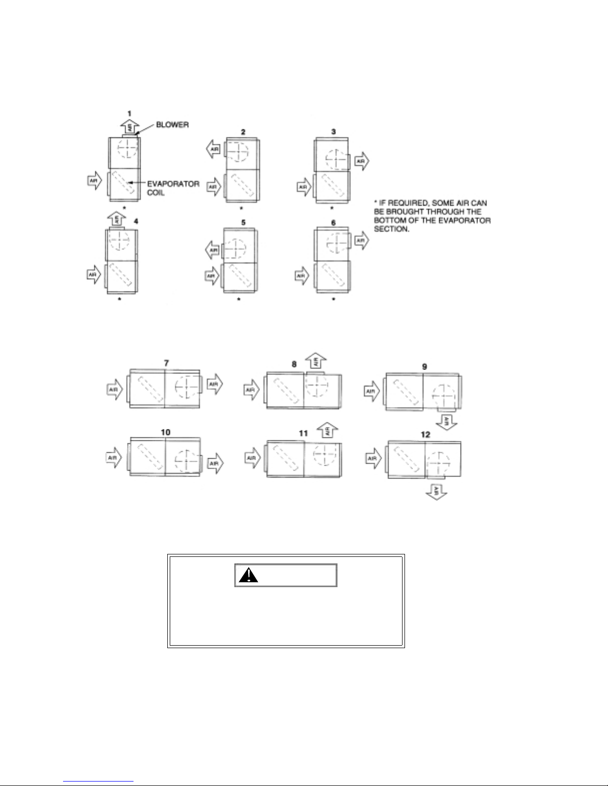
APPLICATION FLEXIBILITY INDOOR
BLOWER M OTOR
LO C A TIO N
AIR OUT
(S td. Arrangem ent)
BLOW ER
SECTIO N
RETURN AIR
DUCT FLANGE
AIR
IN
FILTERS
VERTIC AL
POSITIO N
NOTE:
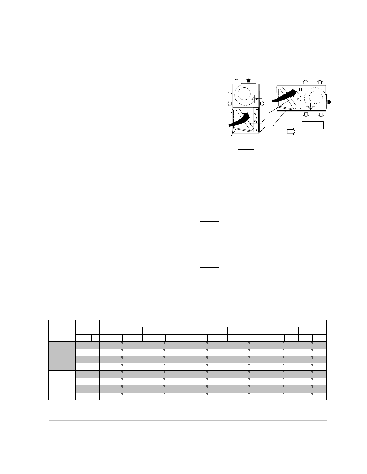
FIGURE 1 : TYPICAL INDOOR UNIT
APPLICATIONS
The indoor units are built in a single cabinet with one condensate drain pan. These units can be installed in either the vertical or horizontal position for maximum flexibility.
NOTE:
indoor coil keeps the condensate from dripping off the finned
surface onto the filters:
NOTE:
with the condensate drain pan under the entire indoor coil.
On vertical applications, the air velocity across the
On horizontal applications the unit must be installed
RETURN AIR
DUCT FLANGE
BLOW ER
SECTIO N
EVAPOR ATOR
COIL
COIL
SECTIO N
DISCHARGE ARRANGEMENTS
C E R T A IN B L O W E R P O S IT IO N S A R E N O T R E C O M M E N D E D .
BECAUSE TH E BLOW ER M O TOR SH OU LD NO T BE M OU NTED
UPSIDE DO W N.
FILTERS
ALTER NATE AIR
HORIZONTAL
POSITIO N
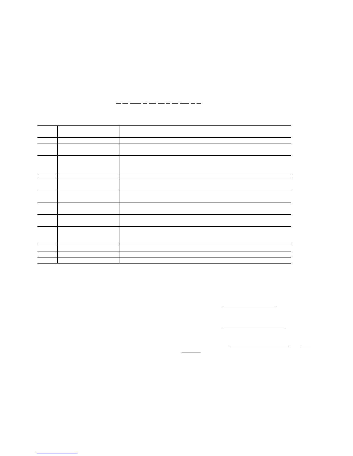
CONDENSER ONLY CAPACITY
Suction
Model HL
240
180
ress. &
65 75 85 95 105 115
PSIG ºF MBH KW* MBH KW* MBH KW* MBH KW* MBH KW* MBH KW*
61.5 35 255 17.2 243 18.6 231 20.1 219 21.9 207 23.9 195 26.2
68.5 40 275 17.6 263 19.0 250 20.6 238 22.4 225 24.4 212 26.7
76 45 296 18.1 283 19.5 270 21.1 257 22.9 243 24.9 230 27.2
84 50 319 18.7 305 20.0 291 21.6 277 23.4 263 25.5 248 27.7
61.5 35 191 12.7 182 13.7 172 14.9 163 16.2 153 17.7 143 19.4
68.5 40 207 13.0 197 14.0 187 15.2 177 16.5 167 18.0 157 19.8
76 45 224 13.3 214 14.4 203 15.5 193 16.9 182 18.4 171 20.2
84 50 241 13.7 230 14.7 219 15.9 208 17.3 197 18.8 186 20.6
*Power consumption includes outdoor fans and compressors only.
NOTE:
The Supply Air Plenum and the Return Air Grille
accessories can be used on either arrangement.
NOTE: TheBaseaccessorycanonlybeusedonthevertical
arrangement.
Tem perature of Air on Condenser Coil, ºF
Unitary Products Group 3
Page 4
036-21326-001-C-0202
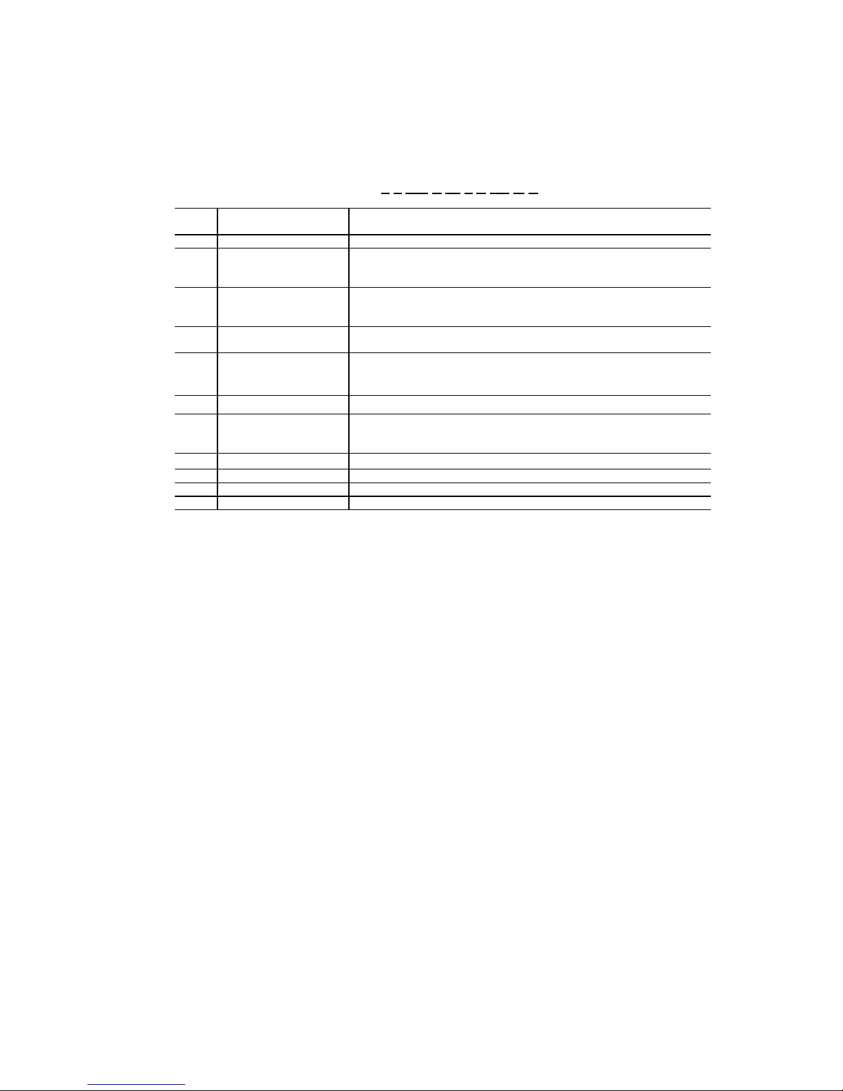
OUTDOOR CONDENSING UNITS AND HEAT PUMPS
PRODUCT NOMENCLATURE
(UPG BRANDS)
H F - 10 C 00 A T A AA 1 A
Model # Model Number
Description
H Product Category
F Product Identifier
-10 Nominal Cooling
Capacity
MBH
C Heat Type
00 Nominal Heating
Capacity
A Airflow Options
T Voltage
A Installation Options
AA Special Options
1 Generation
A Style
Options
H = Air Conditioner Split System E = Split System Heat Pump
F = R-22 Standard Efficiency 2-Pipe
L = R-22 Standard Efficiency 4-Pipe
-07 = 7-1/2 Ton
-10 = 10 Ton
C = Cooling Only
00 = No Heat Installed
A = Standard Motor
T= 208/230-3-60
W= 460-3-60
A = None
B = Disconnect
AA = None
AC = Technicoat
1 = First Generation 2 = Second Generation
A = Style A B = Style B
FIGURE 2 : OUTDOOR PRODUCT NOMENCLATURE
OUTDOOR UNIT
Every unit includes 2 heavy-duty scroll compressors, 2 outdoor fan motors with inherent protection, subfusing and a
copper tube/aluminum fin coil.
All controls are located in the front of the unit in the control
box and are readily accessible for maintenance, adjustment
and service. All wiring (power and control) can be made
through the front of the unit.
-15 = 15 Ton
-20 = 20 Ton
X= 575-3-60
ACCESSORIES (FACTORY & FIELD
INSTALLED)
• Factory installed Non-Fused Disconnect for safety and
convenience.
• Factory installed Technicoat Condenser Coil
sion protection.
• Field Installed VFD (Variable Frequency Drive
Ambient operation down to 0ºF.
s for corro-
) for Low
4 Unitary Products Group
• Field Installed Hot Gas Bypass for low load operation.
• Field installed Pump-Out Kit for applications where liquid
slugging could be an issue.
Page 5
INDOOR SPLIT UPG PRODUCT NOMENCLATURE
L F –10 C 00 T A AA 1 A
036-21326-001-C-0202
Model # Model Number
Description
L Product Category
F
Product Identifier
-10 Nominal Cooling
Capacity
MBH
C Heat Type
00 Nominal Heating
Capacity
A Airflow Options
F Voltage
A Factory Options
AA Special Options
1 Generation
A Product Style
* NOT AVAILABLE IN HEAT PUMP.
Options
L = Air Handling Unit- Cooling F = Air Handling Unit- Heat Pump
F = R-22 Standard Efficiency 2-Pipe
L = R-22 Standard Efficiency 4-Pipe
-07 = 7-1/2 Ton
-10 =10 Ton
C = Cooling Only
00= No Heat Installed
A = None
F = 208/230-1-60
T = 208/230-3-60
W=460-3-60
A = None
AA = None
1 = First Generation 2 = Second Generation
A = Style A B = Style B
FIGURE 3 : INDOOR PRODUCT NOMENCLATURE
INDOOR UNIT
Every unit includes a well-insulated cabinet, copper tube/aluminum fin coil with interlaced circuiting arrangement, 2"
throwaway filters, adjustable TXV’s and centrifugal blowers.
Blower motors and drive kits are ordered separately.
The controls include 208/230/460 volt transformer, blower
motor contactor and relay, and a low voltage terminal block.
The units are shipped in the vertical position ready for field
installation. For horizontalinstallation, the blower module can
be repositioned in the field as shown on pages 3 and 6 for
maximum flexibility.
-15 = 15 Ton
-20 = 20 Ton
S = 208/230-460-3-60
• Base Sections are available to raise vertical indoor units
above the floor. Outdoor air may be introduced through
these bases by cutting an access opening for the outdoor air duct connection. These bases are finished to
match the exterior of the basic unit. They may have to be
insulated in the field for certain applications.
• Suspension Kit is available for indoor units installed horizontally.
• Manual and electronic two stage thermostats are available for cooling applications.
• Both thermostats have a two-position fan switch, AUTO
and ON to provide intermittent or continuous blower
operation.
ACCESSORIES INDOOR UNIT
(FIELD INSTALLED)
• Supply Air Plenums and Return Air Grilles (expanded
metal) accessories are available for free-standing indoor
(15 Ton units only) units located in the conditioned
space. Both accessories are finished to match the exterior of the basic unit, and both can be applied with either
vertical or horizontal units. The supply air plenums are
fully insulated and have double-deflection, adjustable
grilles.
Unitary Products Group 5
Page 6
036-21326-001-C-0202
FIGURE 4 : VERTICAL ARRANGEMENTS - LL180 AND LL240
FIGURE 5 : HORIZONTAL ARRANGEMENTS - LL180 AND LL240
CERTAINBLOWERPOSITIONSARENOT
RECOMMENDED BECAUSE THE BLOWER
MOTOR SHOULD NOT BE MOUNTED UPSIDE
DOWN.
6 Unitary Products Group
.
CAUTION
Page 7
036-21326-001-C-0202
TABLE 1: UNIT APPLICATION DATA
Application Limitations Minimum Maximum
Voltage Variation (208/230-3-60) - Volts 187 253
Voltage Variation (460-3-60) - Volts 414 506
AmbientAir on OutdoorCoil (CoolingCycle) - °F 45 115
AmbientAir on IndoorCoil (Cooling Cycle) - °F 68 86
TABLE 2: ARI RATINGS - COOLING AND SOUND
Model
Outdoor
Unit
HL180 LL180 180 9.7 10.4 89.0 6000 0.35
HL240 LL240 240 9.7 10.4 90.0 8000 0.40
1. Ratings are in accordancew ith ARI standard 340/360.
2. Ratings are in accordance with ARI standard 370.
IndoorUnit
MBH EER IPLV dB CFM IWG
CoolingCapacity
1
Cond. Unit
2
Sound
Rated Airflow Rated ESP
TABLE 3: ELECTRICAL DATA COMPRESSORS
Compressors
Model
Number
HL180 208/230-3-60 25.6 190.0 25.6 190.0
HL180 460-3-60 12.8 95.0 12.8 95.0
HL240 208/230-3-60 42.0 239.0 42.0 239.0
HL240 460-3-60 19.2 125.0 19.2 125.0
Power
Supply
System 1 System 2
RLA LRA RLA LRA
TABLE 4: ELECTRICAL DATA FAN MOTORS
Model
Number
HL180 208/230-3-60 2 3.7
HL180 460-3-60 2 1.85
HL240 208/230-3-60 2 5.8
HL240 460-3-60 2 2.9
TABLE 5: ELECTRICAL DATA, OUTDOOR MCA & MAX. FUSE SIZE
Model
Number
HL180 208/230-3-60 65.1 90
HL180 460-3-60 32.5 45
HL240 208/230-3-60 106.1 125
HL240 460-3-60 49.0 60
1. Maximum fuse or maximum circuit breaker (HACR type per NEC).
Unitary Products Group 7
Power
Supply
Power
Supply
Condenser Fans
Min. Circuit
Ampacity
Qty. FLA
Max.
Fuse
Size
ea.
1
Page 8
036-21326-001-C-0202
TABLE 6: OUTDOOR UNIT PHYSICAL DATA
Description
Unit Model
HL180 HL240
Compressor
1
Fans
Fan Motors
2
Coil
Refrigerant - 22 (lbs -oz.)
Unit Weight (lbs)
1. These compressors are fully hermetic.
2. The ball bearing, 56 frame, single phase condenser fan motors have internal protection and are directly connected to the condenser fans. Motor
rotation is counterclockwise when viewing the lead end, which is opposite the shaft end.
3. The amount of charge in the unit as shipped from the factory.
4. Total operating charge for the condensing unit, matching indoor unit, and 25 feet of interconnecting pipe.
Rating - (Qty) Tons 2 X 7.5 = 15 Tons 2 X 10 = 20 Tons
Quantity 2 2
Diameter - inches 24 30
Blades/Pitch (°) 3/34 3/22
Nominal CFM 11,600 15,200
HP 1 1.5
RPM 1140 1100
Rows Deep X Rows High 2 X 30 2 X 30
Finned Length - inches each slab 60 78
Face Area - square feet (both slabs) 25 32.5
Tube(Copper) OD - inches 3/8 3/8
Fins(Aluminum) per inch 16 16
Holding Charge (sys1/sys2)
Operating Charge (sys1/sys2)
Shipping 944 1380
Operating 957 1396
3
4
1-0/1-0lbs. 1-0/1-0lbs.
14.0/14.0 lbs. 17.0/17.0 lbs.
TABLE 7: INDOOR UNIT PHYSICAL DATA
Description
Rows Deep X Rows High 3 X 32 3 X 40
Finned length- Inches 83 81
Coil
Centrifugal Blower
(Forward Curve - Qty
Blower Motor
1
Filters
(Throwaway)
Unit Weight (lbs)
Accessory Operating
Weight (lbs)
1. Refer to Table 20 and 22 for more inform ation.
Face Area - Square Feet 18.4 22.5
Tube (Copper) OD - Inches 3/8 3/8
Fins (Aluminum) per Inch 13 16
DiameterXWidth-Inches 15X12-2 18X18-2
HP Field Installed
RPM -- -Quantity Per Unit 4/4 10
Size-Inches 20X21X2&22X24X2 20X25X2
Total Face Area - Square Feet 25.8 34.7
Shipping 720 990
Operating 830 1115
Motor & Drive
Supply Air Plenum 185 N/A
Return Air Grille 25 N/A
Base 140 210
Unit Model
LL180 LL240
3HP 47 -5HP 120 120
8 Unitary Products Group
Page 9

036-21326-001-C-0202
All dimensions are in inches. They are
subject to change without notice. Certified dimensions will be provided upon
C
request.
OUTDOOR UNIT DIMENSIONS
A
Unit
Dimensions (In.)
ABC
B
TABLE 8: CONNECTIONS
Connection Entry Connection Size
15 Ton 20 Ton
Suction Line 1-1/8 ID 1-3/8 ID
Liquid Line 5/8 ID 5/8 ID
Power Wiring 2-1/8 KO 2-1/8 KO
Control Wiring 7/8 KO 7/8 KO
TABLE 9: UNIT CLEARANCES
Location Dimensions
Overhead (Top)
Front access panels 36”
Left Side 30”
Right Side 30”
Rear 24”
Bottom
1
2
120”
0”
15 Ton 37.5 45.75 110.5
20 Ton 37.5 45.75 128.1
Dimensions (in.)
Unit
ABC
15 Ton 23 47 110
20 Ton 23 52 128
TABLE 10: HL CENTER OF GRAVITY DIMENSIONS
APPROXIMATE
CENTER OF GRAVITY
X END
B
C
CONTRO
L BO
46
A
FIGURE 6 : CENTER OF GRAVITY
1. Units must be installed outdoors. Overhanging structures or
shrubs should not obstruct condenser air discharge.
2. Adequate snow clearance must be provided if winter operation
is expected.
UNIT SIZE
15 Ton Outdoor 944 959 205 275 275 205 110 46 47 23
20 ton Outdoor 1124 1141 232 339 339 232 128 46 52 23
SHIPPING
WEIGHT
FIGURE 7 : HL CORNER WEIGHT
Unitary Products Group 9
OPERATING
WEIGHT
LEFT
ABCD
D
CG
A
dim X
LENGTH
FRONT
UNIT
LENGTH
C
WIDTH
dim Y
B
UNIT
WIDTH
DIM X DIM Y
Page 10

036-21326-001-C-0202
FIGURE 8 : PIPING AND ELECTRICAL CONNECTION LOCATIONS
TABLE 11: PIPING AND ELECTRICAL CONNECTION SIZES
CONNECTION ENT RY
A
B
C
D
E
F
10 Unitary Products Group
SIZE
SUCTION LINE SYS #1 1-3/8 ID
LIQUID LINE SYS. #1 5/8 OD
SUCTION LINE SYS. #2 1-3/8 ID
LIQUID LINE SYS. #2 5/8 OD
POWER WIRING 2” KO
CONTROL WIRING 7/8 KO
Page 11

036-21326-001-C-0202
TABLE 12: 15 TON CAPACITY TABLE - 85º AND 95ºF
15 Ton Capacity Tables
HL180 Matched with LL180
AIR ON EVAPORATOR
CFM W.B. GROSS INPUT GROSS SENSIBLE CAPACITY (MBh)
TEMP CAP. POWER (RETURN AIR DRY BULB TEMP.- (F))
(F) (MBh) (kW) 86 83 80 77 74 71 68
4500 72 197.8 15.23 117.3 104.5 91.6 78.8 66.0 #N/A #N/A
67 183.8 14.90 144.8 131.9 119.1 106.3 93.4 80.6 67.8
62 170.5 14.50 168.2 155.4 142.6 129.8 116.9 104.1 91.3
57 173.8 14.43 173.8 171.0 158.2 145.3 132.5 119.7 106.9
5250 72 204.1 15.34 129.7 114.5 99.4 84.2 69.0 #N/A #N/A
67 189.6 15.01 159.4 144.3 129.1 114.0 98.8 83.6 68.5
62 175.9 14.60 174.8 168.3 154.6 139.4 124.3 109.1 93.9
57 179.3 14.53 179.3 177.9 171.5 156.3 141.2 126.0 110.8
6000 72 210.3 15.44 142.1 124.6 107.1 89.6 72.1 #N/A #N/A
67 195.4 15.12 174.1 156.6 139.1 121.6 104.1 86.6 69.2
62 181.3 14.70 181.3 181.3 166.6 149.1 131.6 114.1 96.6
57 184.8 14.64 184.8 184.8 184.8 167.3 149.8 132.3 114.8
6750 72 213.6 15.54 152.3 132.4 112.5 92.6 72.6 #N/A #N/A
67 198.4 15.21 186.0 166.1 146.2 126.3 106.3 86.4 66.5
62 184.0 14.80 184.0 184.0 175.0 155.1 135.2 115.3 95.3
57 187.6 14.73 187.6 187.6 187.6 167.7 147.8 127.8 107.9
7500 72 216.8 15.64 162.6 140.3 117.9 95.6 73.2 #N/A #N/A
67 201.4 15.31 198.0 175.6 153.3 130.9 108.5 86.2 63.8
62 186.8 14.89 186.8 186.8 183.5 161.1 138.8 116.4 94.1
57 190.5 14.82 190.5 190.5 190.5 168.1 145.7 123.4 101.0
Indicates Nominal Capacity Rating Point.
INPUT POWER INCLUDES THE CONDENSER AND COMPRESSOR MOTORS BUT NOT THE INDOOR BLOWER MOTOR
OUTDOOR AMBIENT TEMPERATURE (F):
85º
15 Ton Capacity Tables
HL180 Matched with LL180
AIRONEVAPORATOR
CFM W.B. GROSS INPUT GROSS SENSIBLE CAPACITY (MBh)
TEMP CAP. POWER (RETURN AIR DRY BULB TEMP.-(F)
(F) (MBh) (kW) 86 83 80 77 74 71 68
4500 72 190.9 16.89 114.1 101.3 88.5 75.7 62.8 #N/A #N/A
67 176.8 16.51 142.2 129.4 116.5 103.7 90.9 78.0 65.2
62 162.8 16.18 162.8 153.2 140.3 127.5 114.7 101.8 89.0
57 163.2 16.11 163.2 158.1 145.2 132.4 119.6 106.7 93.9
5250 72 196.2 16.99 126.2 111.0 95.8 80.7 65.5 #N/A #N/A
67 181.7 16.61 156.5 141.4 126.2 111.0 95.9 80.7 65.6
62 167.4 16.27 167.4 162.5 152.0 136.8 121.6 106.5 91.3
57 167.7 16.20 167.7 165.2 157.3 142.1 127.0 111.8 96.6
6000 72 201.5 17.09 138.2 120.7 103.2 85.7 68.2 #N/A #N/A
67 186.6 16.71 170.9 153.4 135.9 118.4 100.9 83.4 65.9
62 171.9 16.37 171.9 171.9 163.6 146.1 128.6 111.1 93.6
57 172.3 16.30 172.3 172.3 169.3 151.8 134.4 116.9 99.4
6750 72 205.1 17.17 148.4 128.5 108.6 88.6 68.7 #N/A #N/A
67 190.0 16.79 182.1 162.9 143.0 123.1 103.1 83.2 63.3
62 175.0 16.45 175.0 175.0 170.9 150.9 131.0 111.1 91.2
57 175.4 16.37 175.4 175.4 173.9 154.0 134.1 114.2 94.2
7500 72 208.8 17.25 158.7 136.3 114.0 91.6 69.2 #N/A #N/A
67 193.4 16.86 193.4 172.4 150.1 127.7 105.4 83.0 60.7
62 178.1 16.52 178.1 178.1 178.1 155.7 133.4 111.0 88.7
57 178.5 16.45 178.5 178.5 178.5 156.2 133.8 111.4 89.1
Indicates Nominal Capacity Rating Point.
INPUT POWER INCLUDES THE CONDENSER AND COMPRESSOR MOTORS BUT NOT THE INDOOR BLOWER MOTOR
OUTDOOR AMBIENT TEMPERATURE(F):
95º
Unitary Products Group 11
Page 12

036-21326-001-C-0202
TABLE 13: 15 TON CAPACITY TABLE - 105º AND 115ºF
15 Ton Capacity Tables
HL180 Matched with LL180
AIRONEVAPORATOR
CFM W.B. GROSS INPUT GROSS SENSIBLE CAPACITY (MBh)
TEMP CAP. POWER (RETURN AIR DRY BULB TEMP.-(F)
(F) (MBh) (kW) 86 83 80 77 74 71 68
4500 72
67
62
57
5250 72
67
62
57
6000 72
67
62
57
6750 72
67
62
57
7500 72
67
62
57
Indicates Nominal Capacity Rating Point.
INPUT POWER INCLUDES THE CONDENSER AND COMPRESSOR MOTORS BUT NOT THE INDOOR BLOWER MOTOR
182.8 18.89 111.9 99.1 86.2 73.4 60.6 #N/A #N/A
168.9 18.42 139.2 126.3 113.5 100.7 87.8 75.0 62.2
156.1 18.00 156.1 150.4 137.6 124.7 111.9 99.1 86.2
157.8 17.99 157.8 152.5 139.7 126.8 114.0 101.2 88.3
187.6 19.03 123.6 108.5 93.3 78.1 63.0 #N/A #N/A
173.4 18.56 153.1 137.9 122.8 107.6 92.4 77.3 62.1
160.2 18.13 160.2 157.4 148.8 133.6 118.5 103.3 88.1
162.0 18.13 162.0 159.3 151.1 135.9 120.7 105.6 90.4
192.4 19.17 135.3 117.8 100.3 82.8 65.3 #N/A #N/A
177.8 18.70 167.0 149.5 132.0 114.6 97.1 79.6 62.1
164.3 18.27 164.3 164.3 160.0 142.5 125.0 107.5 90.1
166.1 18.26 166.1 166.1 162.5 145.0 127.5 110.0 92.5
196.1 19.23 146.1 126.2 106.2 86.3 66.4 #N/A #N/A
181.2 18.76 175.9 159.8 139.8 119.9 100.0 80.1 60.1
167.5 18.33 167.5 167.5 165.4 145.4 125.5 105.6 85.7
169.3 18.32 169.3 169.3 167.5 147.6 127.7 107.7 87.8
199.8 19.30 156.9 134.5 112.2 89.8 67.4 #N/A #N/A
184.7 18.82 184.7 170.0 147.6 125.3 102.9 80.5 58.2
170.7 18.39 170.7 170.7 170.7 148.3 126.0 103.6 81.3
172.5 18.38 172.5 172.5 172.5 150.2 127.8 105.5 83.1
OUTDOOR AMBIENT TEMPERATURE (F):
105º
15 Ton Capacity Tables
HL180 Matched with LL180
AIR ON EVAPORATOR
CFM W.B. GROSS INPUT GROSS SENSIBLE CAPACITY (MBh)
TEMP CAP. POWER (RETURN AIR DRY BULB TEMP.-(F)
(F) (MBh) (kW) 86 83 80 77 74 71 68
4500 72 174.7 20.88 109.7 96.8 84.0 71.2 58.3 #N/A #N/A
67 161.0 20.33 136.1 123.3 110.5 97.6 84.8 72.0 59.1
62 149.4 19.81 149.4 147.6 134.8 122.0 109.1 96.3 83.5
57 152.5 19.88 152.5 146.9 134.1 121.2 108.4 95.6 82.8
5250 72 179.0 21.06 121.1 105.9 90.8 75.6 60.4 #N/A #N/A
67 165.0 20.51 149.7 134.5 119.3 104.2 89.0 73.9 58.7
62 153.1 19.99 153.1 152.2 145.6 130.5 115.3 100.1 85.0
57 156.2 20.05 156.2 153.4 144.8 129.7 114.5 99.4 84.2
6000 72 183.3 21.25 132.5 115.0 97.5 80.0 62.5 #N/A #N/A
67 168.9 20.69 163.2 145.7 128.2 110.7 93.2 75.7 58.2
62 156.8 20.16 156.8 156.8 156.5 139.0 121.5 104.0 86.5
57 159.9 20.23 159.9 159.9 155.6 138.1 120.6 103.1 85.6
6750 72 187.1 21.30 143.8 123.9 103.9 84.0 64.1 #N/A #N/A
67 172.4 20.73 169.6 156.6 136.7 116.8 96.8 76.9 57.0
62 160.0 20.21 160.0 160.0 159.9 139.9 120.0 100.1 80.2
57 163.2 20.27 163.2 163.2 161.1 141.2 121.2 101.3 81.4
7500 72 190.9 21.34 155.1 132.7 110.4 88.0 65.7 #N/A #N/A
67 175.9 20.78 175.9 167.5 145.1 122.8 100.4 78.1 55.7
62 163.3 20.25 163.3 163.3 163.3 140.9 118.5 96.2 73.8
57 166.6 20.32 166.6 166.6 166.6 144.2 121.8 99.5 77.1
Indicates Nominal Capacity Rating Point.
INPUT POWER INCLUDES THE CONDENSER AND COMPRESSOR MOTORS BUT NOT THE INDOOR BLOWER MOTOR
OUTDOOR AMBIENT TEMPERATURE (F):
115º
12 Unitary Products Group
Page 13

TABLE 14: 15 TON CAPACITY TABLE - 125ºF
15 Ton Capacity Tables
HL180 Matched with LL180
AIR ON EVAPORATOR
CFM W.B. GROSS INPUT GROSS SENSIBLE CAPACITY (MBh)
TEMP CAP. POWER (RETURN AIR DRY BULB TEMP.-(F)
(F) (MBh) (kW) 86 83 80 77 74 71 68
4500 72
67
62
57
5250 72
67
62
57
6000 72
67
62
57
6750 72
67
62
57
7500 72
67
62
57
Indicates Nominal Capacity Rating Point.
INPUT POWER INCLUDES THE CONDENSER AND COMPRESSOR MOTORS BUT NOT THE INDOOR BLOWER MOTOR
166.6 22.9 107.4 94.6 81.8 68.9 56.1 #N/A #N/A
153.1 22.2 133.1 120.3 107.4 94.6 81.8 68.9 56.1
142.7 21.6 142.7 142.7 132.0 119.2 106.4 93.5 80.7
147.1 21.8 147.1 141.3 128.5 115.7 102.8 90.0 77.2
170.4 23.1 118.5 103.4 88.2 73.1 57.9 #N/A #N/A
156.6 22.5 146.2 131.1 115.9 100.8 85.6 70.4 55.3
146.0 21.8 146.0 146.0 142.5 127.3 112.1 97.0 81.8
150.4 22.0 150.4 147.6 138.6 123.5 108.3 93.1 78.0
174.2 23.3 129.7 112.2 94.7 77.2 59.7 #N/A #N/A
160.1 22.7 159.4 141.9 124.4 106.9 89.4 71.9 54.4
149.2 22.1 149.2 149.2 149.2 135.4 117.9 100.4 82.9
153.8 22.2 153.8 153.8 148.8 131.3 113.8 96.3 78.8
178.0 23.4 141.5 121.5 101.6 81.7 61.8 #N/A #N/A
163.6 22.7 163.3 153.5 133.5 113.6 93.7 73.8 53.8
152.5 22.1 152.5 152.5 152.5 134.4 114.5 94.6 74.7
157.2 22.2 157.2 157.2 154.7 134.7 114.8 94.9 75.0
181.9 23.4 153.3 130.9 108.6 86.2 63.9 #N/A #N/A
167.2 22.7 167.2 165.0 142.7 120.3 98.0 75.6 53.2
155.8 22.1 155.8 155.8 155.8 133.5 111.1 88.8 66.4
160.6 22.3 160.6 160.6 160.6 138.2 115.9 93.5 71.2
OUTDOOR AMBIENT TEMPERATURE (F):
036-21326-001-C-0202
125º
Unitary Products Group 13
Page 14

036-21326-001-C-0202
TABLE 15: 20 TON CAPACITY TABLE - 85º AND 95ºF
20 Ton Capacity Tables
HL240 & LL240
AIRONEVAPORATOR
CFM W.B. GROSS INPUT GROSS SENSIBLE CAPACITY (MBh)
TEMP CAP. POWER (RETURN AIR DRY BULB TEMP.-(F)
(F) (MBh) (kW) 86 83 80 77 74 71 68
6000 72
67
62
57
7000 72
67
62
57
8000 72
67
62
57
8600 72
67
62
57
9200 72
67
62
57
263.4 21.25 155.9 138.8 121.7 104.6 87.5 #N/A #N/A
243.5 20.69 191.0 173.9 156.8 139.7 122.6 105.5 88.4
227.6 20.42 221.1 204.0 186.9 169.8 152.7 135.6 118.5
219.5 20.19 219.5 216.7 199.6 182.5 165.4 148.3 131.2
273.9 21.38 172.8 152.6 132.4 112.2 91.9 #N/A #N/A
253.2 20.82 211.0 190.8 170.6 150.3 130.1 109.9 89.7
236.7 20.54 233.4 223.5 203.3 183.1 162.9 142.6 122.4
228.2 20.31 228.2 226.8 217.1 196.9 176.7 156.4 136.2
284.4 21.51 189.7 166.4 143.0 119.7 96.4 #N/A #N/A
262.9 20.94 231.0 207.6 184.3 161.0 137.6 114.3 91.0
245.7 20.67 245.7 243.0 219.7 196.3 173.0 149.7 126.4
237.0 20.43 237.0 237.0 234.6 211.3 187.9 164.6 141.3
289.0 21.64 197.6 172.2 146.8 121.5 96.1 #N/A #N/A
267.2 21.06 239.9 214.6 189.2 163.8 138.4 113.0 87.7
249.7 20.79 249.7 248.3 225.5 200.1 174.7 149.4 124.0
240.8 20.55 240.8 240.8 239.6 214.2 188.9 163.5 138.1
293.6 21.76 205.5 178.0 150.6 123.2 95.8 #N/A #N/A
271.4 21.19 248.9 221.5 194.1 166.6 139.2 111.8 84.4
253.7 20.91 253.7 253.7 231.3 203.9 176.5 149.0 121.6
244.6 20.67 244.6 244.6 244.6 217.2 189.8 162.4 134.9
Indicates Nominal Capacity Rating Point.
INPUT POWER INCLUDES THE CONDENSER AND COMPRESSOR MOTORS BUT NOT THE INDOOR BLOWER MOTOR
OUTDOOR AMBIENT TEMPERATURE (F):
85º
AIRONEVAPORATOR
CFM W.B. GROSS INPUT GROSS SENSIBLE CAPACITY (MBh)
TEMP CAP. POWER (RETURN AIR DRY BULB TEMP.-(F)
(F) (MBh) (kW) 86 83 80 77 74 71 68
6000 72
67
62
57
7000 72
67
62
57
8000 72
67
62
57
8600 72
67
62
57
9200 72
67
62
57
253.7 23.11 151.3 134.2 117.0 99.9 82.8 #N/A #N/A
237.2 22.68 188.2 171.1 153.9 136.8 119.7 102.6 85.5
218.5 22.16 218.5 202.7 185.6 168.5 151.4 134.3 117.2
214.5 22.11 214.5 210.5 193.4 176.3 159.1 142.0 124.9
262.8 23.30 167.5 147.3 127.1 106.8 86.6 #N/A #N/A
245.7 22.88 207.5 187.3 167.1 146.9 126.7 106.5 86.2
226.4 22.35 226.4 218.5 201.5 181.3 161.0 140.8 120.6
222.2 22.30 222.2 220.2 209.9 189.7 169.5 149.2 129.0
271.9 23.50 183.7 160.4 137.1 113.7 90.4 #N/A #N/A
254.3 23.07 226.9 203.6 180.3 156.9 133.6 110.3 87.0
234.2 22.54 234.2 234.2 217.3 194.0 170.7 147.4 124.0
229.9 22.49 229.9 229.9 226.4 203.1 179.8 156.4 133.1
269.7 23.60 189.5 164.1 138.7 113.3 88.0 #N/A #N/A
252.2 23.16 233.2 207.8 182.4 157.1 131.7 106.3 80.9
232.3 22.63 232.3 232.3 220.0 194.6 169.2 143.8 118.5
228.0 22.58 228.0 228.0 226.3 200.9 175.5 150.2 124.8
267.6 23.69 195.2 167.8 140.4 112.9 85.5 #N/A #N/A
250.2 23.26 239.5 212.0 184.6 157.2 129.8 102.3 74.9
230.4 22.72 230.4 230.4 222.6 195.2 167.7 140.3 112.9
226.2 22.68 226.2 226.2 226.2 198.7 171.3 143.9 116.5
Indicates Nominal Capacity Rating Point.
INPUT POWER INCLUDES THE CONDENSER AND COMPRESSOR MOTORS BUT NOT THE INDOOR BLOWER MOTOR
14 Unitary Products Group
20 Ton Capacity Tables
HL240 & LL240
OUTDOOR AMBIENT TEMPERATURE (F):
95º
Page 15

TABLE 16: 20 TON CAPACITY TABLE - 105º & 115ºF
20 Ton Capacity Tables
AIRONEVAPORATOR
CFM W.B. GROSS INPUT GROSS SENSIBLE CAPACITY (MBh)
6000
TEMP CAP. POWER (RETURN AIR DRY BULB TEMP.-(F)
(F) (MBh) (kW) 86 83 80 77 74 71 68
72 245.6 25.60 148.7 131.6 114.5 97.4 80.2 #N/A #N/A
67 228.4 25.00 184.5 167.4 150.3 133.2 116.1 99.0 81.9
62 211.9 24.47 211.9 198.0 180.9 163.7 146.6 129.5 112.4
57 210.8 24.50 210.8 204.7 187.6 170.5 153.4 136.3 119.2
7000
72 253.0 25.77 164.4 144.2 124.0 103.7 83.5 #N/A #N/A
67 235.2 25.16 203.2 183.0 162.8 142.5 122.3 102.1 81.9
62 218.3 24.63 218.3 211.3 195.9 175.7 155.4 135.2 115.0
57 217.1 24.66 217.1 214.1 203.2 183.0 162.8 142.5 122.3
8000
72 260.4 25.94 180.1 156.8 133.5 110.1 86.8 #N/A #N/A
67 242.1 25.32 221.9 198.6 175.2 151.9 128.6 105.3 81.9
62 224.7 24.79 224.7 224.7 210.9 187.6 164.2 140.9 117.6
57 223.4 24.82 223.4 223.4 218.8 195.4 172.1 148.8 125.5
8600
72 261.9 26.04 188.1 162.7 137.3 112.0 86.6 #N/A #N/A
67 243.5 25.43 230.7 205.7 180.3 154.9 129.6 104.2 78.8
62 226.0 24.89 226.0 226.0 217.0 191.6 166.2 140.9 115.5
57 224.8 24.92 224.8 224.8 222.4 197.1 171.7 146.3 120.9
9200
72 263.4 26.15 196.1 168.6 141.2 113.8 86.4 #N/A #N/A
67 244.9 25.53 239.5 212.8 185.4 158.0 130.5 103.1 75.7
62 227.3 24.99 227.3 227.3 223.1 195.7 168.2 140.8 113.4
57 226.1 25.03 226.1 226.1 226.1 198.7 171.2 143.8 116.4
Indicates Nominal Capacity Rating Point.
INPUT POWER INCLUDES THE CONDENSER AND COMPRESSOR MOTORS BUT NOT THE INDOOR BLOWER MOTOR
HL240 & LL240
OUTDOOR AMBIENT TEMPERATURE (F):
036-21326-001-C-0202
105º
20 Ton Capacity Tables
AIRONEVAPORATOR
CFM W.B. GROSS INPUT GROSS SENSIBLE CAPACITY (MBh)
TEMP CAP. POWER (RETURN AIR DRY BULB TEMP.-(F)
6000 72
7000 72
8000 72
8600 72
9200 72
(F) (MBh) (kW) 86 83 80 77 74 71 68
237.4 28.09 146.1 129.0 111.9 94.8 77.7 #N/A #N/A
67
62
57
219.5 27.31 180.8 163.7 146.6 129.5 112.4 95.3 78.2
205.4 26.78 205.4 193.2 176.1 159.0 141.9 124.8 107.7
207.1 26.89 207.1 199.0 181.9 164.8 147.7 130.6 113.4
243.1 28.23 161.3 141.1 120.9 100.7 80.4 #N/A #N/A
67
62
57
224.8 27.45 198.9 178.6 158.4 138.2 118.0 97.8 77.5
210.3 26.91 210.3 204.2 190.3 170.0 149.8 129.6 109.4
212.0 27.02 212.0 208.0 196.5 176.3 156.1 135.8 115.6
248.8 28.37 176.5 153.2 129.9 106.5 83.2 #N/A #N/A
67
62
57
230.0 27.58 216.9 193.5 170.2 146.9 123.6 100.2 76.9
215.2 27.04 215.2 215.2 204.4 181.1 157.8 134.4 111.1
217.0 27.15 217.0 217.0 211.1 187.8 164.5 141.1 117.8
254.0 28.49 186.7 161.3 136.0 110.6 85.2 #N/A #N/A
67
62
57
234.8 27.70 228.2 203.6 178.2 152.8 127.4 102.1 76.7
219.7 27.15 219.7 219.7 214.0 188.6 163.3 137.9 112.5
221.5 27.26 221.5 221.5 218.6 193.2 167.8 142.4 117.1
259.2 28.61 196.9 169.5 142.0 114.6 87.2 #N/A #N/A
67
62
57
239.6 27.81 239.6 213.6 186.2 158.7 131.3 103.9 76.5
224.1 27.26 224.1 224.1 223.6 196.2 168.7 141.3 113.9
226.0 27.38 226.0 226.0 226.0 198.6 171.2 143.8 116.3
HL240 & LL240
OUTDOOR AMBIENT TEMPERATURE (F):
Indicates Nominal Capacity Rating Point.
INPUT POWER INCLUDES THE CONDENSER AND COMPRESSOR MOTORS BUT NOT THE INDOOR BLOWER MOTOR
115º
Unitary Products Group 15
Page 16

036-21326-001-C-0202
TABLE 17: 20 TON CAPACITY TABLE - 125ºF
20 Ton Capacity Tables
HL240 & LL240
AIRONEVAPORATOR
CFM W.B. GROSS INPUT GROSS SENSIBLE CAPACITY (MBh)
TEMP CAP. POWER (RETURN AIR DRY BULB TEMP.-(F)
6000 72
7000 72
8000 72
8600 72
9200 72
(F) (MBh) (kW) 86 83 80 77 74 71 68
229.3 30.6 143.5 126.4 109.3 92.2 75.1 #N/A #N/A
67
62
57
210.7 29.6 177.2 160.1 143.0 125.9 108.8 91.6 74.5
198.8 29.1 198.8 188.5 171.3 154.2 137.1 120.0 102.9
203.4 29.3 203.4 193.2 176.1 159.0 141.9 124.8 107.7
233.3 30.7 158.2 138.0 117.8 97.6 77.3 #N/A #N/A
67
62
57
214.3 29.7 194.5 174.3 154.1 133.9 113.6 93.4 73.2
202.2 29.2 202.2 197.1 184.7 164.4 144.2 124.0 103.8
207.0 29.4 207.0 201.9 189.8 169.6 149.4 129.2 108.9
237.2 30.8 172.9 149.6 126.3 102.9 79.6 #N/A #N/A
67
62
57
217.9 29.8 211.8 188.5 165.2 141.8 118.5 95.2 71.9
205.7 29.3 205.7 205.7 198.0 174.6 151.3 128.0 104.6
210.5 29.5 210.5 210.5 203.5 180.1 156.8 133.5 110.2
246.1 30.9 185.3 160.0 134.6 109.2 83.8 #N/A #N/A
67
62
57
226.1 30.0 225.7 201.4 176.1 150.7 125.3 99.9 74.6
213.3 29.4 213.3 213.3 211.0 185.6 160.3 134.9 109.5
218.2 29.6 218.2 218.2 214.7 189.3 164.0 138.6 113.2
255.0 31.1 197.7 170.3 142.9 115.5 88.0 #N/A #N/A
67
62
57
234.3 30.1 234.3 214.4 186.9 159.5 132.1 104.7 77.2
221.0 29.5 221.0 221.0 221.0 196.7 169.2 141.8 114.4
226.0 29.7 226.0 226.0 226.0 198.5 171.1 143.7 116.3
Indicates Nominal Capacity Rating Point.
INPUT POWER INCLUDES THE CONDENSER AND COMPRESSOR MOTORS BUT NOT THE INDOOR BLOWER MOTOR
OUTDOOR AMBIENT TEMPERATURE (F):
125º
16 Unitary Products Group
Page 17

036-21326-001-C-0202
TABLE 18: LL180 15 TON AIRFLOW TABLE
CFM RPM BHP kW RPM BHP kW RPM BHP kW RPM BHP kW RPM BHP kW RPM BHP kW
4400 660 1.5 1.43 725 1.8 1.69 756 2.0 1.86
4600 663 1.6 1.46 733 1.9 1.77 775 2.1 1.99
4800 667 1.6 1.5 741 2.0 1.85 794 2.3 2.12 897 2.7 2.52 946 3.0 2.78
5000 671 1.7 1.55 749 2.1 1.94 811 2.4 2.26
5200 676 1.7 1.61 758 2.2 2.03 828 2.6 2.39 910 3.0 2.77 963 3.4 3.17
5400 682 1.8 1.68 767 2.3 2.13
5600 688 1.9 1.76 776 2.4 2.24 859 2.9 2.68 924 3.3 3.05 981 3.8 3.56
5800 696 2.0 1.85 785 2.5 2.36
6000 647 1.9 1.78 704 2.1 1.95 794 2.7 2.48 885 3.2 2.98 938 3.6 3.36 998 4.2 3.94
6200 654 2.0 1.83 712 2.2 2.06
6400 662 2.0 1.89 722 2.3 2.18 814 2.9 2.74 909 3.5 3.29 954 4.0 3.7
6600 670 2.1 1.97 732 2.5 2.31 824 3.1 2.89 919 3.7 3.45 963 4.1 3.88
6800 679 2.2 2.06 742 2.6 2.45
7000 688 2.3 2.17 754 2.8 2.6
7200 698 2.5 2.3 766 3.0 2.77 855 3.6 3.35 944 4.2 3.96 990 4.8 4.47
7400 708 2.6 2.45
7600 719 2.8 2.61 792 3.3 3.12 877 4.0 3.7 956 4.6 4.31
7800 730 3.0 2.78
Denotes use of 5 hp motor with high static pulley kit.
Note: Airflow tables based on 2” filters, dry evaporator coil
0.4 0.6 0.8 1 1.2 1.4
886 2.4 2.29 928 2.6 2.4
891 2.6 2.4 937 2.8 2.59
903 2.8 2.64 955 3.2 2.98
844 2.7 2.54 917 3.1 2.91 972 3.6 3.36
873 3.0 2.83 931 3.4 3.2 990 4.0 3.75
804 2.8 2.61 897 3.4 3.14 946 3.8 3.53 1007 4.4 4.14
834 3.2 3.03 928 3.9 3.62 971 4.4 4.07
844 3.4 3.19 936 4.1 3.79 980 4.6 4.27
779 3.1 2.94 866 3.8 3.52 950 4.4 4.13 999 5.0 4.68
807 3.5 3.31 888 4.1 3.88 960 4.8 4.49
TABLE 19: LL240 20 TON AIRFLOW TABLE
CFM
6000 612 2.0 1.77 681 2.5 2.24 720 2.7 2.44 763 3.1 2.71
6200 617 2.1 1.87 684 2.6 2.32 724 2.9 2.53 767 3.2 2.82
6400 623 2.2 1.97 688 2.7 2.40
6600 629 2.3 2.07 692 2.8 2.48
6800 634 2.4 2.17 695 2.9 2.57 735 3.2 2.83 781 3.6 3.19
7000 640 2.6 2.27 699 3.0 2.66
7200 646 2.7 2.38 703 3.1 2.75 744 3.4 3.05 791 3.9 3.46
7400 582 2.0 1.74 651 2.8 2.48 707 3.2 2.85 748 3.6 3.16 797 4.1 3.61
7600 590 2.1 1.87 657 2.9 2.59 711 3.3 2.95
7800 597 2.3 2.00 662 3.0 2.69 715 3.4 3.05
8000 603 2.4 2.13 667 3.2 2.80 719 3.6 3.16 762 4.0 3.52 816 4.6 4.08
8200 610 2.5 2.26 673 3.3 2.91 723 3.7 3.26 767 4.1 3.65
8400 617 2.7 2.40 678 3.4 3.02
8600 624 2.8 2.53 683 3.5 3.13
8800 630 3.0 2.66 689 3.6 3.24 735 4.1 3.61 783 4.6 4.06
9000 637 3.1 2.79 694 3.8 3.35
9200 577 2.0 1.80 643 3.3 2.92 699 3.9 3.46 744 4.3 3.85 794 4.9 4.36
9400 584 2.3 2.08 649 3.4 3.06 704 4.0 3.57
9600 591 2.6 2.34 655 3.6 3.19 709 4.1 3.68 753 4.6 4.11 806 5.3 4.67
9800 598 2.9 2.59 661 3.7 3.32 714 4.3 3.80
10000 605 3.2 2.81 667 3.9 3.46 719 4.4 3.91
RPM BHP kW RPM BHP kW RPM BHP kW RPM BHP kW RPM BHP kW RPM BHP kW
Denotes use of high static pulley option.
Note: Airflow tables based on 2” filters, dry evaporator coil
0.4 0.6 0.8 1 1.2 1.4
727 3.0 2.63 771 3.3 2.94
731 3.1 2.73 776 3.4 3.06
739 3.3 2.94 786 3.7 3.32
753 3.7 3.28 803 4.2 3.76
757 3.8 3.40 809 4.4 3.92
727 3.8 3.38 772 4.3 3.79
731 3.9 3.49 777 4.4 3.92
740 4.2 3.73 788 4.7 4.21
748 4.5 3.98 800 5.1 4.51
757 4.8 4.25 812 5.4 4.83
Unitary Products Group 17
Page 18

036-21326-001-C-0202
15 TON BLOWER PERFORMANCE
1.6
1.4
1.2
1
ESP
0.8
0.6
0.4
4200 4700 5200 5700 6200 6700 7200 7700
FIGURE 9 : 15 TON BLOWER PERFORMANCE
20 TON BLOWER PERFORMANCE
1.6
1.4
1.2
1
ESP
0.8
0.6
CFM
0.4
6000 6500 7000 7500 8000 8500 9000 9500 10000
FIGURE 10 : 20 TON BLOWER P ERFORMANCE
18 Unitary Products Group
CFM
Page 19

TABLE 20: BLOWER DRIVE DATA
Unit Model
LL180
LL240
Model Number Blower RPM Range
1LD0436 640-810 4.0-5.0 7/8 11 1-3/16 1 A57
1LD0437 800-1000 5.3-6.3 1-1/8 11 1-3/16 2 A55
1LD0438 580-720 4.0-5.0 1-1/8 12 1-3/16 2 A63
1LD0439 700-830 4.0-5.0 1-1/8 13 1-3/16 2 A68
TABLE 21: BLOWER DATA
036-21326-001-C-0202
Drive Data
Adj. Motor Pulley Fixed Blower pulley Belts
Datum Dia. (In.) Bore (In.) Datum Dia. (In.) Bore(In.) Qty. Designation
Unit
Model
LL180
LL240
Blower Motor Data
HP
3 2LR04603033
5 2LR04605023 184 208 1LD0437 800-1000
5
Model Number
2LR04605032 184 230/460 1LD0437 800-1000
2LR04605023 184 208
2LR04605032 184 208/230/460
Frame size Voltage (3PH-60Hz.)
56
1
Model
Number
208/230/460
1
1LD0436 640-810
1LD0438 580-720
1LD0439 700-830
1LD0438 580-720
1LD0439 700-830
Drive Data
1. Three-phase motors will always be wired for 460 volt power supply. Refer to the wiring diagram inside the motor terminal box.
TABLE 22: INDOOR ELECTRICAL RATINGS
Model
Number
LL180
LL240 5
Blower Motor HP Power Supply FLA
3
5
3 460-3-60 4.8 6.0 15
5 460-3-60 7.6 9.5 15
208-3-60 10.6 13.3 20
230-3-60 9.6 12.0 20
208-3-60 17.5 21.9 35
230-3-60 16.7 20.9 35
208-3-60 17.5 21.9 35
230-3-60 16.7 20.9 35
460-3-60 7.6 9.5 15
Minimum Circuit
Ampacity
Max. Fuse Size
Blower RPM
Range
1
1. Maximum fuse or m aximum circuit breaker (HACR type per NEC).
Unitary Products Group 19
Page 20

036-21326-001-C-0202
Return Air
A
Supply Air
TABLE 23: INDOOR UNIT WEIGHTS AND CORNER WEIGHTS
Unit Size Position
15 Ton Indoor Horizontal 720 830 178 216 239 197 89.5 59
15 Ton Indoor Vertical 720 830 198 224 217 191 89.5 29.5
20 Ton Indoor Horizontal 990 1115 212 195 340 368 100 74
20 Ton Indoor Vertical 990 1115 281 254 276 305 100 36.5
Shipping
Weight
Operating A B C D
Unit
Length
NOTE: All dimensions in inches.
DC
20 Ton Motor Location
15 Ton Motor Location
B
Horizontal Application Corner Weights
FIGURE 11 : LL HORIZONTAL APPLICATION
CORNER WEIGHTS
Unit
Width
Supply Air
20 Ton Motor
Location
Return Air
(Rear Corner)
D
A
FIGURE 12 : LL VERTICAL APPLICATION CORNER WEIGHTS
15 Ton
Motor Location
C
B
20 Unitary Products Group
Page 21

036-21326-001-C-0202
FIGURE 13 : UNIT DIMENSIONS LL180 AND LL240
TABLE 24: UNIT DIMENSIONS LL180 AND LL240
MODELA BCDEFG H J KLM
LL180 89-1/2 85.0 26.0 29-1/2 59 1-7/16 15-7/8 12-7/16 15-13/16 16 16 20-3/4
LL240 100-1/8 95-5/8 33-1/4 36-5/8 73-1/4 2-1/2 18-7/8 16-1/2 15-13/16 21-7/8 18 22-9/16
Unitary Products Group 21
Page 22

036-21326-001-C-0202
FIGURE 14 : LL180 SUPPLY AIR PLENUM DIMENSIONS
1. Shipped knocked down for field assembly
FIGURE 15 : RETURN AIR GRILLE FOR LL180
DIMENSIONS
1
22 Unitary Products Group
Page 23

036-21326-001-C-0202
Unitary Products Group 23
Page 24

Subject to change without notice. Printed in U.S.A. 036-21326-001-C-0202
Copyright © by Unitary Products Group 2001. All rights reserved. Supersedes: 036-21326-001-B-0202
Unitary 5005 Norman
Products York OK
Group Drive 73069
 Loading...