

Page 1
DURABILITY • POWER • PERFORMANCE
Manual Revision #: 10312013 PD
www.colemanbbqs.com
EVEN HEAT™
BARBECUE
WITH 4 BURNERS
ASSEMBLY MANUAL
85-3092-0 (G52222) Propane
85-3093-8 (G52223) Natural Gas
LIMITED 5-YEAR WARRANTY
Read and save manual for future reference.
Assemble your grill immediately. Missing or damaged parts
should be claimed within 30 days of purchase.
For product inquiries, parts, warranty and troubleshooting support,
please call 1-800-275-4617.
Page 2
WARNING
Failure to follow all of the Manufacturer’s
instructions could result in hazardous
fires, explosions, property damage, or
serious personal injury or even death.
Follow all leak check procedures
carefully prior to operation of barbecue,
even if grill was dealer assembled. Do
not try to light this barbecue without
reading the Lighting Instructions section
of this manual.
THIS MANUAL MUST REMAIN WITH THE PRODUCT AT ALL TIMES
CAUTION
Read and follow all safety statements,
assembly instructions, use and care
directions before attempting to
assemble and cook.
CAUTION
Sharp edges. Wear gloves when
assembling your grill.
INSTALLER OR ASSEMBLER/
CONSUMER
This manual should be kept with the
BBQ at all times.
HEAVY ARTICLE NEEDS 2 TO LIFT
To ORDER non-warranty replacement parts or accessories,
or to register your warranty, please visit us on the web at
www.colemanbbqs.com
DANGER
1. If you smell Gas:
a. Shut o gas to the appliance
b. Extinguish any open flame
c. Open lid
d. If odor continues, keep
away from the appliance and
immediately call your gas
supplier or your fire department
2. Requires two people to complete
the assembly process.
3. Beware of sharp edges.
THIS BARBECUE IS FOR OUTDOOR USE ONLY
CONTACT CALL CENTRE IF ANY PARTS ARE MISSING
1-800-275-4617
WARNING
1. Do not store or use gasoline
or other flammable liquids or
vapours in the vicinity of this or
any other appliance.
2. An LP cylinder not connected for
use shall not be stored in the vicinity
of this or any other appliance.
WARNING
IN DIRECT SUN, AND IN OPERATION,
YOUR BBQ’S STAINLESS STEEL
AND PAINTED STEEL PARTS CAN
BECOME VERY HOT.
Page 3
1
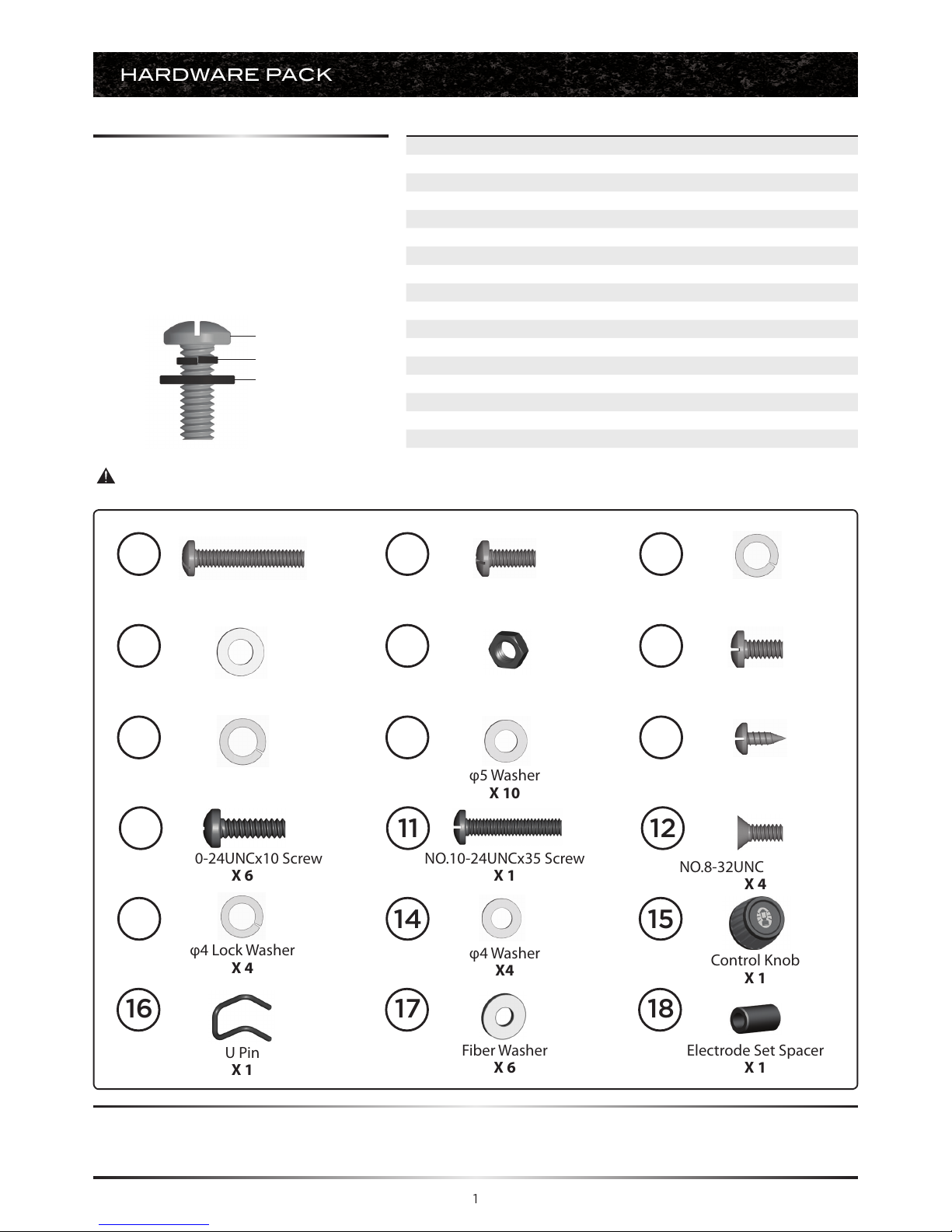
HARDWARE PACK
1/4”-20UNCx38 Screw
X 8
φ7 Washer
X 24
ST4.2x10 Tapping Screw
X 4
1/4”-20UNCx16 Screw
X 16
1/4”-20UNC Nut
X 6
Fiber Washer
X 6
Electrode Set Spacer
X 1
φ5 Lock Washer
X 10
NO.10-24UNCx10 Screw
X 6
NO.10-24UNCx35 Screw
X 1
φ7 Lock Washer
X 18
NO.10-24UNCx13 Screw
X 10
φ5 Washer
X 10
NO.8-32UNCx10 Screw
X 4
φ4 Lock Washer
X 4
1
2
3
4 5
16 17 18
6
7
8 9
10
11 12
13 14 15
Control Knob
X 1
U Pin
X 1
φ4 Washer
X4
No. Description Part Number Qty.
1 1/4"-20UNCx38 Screw 20120-13038-250 8
2 1/4"-20UNCx16 Screw 20120-13016-250 16
3 φ7 Lock Washer 41400-07000-250 18
4 φ7 Washer 40300-07000-250 24
5 1/4"-20UNC Nut 30220-13000-250 6
6 NO.10-24UNCx13 Screw 20124-10013-250 10
7 φ5 Lock Washer 41400-05000-250 10
8 φ5 Washer 40300-05000-250 10
9 ST4.2X10 Tapping Screw 22500-42010-137 4
10 NO.10-24UNCx10 Screw 20124-10010-250 6
11 NO.10-24UNCx35 Screw 20124-10035-250 1
12 NO.8-32UNCx10 Screw 20132-08010-250 4
13 φ4 Lock Washer 41400-04000-250 4
14 φ4 Washer 40300-04000-250 4
15 Control Knob G522-C700-9000 1
16 U Pin G350-0026-9000 1
17 Fiber Washer G501-0054-9100 6
18 Electrode set spacer, Side burner G453-0065-9000 1
TOOLS NEEDED FOR ASSEMBLY
• #2 Phillips screwdriver (long and short)
• 1/4” Slotted screwdriver (long and short)
• Adjustable wrench
• Pliers
For correct hardware assembly, always
position the lock washer between the screw
and the flat washer.
BEFORE ASSEMBLING THIS BARBECUE, READ THE INSTRUCTIONS CAREFULLY.
Assemble the barbecue on a flat, clean surface. Grill is heavy. Two people are
recommended to assemble this barbecue.
Caution:
Sheet metal can cause injury. Wear gloves when installing the grill.
Lock Washer
Flat Washer
Screw
Page 4

2
PARTS LIST (PROPANE) FOR 85-3092-0 (G52222)
Item No. Qty. Description Part No.
AA 1 Top lid assembly G522-2300-01
AB 1 Thermometer G522-0062-01
AC 2 Screw for top lid G433-0002-01
AD 2 Lid bumper, front G522-0088-01
AE 2 Lid bumper, rear G501-0066-01
BA 1 Burner box assembly G522-5300-01
BB 4 Even Heat™ burners G522-B600-01
BC 1 Carryover assembly G522-0087-01
BD 4 Even Heat™ heat distribution
plate
G522-0072-01
BE 3 Dual surface cooking grate G522-0097-01
BF 1 Warming rack G522-00D4-01
BG 1 Match holder G608-0019-01
BH 2 Even Heat™ heat distribution
plate brace
G522-0086-01
CA 1 Manifold assembly-LP G522-G900-01
CB 1 Regulator G606-0008-01
CC 1 Sear stove valve with T bracket
- LP
G522-00D9-01
CD 1 Metal hose, Sear stove G508-0024-01
CE1 1 Electronic ignition assembly G515-0030-02
CE2 1 Ignition battery cover G515-0030-01
CE3 1 Instastart™ ignition button G353-0009-01
CF 4 Electrode set, main burner G522-0020-02
CG 4 Control knob G522-B700-01
CH 1 Control panel G522-00D6-01
CI 1 Front brace G522-0025-01
CJ 1 Quick Clean™ grease tray G522-7500-01
CK 1 Quick Clean™ grease cup G416-0015-01
CL 1 Upper back panel G522-0026-01
CM 1 Heat shield G522-0041-01
CN 1 Right track G522-0043-01
CO 1 Left track G522-0027-01
CP 1 Door support rail G522-5100-01
Item No. Qty. Description Part No.
DA 1 Left Sear Stove Side Shelf G522-D800-02
DB 1 Sear Stove Support Frame G453-0063-01
DC 1 Sear Stove Burner G522-G800-01
DD 1 Electrode Set, Sear Stove G453-0058-01
DE 1 Sear Stove Lid G522-0058-01
DF 1 Sear Stove Cooking Grate G522-00D8-01
DG 1 Right Side Shelf G522-D600-01
DH 1 Sear Stove Control Knob (#15) G522-C700-01
DI 2 Sear Stove Grease Tray Rail G453-0064-01
DJ 1 Sear Stove Grease Tray G453-0059-01
EA 1 Left side panel G522-F600-01
EB 1 Right side panel G522-B900-01
EC 1 Left door assembly G522-8100-01
ED 1 Right door assembly G522-9100-01
EE 2 Door handle G522-00B8-01
EF 1 Bottom shelf-LP G522-F700-01
EG 2 Locking castor G515-0082-01
EH 2 Castor G350-0024-01
EI 2 Door magnet assembly G501-00F2-01
EJ 1 Tank Exclusion G522-0092-01
F1 1 Hardware Pack G522-B022-01
F2 1 Assembly Manual G522-M022-01
F3 1 Safe Use and Care Manual G353-M005-02
F4 1 Bottom shelf weight G412-0030-01
F5 1 Tank screw G505-0047-01
Page 5
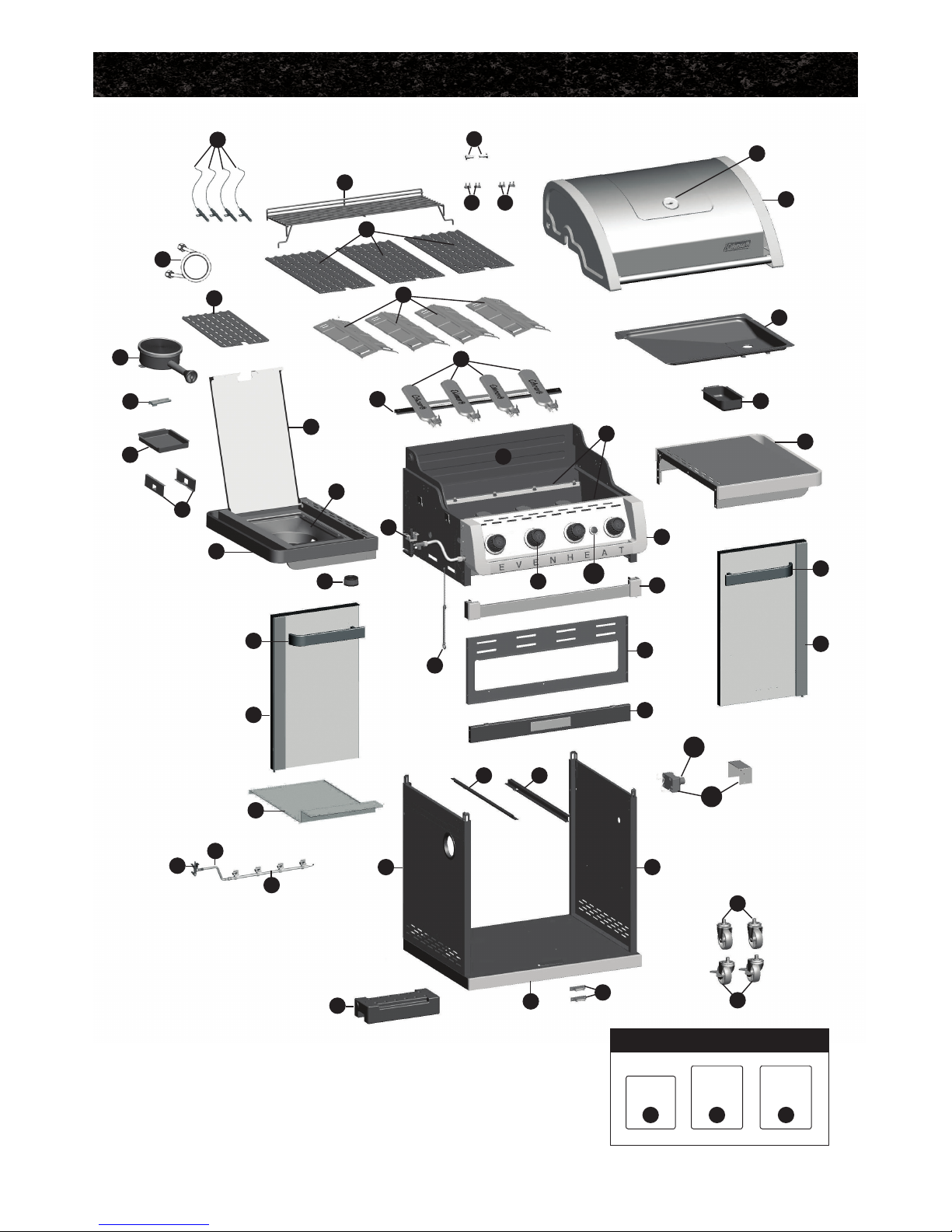
3
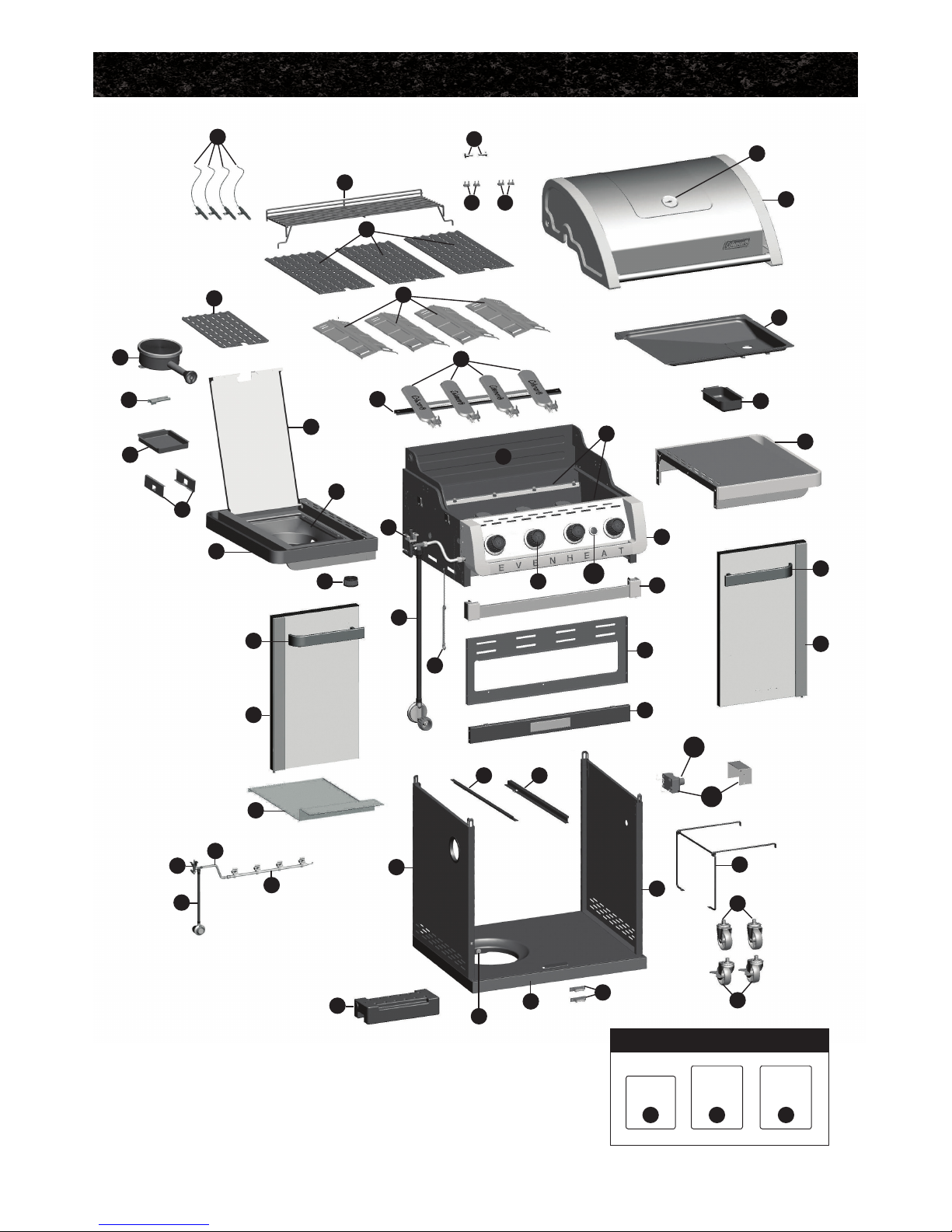
EXPLODED DIAGRAM (PROPANE) FOR 85-3092-0 (G52222)
ED
EE
CM
EB
EJ
EH
EG
EF
F5
CH
CK
DG
AA
CI
CL
CP
EI
CC
CO CN
CB
F4
EA
DA
DD
DC
DI
DJ
DE
EC
EE
DH
CB
CC
CD
CA
DF
BF
BC
DB
BA
CG
AEAD
AC
BE
BD
BB
BH
AB
CF
CJ
CE2
CE3
CE1
BG
Extras
Hardware
Pack
Assembly
Manual
Safe Use
& Care
Manual
F1 F2 F3
Page 6

4
PARTS LIST (NATURAL GAS) FOR 85-3093-8 (G52223)
Item No. Qty. Description Part No.
AA 1 Top lid assembly G522-2300-01
AB 1 Thermometer G522-0062-01
AC 2 Screw for top lid G433-0002-01
AD 2 Lid bumper, front G522-0088-01
AE 2 Lid bumper, rear G501-0066-01
BA 1 Burner box assembly G522-5300-01
BB 4 Even Heat™ burners G522-B600-01
BC 1 Carryover assembly G522-0087-01
BD 4 Even Heat™ heat distribution
plate
G522-0072-01
BE 3 Dual surface cooking grate G522-0097-01
BF 1 Warming rack G522-00D4-01
BG 1 Match holder G608-0019-01
BH 2 Even Heat™ heat distribution
plate brace
G522-0086-01
CA 1 Manifold assembly-NG G522-H100-01
CB 1 Natural Gas hose G501-0099-01
CC 1 Sear stove valve with T
bracket - NG
G522-00E1-01
CD 1 Metal hose, sear stove G508-0024-01
CE1 1 Electronic ignition assembly G515-0030-02
CE2 1 Ignition battery cover G515-0030-01
CE3 1 Instastart™ ignition button G353-0009-01
CF 4 Electrode set, main burner G522-0020-02
CG 4 Control knob G522-B700-01
CH 1 Control panel G522-00D6-01
CI 1 Front brace G522-0025-01
CJ 1 Quick Clean™ grease tray G522-7500-01
CK 1 Quick Clean™ grease cup G416-0015-01
CL 1 Upper back panel G522-0026-01
CM 1 Heat shield G522-0041-01
CN 1 Right track G522-0043-01
CO 1 Left track G522-0027-01
CP 1 Door support rail G522-5100-01
Item No. Qty. Description Part No.
DA 1 Left Sear Stove Side Shelf G522-D800-02
DB 1 Sear Stove Support Frame G453-0063-01
DC 1 Sear Stove Burner G522-G800-01
DD 1 Electrode Set, Sear Stove G453-0058-01
DE 1 Sear Stove Lid G522-0058-01
DF 1 Sear Stove Cooking Grate G522-00D8-01
DG 1 Right Side Shelf G522-D600-01
DH 1 Sear Stove Control Knob (#15) G522-C700-01
DI 2 Sear Stove Grease Tray Rail G453-0064-01
DJ 1 Sear Stove Grease Tray G453-0059-01
EA 1 Left side panel G522-F600-01
EB 1 Right side panel G522-B900-01
EC 1 Left door assembly G522-8100-01
ED 1 Right door assembly G522-9100-01
EE 2 Door handle G522-00B8-01
EF 1 Bottom shelf-NG G522-4600-01
EG 2 Locking castor G515-0082-01
EH 2 Castor G350-0024-01
EI 2 Door magnet assembly G501-00F2-01
F1 1 Hardware pack G522-B022-01
F2 1 Assembly manual G522-M022-01
F3 1 Safe use and care manual G353-M005-02
F4 1 Bottom shelf weight G412-0030-01
Page 7
DB
5
EXPLODED DIAGRAM (NATURAL GAS) FOR 85-3093-8 (G52223)
ED
EE
CM
EB
EH
EG
EF
CH
CK
DG
AA
CI
CL
CP
EI
CC
CO CN
F4
EA
DA
DD
DC
CB
DI
DJ
DE
EC
EE
DH
CC
CD
CA
DF
BF
BC
BA
CG
AEAD
AC
BE
BD
BB
BH
AB
CF
CJ
CE2
CE3
CE1
BG
Extras
Hardware
Pack
Assembly
Manual
Safe Use
& Care
Manual
F1 F2 F3
Page 8
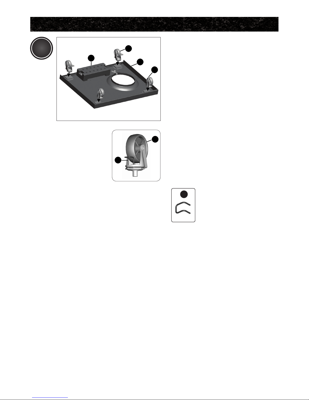
6
a. Separate the 2 dierent types of
castors: 2 locking castors (EG) and 2
regular castors (EH).
NOTE: Regular castors (EH) need to
be assembled to the front of
the bottom shelf (EF), and
locking castors (EG) need to be
assembled to the back of the
bottom shelf (EF), as shown in
image A.
b. Insert the U Pin (#16) into one of the
regular castors (EH), as shown in
image B. Attach the regular castor
(EH) to the front of the bottom shelf
(EF), and use the U Pin (#16) to secure
and tighten.
Repeat for remaining 3 castors (EG &
EH).
ASSEMBLY INSTRUCTIONS
YOU WILL NEED:
1
6
16
X 1
Upside down view
F4
EH
16
Close up
EG
EF
EH
B
A
Page 9

7
Front view
Ensure that the locking castors (EG) are
firmly locked in the “ON” position before
continuing.
Assemble the left side panel (EA) and
the right side panel (EB), to the bottom
shelf (EF).
Attach the front brace (CI) to the left
and right cart side panels (EA and EB).
The top of the front brace (CI) can be
identified by two clips located on the top
left, and right side of this part.
TIP: One person should align the left
side, while the second person assembles the right side.
ASSEMBLY INSTRUCTIONS
876
YOU WILL NEED:
YOU WILL NEED:
6 7 8
Close up
Back view
X 4 X 4 X 4
3
2
876
2 3 4
X 6 X 6 X 6
EB
EF
EA
EA
EF
CI
CI
EB
Close up
EA
Page 10

8
Attach the upper back panel (CL) to
both the left and right side panels (EA &
EB).
DO NOT tighten screws until all
hardware has been positioned.
YOU WILL NEED:
ASSEMBLY INSTRUCTIONS
1 3 4
X 4 X 4 X 4
Close up
Back view
5
CL
EA
EB
BA
CL
EB
Front view
THIS STEP REQUIRES 3 PEOPLE.
DO NOT ATTEMPT ALONE.
EXTREMELY HEAVY.
Position the top lid assembly and burner
box assembly (A & B) onto the cart
assembly (C), as shown.
4
A
B
C
Page 11

9
ASSEMBLY INSTRUCTIONS
YOU WILL NEED:
a. Assemble the left and right tracks
(CO and CN) for the Quick Clean™
grease tray (CJ), as shown in figure A.
b. Both the left and right tracks (CO and
CN) should be inserted into the two
clips located on the front brace (CI), as
shown in figure B.
c. Assemble the back of the left and right
tracks (CO and CN) to the upper back
panel (CL), as shown in figure C.
Back view
Close up, front view
Close up, back view
6
C
A
CO
CN
CN
CL
CO
6 7 8
X 2 X 2 X 2
B
CI
Page 12

10
ASSEMBLY INSTRUCTIONS
Front view
Front, right side view
View inside burner box
Back, right side view
YOU WILL NEED:
2 3 4
X 2 X 2 X 2
TIP: Do not tighten until all hardware is
in place.
a. Mount the right side shelf (DG) onto
the two support brackets, located
on the right, upper side panel of the
burner box (BA).
b. Assemble the front of the right side
shelf (DG) to the control panel (CH),
as shown in figure B.
c. Assemble the right side shelf (DG)
to the upper side panel of the burner
box (BA), by positioning hardware
through the interior of the burner box,
as shown in figure C.
d. Complete the right side shelf assembly
(DG) by connecting the right side shelf
(DG) to the rear of the burner box side
panel (BA) as shown in figure D.
7
YOU WILL NEED:
YOU WILL NEED:
2
2
4
4
17
17
X 2
X 1
X 2
X 1
X 2
X 1
5
5
X 2
X 1
A
A
B
B
A
A
B
B
A
B
A
B
C
D
BA
DG
DG
CH
BA
DG
CH
BA
DG
Page 13

11
ASSEMBLY INSTRUCTIONS
Front view
Front, left side view
View inside burner box
8
A
A
B
B
YOU WILL NEED:
2 3 4
X 2 X 2 X 2
TIP: Do not tighten until all hardware is
in place.
b. Mount the left sear stove side shelf
(DA) onto the two support brackets,
located on the left, upper side panel of
the burner box (BA).
a. Assemble sear stove grease tray rails
(DI) to the sear stove support frame
(DB) located on the left sear stove side
shelf (DA) as shown in figure A.
d. Assemble the left sear stove side
shelf (DA) to the upper side panel of
the burner box (BA), by positioning
hardware through the interior of the
burner box (BA), as shown in figure D.
C
D
BA
DA
CH
DA
BA
c. Assemble the front of the left sear
stove side shelf assembly (DA) to
the control panel (CH), as shown
in figure C.
YOU WILL NEED:
2
4
17
X 2
X 2
X 2
5
X 2
A
B
B
A
BA
DI
DB
DG
DA
YOU WILL NEED:
10
X 4
Page 14

12
ASSEMBLY INSTRUCTIONS
b. Assemble the sear stove control knob
(#15) to the sear stove valve (CC).
Front, left side view
a. Remove the hardware that is
pre-assembled to the sear stove valve
(CC). Feed the sear stove valve (CC)
through the bottom of the left side
burner side shelf (DA), and re-attach
the hardware, as shown.
9
YOU WILL NEED:
15
X 1
A
CC
DA
B
15
8
Back view
A
B
e. Complete the left sear stove side shelf
assembly (DA) by connecting the side
shelf to the rear of the burner box side
panel (BA), as shown in figure E.
E
BA
DA
CC
YOU WILL NEED:
2
4
17
X 1
X 1
X 1
5
X 1
A
B
Page 15

13
YOU WILL NEED:
10
X 2
9
ASSEMBLY INSTRUCTIONS
View from underneath left side shelf
View from underneath left side shelf
View from underneath left side shelf
d. To complete assembly of the sear
stove burner (DC), align the brackets
of the sear stove burner (DC) to the
brackets located on the sear stove
grease tray rails (DI) as shown in figure
D and E. Assemble using hardware.
IMPORTANT: Make sure that the sear
stove side burner (DC) engages the
sear stove burner valve (CC) before
tightening hardware (figure F).
D
DC
DI
View from above, left side shelf
c. Position the electrode spacer (#18)
on the sear stove support frame (DB)
and then feed the sear stove electrode
(DD) through the opening on the right
side of the sear stove support frame
(DB). Assemble using hardware as
shown in figure C.
NOTE: The sear stove electrode (DD) set
can be found attached to the sear stove
valve (CC).
C
18
E
DD
DB
6
YOU WILL NEED:
18 11
X 1 X 1
F
CC
DC
DC
DI
Page 16

14
ASSEMBLY INSTRUCTIONS
9
Left side view
View from the back, left side
e. Position the sear stove cooking grate
(DF) onto the sear stove support
frame (DB).
f. Position the sear stove grease tray
(DJ) onto the sear stove grease tray
rails (DI).
G
H
b. Position the electronic ignition box
(CE1) into the heat shield (CE1)
and feed the assembly through the
opening in the right side panel (EB)
and secure using the nut.
c. Insert one “AA” battery into the
battery compartment with the positive
end facing outward, as shown. Secure
using the ignition button cover (CE2).
a. Remove the ignition battery cover
(CE2) and the plastic nut from the
electronic ignition box (CE1).
10
B
+
CE2
A
CE2
CE1
EB
DJ
DB
DI
DF
Page 17

15
ASSEMBLY INSTRUCTIONS
f. Insert the two Instastart™ ignition
button (CE3) wires into the Electronic
ignition assembly (CE1), as shown in
figure F.
e. Insert the Electrode wire, sear stove
(DD) into the Electronic ignition
assembly (CE1), as shown in figure E.
10
TIP: The Electrode Set, main burner (CF)
and the Electrode wire, side burner
(DD), can be found attached to the
control panel (CH) heat shield, as
shown in figure C.
d. Insert the four Electrode set, main
burner (CF) wires into the Electronic
ignition assembly (CE1) as shown in
figure D.
D
E
F
CE1
CE1
CE1
Control panel, right side
CF
DD
CF
CE3
ELECTRONIC IGNITION: ELECTRODE ASSEMBLY
C
CF
DD
CH
Page 18

16
ASSEMBLY INSTRUCTIONS
a. Assemble the heat shield (CM) to
the bottom of the front brace (CI) as
shown in figure A.
b. Assemble the back of the heatshield
(CM) to the upper back panel (CL), as
shown in figure B.
b. Assemble the tank exclusion (EJ)
to the right cart side panel (EB), as
shown in figure C.
YOU WILL NEED:
9
X 2
PROPANE MODEL ONLY
a. Assemble the tank exclusion (EJ) to
the bottom shelf (EF), as shown in
figure A.
11
12
YOU WILL NEED:
9
X 2
A
B
YOU WILL NEED:
12 13 14
X 2 X 2 X 2
YOU WILL NEED:
12 13 14
X 2 X 2 X 2
CI
CM
CM
CL
Front view
Back view
C
EB
B
EJ
EF
A
EJ
EF
Page 19

17
ASSEMBLY INSTRUCTIONS
Assemble the door support rail (CP) to
the left and right upper side panels (EA
and EB), as shown.
WARNING: This part may have sharp
edges. Wear protective gloves when
assembling.
Front, left side view
YOU WILL NEED:
1 3 4
X 4 X 4 X 4
Close up, front view
13
14
Assemble the door handle (EE) to the
left and right door assembly (EC and ED)
as shown in figure A and B.
YOU WILL NEED:
6 7 8
X 4 X 4 X 4
A
EA
CP
EB
B
CH
EA
CP
A
B
EE
EC
EE
EC
Page 20

18
ASSEMBLY INSTRUCTIONS
PROPANE MODEL SHOWN
a. Assemble the right door assembly
(ED), to the bottom shelf (EF) by
inserting the fixed pin (bottom of
door) into the hole provided (figure B).
b. Assemble the top of the door
assembly (ED) to the door support rail
(CP), by pressing in the door support
pin and aligning with the hole located
on the top right corner of the door.
TIP: Use a paint scraper to press-in
the support pin, while the second
person aligns the door. The support
pin will lock into position when the
door is assembled correctly.
c. Repeat steps a, and b for the left door
assembly (EC).
Top of door
Bottom of door
15
B
ED
EF
EB
C
ED
CP
A
ED
CP
EF
Page 21

19
ASSEMBLY INSTRUCTIONS
a. Position the Quick Clean
TM
grease tray
(CJ) onto the right and left tracks (CN
and CO), as shown.
b. Position the Quick Clean™ grease cup
(CK) in position under the under the
Quick Clean™ grease tray (CJ).
17
CJ
CK
Back view
Position the Even HeatTM heat
distribution plates (BD) into the burner
box (BA) as shown.
16
C
BD
BH
B
BH
BD
A
BD
Page 22

20
FOR PROPANE MODEL ONLY.
For natural gas model, follow step 21.
a. Feed the regulator (CB) through the
opening on the left side panel (EA).
c. Attach the regulator (CB) coupling nut
to the propane cylinder valve.
ATTENTION:
DO NOT STORE EXTRA PROPANE
TANKS WITHIN BBQ CART.
b. Position the 20 lb propane tank onto
the bottom shelf (EF), and secure
using the tank screw (F5) (already
attached) located on the underside of
the bottom shelf, as shown in figure B.
19
CB
CI
EA
A
B
C
a. Assemble the warming rack (BF) by
inserting the three fixed pins into the
three holes provided on the burner
box back panel (BA), as shown in
Figure A.
b. Place the cooking grates (BE) into the
burner box (BA), as shown in figure A.
18
A
BF
BE
F5
ASSEMBLY INSTRUCTIONS
Page 23

ASSEMBLY INSTRUCTIONS
FOR NATURAL GAS MODEL ONLY.
Attach the natural gas hose (CB) to the
sear stove valve (CC), as shown.
ATTENTION: In order to complete
installation of your Natural Gas BBQ a
½” or 3/8” adapter may be required to
connect your BBQ’s Natural gas hose
to your home gas supply. Contact
your natural gas supplier to purchase
the necessary part.
www.colemanbbqs.com
20
CC
CB
Page 24

ADDITIONAL WARNINGS
POSITION YOUR BARBECUE
WARNING HOT SURFACES:
You have now completed the Assembly of your COLEMAN® EVEN HEAT™ BARBECUE.
NEXT STEPS:
1. Position your BARBECUE
2. Read SAFE USE & CARE MANUAL
3. Perform Grill Safety Check-list
WARNING:
FOR YOUR FAMILIES SAFETY,
DO NOT ATTEMPT TO LIGHT
THIS BBQ UNTIL YOU HAVE
REVIEWED PAGES 4-7 OF
THE COLEMAN SAFE USE &
CARE MANUAL. ALL SAFETY
AND LEAK TESTS MUST BE
PERFORMED BY THE END USER,
PRIOR TO LIGHTING THIS BBQ.
Always confirm that this Barbecue is not positioned under a combustible object
(e.g., an awning or umbrella) or in a covered area (e.g., porch or gazebo) before
lighting it, to prevent a possible fire.
Always confirm that this Barbecue is not positioned under the overhang of a house,
a garage or other structure before lighting it. An overhang will serve to deflect
flare-ups and radiate heat into the structure itself, which could result in a fire.
Always confirm that this Barbecue is positioned more than 36” (91.4cm) away from
any combustible materials or surfaces before lighting it, and that no gasoline or other
volatile substances are stored in the vicinity of this Barbecue. The temperature of
a grease fire or of the radiated heat might otherwise be sucient to ignite nearby
combustibles or volatile substances. Do not position near windows, siding, or fencing.
Always locate the Barbecue where there will be ample combustion and ventilation air,
but never position it in the direct path of a strong wind.
!
!
!
Page 25

Page 26

Manufactured by Winners Products Engineering Ltd.
Coleman®, and are registered trademarks of
The Coleman Company, Inc. used under license. ©2014 The Coleman Company, Inc.
Join the conversation
facebook.com/colemangrills twitter.com/colemangrills
www.colemanbbqs.com
 Loading...