

Coleman Echelon 13 Seer A C3B Series, Echelon 13 Seer H C3B Series, AC3B SERIES, HC3B SERIES User's Information Manual
Page 1
USER’S INFORMATION
LISTED
U
N
I
T
A
R
Y
H
E
A
T
P
U
M
P
T
E
Q
U
I
P
M
E
N
R
S
E
C
T
I
O
N
S
A
T
I
O
N
E
R
T
I
F
I
C
C
O
F
D
S
T
A
N
D
A
R
I
A
R
2
4
0
M
A
N
U
F
A
C
T
U
R
E
R
C
E
R
T
I
F
I
E
D
C
L
Y
O
M
P
I
N
G
T
O
A
R
I
A
S
Certification applies only
when the complete
system is listed
with ARI.
Certification applies only
when the complete
system is listed
with ARI.
R
N
E
M
P
I
U
Q
E
T
Y
R
A
T
I
N
U
0
1
2
A
R
I
R
A
D
N
A
T
S
D
I
S
N
O
T
C
E
S
F
O
C
C
I
F
I
T
R
E
N
O
I
T
A
H
T
I
W
C
G
N
I
Y
L
P
M
O
S
A
I
R
A
O
T
D
E
I
F
I
T
R
E
C
R
E
R
U
T
C
A
F
U
N
A
M
C
-
G
N
I
N
O
I
T
I
D
N
O
R
I
A
ISO 9001
Certified Quality
Management System
MANUAL
ECHELON
R-410A OUTDOOR SPLIT-SYSTEM
AIR CONDITIONING OR HEAT PUMP
MODELS: 13 SEER AC3B / HC3B SERIES 1-1/2 TO 5 T ONS
CONTACT INFORMATION . . . . . . . . . . . . . . . . . . . . . . . . . . . . . . . .1
SAFETY . . . . . . . . . . . . . . . . . . . . . . . . . . . . . . . . . . . . . . . . . . . . . . . .1
THERMOSTATS . . . . . . . . . . . . . . . . . . . . . . . . . . . . . . . . . . . . . . . . .1
YOUR KEY TO COMFORT . . . . . . . . . . . . . . . . . . . . . . . . . . . . . . . 1
COOLING ONLY . . . . . . . . . . . . . . . . . . . . . . . . . . . . . . . . . . . . . . . .1
COOLING AND HEATING (HEAT PUMP) . . . . . . . . . . . . . . . . . . . .2
MANUAL CHANGE-OVER . . . . . . . . . . . . . . . . . . . . . . . . . . . . . . . . 2
PROGRAMMABLE ELECTRONIC THERMOSTATS . . . . . . . . . . . . .2
FAN OPERATION SELECTION . . . . . . . . . . . . . . . . . . . . . . . . . . . . 2
START-UP . . . . . . . . . . . . . . . . . . . . . . . . . . . . . . . . . . . . . . . . . . . . . .2
POWER FAILURE . . . . . . . . . . . . . . . . . . . . . . . . . . . . . . . . . . . . . . 2
CONTACT INFORMATION
• Go to website at www.colemanac.com click on “about us”, then click on “contact us” and follow the instructions.
• Contact us by mail:
Congratulations . . .
On your purchase of one of the most versatile comfort conditioning
systems available in the industry today. This high efficiency system
has been precision designed, manufactured of high quality materials
and has passed many vigorous inspections and tests to ensure years of
satisfactory service.
This booklet is meant to increase your understanding of your system,
tell you how to operate it efficiently and how to obtain the greatest
measure of comfort at the lowest operating expense. Please read this
booklet thoroughly.
We appreciate your interest in our product and your decision to purchase our system. Enjoy your comfort.
The manufacturer recommends that the user read all sections of this manual and keep the manual for future reference.
SECTION I: SAFETY
This product must be installed and serviced by a qualified
installer or service agency. Improper installation, adjustment,
alteration, service or maintenance can cause injury or property
damage.
TABLE OF CONTENTS
SYSTEM OPERATION . . . . . . . . . . . . . . . . . . . . . . . . . . . . . . . . . . . . .2
MANUAL CHANGE-OVER THERMOSTAT . . . . . . . . . . . . . . . . . . .2
ELECTRONIC THERMOSTAT . . . . . . . . . . . . . . . . . . . . . . . . . . . . .3
CARE OF SYSTEM . . . . . . . . . . . . . . . . . . . . . . . . . . . . . . . . . . . . . . .3
COIL CARE . . . . . . . . . . . . . . . . . . . . . . . . . . . . . . . . . . . . . . . . . . . .3
SERVICE CALLS . . . . . . . . . . . . . . . . . . . . . . . . . . . . . . . . . . . . . . .3
FILTER CARE . . . . . . . . . . . . . . . . . . . . . . . . . . . . . . . . . . . . . . . . . .3
CLEARANCES . . . . . . . . . . . . . . . . . . . . . . . . . . . . . . . . . . . . . . . . .3
PARTS INFORMATION . . . . . . . . . . . . . . . . . . . . . . . . . . . . . . . . . .3
EXTENDED WARRANTY . . . . . . . . . . . . . . . . . . . . . . . . . . . . . . . . .3
SOME EFFICIENCY DO’S & DON’TS . . . . . . . . . . . . . . . . . . . . . . . . .3
LIMITED WARRANTY . . . . . . . . . . . . . . . . . . . . . . . . . . . . . . . . . . . . .4
York International
Consumer Relations
5005 York Drive
Norman, OK 73069
SECTION II: THERMOSTATS
YOUR KEY TO COMFORT
Though thermostats may vary widely in appearance they are all
designed to perform the same basic function, to control the operation of
your air conditioning or heat pump system. Regardless of size or shape,
each thermostat will feature a temperature indicator; a dial, arm or push
button for selection of the desired temperature; a fan switch to choose
the indoor fan operation; and a comfort switch for you to select the system mode of operation.
Only approved thermostats have been tested and are fully compatible
with this equipment. Please be aware that many different thermostats
operate on batteries or “power stealing” principals. These types of thermostats can not be supported as trouble free when used with this product.
The following illustrations and discussion will aid you to determine
which type of thermostat you have for your system.
A complete operating instruction is provided by the manufacturer for
each thermostat. Familiarize yourself with its proper operation to obtain
the maximum comfort with a minimum of energy consumption.
COOLING ONLY
If your air conditioning system is designed to provide cooling only (AC),
with no capability for heating operation (heat pump), a one-stage cooling only thermostat, with a manual, one-position “Cool” and “Off” comfort switch is all that is required for system operation.
NOTE: If you have an independent heating system (with a separate
thermostat), always be sure the heating control is turned “Off”
before turning on the cooling system.
106468-CUM-D-0409
Page 2
106468-CUM-D-0409
COOLING AND HEATING (HEAT PUMP)
If your system has been designed to allow both cooling and heating
operation, you may have either a manual change-over type, or a programmable electronic type thermostat.
MANUAL CHANGE-OVER
Manual change-over simply means that the comfort switch must be
manually positioned every time you wish to switch from the cooling to
heating or heating to cooling modes of operation.
SECTION III: PROGRAMMABLE
ELECTRONIC THERMOSTATS
The computerized electronic thermostat is actually a sophisticated electronic version of a manual change-over type. This thermostat includes
features which allow “set-back” temperature variations for periods of
sleep, or while you are away during the day, and means energy savings
for you. The thermostat also features a digital clock.
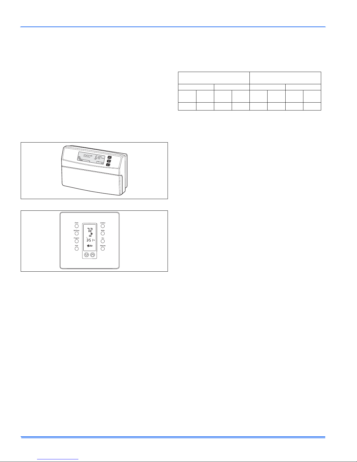
FIGURE 1: PROGRAMMABLE ELECTRONIC THERMOSTAT
SECTION IV: START-UP
The maximum and minimum conditions for operation must be observed
to assure a system that will give maximum performance with minimum
service.
TABLE 1:
Cool Heat Cool Heat °WB
The comfort control switch is assumed to be in the “OFF” position. If the
main power supply to the outdoor and indoor units is off, turn the appropriate disconnects to the “ON” position. Place the system into operation
as follows:
1. Set temperature adjustment to the desired temperature on your
COOLING - The higher the setting, the lower the amount of energy consumed. Federal Guidelines recommend a setting of 78°F.
HEATING - The lower the setting, the lower the amount of energy consumed. Federal guidelines recommend a setting of 65°F or lower.
NOTE: If your cooling and heating temperature adjustments are sepa-
2. After considering “Fan Operation Selection” above, select and set
3. Move the comfort control switch to the desired mode of operation
POWER FAILURE
When accidents, wind storms, etc. disrupt electrical power supply to
your house, switch thermostat to “OFF” position.
APPLICATION LIMITATIONS
Air Temperature DB at
Outdoor Coil, °F
Min. Max. Min. Max.
50 -10 115 75 57
1.
Operation below this temperature is permissible for a short
period of time, during morning warm-up.
thermostat.
rate, be sure to set both.
the fan operation mode you desire.
(Cooling or Heating) found on your particular thermostat.
Air Temperature DB at
Indoor Coil, °F
°DB
°WB
Cool
Heat
50
Cool
1
72 80
°DB
Heat
FIGURE 2: PROGRAMMABLE ELECTRONIC THERMOSTAT
FAN OPERATION SELECTION
A multi-position fan switch allows you to choose the type of fan operation of the indoor fan.
AUTO
With the thermostat fan switch set to “AUTO”, the fan will run intermittently as required for either heating or cooling. This position will provide
the lowest operating cost. If you purchased one of our thermostats, they
have an Intelligent fan mode which continually circulates the air during
occupied modes or when you are at home, and can cycle the fan during
unoccupied mode or during the night while you sleep to further conserve energy.
ON
CONTINUOUS FAN OPERATION: With the thermostat fan switch set to
“ON”, the indoor fan will not shut off. However, the cooling (AC) or heating (heat pump) systems will still operate as required by room temperatures. This provides continuous air filtering and more even temperature
distribution to all conditioned spaces.
FAN ONLY OPERATION: On moderate days, usually during spring and
fall, when neither heating nor cooling is required, you may want to run
only the fan to ventilate, circulate and filter the air in your home or building. Set the comfort control switch to “OFF” and the fan switch to “ON”.
Be sure to return the switches to their original positions for normal operation.
SECTION V: SYSTEM OPERATION
MANUAL CHANGE-OVER THERMOSTAT
COOLING YOUR HOME: With the comfort control switch in the
“COOL” position, the system will operate as follows: When the indoor
temperature rises above the level indicated by the temperature adjustment setting, the system will start. The outdoor unit will operate and the
indoor fan will circulate the cooled, filtered air. When the room temperature is lowered to the setting selected, the system will shut off.
HEATING YOUR HOME: If your system includes a heating unit and the
comfort control switch is in the “HEAT” position, the system will operate
as follows: When the indoor temperature drops below the level indicated by the temperature adjustment setting, the system will start. The
heating system will operate and the indoor fan will circulate the filtered
air. When the room temperature rises to the setting selected, the system will shut off. Whether heating or cooling, the fan will continue to
operate if the fan switch was set in the “ON or Intelligent” position. The
“AUTO” setting on the fan switch will allow the fan to shut off when your
system does.
2 Unitary Products Group
Page 3

106468-CUM-D-0409
ELECTRONIC THERMOSTAT
The computerized electronic thermostat, when programmed, will function automatically to operate the system as follows: When the indoor
temperature rises above the higher (COOL) setting, the outdoor unit will
operate and the indoor fan will circulate the cooled, filtered air. When
the room temperature is lowered to the selected level, the system will
shut off. The indoor fan will either shut off or run continuously, depending upon your choice of fan switch setting. When the indoor temperature drops below the lower (HEAT) setting, the heating system will
operate, and the indoor fan will circulate the heated, filtered air. When
the indoor temperature rises to the selected setting, the system will shut
off.
The indoor fan will either shut off or run continuously, depending upon
your choice of fan switch setting.
SECTION VI: CARE OF SYSTEM
It is strongly recommended that regular periodic preventative maintenance be performed on this equipment. The person most familiar with
the equipment in your H.V.A.C. system is a dealer. The dealer can
ensure your maintenance program meets the conditions of the Warranty”, maximize the efficiency of the equipment, and service your unit
within the federally mandated guidelines with regard to unlawful discharge of refrigerants into the atmosphere.
COIL CARE
Keep the outdoor unit free of foliage, grass clippings, leaves, paper, and
any other material which could restrict the proper air flow in and out of
the unit. The coil may be vacuumed to remove any debris from between
the fins. If the coil becomes excessively dirty, turn the main disconnect
switch to “Off” and wash the coil with your garden hose. Avoid getting
water into the fan motor and control box. Flush dirt from base pan after
cleaning the coil.
SERVICE CALLS
There are a few instances where the user can avoid unnecessary service calls. If unit stops functioning properly check the following items
before calling your servicing dealer:
1. Indoor section for dirty filter.
2. Outdoor section for leaf or debris blockage. Eliminate problem,
turn off the thermostat for 10 seconds and attempt start. Wait 5
minutes. If system does not start, call your servicing dealer.
Your system contains environmentally friendly refrigerant
R-410A, which operates at high pressures. You may be in
danger if you try to make an attempt to repair your unit.
Please contact your local dealer.
FILTER CARE
Inspect the air filter(s) at least once a month. If they are dirty, wash
reusable filters with a mild detergent per manufacturer’s recommendations. Replace disposable filters with new filters. Install the clean filters
with “air flow” arrow in the same direction as the air flow in yo ur duct.
Filters should be clean to assure maximum efficiency and adequate air
circulation.
CLEARANCES
The minimum clearances shown below must be maintained should any
patio or yard improvements be done around the outdoor unit.
TOP 48" SIDES* 24"
SIDES, REAR 12" FRONT 12"
* Service Access Panel
PARTS INFORMATION
Replacement parts are available from local contractor/dealer or the
nearest distribution center.
EXTENDED WARRANTY
Special warranty packages (called Performance Promise) are available
through your contractor. These packages reduce the potential cost of
service calls following the first year of operation on your cooling (or
heating/cooling) system.
SECTION VII: SOME EFFICIENCY DO’S &
DON’TS
DON’T heat or cool unused household area. Reduce supply and return
air flow to a minimum in areas which are not living spaces (storage
rooms, garages, basements, etc).
DON’T be a “thermostat jiggler”. Moving your thermostat setting will not
make your system heat or cool any faster. Adjust your thermostat to a
comfortable setting and leave it there.
DON’T restrict air circulation. Placing furniture, rugs, etc. in such a way
that they interfere with air vents will make your system work harder to
achieve a comfortable temperature level. This requires more energy,
which means greater cost to you.
DON’T heat or cool when you are away. If you are going to be away for
a day or more, re-adjust your thermostat accordingly. Your furniture is
far less demanding than you are when it comes to comfort levels. However, don’t expect the system to restore comfort conditions immediately
upon returning home. It will take a little time.
DON’T locate lamps or other heat-producing appliances (radios, TV’s,
heaters, etc.) near your thermostat. The heat from these items will give
your thermostat “false information” about the temperature in the room.
DO select a comfortable thermostat setting, but keep in mind that moderation in temperature selection will save energy.
DO turn on your kitchen exhaust fan when cooking and your bathroom
exhaust fan when showering. Also, make sure your clothes dryer is
properly vented. If these items are neglected, an excess heat and
humidity condition may be created, causing your air conditioning system to run longer.
DO set your thermostat a few degrees lower than normal several hours
before entertaining a large group of people in a relatively small area.
People give off a considerable amount of heat and moisture in a closed
area.
DO keep drapes and venetian blinds closed when practical. These
items provide insulation against heat loss/gain.
DO contact a qualified service person to make repairs or adjustments to
your system. He has been trained to perform this service.
Unitary Products Group 3
Page 4

Limited Warranty
Johnson Controls Unitary Products (hereinafter “Company”) warrants this product to be free from defects in factory workmanship and material under normal use and
service and will, at its option, repair or replace any parts, without charge, subject to the exclusions below, that prove to have such defects according to the terms outlined
on this warranty. This warranty covers only the equipment described by the Product Model Number and Serial Number on the equipment or listed on the Warranty Registration Card and applies only to products installed in the United States or Canada.
FOR WARRANTY SERVICE OR REPAIR:
Contact the installer or a Company dealer. You may find the installer’s name on this page or on the equipment. You can also find a Company dealer online at
www.yorkupg.com. For help finding a servicing dealer, contact: Johnson Controls Unitary Products, Consumer Relations, 5005 York Drive, Norman, OK 73069. Or, by
phone 877-874-7378. All warranty service or repair will be performed during regular business hours, Monday through Friday 9:00am-5:00pm.
PRODUCT MODEL NO. ________________________ INSTALLATION DATE _______________________
NIT SERIAL NO. ___________________________ I NSTALLING DEALER _____________________________
U
FOR PRODUCT REGISTRATION: For your benefit and protection, return the Warranty Registration Card to Company promptly after installation. This will initiate the
warranty period and allow us to contact you, should it become necessary. This warranty extends only to the original consumer purchaser and is nontransferable. For this
warranty to apply, the product must be installed according to Company recommendations and specifications, and in accordance with all local, state, and national codes;
and the product must not be removed from its place of original installation. The warranty period for repair or replacement parts provided hereunder shall not extend beyond
the warranty period stated below. In the absence of a recorded Warranty Registration Card, the warranty period will begin upon product shipment from Company. If you
are unaware of the date the warranty became effective, contact Company at 877-874-7378 or visit www.upgproductregistration.com. You can register your product online
at www.upgproductregistration.com or by returning the Warranty Registration Card on the back page of this packet.
The warranty period in years, depending on the part and the claimant, is as shown in the chart below.
Air contionner / Heat pump
THGD 5 years 5 years
CMB, CZB, CZE, TCGF, YCHD, YMB, YZB, YZE, YZH, TCGD, THRD, YHJD, YHJF
AL3A, AL3B, AL5B, HL3A, HL3B, HL5B, HL8B, TCGD, LHJD, LHJF
AC3A, AC3B, AC5B, HC3A, HC3B, HC5B, HC8B, TCGD, CHJD, CHJF
1
All 3 phase condensing units have 5-year compressor and 1-year parts.
†To qualify for the extended 10-year parts warranty, the unit must be registered online at www.upgregistration.com within 90 days of installation. (R-410A units only)
Company strongly recommends regular periodic preventative maintenance on this equipment. The person most familiar with the equipment in your HVAC system is a
Company dealer. The Company dealer can ensure your maintenance program meets the conditions of the “Company Warranty”, maximize the efficiency of the equipment,
and service your unit within the mandated guidelines with regard to unlawful discharge of refrigerants into the atmosphere.
EXCLUSIONS
This warranty does not cover any:
S
1.
hipping, labor, or material charges.
2. Damages resulting from transportation, installation, or servicing.
D
3.
amages resulting from accident, abuse, fire, flood, alteration, or acts of God (tampering, altering, defacing or removing the product serial number will serve to void
this warranty).
4.
amages resulting from use of the product in a corrosive atmosphere.
D
5. Damages resulting from inadequacy or interruption of electrical service or fuel supply, improper voltage conditions, blown fuses, or other like damages.
6.
leaning or replacement of filters.
C
7. Damages resulting from failure to properly and regularly clean air and/or water side of condenser and evaporator.
8.
amages resulting from: (I) freezing of condenser water or condensate; (II) inadequate or interrupted water supply; (III) use of corrosive water; (IV) fouling or
D
restriction of the water circuit by foreign material or like causes.
9.
amages resulting from operation with inadequate supply of air or water.
D
10. Damages resulting from use of components or accessories not approved by Johnson Controls Unitary Products (vent dampers, etc.).
11.
ncrease in fuel or electric cost.
I
1
compressor other parts
Residential applications only
10 years 5 or 10 years†
THIS WARRANTY IS IN LIEU OF ALL OTHER WARRANTIES, EXPRESSED OR IMPLIED, INCLUDING THE IMPLIED WARRANTIES OF MERCHANTABILITY AND FITNESS FOR A PARTICULAR PURPOSE.
SOME STATES DO NOT ALLOW THE DISCLAIMER OF IMPLIED WARRANTY, SO THAT THE ABOVE DISCLAIMER MAY NOT APPLY TO YOU.
SOME STATES ALLOW ONLY A PARTIA
DURATION OF THE EXPRESS WARRANTY. IN SUCH STATES, THE DURATION OF IMPLIED WARRANTIES IS HEREBY EXPRESSLY LIMITED TO THE
DURATION OF THE EXPRESS WARRANTY ON THE FACE HEREOF.
IN NO EVENT, WHETHER AS A RESULT OF BREACH OF WARRANTY OR CONTRACT, TORT (INCLUDING NEGLIGENCE) STRICT LIABILITY OR
OTHERWISE, SHALL JOHNSON CONTROLS UNITARY PRODUCTS BE LIABLE FOR SPECIAL, INCIDENTAL, OR CONSEQUENTIAL DAMAGES, INCLUDING BUT NOT LIMITED TO LOSS OF USE OF THE EQUIPMENT OR ASSOCIATED EQUIPMENT, LOST REVENUES OR PROFITS, COST OF SUBSTITUTE EQUIPMENT OR COST OF FUEL OR ELECTRICITY. THE ABOVE LIMITATIONS SHALL INURE TO THE BENEFIT OF JOHNSON CONTRO
NITARY PRODUCTS’ SUPPLIERS AND SUBCONTRACTORS.THE ABOVE LIMITATION ON CONSEQUENTIAL DAMAGES SHALL NOT APPLY TO
U
INJURIES TO PERSONS IN THE CASE OF CONSUMER GOODS.
SOME STATES DO NOT ALLOW THE EXCLUSION OR LIMITATION OF LIABILITY FOR CONSEQUENTIAL OR INCIDENTAL DAMAGES, OR FOR
STRICT LIABILITY IN TORT, SO THAT THE ABOVE EXCLUSIONS AND LIMITATIONS MAY NOT APPLY TO YOU.
JOHNSON CONTROLS UNITARY PRODUCTS DOES NOT ASSUME, OR AUTHORIZE ANY OTHER PERSON TO ASSUME FOR JOHNSON CONTROLS
UNITARY PRODUCTS, ANY OTHER LIABILITY FOR THE SALE OF THIS PRODUCT.
THIS WARRANTY GIVES YOU SPECIFIC LEGAL RIGHTS. YOU MAY ALSO HAVE OTHER RIGHTS WHICH VARY FROM STATE TO STATE.
MITATION ON IMPLIED WARRANTIES TO LIMIT THE DURATION OF IMPLIED WARRANTIES TO THE
L LI
REV 09/09
LS
 Loading...