

Page 1
Alton Industries Ltd. Group
1 year Limited Warranty
Alton Industries Group will repair or replace any defective materials
due to craftsmanship of the product. This warranty does not cover
any problem caused by misuse, abuse, accidents or acts of God,
such as floods or hurricanes. Consequential and incidental
damages are not covered under this warranty. Coverage
terminates if you sell or otherwise transfer the ownership.
Replacement parts and service are available from your nearest
authorized Service Center. If the need arises, contact Service
Center as listed below. When consulting with a Service Center,
refer to the model number and serial number located on the
serial label of the generator. Proof of purchase is required for all
transactions and a copy of your sales receipt may be requested.
Record the model number, serial number, and date purchased
in the spaces provided below. Retain your sales receipt and this
manual for future reference.
Model No. Serial No. Date Purchased
When needing service or replacement parts, please call
We reserve the right to repair or replace the product at our discretion.
However, if the product is no longer available due to discontinuation, we
may replace the product with one of similar but not exact features.
This warranty gives you specific legal rights. You may have other
rights which vary from state to state.
IMPORTANT: READ MANUAL BEFORE USING!
Made in China
Toll-Free-Helpline: 1-866-393-3968
Colemanƻ
R
and are registered trademarks of
The Coleman Company, Inc. used under license. ƻC2010 The
Coleman Company, Inc.
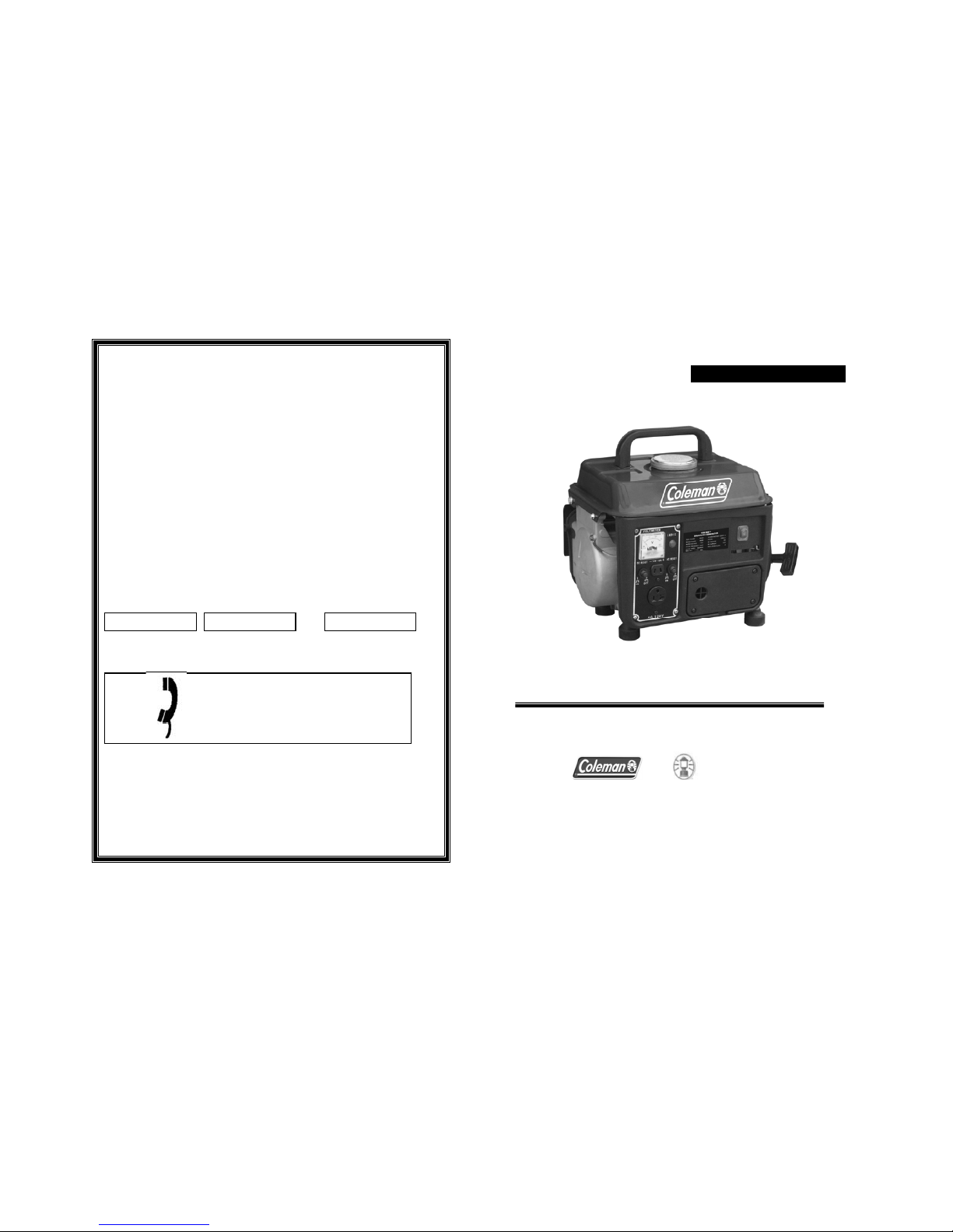
1000W 120V AC & 12V DC
GENERATOR
-24-
In U.S.A.
Toll Free
1-866-393-3968
Fax 1-817-442-5402
ITEM# CM04101
Page 2
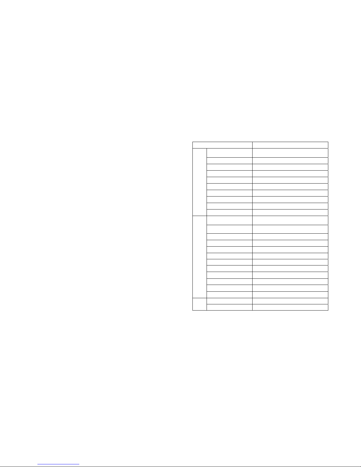
TABLE OF CONTENTS
SAFETY GUIDELINES&INFORMATION --------------- 2~7
PRE-OPERATION PREPARATION ------------ 8
STARTING THE ENGINE -------------------- 9 thru 10
CONNECTION -----------------------------------------------11
STOPPING THE ENGINE -----------------------------12
PERIODIC MAINTENANCE -----------------13 thru15
TROUBLESHOOTING ------------------------16 thru 17
DC APPLICATION -----------------------------------------17
EXPLODED VIEW - GENERATOR-----------------18
PARTS LIST - GENERATOR --------------------------19
EXPLODED VIEW - Control Panel ----------------20
PARTS LIST - Control Panel ------------------------- 21
SCHEMATIC
--------------------------------------------------22
APPLICABILITY
---------------------------------------------23
WARRANTY----------------------------------------------------24
(X) APPLICABILITY
MODEL 04101
GENERATOR
Type
Brushless, Revolving Field, Self-exciting,
2-poles, Single phase
Voltage Regulator Condenser Type
Max. Output 1000W
Rated Output 900W
AC Voltage 120V
Rated Current 7.5A
Frequency 60Hz
Phase single
Power Factor cos=1.0
Performance Class G1
ENGINE
Type
Air-cooled 2-stroke, Single Cylinder
Oil-mixed Fuel Engine
Displacement 71cc
Stroke 45×40mm
Max. Output 2.0HP/3600rpm
Fuel Regular Automobile EURO95/98
Oil 2-stroke small engine oil
Fuel/Oil Mix Ratio 40:1
Fuel tank Capacity 1.1 gallon
Starting System Recoil Starter
Ignition system C.D.I
Air Cleaner Type Sponge Element
Certificate EPA
UNIT
Length×Width×Height 16.93* 14.96*14.96 in
Net Weight 36.5lbs
-23-
Page 3
SAFETY GUIDELINES: READ
THIS MANUAL THOROUGHLY
If any portion of this manual is not under stood,
contact the toll free Coleman® Customer
Service line at 1-855-900-2653 for starting,
operating and servicing proced ures.
The operator is responsible for proper and safe
use of the equipment. We strongly recommend
that the operator read this manual and
thoroughly understand all instruct ion s bef ore
using the equipment. We also strongly
recommend instructing other users to properly
start and operate the unit. This prepares them if
they need to operate the equipment in an
emergency.
The generator can operate safely, efficiently and
reliably only if it is properly located, operated
and maintained. Before operating or servicing
the generator:
• Become familiar with and strictly adhere
to all local, state and national codes and
regulations.
• Study all safety warnings in this manual
and on the product carefully.
• Become familiar with this manual and
the unit before use.
The manufacturer cannot anticipate every
possible circumstance that might involve a
hazard. The warnings in this manual, and on
tags and decals affixed to the unit are, therefore,
not all inclusive.
If using a procedure, work method or operating
technique that the manufacturer does not
specifically recommend, ensure that it is safe for
others. Also make sure the procedure, work
method or
operating technique utilized does not render the
generator unsafe.
THE INFORMATION CONTAINED HEREIN
WAS BASED ON MACHINES IN PRODUCTION
AT THE TIME OF PUBLICATION. WE
RESERVE THE RIGHT TO MODIFY THIS
MANUAL AT ANY TIME.
SAFETY RULES
Throughout this publication, and on tags and
decals affixed to the generator, DANGER,
WARNING, CAUTION and NOTE blo c ks are
used to alert personnel to special instructions
about a particular operation that may be
hazardous if performed incorrectly or carelessly.
Observe them carefully. Their definitions are as
follows:
Indicates a hazardous situation or action
which, if not avoided, will result in death or
serious injury.
Indicates a hazardous situation or action
which, if not avoided, could result in death or
serious
injury.
CAUTION!
Indicates a hazardous situation or action
which, if not avoided, could result in minor
or moderate injury.
NOTE:
Notes contain additional information
important to a procedure and will be found
within the regular text body of this manual.
These safety warnings cannot eliminate the
hazards that they indicate. Common sense and
strict compliance with the special instructions
while performing the action or service are
essential to preventing accidents.
Four commonly used safety symbols
accompany the DANGER, WARNING and
CAUTION blocks. The type of information each
indicates is as follows:
This symbol points out
important safety information
that, if not followed, could endanger
personal safety and/or property of
others.
This symbol points out
potential explosion hazard.
This symbol points out
potential fire hazard.
This symbol points out
potential electrical shock
hazard.
- 2 - - 3 -
Page 4
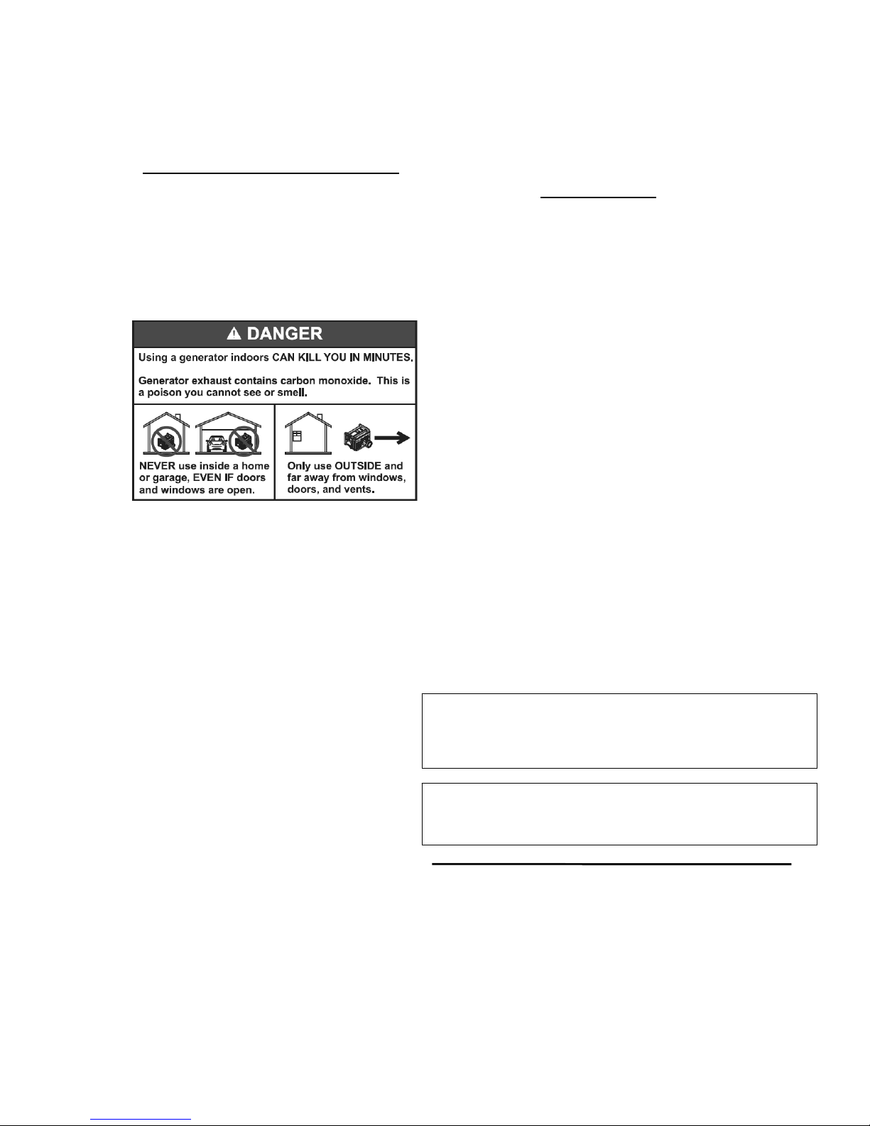
EXHAUST & LOCATION HAZARDS
• Never operate in an enclosed area or
indoors! NEVER use in the home, or
in partly enclosed areas such as
garages, even if doors and windows
are open! ONLY use outdoors and far
from open windows, doors, vents,
and in an area that will not
accumulate deadly exhaust.
• The engine exhaust fumes co nta in
carbon monoxide, which you cannot see
or smell. This poisonous gas, if breathed
in sufficient concentrations, can cause
unconsciousness or even death.
• Adequate, unobstructed flow of cooling
and ventilating air is critical to correct
generator operation. Do not alter the
installation or permit even partial
blockage of ventilation provisions, as
this can seriously affect safe operation
of the generator. The generator MUST
be operated outdoors.
• This exhaust system must be properly
maintained. Do nothing that might
render the exhaust system unsafe or in
noncompliance with any local codes
and/or standards.
• The manufacturer recommends
installing a battery operated carbon
monoxide alarm indoors, according to
the manufacturers instructions.
• If you start to feel sick, dizzy, or weak
after the generator has been running,
move to fresh air IMMEDIATELY. See a
doctor, as you could have carb on
monoxide poisoning.
FIRE HAZARDS
• Gasoline is highly FLAMMABLE and
its vapors are EXPLOSIVE. Do not
permit smoking, open flames, sparks
or heat in the vicinity while handling
gasoline.
• Never add fuel while unit is running
or hot. Allow engine to cool completely
before adding fuel.
• Never fill fuel tank indoors. Comply
with all laws regulating storage and
handling of gasoline.
• Do not overfill the fuel tank. Always
allow room for fuel expansion. If tank
is over-filled, fuel can overflow onto a
hot engine and cause FIRE or an
EXPLOSION. Never store generator
with fuel in tank where gasoline vapors
might reach an open flame, spark or
pilot light (as on a furnace, water heater
or clothes dryer). FIRE or EXPLOSION
may result. Allow unit to cool entirely
before storage.
• Wipe up any fuel or oil spills
immediately. Ensure that no
combustible materials are left on or near
the generator. Keep the area
surrounding the generator clean and
free from debris and keep a clearance of
five (5) feet on all sides to allow for
proper ventilation of the generator.
• Do not insert objects through unit’s
cooling slots.
FUELING THE GENERATOR
Use care when fueling the generator. Only fill
the fuel tank when the generator has cooled
entirely. Use fresh unleaded gasoline with a
minimum Research Octane Number (RON) of
87.
CALIFORNIA PROPOSITION 65 WARNING
Engine exhaust and some of its constituents are known to the
State of California to cause cancer, birth defects and other
CALIFORNIA PROPOSITION 65 WARNING
This product contains or emits chemicals known to the State of
California to cause cancer
,
birth defects and other reproductive
- 4- - 5-
Page 5

NOTE:
Do not use any gasoline containing more
than 10% Ethanol. NEVER fill the fuel tank
with E85 or a mixture of oil and gasoline
designated for two-cycle engines.
Do not light a cigarette or smoke
when filling the fuel tank.
Gasoline is highly FLAMMABLE
and its vapors are EXPLOSIVE. Do
not permit smoking, open flames,
sparks or heat in the vicinity while
handling gasoline.
Never fill fuel tank indoors. Never
fill fuel tank when engine is
running or hot. Avoid spilling
gasoline on a hot engine. Allow
engine to cool entirely before filling
fuel tank.
Do not overfill the fuel tank.
Always allow room for fuel
expansion. If tank is over-filled,
fuel can overflow onto a hot engine
and cause FIRE or an EXPLOSION.
Wipe up fuel spills immediately!
- 6-
Page 6

(IX) SCHEMATIC
ENGINE BLOCK
GRAY
RED
YELLOW
GREEN
BLACK
ENG.SW.
CONTROL BOX BLOCK
SPARK PLUG
YELLOW/GREEN
RED/WHITE
EARTH TERMINAL
AC SOCKET
CIRCUIT
PROTECT
20A
/125V AC
FIELD WINDING
CAPACITY WINDING
MAIN WINDING
CAPACITY
+
-
'&
Rectifier
CIRCUIT
PROTECT
DC WINDING
-22-
(I) SAFETY INFORMATION
z NEVER operate this power generator indoors or
anywhere airflow is restricted.
z To prevent fire or carbon monoxide poisoning,
NEVER
point the generator’s exhaust towards combustible
materials or in the direction of open windows or doors.
z
NEVER refuel the engine while it is running; stop the
engine before refueling.
z To prevent fire, clean any spilled fuel before starting
generator
.
z
NEVER use this power generator near open flames.
z
NEVER operate power generator on wet surfaces, rain
or snow.
z To prevent electric shock, keep everyone away from
the power generator while it is running.
z To prevent electric shock,
NEVER touch the generator
with wet hands.
- 7-
Page 7

(II) PRE-OPERATION PREPARATION
NOTE: The following checks should be
made each time the generator is used.
z To prevent electric shock,
ALWAYS ground the generator
before starting, see Picture 1.
z Use a gasoline-oil mixture. If
not, the engine may overheat.
Gasoline and oil should be mixed at
40:1 ratio. See Picture 2.
z Do not overfill the fuel tank, always
fill to the top of fuel filter. See Picture 3.
z Use the following guide to make
fuel mixture:
1. Use the fuel cap to measure oil
See Picture 4.
2. Mix gasoline and oil in separate
Container( use clean, fresh regular
Fuel-Oil˄
1 Gal gal/3.2 oz.2-stroken
Engine oil
˅
3. After shaking, pour fuel mixture
into tank.
Note˖ALWAYS use clean oil.
- 8-
FIG. J GENERATOR
PAR T
DESCRIPTION Q'TY SPEC
1 Tapping screw 4
ST4.2h13
2 Voltmeter 1
91L4
3 DC outlet 1 V type
4 Control panel 1
5 Circuit breaker (DC) 1 8A
6 Indicator 1 125VAC
7 Circuit break (AC) 1 8A
8 Plastic housing 1
9 Capacitor 1
10 Engine switch 1
11 Filter cover 1
12 Tapping screw 4
M5h16
13 Screw 1
M4h10
14 AC outlet 1 20A/125VAC
-21-
Picture 1
Picture 2
Picture 3
Picture 4
Page 8

-20-
(III) STARTING THE ENGINE
z
DO NOT plug any device into
the power generator before starting
the engine, see Picture 5.
1. Shake fuel tank before starting
the engine.
2. Turn the fuel petcock to "ON" position.
See Picture 6.
3.
Turn the choke lever to Position 1.
See Picture 7.
-9-
Picture 5
Picture 6
Picture 7
FIG. J
Page 9

4. Turn the engine switch to the
"ON" position. See Picture 8.
5. Pull slowly on the recoil starter until it is engaged, then pull
it briskly. See Picture 9.
6. Allow the generator ‘s engine to
warm up.
7. Now, turn the choke lever back to
its rightmost position, see Picture 10.
-10-
FIG. I GENERATOR
PART DESCRIPTION Q'TY SPEC
1 Stator Assy 1
2 Rotor Assy 1
3 Diode Tray 2
4 Bearing 1 6203
5 Flange Bolt 1
M8h155
6 Rear Cover 1
7 Flange Bolt 3
M6h85
8 Rectifier Stand 1
9 Rectifier 1 3510
10 Washer 1
¶5
11 Spring Washer 1
¶5
12 Bolt 1
M5h20
13 Flange Bolt 1
M6h10
14 Fan blade
1
Picture 8
Picture 9
Picture 10
-19-
Page 10

(VIII) EXPLODED VIEW-MAIN UNIT
-18-
(IV) CONNECTION
1.To prevent the power cord of the
apparatus from inadvertently becoming
unplugged, wind the power cord 2 or 3
turns around the handle of the generator.
See Picture 11.
2.Plug the power cord into the AC
receptacle. See Picture 12
3.Press this button to reset the
overload protector in order to reduce
the output load if the AC protector turns
off. See Picture 13
“1” ON
“2” OFF
-11-
Picture 11
Picture 12
Picture 13
FIG.1
Page 11

(V) STOPPING THE ENGINE
1. Before stopping engine, turn off electrical device being
powered and unplug it from
the generator. See Picture
14.
2. Turn the engine switch to “STOP”, see Picture 15.
3. Turn the fuel petcock to “OFF”, see
picture 16.
-12-
z Generator Troubleshooting
Problem Possible Cause Corrective Action
Indicator light ON
No AC output
Tripped circuit breaker Reset
Poor connection or faulty
lead
Check and repair
Broken receptacle Check and repair
Faulty circuit breaker Check and repair
Indicator light OFF
No AC output
Generator problem Check and repair
Indicator light OFF
No DC out put
Tripped circuit breaker Reset
Poor connection or faulty
DC power cord
Check and repair
Generator problem Consult dealer
Output power
available
abnormality exists
Engine RPM set too high
or low
No load for 60HZ
Set 3780rpm
Loose component Locate and tighten
Internal generator
problem
Consult dealer
DC APPLICATION: The DC terminals of the generator
may be used for charging 12-volt automotive batteries only.
Connect the charging cables to the
terminals of the generator as shown.
Be sure to observe the correct polarity!
(Picture 16)
-17-
Page 12

(VII) TROUBLESHOOTING
z Engine Troubleshooting
(VI) PERIODIC MAINTENANCE
z SPARK PLUG (Once per month)
1.Remove the spark plug, see
Picture 17.
2.Remove carbon deposits, see Picture
18.
3.Check for discoloration.
Normally, the spark plug tip should be
tan in color.
4.Check spark plug gap. It should be set
between 0.028” and 0.031” or between
0.7 and 0.8mm.
Problem Possible Cause
Corrective
Action
Engine
won’t start
Low
engine
output
Engine run
erratically
Insufficient
compression
Loose spark plug
Tighten plug
properly
Loose cylinder head bolt
Tighten bolt
properly
Damaged gasket Replace gasket
Sufficient
compression
No fuel
supplied to
combustion
chamber
Insufficient pulling
speed for starting rope
Pull rope sharply
Foreign matter in fuel
tank
Clean tank
Clogged fuel line
Clean fuel line with
dealer’s advice
No fuel in tank Supply fuel
Fuel shutoff not open
Open valve
Combustion
chamber
supplied with
fuel
Improper
spark
Spark plug
dirty with
carbon or
wet with fuel
Remove carbon or
wipe up spark plug
Damaged
spark plug
Replace spark plug
Faulty
magneto
Consult dealer
Improper
spark
Improper
adjustment
of carburetor
Consult dealer
Insufficient
pulling speed
for starting
rope
Pull rope sharply
Improper grade of fuel used Check fuel
Overloading
Check the working
condition
-16-
-13-
Page 13

z AIR FILTER (Once per month)
1. Remove air filter.
(See Picture 20 ķ
2. Wash air filter in solvent.
(See Picture 20 ĸ)
3.Coat filter with motor oil.
(See Picture 20 Ĺ)
4.Gently, squeeze motor
oil out.
(See Picture 20 ĺ
CAUTION:
ƷThe engine should never be operated without the air filter
element.
z
FUEL FILTER (Once every three months)
1. Stop the engine. 1. Clean in solvent.
2. Turn fuel petcock to “OFF”. 2. Wipe off.
3. Clean with solvent. 3. Insert into fuel tank.
See Picture 21. See Picture 22.
Picture 21 Picture 22
Picture 20
-15-
-14-
 Loading...