

Page 1
TECHNICAL GUIDE
®
LX
SERIES
FOR INSTALLATION IN ALL US REGIONS AND CANADA
SPLIT SYSTEM
HEAT PUMPS
Installation Allowed
16 SEER – R-410A – 1 PHASE
2 THRU 5 NOMINAL TONS
MODELS: CH1624 THRU 60
®
Due to continuous product improvement, specifications
are subject to change without notice.
Visit us on the web at
www.upgnet.com and www.colemanac.com
Additional rating information can be found at
www.ahridirectory.org
WARRANTY SUMMARY*
Standard 5-year limited parts warranty.
Standard 10-year limited compressor warranty.
Extended 10-Years limited parts warranty when product is
registered online within 90 days of purchase for replacement
or closing for new home construction.
*Does not apply to R-22 models, 3-Phase models, or Internet sales.
See Limited Warranty certificate in User's Information Manual for details.
5547666-CTG-A-0718
DESCRIPTION
The CH16 16 SEER Modulating Heat Pumps are the newest
offering in our successful LX Family of split system heat pumps.
These units use a state of the art inverter driven compressor to
precisely meet customers comfort requirements. Using a conventional two-stage heat pump thermostat, the system will automatically modulate capacity and airflow from 50% to 100% of
nominal capacity in 10% increments to meet the comfort
requirements of the consumer, maximizing comfort while minimizing energy bills. Designed to work with Coleman variable
speed or standard ECM indoor air handling equipment it provides consumers and dealers system installation options.
Should the unit ever require service the main control and
inverter control both provide system self-diagnostics.
FEATURES
• Improved Temperature Control - The inverter driven compressor and modulating system will automatically adjust
capacity, in heat or cool mode, to precisely match the comfort
demands of the space providing closer temperature and
humidity control.
• Easier Installation - Time is reduced by being factory
charged for a 15-Ft line set and having a factory installed filter-drier. This means less time spent brazing and charging
the system. The small base dimension and reduced unit
clearances requirements provide more retrofit applications.
• Accessible Information - QR code on unit provides quick
access to technical documents and warranty information at
www.upgnet.com.
• Durable Finish - The automotive grade champagne colored
powder painted and the specially coated wire grill and fasteners add to the corrosion resistant nature of the product allowing it to retain its aesthetics appeal throughout its life.
• Rugged Coil Protection - Coils are protected from mechanical damage by a stamped steel extruded louver coil guard
design.
• Quality Coils - Enhanced aluminum fins are mechanically
bonded to copper tubing.
• Protected Compressor - Compressors are protected by the
system high and low pressure switches. The liquid line filterdrier is factory installed to protect the system against moisture and contaminates.
• Reliable Operation - Ball bearing fan motors provide superior performance in extreme temperatures. Factory installed
accumulator protects the compressor while operating across
a wide range of conditions.
• Environmentally Friendly - CFC-free R-410A refrigerant
delivers environmentally friendly performance with zero
ozone depletion.
• Top Discharge - Warm air is blown up, away from the structure and any landscaping and allows compact location on
multi-unit applications.
• Low Operating Sound Levels - The sturdy cabinet and top
design provides sound performance as low as 76 dBA.
• Better Service Access - Diagonal base valves with open
access for Schrader removal tools and low-loss fittings and
single panel access to the electrical controls. Full corner
access using the swing out electrical box, and removable fan
guard allow easy access for unit service or maintenance.
• Agency Listed - Safety certified by CSA to UL 1995 / CSA
22.2. Performance certified to ANSI/AHRI Standard 210/240
in accordance with the Unitary Small Equipment certification
program.
FOR DISTRIBUTION USE ONLY - NOT TO BE USED AT POINT OF RETAIL SALE
Page 2
5547666-CTG-A-0718
LIST OF SECTIONS
DESCRIPTION . . . . . . . . . . . . . . . . . . . . . . . . . . . . . . . . . . . . . . . . . . 1
FEATURES . . . . . . . . . . . . . . . . . . . . . . . . . . . . . . . . . . . . . . . . . . . . 1
NOMENCLATURE . . . . . . . . . . . . . . . . . . . . . . . . . . . . . . . . . . . . . . . 2
PHYSICAL AND ELECTRICAL DATA . . . . . . . . . . . . . . . . . . . . . . . 3
DIMENSIONS . . . . . . . . . . . . . . . . . . . . . . . . . . . . . . . . . . . . . . . . . . . 3
SYSTEM CHARGE FOR VARIOUS MATCHED SYSTEMS . . . . . . . 4
LIMITATIONS . . . . . . . . . . . . . . . . . . . . . . . . . . . . . . . . . . . . . . . . . . 5
SYSTEM CAPACITY - Single Piece and Modular Air Handlers . . 6
SYSTEM CAPACITY - With High Efficiency Motor Furnaces . . .10
APPLICATION & ACCESSORIES . . . . . . . . . . . . . . . . . . . . . . . . . 53
SOUND POWER RATINGS - COOLING . . . . . . . . . . . . . . . . . . . . . 53
SOUND POWER RATINGS - HEATING . . . . . . . . . . . . . . . . . . . . . 53
UNIT OPERATION . . . . . . . . . . . . . . . . . . . . . . . . . . . . . . . . . . . . . . 54
MECHANICAL SPECIFICATIONS . . . . . . . . . . . . . . . . . . . . . . . . . 54
TYPICAL INSTALLATION . . . . . . . . . . . . . . . . . . . . . . . . . . . . . . . . 55
TYPICAL FIELD WIRING . . . . . . . . . . . . . . . . . . . . . . . . . . . . . . . . 56
ALTERNATIVE INSTALLATION CLEARANCES . . . . . . . . . . . . . . 56
PERFORMANCE DATA - 2 TON . . . . . . . . . . . . . . . . . . . . . . . . . . 57
PERFORMANCE DATA - 3 TON . . . . . . . . . . . . . . . . . . . . . . . . . . 68
PERFORMANCE DATA - 4 TON . . . . . . . . . . . . . . . . . . . . . . . . . . 83
PERFORMANCE DATA - 5 TON . . . . . . . . . . . . . . . . . . . . . . . . . 100
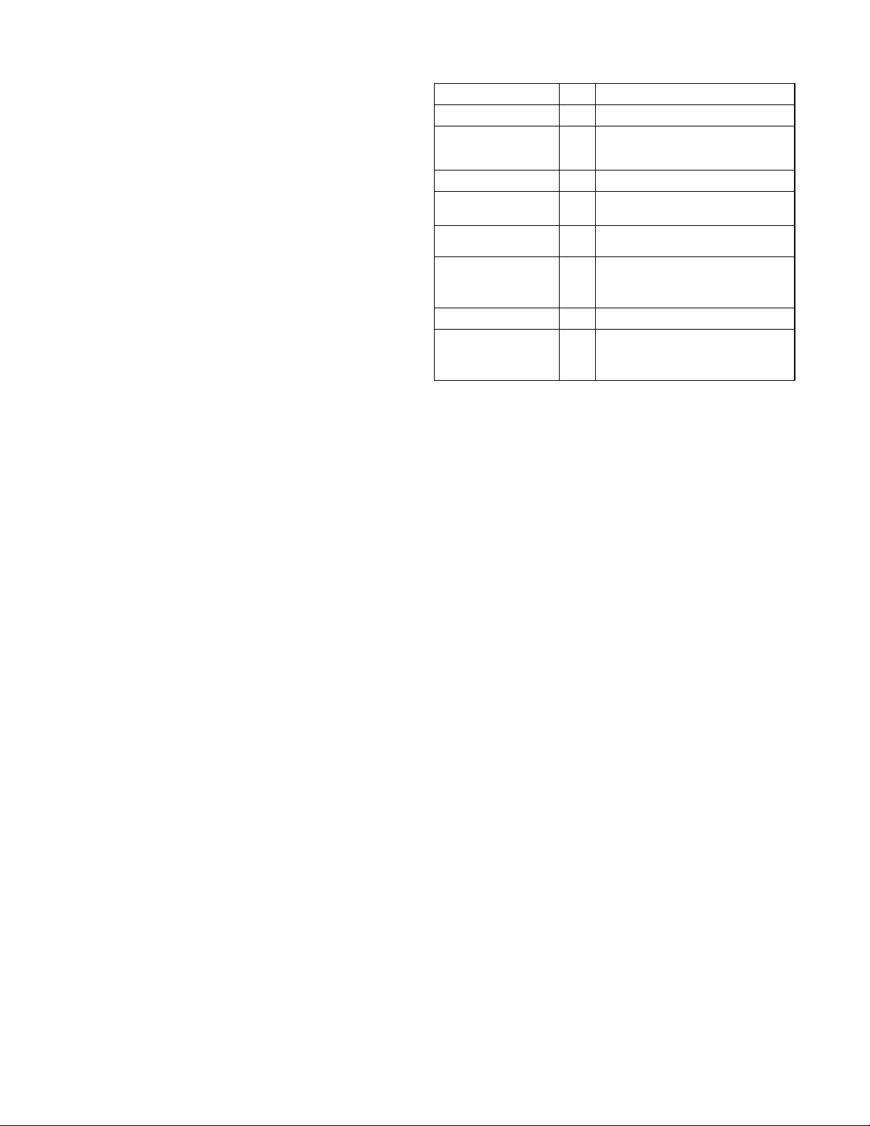
NOMENCLATURE
BRAND
PRODUCT TYPE
NOMINAL
SERIES EFFICIENCY
AND STAGING
REFRIGERANT
NOMINAL UNIT
CAPACITY (MBH)
VOLTAGE
(Voltage-Phase-Hertz)
GENERATION
(MAJOR REVISION)
FACTORY OPTION
STYLE LETTER
(Minor Revision)
Not Used for Ordering
C
C = Coleman
H
H = Heat Pump
16
16 = 16 SEER / Modulating
B
B = R-410A
24 = 2 Ton 48 = 4 Ton
36
36 = 3 Ton 60 = 5 Ton
2
2 = 208/230-1-60
1 = 1st Gen
1
2 = 2nd Gen
etc
S
S = Standard (No Options)
A = Style A
A
B = Style B
etc
2 Johnson Controls Unitary Products
Page 3
5547666-CTG-A-0718
PHYSICAL AND ELECTRICAL DATA
MODEL CH16B2421S CH16B3621S CH16B4821S CH16B6021S
Unit Supply Voltage 208-230V, 1 60Hz
Normal Voltage Range
1
Minimum Circuit Ampacity 17.2 21.0 35.6 34.7
Max. Overcurrent Device Amps
Min. Overcurrent Device Amps
2
3
30.0 35.0 60.0 60.0
20.0 25.0 40.0 50.0
Type Rotary Rotary Rotary Rotary
Compressor
Rated Load 13.19 15.20 23.73 27.42
Locked Rotor 26.0 38.0 44.5 64.5
Crankcase Heater Yes Yes Yes Yes
HS Kit Required with TXV
N/A N/A N/A N/A
Fan Diameter Inches 22 22 24 24
Rated HP 1/8 1/4 1/3 1/3
Fan Motor
Rated Load Amps 1.0 1.0 1.3 1.3
Nominal RPM 970 850 1000 1000
Nominal CFM 2850 3715 4000 4100
Face Area Sq. Ft. 16.15 19.75 23.82 23.82
Coil
Rows Deep 1112
Fins / Inch 22 18 22 18
Liquid Line Set OD (Field Installed) 3/8 3/8 3/8 3/8
Vapor Line Set OD (Field Installed)
Unit Charge (Lbs. - Oz.)
5
4
3/4 3/4 7/8
5 - 9 7 - 2 8 - 6 14 - 14
Charge Per Foot, Oz. 0.62 0.62 0.67 0.75
Operating Weight Lbs. 166 204 214 239
1. Rated in accordance with AHRI Standard 110-2012, utilization range “A”.
2. Dual element fuses or HACR circuit breaker. Maximum allowable overcurrent protection.
3. Dual element fuses or HACR circuit breaker. Minimum recommended overcurrent protection.
4. For applications with non-standard vapor line sizes, see the “Applications & Accessories” section of this Technical Guide.
5. The Unit Charge is correct for the outdoor unit, smallest matched indoor unit, and 15 feet of refrigerant tubing. For tubing lengths other than 15 feet, add or subtract the amount of refrigerant, using the difference in actual lineset length (not the equivalent length) multiplied by the per foot value.
187 to 252
1-1/8
‡
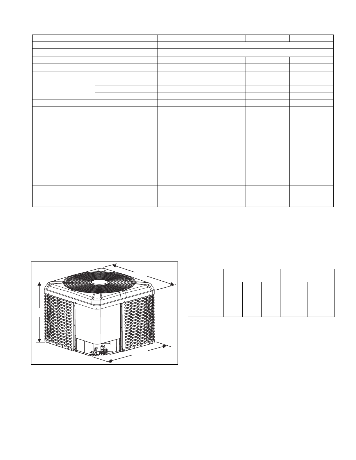
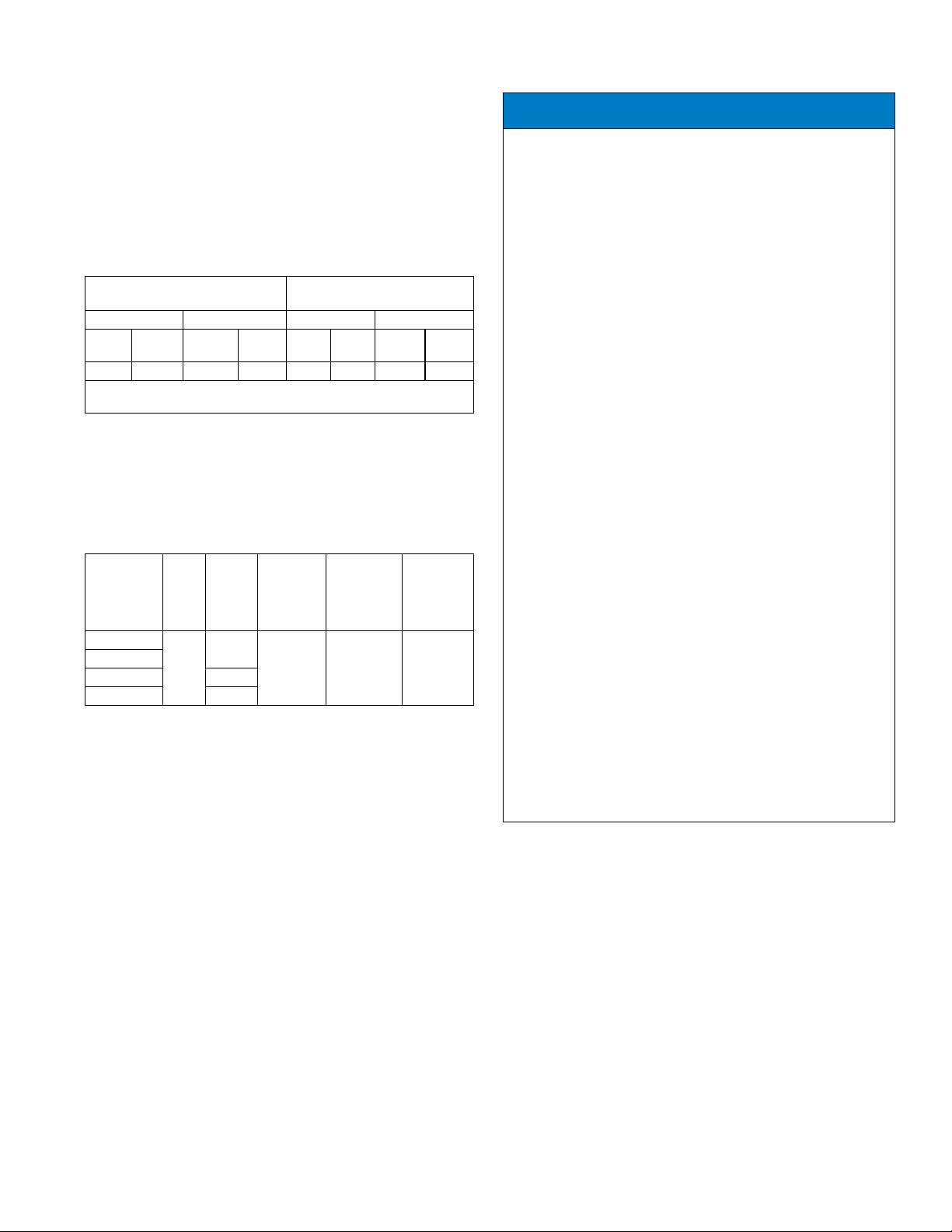
DIMENSIONS
C
Unit
Model
Dimensions
(Inches)
A B C Liquid Vapor
CH16B2421S 33-1/4 29-1/4 29-1/4
CH16B3621S 39-1/2 29-1/4 29-1/4
CH16B4821S 39-1/2 35-1/4 31-3/4 7/8
A
B
A0339-001
CH16B6021S 39-1/2 35-1/4 31-3/4 1-1/8‡
‡ Adapter fitting must be field installed for the required 1-1/8” line set.
All dimensions are in inches and are subject to change without notice.
Overall height is from bottom of base pan to top of fan guard.
Overall length and width include screw heads.
Refrigerant Connection
Service Valve Size
3/4
3/8
Johnson Controls Unitary Products 3
Page 4
5547666-CTG-A-0718
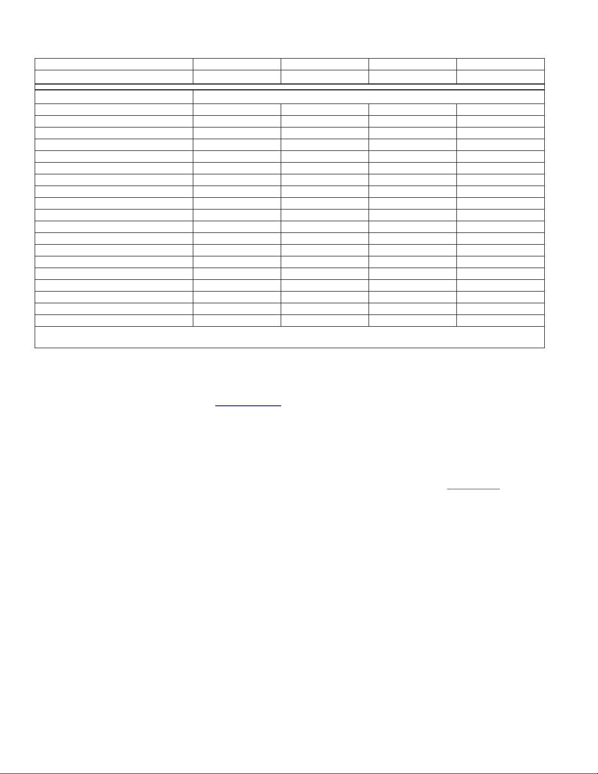
SYSTEM CHARGE FOR VARIOUS MATCHED SYSTEMS
Outdoor Unit CH16B2421S CH16B3621S CH16B4821S CH16B6021S
Required TXV
Indoor Unit
1,2
3,4
AE24B 0–––
AE30B 4–––
AE36B –0––
AE48C ––0–
AE60D –––0
AVC24B 0–––
AVC30B 4–––
AVC36(B,C) 60––
AVC42C –8––
AVC48(C,D) –80–
AVC60C ––8–
AVC60D ––90
CF/CM/CU24(A,B) 0–––
CF/CM/CU30(A,B,C) 4–––
CF/CM/CU36(A,B,C) 60––
CF/CM/CU42(B,C,D) –8––
CF/CM/CU48(C,D) –80–
CF/CM/CU60(C,D) ––8–
CF/CM64D ––90
Some of the combinations shown in the above System Charge table require Advanced Main Air Circulating Fan indoor product. For approved coil
only matches, please see the “COOLING CAPACITY - Upflow, Downflow & Horizontal Furnaces and Coils” table.
FOOTNOTES:
1. For applications requiring a TXV, use S1-1TVM*** series kit.
2. A TXV kit must be used with these indoor units to obtain system performance.
3. CF coils cannot be used in horizontal applications.
4. Charge adders shown above do not indicate that coils are rated for every application. Refer to Performance Data Tables for actual performance for specified
system matches. Obtain certified system ratings from
CHARGING PROCEDURES:
1. Check the Factory Unit Charge listed on the unit data plate to verify the refrigerant charge for the outdoor unit, the smallest matched indoor unit, and the 15 feet of
interconnecting lineset.
2. Verify the indoor metering device and additional charge required for the specific matched indoor unit in the system using the above table.
3. Make sure the unit is locked into high speed and the system stabilizes before charging. Return the heat pump main control jumper to normal when charging is complete. Add additional charge for the amount of interconnecting lineset greater than 15 feet at the rate specified in the Physical and Electrical Data Table.
4. For installations requiring additional charge, weigh in refrigerant for the specific matching indoor unit and actual lineset length.
5. Once the charge adders for matched indoor unit and for lineset have been weighed in, verify the system operation against the temperatures and pressures in the
Charging Chart for the outdoor unit. Locate Charging Charts on the outdoor unit and also in the Service Data Application Guide on
Subcool or the Superheat charging procedure in the Installation Manual according to the type of indoor metering device in the system, and allow ten minutes after
each charge adjustment for the system operation to stabilize. Record the charge adjustment made to match the Charging Chart.
6. Permanently stamp the unit data plate with the TOTAL SYSTEM CHARGE defined as follows: TOTAL SYSTEM CHARGE = Base Charge (as shipped) + charge
adder for matched indoor unit (+ or -) charge adder for actual lineset length + charge adjustments to match the Charging Chart.
BA1 BC1 BC1 BG1
Additional Charge, oz
www.ahridirectory.org.
www.upgnet.com. Follow the
4 Johnson Controls Unitary Products
Page 5
5547666-CTG-A-0718
LIMITATIONS
The unit should be installed in accordance with all National, State and
Local Safety Codes and the limitations listed below:
1. Limitations for the indoor unit, coil, and appropriate accessories
must also be observed.
2. The outdoor unit must not be installed with any duct work in the air
stream. The outdoor fan is the propeller type and is not designed
to operate against any additional external static pressure.
3. The maximum and minimum conditions for operation must be
observed to ensure a system that will give maximum performance
with minimal service.
Minimum / Maximum Operating Limit Conditions
AIR TEMPERATURE AT
OUTDOOR COIL, ° F (° C)
Min. Max. Min. Max.
DB
Cool
35(2)* -20(-29) 125(52)* 75(24) 57(14) 50(10) 72(22) 80(27)
DB
Heat
DB Cool
DB
Heat
*Reference the NOTICE under the “Unit Reduced Capacity Conditions”
section.
4. The maximum allowable equivalent line length for this product is
80 feet.
Standard Lineset Applications
Maximum allowable lineset varies depending on the vertical separation
between the evaporator and condenser. See Table 2 for allowable line
set lengths and sizing.
AIR TEMPERATURE AT
INDOOR COIL, ° F (° C)
WB
DB
Cool
Heat
WB
Cool
DB
Heat
Allowable Vertical Linesets.
Liquid
Model
24
36
48 7/8”
60 1-1/8”
Suction
Line
3/8”
Line
3/4”
Max Line
Length Units on
Equal
Level
80 feet 25 feet 25 feet
Max Suction
Line Riser -
If OD Unit is
Above ID
Unit
Max Liquid
Line Riser -
If OD Unit
is Below ID
Unit
Unit Reduced Capacity Conditions
NOTICE
Intelligence Power Module (IPM) Temperature Protection:
If excessive (IPM) inverter temperatures are sensed, the compressor
speed / capacity is reduced every 60 seconds until an acceptable
condition is reached.
When the inverter temperature returns to an acceptable level, the
system returns to normal operation.
Over / Under Current Protection:
If a low or high Current Condition is sensed, the compressor speed /
capacity is reduced every 30 seconds until an acceptable current
level is reached.
When the system reaches an acceptable current level, the compressor and fan return to normal operating conditions.
Over / Under Voltage Protection:
If a low or high supply Voltage Condition is experienced (below 197
VAC or above 252 VAC), the compressor speed / capacity is automatically reduced every 15 seconds until an acceptable voltage level
is sensed.
When an acceptable voltage level is sensed, the system automatically returns to a normal state of operation.
High Outdoor Ambient Temperature Protection:
During high outdoor ambient temperature conditions above 109°F
(43°C), the compressor speed reduces to protect the system. If the
outdoor ambient temperature goes above 125 °F (52°C), the system
goes into a soft-lockout condition halting operation for system protection. Consider these limitations when installing any of the heat pumps
included in this document.
When the system reaches acceptable operating conditions, the system returns to normal operation.
High Altitude Protection:
If the unit is installed in Altitudes of 6,500 ft / 2,000 m above sea level
or higher, the compressor and outdoor fan reduce speeds to protect
the system. It is not recommended these units be installed at altitudes
greater than 6,500 ft / 2,000 m above sea level.
Low Ambient Protection:
Cooling mode: The unit automatically adjusts to maintain cooling
operation in outdoor ambient conditions down to 35° F (2° C). The
unit reduces capacity and or cycles off if asked to provide cooling
when the outdoor temperature is at or below these conditions.
Heating Mode: The unit provides compressor heat down to an outdoor ambient temperature of -20° F (-29° C). As the outdoor ambient
temperature reduces, available heat reduces for all air source heat
pumps. Make sure the balance point and auxiliary heat are appropriately set and sized for the application of the heat pump.
Johnson Controls Unitary Products 5
Page 6
5547666-CTG-A-0718
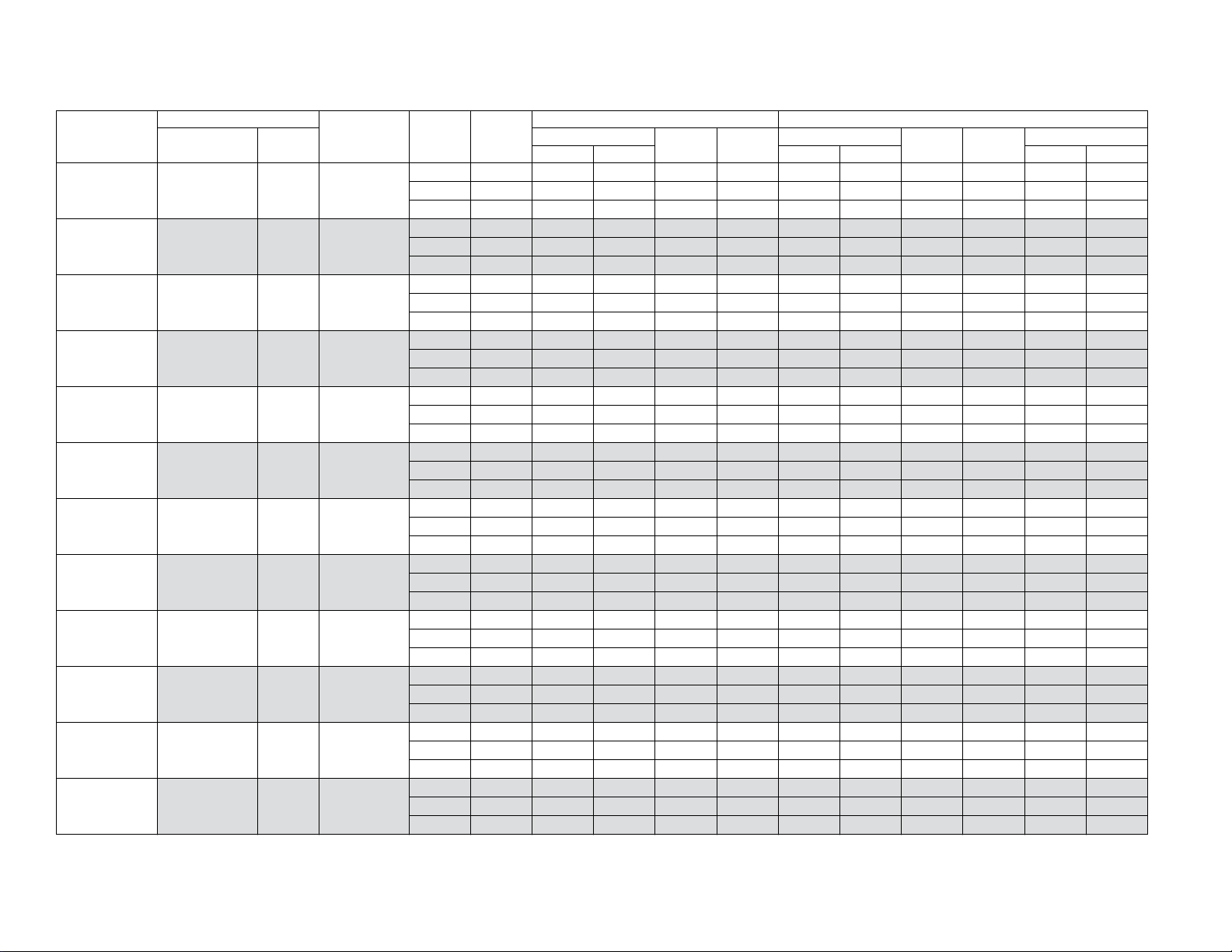
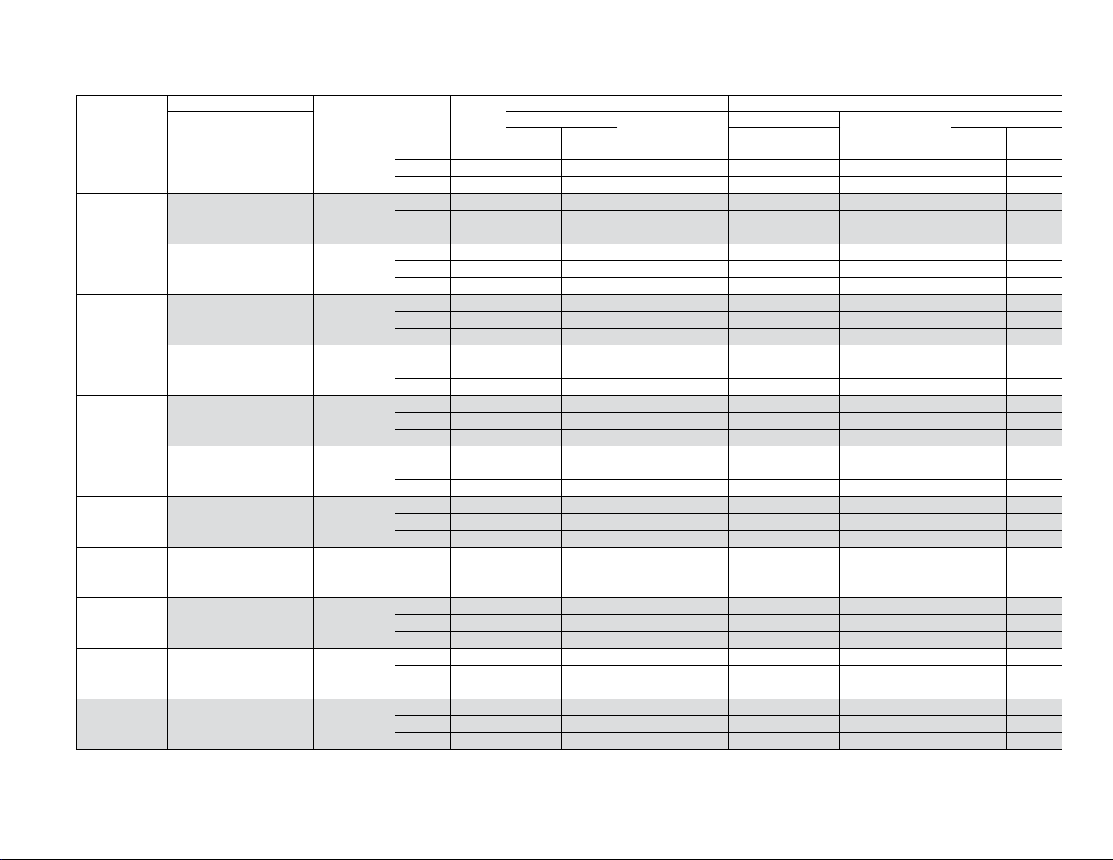
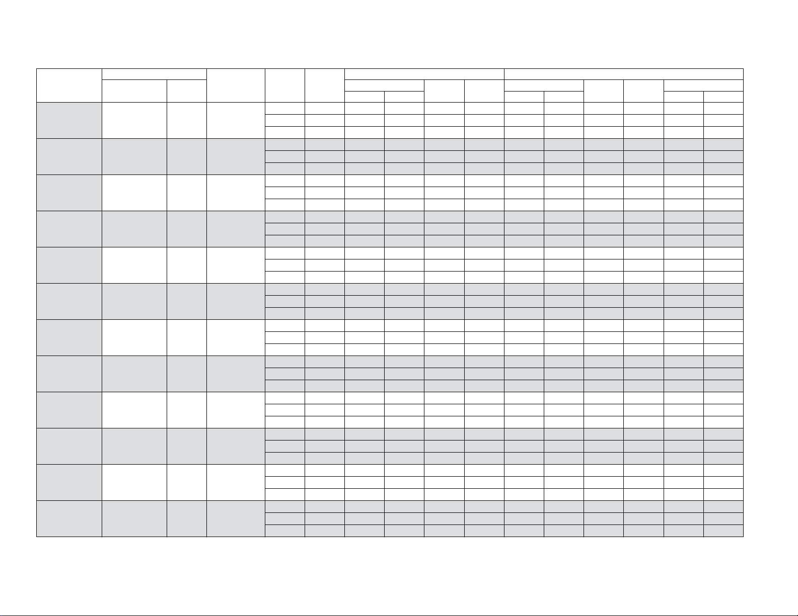
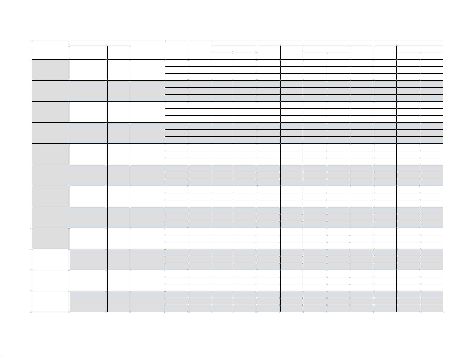
SYSTEM CAPACITY - Single Piece and Modular Air Handlers
UNIT
MODEL
CH16B2421S AE24BBA21 17.5 –
CH16B2421S
CH16B2421S AE30BX21 17.5 –
CH16B2421S AVC24BX21 17.5 –
CH16B2421S AVC30BX21 17.5 –
CH16B2421S AVC36BX21 17.5 –
CH16B2421S AVC36CX21 21.0 –
CH16B2421S ME08BN21 17.5 CF/CM24B
CH16B2421S ME08BN21 17.5 CF/CM30B
CH16B2421S ME08BN21 17.5 CF/CM36B
CH16B2421S ME08BN21 17.5 CM24BBAA1
CH16B2421S MVC08BN21 17.5 CF/CM24B
AIR HANDLER
MODEL WIDTH
COIL
MODEL
AE24BX21 17.5 –
Stage
3
RATED
CFM
High 850 25.2 18.6 17.50 12.30 24.6 15.1 9.30 7.95 3.66 2.64
Med 500 17.8 12.2 – 16.40 – – – – – –
Low 500 15.9 11.4 – 28.60 12.1 – – – 3.92 –
High 850 25.2 18.6 17.50 12.30 24.6 15.1 9.30 7.95 3.66 2.64
Med 500 17.8 12.2 – 16.40 – – – – – –
Low 500 15.9 11.4 – 28.60 12.1 – – – 3.92 –
High 875 24.0 19.2 18.25 12.50 24.0 14.8 9.00 7.45 3.82 2.74
Med 600 18.4 14.5 – 17.45 – – – – – –
Low 600 16.3 13.8 – 31.30 11.9 – – – 4.18 –
High 800 24.0 18.6 18.00 12.25 24.0 14.8 9.00 7.50 3.64 2.64
Med 525 18.0 13.7 – 17.00 – – – – – –
Low 525 16.1 12.7 – 30.55 11.7 – – – 4.00 –
High 900 24.0 19.7 18.00 12.25 24.0 15.1 9.00 7.50 3.70 2.64
Med 525 18.1 13.8 – 17.05 – – – – – –
Low 525 16.1 12.7 – 30.75 11.7 – – – 4.00 –
High 900 24.0 19.7 17.75 12.00 24.0 15.0 9.00 7.45 3.70 2.64
Med 625 18.5 14.8 – 17.05 – – – – – –
Low 625 16.3 14.0 – 29.85 12.0 – – – 4.10 –
High 700 24.0 17.7 17.75 12.25 24.0 14.6 9.00 7.55 3.56 2.64
Med 475 17.6 12.9 – 16.55 – – – – – –
Low 475 15.9 12.2 – 29.45 11.6 – – – 3.86 –
High 925 24.6 19.9 18.25 12.50 24.0 15.0 9.00 7.40 3.82 2.72
Med 650 18.7 15.1 – 17.45 – – – – – –
Low 650 16.4 14.4 – 30.65 12.0 – – – 4.20 –
High 950 25.4 21.2 18.00 12.25 24.2 15.1 9.00 7.45 3.80 2.68
Med 650 18.6 15.2 – 17.25 – – – – – –
Low 650 16.3 14.3 – 30.20 12.1 – – – 4.18 –
High 875 24.0 19.3 18.00 12.25 24.0 15.0 9.00 7.45 3.74 2.68
Med 625 18.5 15.0 – 17.20 – – – – – –
Low 625 16.3 14.0 – 30.10 12.0 – – – 4.14 –
High 925 24.6 19.9 18.25 12.50 24.0 15.0 9.00 7.40 3.82 2.72
Med 650 18.7 15.1 – 17.45 – – – – – –
Low 650 16.4 14.4 – 30.65 12.0 – – – 4.20 –
High 875 24.0 19.2 17.75 12.25 24.0 15.0 9.00 7.45 3.70 2.66
Med 625 18.5 14.8 – 17.15 – – – – – –
Low 625 16.4 14.1 – 30.10 12.0 – – – 4.12 –
COOLING
NET MBH
TOTAL SENS. 47°F OD 17°F OD 47°F OD 17°F OD
1
SEER EER
NET MBH
HEATING
HSPF IV HSPF V
2
COP
6 Johnson Controls Unitary Products
Page 7
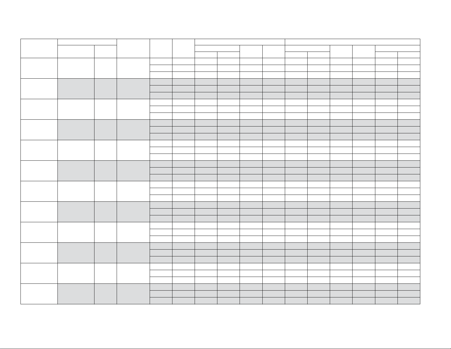
SYSTEM CAPACITY - Single Piece and Modular Air Handlers (Continued)
UNIT
MODEL
CH16B2421S MVC08BN21 17.5 CF/CM30B
CH16B2421S MVC08BN21 17.5 CF/CM36B
CH16B2421S MVC08BN21 17.5 CF24BBAA1
CH16B2421S MVC12BN21 17.5 CF/CM24B
CH16B2421S MVC12BN21 17.5 CF/CM30B
CH16B2421S MVC12BN21 17.5 CF/CM36B
CH16B2421S MVC12BN21 17.5 CF24BBAA1
CH16B2421S MVC14DN21 24.5 CF/CM30D
CH16B2421S MVC14DN21 24.5 CF/CM36D
CH16B2421S MVC16CN21 21.0 CF/CM30C
CH16B2421S MVC16CN21 21.0 CF/CM36C
CH16B3621S AE36BX21 17.5 –
AIR HANDLER
MODEL WIDTH
COIL
MODEL
Stage
3
RATED
CFM
NET MBH
TOTAL SENS. 47°F OD 17°F OD 47°F OD 17°F OD
High 825 24.0 19.1 17.25 11.75 24.0 15.1 9.00 7.45 3.58 2.60
Med 550 18.1 13.8 – 16.55 – – – – – –
Low 550 16.1 13.0 – 28.70 11.9 – – – 3.94 –
High 850 24.0 19.2 17.25 12.00 24.0 15.0 9.00 7.45 3.64 2.62
Med 600 18.3 14.4 – 16.75 – – – – – –
Low 600 16.2 13.5 – 29.05 12.0 – – – 4.02 –
High 875 24.0 19.2 17.75 12.25 24.0 15.0 9.00 7.45 3.70 2.66
Med 625 18.5 14.8 – 17.15 – – – – – –
Low 625 16.4 14.1 – 30.10 12.0 – – – 4.12 –
High 800 24.0 18.6 17.50 12.00 24.0 14.9 9.00 7.45 3.60 2.62
Med 550 18.1 13.8 – 16.65 – – – – – –
Low 550 16.1 13.0 – 29.10 11.9 – – – 3.96 –
High 875 24.0 19.2 17.00 11.75 24.0 15.3 9.00 7.45 3.58 2.56
Med 650 18.4 15.0 – 16.45 – – – – – –
Low 650 16.3 14.3 – 27.85 12.2 – – – 4.00 –
High 925 24.6 20.0 16.75 10.75 24.6 15.9 8.75 7.20 3.44 2.46
Med 550 18.0 13.8 – 16.10 – – – – – –
Low 550 16.0 12.9 – 27.40 12.0 – – – 3.84 –
High 800 24.0 18.6 17.50 12.00 24.0 14.9 9.00 7.45 3.60 2.62
Med 550 18.1 13.8 – 16.65 – – – – – –
Low 550 16.1 13.0 – 29.10 11.9 – – – 3.96 –
High 950 25.2 21.0 16.25 10.50 25.4 16.1 8.75 7.25 3.38 2.40
Med 550 18.0 13.8 – 16.10 – – – – – –
Low 550 16.0 12.9 – 27.40 12.0 – – – 3.84 –
High 950 25.2 21.0 15.00 10.25 25.4 16.1 8.75 7.20 3.38 2.40
Med 700 18.3 15.5 – 15.25 – – – – – –
Low 700 16.1 14.7 – 24.35 12.5 – – – 3.82 –
High 725 24.0 18.0 17.25 11.75 24.0 14.8 9.00 7.50 3.52 2.60
Med 525 17.9 13.6 – 16.45 – – – – – –
Low 525 16.0 12.6 – 28.75 11.8 – – – 3.90 –
High 900 24.0 19.6 17.25 11.50 24.0 15.3 9.00 7.45 3.60 2.58
Med 625 18.4 14.7 – 16.60 – – – – – –
Low 625 16.2 13.9 – 28.40 12.1 – – – 4.00 –
High 1225 34.8 25.8 16.75 11.25 35.0 22.2 10.00 8.50 3.50 2.72
Med 850 24.6 18.4 – 15.45 – – – – – –
Low 850 22.4 17.2 – 26.90 18.1 – – – 4.12 –
COOLING
SEER EER
5547666-CTG-A-0718
1
NET MBH
HEATING
HSPF IV HSPF V
2
COP
Johnson Controls Unitary Products 7
Page 8
5547666-CTG-A-0718
SYSTEM CAPACITY - Single Piece and Modular Air Handlers (Continued)
UNIT
MODEL
CH16B3621S AE36CX21 21.0 –
CH16B3621S AVC36BX21 17.5 –
CH16B3621S AVC36CX21 21.0 –
CH16B3621S AVC42CX21 21.0 –
CH16B3621S AVC48CX21 21.0 –
CH16B3621S AVC48DX21 24.5 –
CH16B3621S ME12BN21 17.5 CF/CM36B
CH16B3621S ME12BN21 17.5 CF36BBCA1
CH16B3621S ME12BN21 17.5 CF42B
CH16B3621S ME14DN21 24.5 CF/CM36D
CH16B3621S ME14DN21 24.5 CF/CM42D
CH16B3621S ME14DN21 24.5 CF/CM48D
AIR HANDLER
MODEL WIDTH
COIL
MODEL
Stage
3
RATED
CFM
NET MBH
TOTAL SENS. 47°F OD 17°F OD 47°F OD 17°F OD
High 1275 34.8 28.8 16.50 10.50 35.2 22.6 9.50 8.00 3.54 2.66
Med 750 24.6 18.9 – 15.30 – – – – – –
Low 750 22.2 18.0 – 27.55 18.1 – – – 4.14 –
High 1000 34.0 25.6 16.75 10.75 35.0 22.2 9.50 7.70 3.42 2.70
Med 675 23.8 17.8 – 15.25 – – – – – –
Low 675 21.8 16.9 – 28.80 18.1 – – – 4.04 –
High 1175 34.8 27.8 16.75 11.00 35.0 22.2 9.75 8.00 3.56 2.72
Med 825 24.6 19.9 – 15.65 – – – – – –
Low 825 22.4 19.0 – 27.85 18.2 – – – 4.22 –
High 1325 35.4 29.8 16.75 10.75 34.8 22.6 9.75 7.95 3.62 2.70
Med 825 24.6 19.8 – 15.70 – – – – – –
Low 825 22.4 19.0 – 27.60 18.1 – – – 4.26 –
High 1275 35.2 29.2 17.00 11.00 34.8 22.4 9.75 8.20 3.66 2.74
Med 825 24.8 20.0 – 15.75 – – – – – –
Low 825 22.4 19.0 – 27.70 18.1 – – – 4.26 –
High 1225 35.0 28.4 17.25 11.25 34.6 22.2 9.75 7.90 3.68 2.78
Med 800 24.6 19.6 – 15.80 – – – – – –
Low 800 22.4 18.7 – 28.25 18.0 – – – 4.28 –
High 1050 34.0 26.2 16.25 10.75 35.0 22.2 9.50 7.75 3.46 2.70
Med 875 24.6 20.4 – 15.45 – – – – – –
Low 875 22.6 19.7 – 26.90 18.4 – – – 4.16 –
High 1050 34.0 26.2 16.25 10.75 35.0 22.2 9.50 7.75 3.46 2.70
Med 875 24.6 20.4 – 15.45 – – – – – –
Low 875 22.6 19.7 – 26.90 18.4 – – – 4.16 –
High 1050 34.4 26.2 16.25 11.00 34.8 22.2 9.75 7.95 3.52 2.72
Med 875 24.8 20.6 – 15.65 – – – – – –
Low 875 22.4 19.6 – 26.85 18.3 – – – 4.20 –
High 1000 34.0 25.6 16.50 10.75 35.0 22.2 9.00 7.60 3.42 2.70
Med 700 24.0 18.0 – 15.25 – – – – – –
Low 700 21.8 17.2 – 28.60 18.1 – – – 4.04 –
High 975 33.8 25.2 16.50 10.75 34.6 22.0 9.00 7.55 3.48 2.72
Med 675 24.2 17.9 – 15.45 – – – – – –
Low 675 21.8 16.9 – 28.90 17.9 – – – 4.10 –
High 1025 34.2 25.8 17.00 11.25 34.4 22.0 9.75 7.85 3.58 2.78
Med 900 25.0 21.0 – 16.05 – – – – – –
Low 900 22.6 20.0 – 28.05 18.2 – – – 4.34 –
COOLING
SEER EER
1
NET MBH
HEATING
HSPF IV HSPF V
2
COP
8 Johnson Controls Unitary Products
Page 9
SYSTEM CAPACITY - Single Piece and Modular Air Handlers (Continued)
UNIT
MODEL
CH16B3621S MVC12BN21 17.5 CF42B
CH16B3621S MVC14DN21 24.5 CF/CM42D
CH16B3621S MVC14DN21 24.5 CF/CM48D
CH16B3621S MVC16CN21 21.0 CF/CM36C
CH16B3621S MVC16CN21 21.0 CF/CM42C
CH16B3621S MVC16CN21 21.0 CF42CBCA1
CH16B3621S MVC20DN21 24.5 CF/CM36D
CH16B3621S MVC20DN21 24.5 CF/CM42D
CH16B3621S MVC20DN21 24.5 CF/CM48D
CH16B4821S AE48CBC21 21.0 –
CH16B4821S AE48CX21 21.0 –
CH16B4821S AE48DBC21 24.5 –
AIR HANDLER
MODEL WIDTH
COIL
MODEL
Stage
3
RATED
CFM
NET MBH
TOTAL SENS. 47°F OD 17°F OD 47°F OD 17°F OD
High 975 34.0 25.0 16.50 11.00 34.6 22.0 9.50 6.75 3.46 2.72
Med 675 24.2 17.8 – 15.55 – – – – – –
Low 675 21.8 16.9 – 28.95 18.0 – – – 4.08 –
High 1325 35.4 29.8 17.00 11.25 35.0 22.2 9.75 7.90 3.64 2.76
Med 850 25.0 20.4 – 16.15 – – – – – –
Low 850 22.6 19.4 – 28.70 17.9 – – – 4.30 –
High 1100 35.0 27.0 17.00 11.50 34.6 21.8 9.75 7.90 3.60 2.80
Med 725 24.6 18.6 – 15.55 – – – – – –
Low 725 22.0 17.6 – 30.40 17.7 – – – 4.20 –
High 1025 34.2 25.8 16.75 11.00 35.0 22.0 9.50 7.60 3.44 2.74
Med 700 24.2 18.3 – 15.50 – – – – – –
Low 700 22.0 17.4 – 29.45 17.9 – – – 4.08 –
High 1025 34.4 26.0 16.75 11.25 34.8 21.8 9.75 8.05 3.50 2.76
Med 700 24.4 18.2 – 15.60 – – – – – –
Low 700 21.8 17.2 – 29.50 17.8 – – – 4.12 –
High 1025 34.4 26.0 16.75 11.25 34.8 21.8 9.75 8.05 3.50 2.76
Med 700 24.4 18.2 – 15.60 – – – – – –
Low 700 21.8 17.2 – 29.50 17.8 – – – 4.12 –
High 1275 35.4 29.4 17.00 11.25 35.0 22.0 9.75 7.85 3.44 2.72
Med 875 24.8 20.6 – 16.00 – – – – – –
Low 875 22.6 19.7 – 28.60 18.0 – – – 4.28 –
High 1300 35.4 29.6 17.25 11.25 34.8 22.0 9.75 7.80 3.64 2.78
Med 900 25.0 21.0 – 16.25 – – – – – –
Low 900 22.6 20.0 – 28.65 18.0 – – – 4.34 –
High 1300 35.6 29.6 17.00 11.50 34.6 22.0 9.75 7.75 3.68 2.80
Med 900 25.0 21.0 – 16.20 – – – – – –
Low 900 22.8 20.2 – 28.65 17.9 – – – 4.36 –
High 1425 47.0 31.8 16.70 10.20 47.0 28.4 9.70 8.10 3.22 2.56
Med 1050 33.4 23.2 – 15.30 – – – – – –
Low 1075 28.0 21.6 – 27.00 22.2 – – – 4.20 –
High 1425 47.0 31.8 16.70 10.20 47.0 28.4 9.70 8.10 3.22 2.56
Med 1050 33.4 23.2 – 15.30 – – – – – –
Low 1075 28.0 21.6 – 27.00 22.2 – – – 4.20 –
High 1675 47.0 35.8 17.00 9.75 48.0 28.2 9.50 7.70 3.16 2.54
Med 1125 33.8 27.4 – 15.85 – – – – – –
Low 1125 28.2 24.6 – 28.60 22.2 – – – 4.36 –
COOLING
SEER EER
5547666-CTG-A-0718
1
NET MBH
HEATING
HSPF IV HSPF V
2
COP
Johnson Controls Unitary Products 9
Page 10
5547666-CTG-A-0718
SYSTEM CAPACITY - Single Piece and Modular Air Handlers (Continued)
UNIT
MODEL
CH16B4821S AE48DX21 24.5 –
CH16B4821S AVC48CX21 21.0 –
CH16B4821S AVC48DX21 24.5 –
CH16B4821S AVC60CX21 21.0 –
CH16B4821S AVC60DX21 24.5 –
CH16B4821S ME14DN21 24.5 CF/CM64D
CH16B4821S MVC14DN21 24.5 CF/CM48D
CH16B4821S MVC16CN21 21.0 CF/CM48C
CH16B4821S MVC16CN21 21.0 CF/CM60C
CH16B4821S MVC16CN21 21.0 CF48CBCA1
CH16B4821S MVC20DN21 24.5 CF/CM48D
CH16B4821S MVC20DN21 24.5 CF/CM60D
AIR HANDLER
MODEL WIDTH
COIL
MODEL
Stage
3
RATED
CFM
NET MBH
TOTAL SENS. 47°F OD 17°F OD 47°F OD 17°F OD
High 1675 47.0 35.8 17.00 9.75 48.0 28.2 9.50 7.70 3.16 2.54
Med 1125 33.8 27.4 – 15.85 – – – – – –
Low 1125 28.2 24.6 – 28.60 22.2 – – – 4.36 –
High 1275 46.5 33.4 16.50 9.75 48.0 27.6 9.25 7.55 3.12 2.54
Med 850 32.4 23.2 – 15.35 – – – – – –
Low 850 27.4 21.2 – 28.15 21.8 – – – 4.10 –
High 1425 47.5 35.4 16.75 10.00 48.0 28.2 9.50 7.80 3.28 2.62
Med 925 33.0 24.4 – 15.70 – – – – – –
Low 925 27.6 22.2 – 28.55 22.4 – – – 4.36 –
High 1275 47.0 33.6 16.25 9.75 47.5 28.2 9.25 7.55 3.16 2.56
Med 850 32.4 23.2 – 15.25 – – – – – –
Low 850 27.2 21.2 – 27.20 22.0 – – – 4.18 –
High 1400 48.0 35.6 17.00 10.00 46.5 29.4 10.00 8.35 3.40 2.76
Med 1075 34.0 26.6 – 16.10 – – – – – –
Low 1075 27.8 24.2 – 28.35 21.2 – – – 4.44 –
High 1375 48.0 35.4 17.00 10.00 46.0 29.0 10.00 8.40 3.36 2.76
Med 925 33.2 24.6 – 15.95 – – – – – –
Low 925 27.4 22.2 – 28.65 20.6 – – – 4.24 –
High 1450 48.0 36.2 16.75 10.00 47.5 28.0 9.50 7.35 3.26 2.62
Med 900 32.8 24.0 – 15.75 – – – – – –
Low 900 27.6 22.0 – 28.75 21.8 – – – 4.22 –
High 1400 47.5 35.2 16.75 10.00 47.5 28.0 9.50 7.50 3.22 2.60
Med 900 32.8 24.0 – 15.55 – – – – – –
Low 900 27.4 21.8 – 28.10 22.0 – – – 4.18 –
High 1400 48.0 35.8 16.50 10.00 47.0 28.2 9.50 7.35 3.26 2.64
Med 900 32.8 24.0 – 15.55 – – – – – –
Low 900 27.4 21.8 – 28.15 21.6 – – – 4.18 –
High 1400 47.5 35.2 16.75 10.00 47.5 28.0 9.50 7.50 3.22 2.60
Med 900 32.8 24.0 – 15.55 – – – – – –
Low 900 27.4 21.8 – 28.10 22.0 – – – 4.18 –
High 1550 46.5 34.4 17.00 9.75 48.0 27.8 9.50 7.40 3.14 2.54
Med 1025 33.4 25.6 – 15.85 – – – – – –
Low 1025 28.0 23.4 – 28.80 22.0 – – – 4.32 –
High 1375 48.0 35.4 17.00 10.25 47.0 28.2 9.50 7.50 3.30 2.66
Med 950 33.2 24.6 – 15.80 – – – – – –
Low 950 27.4 22.4 – 28.70 21.6 – – – 4.26 –
COOLING
SEER EER
1
NET MBH
HEATING
HSPF IV HSPF V
2
COP
10 Johnson Controls Unitary Products
Page 11
5547666-CTG-A-0718
SYSTEM CAPACITY - Single Piece and Modular Air Handlers (Continued)
UNIT
MODEL
AIR HANDLER
MODEL WIDTH
COIL
MODEL
Stage
3
RATED
CFM
NET MBH
TOTAL SENS. 47°F OD 17°F OD 47°F OD 17°F OD
COOLING
1
SEER EER
NET MBH
HEATING
HSPF IV HSPF V
High 1550 48.0 37.2 17.00 10.25 46.5 29.8 10.00 8.00 3.50 2.82
CH16B4821S MVC20DN21 24.5 CF/CM64D
Med 1025 33.6 25.8 – 15.95 – – – – – –
Low 1025 27.6 23.4 – 28.50 20.8 – – – 4.30 –
High 1850 56.0 39.0 16.00 9.90 59.0 33.2 9.10 7.95 3.34 2.60
CH16B6021S AE60DBG21 24.5 –
Med 1175 38.0 27.0 – 14.85 – – – – – –
Low 1150 31.2 23.8 – 25.50 25.6 – – – 4.14 –
High 1850 56.0 39.0 16.00 9.90 59.0 33.2 9.10 7.95 3.34 2.60
CH16B6021S AE60DX21 24.5 –
Med 1175 38.0 27.0 – 14.85 – – – – – –
Low 1150 31.2 23.8 – 25.50 25.6 – – – 4.14 –
High 1400 55.5 39.0 16.25 10.00 58.5 32.0 9.25 7.60 3.40 2.74
CH16B6021S AVC60DX21 24.5 –
Med 1075 36.6 27.8 – 15.00 – – – – – –
Low 1075 31.2 25.4 – 27.35 25.4 – – – 4.28 –
High 1775 57.5 44.0 16.25 10.25 58.5 32.6 9.50 7.80 3.60 2.74
CH16B6021S MVC20DN21 24.5 CF/CM64D
Med 1125 37.8 29.2 – 15.25 – – – – – –
Low 1125 31.2 26.4 – 27.10 25.2 – – – 4.28 –
Rated in accordance with DOE test procedures (Federal Register 12-27-79 and 3-18-88) and ANSI/AHRI Standard 210/240.
1. Cooling MBH based on 80°F entering air temperature, 50% RH (Relative Humidity), and rated air flow.
EER (Energy Efficiency Ratio) is the total cooling output in BTUs at 95°F outdoor ambient divided by the total electric power in watt-hours at those conditions.
SEER (Seasonal Energy Efficiency Ratio) is the total cooling output in BTUs during a normal annual usage period for cooling divided by the total electric power input in watt-hours during the same period.
2. Heating MBH based on AHRI standards of 70°F DB (Dry Bulb) entering indoor air, 72% RH (Relative Humidity) outdoor air with 25 feet of interconnecting piping and no supplemental electric heat operation.
HSPF (Heating Seasonal Performance Factor) is the total heating output during a normal annual usage period for heating divided by the total electric power input during the same period.
COP (Coefficient of Performance) equals Heating MBH output divided by (total KW input x 3.412).
— = Not applicable.
CM coils available with a factory installed horizontal drain pan. See price pages for specific model number.
2
COP
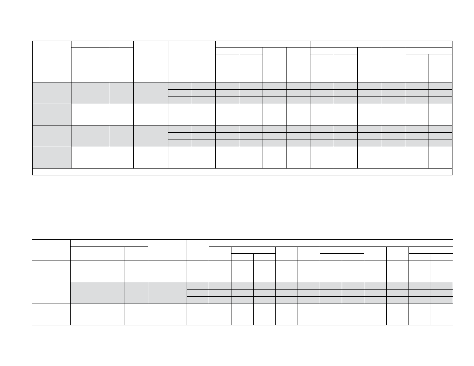
SYSTEM CAPACITY - With High Efficiency Motor Furnaces1
UNIT
MODEL
FURNACE
MODEL WIDTH
COIL
MODEL
Stage
RATED
CFM
TOTAL SENS. 47°F OD 17°F OD 47°F OD 17°F OD
High 800 24.0 18.6 17.25 11.75 24.0 15.0 9.00 7.50 3.56 2.60
CH16B2421S TM8V060A12MP12C 14.5 CF/CM24A
Med 575 18.2 14.2 – 16.60 ––––––
Low 575 16.1 13.3 – 28.55 12.0 – – – 3.96 –
High 650 24.0 17.4 16.75 11.75 24.0 14.8 8.75 7.30 3.40 2.56
CH16B2421S
TM8V060A12MP12C 14.5 CF/CM30A
Med 450 17.4 12.5 – 15.90 – – – – – –
Low 450 15.7 11.7 – 27.55 11.7 – – – 3.74 –
High 925 24.6 19.3 18.00 12.00 24.6 15.0 9.00 7.40 3.64 2.66
CH16B2421S TM8V060A12MP12C 14.5 CF/CM36A
Med 650 18.5 15.3 – 17.15 ––––––
Low 650 16.4 14.5 – 30.35 12.3 – – – 4.24 –
Johnson Controls Unitary Products 11
COOLING HEATING
NET MBH
SEER EER
NET MBH
HSPF IV HSPF V
COP
Page 12
5547666-CTG-A-0718
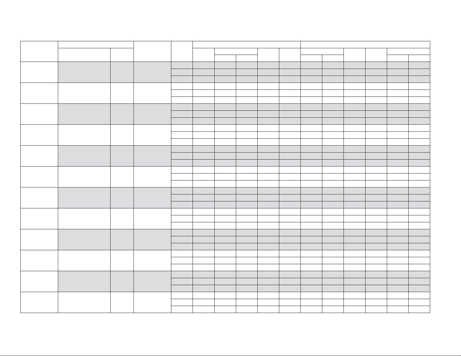
SYSTEM CAPACITY - With High Efficiency Motor Furnaces1 (Continued)
UNIT
MODEL
CH16B2421S TM8V060A12MP12C 14.5 CF24ABAA1
CH16B2421S TM8V060A12MP12C 14.5 CF30ABAA1
CH16B2421S TM8V080B12MP12C 17.5 CF/CM24B
CH16B2421S TM8V080B12MP12C 17.5 CF/CM30B
CH16B2421S TM8V080B12MP12C 17.5 CF/CM36B
CH16B2421S TM8V080B12MP12C 17.5 CF24BBAA1
CH16B2421S TM8V080C16MP12C 21.0 CF/CM24C
CH16B2421S TM8V080C16MP12C 21.0 CF/CM30C
CH16B2421S TM8V080C16MP12C 21.0 CF/CM36C
CH16B2421S TM8V100C16MP12C 21.0 CF/CM24C
CH16B2421S TM8V100C16MP12C 21.0 CF/CM30C
CH16B2421S TM8V100C16MP12C 21.0 CF/CM36C
FURNACE
MODEL WIDTH
COIL
MODEL
Stage
High 800 24.0 18.6 17.25 11.75 24.0 15.0 9.00 7.50 3.56 2.60
Med 575 18.2 14.2 – 16.60 – – – – – –
Low 575 16.1 13.3 – 28.55 12.0 – – – 3.96 –
High 650 24.0 17.4 16.75 11.75 24.0 14.8 8.75 7.30 3.40 2.56
Med 450 17.4 12.5 – 15.90 ––––––
Low 450 15.7 11.7 – 27.55 11.7 – – – 3.74 –
High 875 24.0 19.5 17.75 12.00 24.0 15.1 9.00 7.40 3.72 2.66
Med 625 18.4 15.0 – 16.85 – – – – – –
Low 625 16.4 14.2 – 29.40 12.3 – – – 4.16 –
High 775 24.0 18.4 17.75 12.00 24.0 15.0 9.00 7.45 3.64 2.66
Med 625 18.5 15.1 – 16.90 ––––––
Low 625 16.4 14.2 – 29.45 12.3 – – – 4.14 –
High 800 24.0 18.7 17.75 12.00 24.0 15.0 9.00 7.45 3.66 2.66
Low 625 16.4 14.2 – 29.55 12.3 – – – 4.16 –
High 875 24.0 19.5 17.75 12.00 24.0 15.1 9.00 7.40 3.72 2.66
Med 625 18.4 15.0 – 16.85 ––––––
Low 625 16.4 14.2 – 29.40 12.3 – – – 4.16 –
High 900 24.0 18.6 17.50 11.75 24.0 15.1 9.00 7.45 3.56 2.62
Med 500 17.9 13.4 – 16.70 – – – – – –
Low 500 16.0 12.6 – 29.65 12.1 – – – 4.00 –
High 900 24.0 18.6 17.00 11.75 24.0 15.1 9.00 7.40 3.56 2.62
Med 625 18.2 14.9 – 16.75 ––––––
Low 625 16.4 14.2 – 29.65 12.3 – – – 4.16 –
High 825 24.0 18.9 17.00 12.00 24.0 15.1 9.00 7.40 3.66 2.64
Med 700 18.7 15.4 – 16.70 – – – – – –
Low 700 16.5 14.8 – 28.45 12.5 – – – 4.14 –
High 900 24.0 18.6 17.50 11.75 24.0 15.1 9.00 7.45 3.56 2.62
Med 500 17.9 13.4 – 16.70 ––––––
Low 500 16.0 12.6 – 29.65 12.1 – – – 4.00 –
High 900 24.0 18.6 17.00 11.75 24.0 15.1 9.00 7.40 3.56 2.62
Med 625 18.2 14.9 – 16.75 – – – – – –
Low 625 16.4 14.2 – 29.65 12.3 – – – 4.16 –
High 825 24.0 18.9 17.00 12.00 24.0 15.1 9.00 7.40 3.66 2.64
Med 700 18.7 15.4 – 16.70 ––––––
Low 700 16.5 14.8 – 28.45 12.5 – – – 4.14 –
RATED
CFM
Me 625 18.5 15.0 – 16.90 – – – – – –
COOLING HEATING
NET MBH
TOTAL SENS. 47°F OD 17°F OD 47°F OD 17°F OD
SEER EER
NET MBH
HSPF IV HSPF V
COP
12 Johnson Controls Unitary Products
Page 13

SYSTEM CAPACITY - With High Efficiency Motor Furnaces1 (Continued)
UNIT
MODEL
CH16B2421S TM8X060A12MP11 14.5 CF/CM24A
CH16B2421S TM8X060A12MP11 14.5 CF/CM30A
CH16B2421S TM8X060A12MP11 14.5 CF/CM36A
CH16B2421S TM8X060A12MP11 14.5 CF24ABAA1
CH16B2421S TM8X060A12MP11 14.5 CF30ABAA1
CH16B2421S TM8X080B12MP11 17.5 CF/CM24B
CH16B2421S TM8X080B12MP11 17.5 CF/CM30B
CH16B2421S TM8X080B12MP11 17.5 CF/CM36B
CH16B2421S TM8X080B12MP11 17.5 CF24BBAA1
CH16B2421S TM8Y060A12MP11 14.5 CF/CM24A
CH16B2421S TM8Y060A12MP11 14.5 CF/CM30A
CH16B2421S TM8Y060A12MP11 14.5 CF/CM36A
FURNACE
MODEL WIDTH
COIL
MODEL
Stage
High 850 24.0 19.0 17.00 12.00 24.0 15.1 9.00 7.45 3.68 2.64
Med 600 18.4 14.5 – 16.85 – – – – – –
Low 600 16.2 13.7 – 29.10 12.0 – – – 4.04 –
High 800 24.0 18.5 17.00 12.25 24.0 14.9 9.00 7.50 3.64 2.64
Med 550 18.0 14.1 – 16.60 ––––––
Low 550 16.1 13.0 – 29.10 11.9 – – – 3.98 –
High 700 24.0 17.6 17.00 12.00 24.0 14.8 8.75 7.25 3.58 2.66
Med 475 17.7 13.0 – 16.55 – – – – – –
Low 475 16.0 12.3 – 29.45 12.0 – – – 3.94 –
High 850 24.0 19.0 17.00 12.00 24.0 15.1 9.00 7.45 3.68 2.64
Med 600 18.4 14.5 – 16.85 ––––––
Low 600 16.2 13.7 – 29.10 12.0 – – – 4.04 –
High 800 24.0 18.5 17.00 12.25 24.0 14.9 9.00 7.50 3.64 2.64
Med 550 18.0 14.1 – 16.60 – – – – – –
Low 550 16.1 13.0 – 29.10 11.9 – – – 3.98 –
High 575 24.0 16.5 16.50 12.00 24.0 14.6 8.75 7.30 3.40 2.64
Med 425 17.4 12.3 – 16.25 ––––––
Low 425 15.7 11.6 – 28.75 11.9 – – – 3.82 –
High 725 24.0 18.1 17.00 12.00 24.0 14.8 9.00 7.50 3.60 2.66
Med 475 17.7 13.0 – 16.55 – – – – – –
Low 475 15.9 12.3 – 29.35 12.0 – – – 3.94 –
High 700 24.0 17.6 16.50 12.00 24.0 14.8 9.00 7.50 3.58 2.66
Med 475 17.7 13.0 – 16.55 ––––––
Low 475 16.0 12.3 – 29.45 12.0 – – – 3.94 –
High 575 24.0 16.5 16.50 12.00 24.0 14.6 8.75 7.30 3.40 2.64
Med 425 17.4 12.3 – 16.25 – – – – – –
Low 425 15.7 11.6 – 28.75 11.9 – – – 3.82 –
High 850 24.0 19.0 17.00 12.00 24.0 15.1 9.00 7.45 3.68 2.64
Med 600 18.4 14.5 – 16.85 ––––––
Low 600 16.2 13.7 – 29.10 12.0 – – – 4.04 –
High 800 24.0 18.5 17.00 12.25 24.0 14.9 9.00 7.50 3.64 2.64
Med 550 18.0 14.1 – 16.60 – – – – – –
Low 550 16.1 13.0 – 29.10 11.9 – – – 3.98 –
High 700 24.0 17.6 17.00 12.00 24.0 14.8 8.75 7.25 3.58 2.66
Med 475 17.7 13.0 – 16.55 ––––––
Low 475 16.0 12.3 – 29.45 12.0 – – – 3.94 –
RATED
CFM
5547666-CTG-A-0718
COOLING HEATING
NET MBH
TOTAL SENS. 47°F OD 17°F OD 47°F OD 17°F OD
SEER EER
NET MBH
HSPF IV HSPF V
COP
Johnson Controls Unitary Products 13
Page 14

5547666-CTG-A-0718
SYSTEM CAPACITY - With High Efficiency Motor Furnaces1 (Continued)
UNIT
MODEL
CH16B2421S TM8Y060A12MP11 14.5 CF24ABAA1
CH16B2421S TM8Y060A12MP11 14.5 CF30ABAA1
CH16B2421S TM8Y080B12MP11 17.5 CF/CM24B
CH16B2421S TM8Y080B12MP11 17.5 CF/CM30B
CH16B2421S TM8Y080B12MP11 17.5 CF/CM36B
CH16B2421S TM8Y080B12MP11 17.5 CF24BBAA1
CH16B2421S TM9E040A10MP11 14.5 CF/CM24A
CH16B2421S TM9E040A10MP11 14.5 CF/CM30A
CH16B2421S TM9E040A10MP11 14.5 CF/CM36A
CH16B2421S TM9E040A10MP11 14.5 CF24ABAA1
CH16B2421S TM9E040A10MP11 14.5 CF30ABAA1
CH16B2421S TM9E060B12MP11 17.5 CF/CM24B
FURNACE
MODEL WIDTH
COIL
MODEL
Stage
High 850 24.0 19.0 17.00 12.00 24.0 15.1 9.00 7.45 3.68 2.64
Med 600 18.4 14.5 – 16.85 – – – – – –
Low 600 16.2 13.7 – 29.10 12.0 – – – 4.04 –
High 800 24.0 18.5 17.00 12.25 24.0 14.9 9.00 7.50 3.64 2.64
Med 550 18.0 14.1 – 16.60 ––––––
Low 550 16.1 13.0 – 29.10 11.9 – – – 3.98 –
High 575 24.0 16.5 16.50 12.00 24.0 14.6 8.75 7.30 3.40 2.64
Med 425 17.4 12.3 – 16.25 – – – – – –
Low 425 15.7 11.6 – 28.75 11.9 – – – 3.82 –
High 725 24.0 18.1 17.00 12.00 24.0 14.8 9.00 7.50 3.60 2.66
Med 475 17.7 13.0 – 16.55 ––––––
Low 475 15.9 12.3 – 29.35 12.0 – – – 3.94 –
High 700 24.0 17.6 16.50 12.00 24.0 14.8 9.00 7.50 3.58 2.66
Med 475 17.7 13.0 – 16.55 – – – – – –
Low 475 16.0 12.3 – 29.45 12.0 – – – 3.94 –
High 575 24.0 16.5 16.50 12.00 24.0 14.6 8.75 7.30 3.40 2.64
Med 425 17.4 12.3 – 16.25 ––––––
Low 425 15.7 11.6 – 28.75 11.9 – – – 3.82 –
High 800 24.0 18.7 17.50 12.00 24.0 15.0 9.00 7.45 3.68 2.66
Med 525 18.0 13.7 – 16.80 – – – – – –
Low 525 16.1 12.9 – 29.80 12.1 – – – 4.06 –
High 875 24.0 19.4 17.75 12.00 24.0 15.1 9.00 7.40 3.74 2.68
Med 625 18.4 15.0 – 17.00 ––––––
Low 625 16.4 14.2 – 29.95 12.3 – – – 4.18 –
High 725 24.0 18.1 16.75 11.50 24.0 15.0 9.00 7.50 3.54 2.62
Med 500 17.8 13.3 – 16.30 – – – – – –
Low 500 16.0 12.6 – 28.35 12.1 – – – 3.92 –
High 800 24.0 18.7 17.50 12.00 24.0 15.0 9.00 7.45 3.68 2.66
Med 525 18.0 13.7 – 16.80 ––––––
Low 525 16.1 12.9 – 29.80 12.1 – – – 4.06 –
High 875 24.0 19.4 17.75 12.00 24.0 15.1 9.00 7.40 3.74 2.68
Med 625 18.4 15.0 – 17.00 – – – – – –
Low 625 16.4 14.2 – 29.95 12.3 – – – 4.18 –
High 675 24.0 17.7 17.25 11.75 24.0 14.9 9.00 7.50 3.50 2.62
Med 500 17.8 13.3 – 16.30 ––––––
Low 500 16.0 12.6 – 28.45 12.1 – – – 3.94 –
RATED
CFM
COOLING HEATING
NET MBH
TOTAL SENS. 47°F OD 17°F OD 47°F OD 17°F OD
SEER EER
NET MBH
HSPF IV HSPF V
COP
14 Johnson Controls Unitary Products
Page 15
SYSTEM CAPACITY - With High Efficiency Motor Furnaces1 (Continued)
UNIT
MODEL
CH16B2421S TM9E060B12MP11 17.5 CF/CM30B
CH16B2421S TM9E060B12MP11 17.5 CF/CM36B
CH16B2421S TM9E060B12MP11 17.5 CF24BBAA1
CH16B2421S TM9E080B12MP11 17.5 CF/CM24B
CH16B2421S TM9E080B12MP11 17.5 CF/CM30B
CH16B2421S TM9E080B12MP11 17.5 CF/CM36B
CH16B2421S TM9E080B12MP11 17.5 CF24BBAA1
CH16B2421S TM9V040A10MP12C 14.5 CF/CM24A
CH16B2421S TM9V040A10MP12C 14.5 CF/CM30A
CH16B2421S TM9V040A10MP12C 14.5 CF/CM36A
CH16B2421S TM9V040A10MP12C 14.5 CF24ABAA1
CH16B2421S TM9V040A10MP12C 14.5 CF30ABAA1
FURNACE
MODEL WIDTH
COIL
MODEL
Stage
High 900 24.0 18.6 17.25 11.25 24.0 15.3 9.00 7.40 3.48 2.56
Med 600 18.2 14.5 – 16.50 – – – – – –
Low 600 16.2 13.7 – 28.35 12.3 – – – 4.06 –
High 875 24.0 19.2 17.25 11.75 24.0 14.8 9.00 7.45 3.78 2.70
Med 600 18.4 14.6 – 17.40 ––––––
Low 600 16.4 13.7 – 31.25 11.9 – – – 4.14 –
High 675 24.0 17.7 17.25 11.75 24.0 14.9 9.00 7.50 3.50 2.62
Med 500 17.8 13.3 – 16.30 – – – – – –
Low 500 16.0 12.6 – 28.45 12.1 – – – 3.94 –
High 825 24.0 18.9 16.50 11.75 24.0 15.2 9.00 7.45 3.62 2.62
Med 550 18.1 13.9 – 16.45 ––––––
Low 550 16.1 13.2 – 28.40 12.2 – – – 4.00 –
High 775 24.0 18.4 16.50 11.75 24.0 15.0 9.00 7.40 3.62 2.64
Med 675 18.5 15.4 – 16.55 – – – – – –
Low 675 16.3 14.7 – 28.00 12.5 – – – 4.12 –
High 875 24.0 19.4 16.50 11.75 24.0 15.3 9.00 7.40 3.64 2.60
Med 700 18.6 15.3 – 16.35 ––––––
Low 700 16.5 14.8 – 27.40 12.6 – – – 4.08 –
High 825 24.0 18.9 16.50 11.75 24.0 15.2 9.00 7.45 3.62 2.62
Med 550 18.1 13.9 – 16.45 – – – – – –
Low 550 16.1 13.2 – 28.40 12.2 – – – 4.00 –
High 875 24.0 19.4 17.25 11.75 24.0 15.2 9.00 7.40 3.68 2.64
Med 600 18.2 14.5 – 16.60 ––––––
Low 600 16.3 13.8 – 28.85 12.3 – – – 4.10 –
High 800 24.0 18.6 17.25 11.75 24.0 15.1 9.00 7.45 3.64 2.64
Med 550 18.1 13.9 – 16.60 – – – – – –
Low 550 16.1 13.2 – 28.85 12.2 – – – 4.04 –
High 725 24.0 18.1 17.25 11.75 24.0 15.0 9.00 7.45 3.54 2.62
Med 550 18.1 14.0 – 16.50 ––––––
Low 550 16.1 13.2 – 28.70 12.2 – – – 4.02 –
High 875 24.0 19.4 17.25 11.75 24.0 15.2 9.00 7.40 3.68 2.64
Med 600 18.2 14.5 – 16.60 – – – – – –
Low 600 16.3 13.8 – 28.85 12.3 – – – 4.10 –
High 800 24.0 18.6 17.25 11.75 24.0 15.1 9.00 7.45 3.64 2.64
Med 550 18.1 13.9 – 16.60 ––––––
Low 550 16.1 13.2 – 28.85 12.2 – – – 4.04 –
RATED
CFM
5547666-CTG-A-0718
COOLING HEATING
NET MBH
TOTAL SENS. 47°F OD 17°F OD 47°F OD 17°F OD
SEER EER
NET MBH
HSPF IV HSPF V
COP
Johnson Controls Unitary Products 15
Page 16

5547666-CTG-A-0718
SYSTEM CAPACITY - With High Efficiency Motor Furnaces1 (Continued)
UNIT
MODEL
CH16B2421S TM9V060B12MP12C 17.5 CF/CM24B
CH16B2421S TM9V060B12MP12C 17.5 CF/CM30B
CH16B2421S TM9V060B12MP12C 17.5 CF/CM36B
CH16B2421S TM9V060B12MP12C 17.5 CF24BBAA1
CH16B2421S TM9V080B12MP12C 17.5 CF/CM24B
CH16B2421S TM9V080B12MP12C 17.5 CF/CM30B
CH16B2421S TM9V080B12MP12C 17.5 CF/CM36B
CH16B2421S TM9V080B12MP12C 17.5 CF24BBAA1
CH16B2421S TM9V080C16MP12C 21.0 CF/CM24C
CH16B2421S TM9V080C16MP12C 21.0 CF/CM30C
CH16B2421S TM9V080C16MP12C 21.0 CF/CM36C
CH16B2421S TM9V100C16MP12C 21.0 CF/CM24C
FURNACE
MODEL WIDTH
COIL
MODEL
Stage
High 800 24.0 18.6 17.25 11.25 24.0 15.2 9.00 7.45 3.60 2.62
Med 575 18.1 14.3 – 16.45 – – – – – –
Low 575 16.1 13.5 – 28.45 12.3 – – – 4.04 –
High 800 24.0 18.7 16.75 11.25 24.0 15.4 9.00 7.45 3.52 2.56
Med 500 17.7 13.2 – 16.00 ––––––
Low 500 15.9 12.5 – 27.40 12.2 – – – 3.88 –
High 875 24.0 19.2 17.25 11.25 24.0 14.9 9.00 7.45 3.76 2.70
Med 625 18.5 15.0 – 17.25 – – – – – –
Low 625 16.4 14.1 – 30.50 11.9 – – – 4.16 –
High 800 24.0 18.6 17.25 11.25 24.0 15.2 9.00 7.45 3.60 2.62
Med 575 18.1 14.3 – 16.45 ––––––
Low 575 16.1 13.5 – 28.45 12.3 – – – 4.04 –
High 950 25.4 21.2 18.00 12.25 24.2 15.0 9.00 7.40 3.82 2.70
Med 650 18.6 15.2 – 17.35 – – – – – –
Low 650 16.4 14.4 – 30.60 12.0 – – – 4.20 –
High 875 24.0 19.2 17.50 12.25 24.0 15.0 9.00 7.45 3.68 2.64
Med 625 18.5 14.8 – 17.00 ––––––
Low 625 16.4 14.1 – 29.70 12.0 – – – 4.10 –
High 900 24.0 19.6 18.00 12.25 24.0 15.1 9.00 7.45 3.70 2.64
Med 650 18.5 15.1 – 17.05 – – – – – –
Low 650 16.4 14.4 – 29.80 12.1 – – – 4.14 –
High 950 25.4 21.2 18.00 12.25 24.2 15.0 9.00 7.40 3.82 2.70
Med 650 18.6 15.2 – 17.35 ––––––
Low 650 16.4 14.4 – 30.60 12.0 – – – 4.20 –
High 675 24.0 17.7 17.50 12.00 24.0 14.8 9.00 7.45 3.54 2.66
Med 500 17.8 13.3 – 16.60 – – – – – –
Low 500 16.0 12.6 – 29.35 12.1 – – – 3.98 –
High 750 24.0 18.1 17.50 12.00 24.0 14.9 9.00 7.45 3.62 2.66
Med 525 18.0 13.7 – 16.75 ––––––
Low 525 16.1 12.9 – 29.65 12.1 – – – 4.04 –
High 850 24.0 19.0 17.50 12.00 24.0 15.1 9.00 7.45 3.70 2.66
Med 550 18.2 14.0 – 16.95 – – – – – –
Low 550 16.2 13.3 – 30.00 12.1 – – – 4.10 –
High 900 24.0 19.7 17.50 12.25 24.0 15.1 9.00 7.45 3.72 2.66
Med 625 18.5 14.8 – 16.90 ––––––
Low 625 16.3 14.0 – 29.40 12.1 – – – 4.12 –
RATED
CFM
COOLING HEATING
NET MBH
TOTAL SENS. 47°F OD 17°F OD 47°F OD 17°F OD
SEER EER
NET MBH
HSPF IV HSPF V
COP
16 Johnson Controls Unitary Products
Page 17

SYSTEM CAPACITY - With High Efficiency Motor Furnaces1 (Continued)
UNIT
MODEL
CH16B2421S TM9V100C16MP12C 21.0 CF/CM30C
CH16B2421S TM9V100C16MP12C 21.0 CF/CM36C
CH16B2421S TM9Y040A10MP11 14.5 CF/CM24A
CH16B2421S TM9Y040A10MP11 14.5 CF/CM30A
CH16B2421S TM9Y040A10MP11 14.5 CF/CM36A
CH16B2421S TM9Y040A10MP11 14.5 CF24ABAA1
CH16B2421S TM9Y040A10MP11 14.5 CF30ABAA1
CH16B2421S TM9Y060B12MP11 17.5 CF/CM24B
CH16B2421S TM9Y060B12MP11 17.5 CF/CM30B
CH16B2421S TM9Y060B12MP11 17.5 CF/CM36B
CH16B2421S TM9Y060B12MP11 17.5 CF24BBAA1
CH16B2421S TM9Y080B12MP11 17.5 CF/CM24B
FURNACE
MODEL WIDTH
COIL
MODEL
Stage
High 700 24.0 17.7 17.50 12.25 24.0 14.7 9.00 7.50 3.60 2.66
Med 600 18.3 14.5 – 16.70 – – – – – –
Low 600 16.3 13.6 – 29.15 12.0 – – – 4.08 –
High 900 24.0 19.7 17.50 12.25 24.0 15.1 9.00 7.40 3.72 2.66
Med 750 18.8 16.2 – 16.85 ––––––
Low 750 16.5 15.6 – 28.80 12.4 – – – 4.20 –
High 800 24.0 18.7 17.50 12.00 24.0 15.0 9.00 7.45 3.68 2.66
Med 525 18.0 13.7 – 16.80 – – – – – –
Low 525 16.1 12.9 – 29.80 12.1 – – – 4.06 –
High 875 24.0 19.4 17.75 12.00 24.0 15.1 9.00 7.40 3.74 2.68
Med 625 18.4 15.0 – 17.00 ––––––
Low 625 16.4 14.2 – 29.95 12.3 – – – 4.18 –
High 725 24.0 18.1 16.75 11.50 24.0 15.0 9.00 7.50 3.54 2.62
Med 500 17.8 13.3 – 16.30 – – – – – –
Low 500 16.0 12.6 – 28.35 12.1 – – – 3.92 –
High 800 24.0 18.7 17.50 12.00 24.0 15.0 9.00 7.45 3.68 2.66
Med 525 18.0 13.7 – 16.80 ––––––
Low 525 16.1 12.9 – 29.80 12.1 – – – 4.06 –
High 875 24.0 19.4 17.75 12.00 24.0 15.1 9.00 7.40 3.74 2.68
Med 625 18.4 15.0 – 17.00 – – – – – –
Low 625 16.4 14.2 – 29.95 12.3 – – – 4.18 –
High 675 24.0 17.7 17.25 11.75 24.0 14.9 9.00 7.50 3.50 2.62
Med 500 17.8 13.3 – 16.30 ––––––
Low 500 16.0 12.6 – 28.45 12.1 – – – 3.94 –
High 900 24.0 18.6 17.25 11.25 24.0 15.3 9.00 7.40 3.48 2.56
Med 600 18.2 14.5 – 16.50 – – – – – –
Low 600 16.2 13.7 – 28.35 12.3 – – – 4.06 –
High 875 24.0 19.2 17.25 11.75 24.0 14.8 9.00 7.45 3.78 2.70
Med 600 18.4 14.6 – 17.40 ––––––
Low 600 16.4 13.7 – 31.25 11.9 – – – 4.14 –
High 675 24.0 17.7 17.25 11.75 24.0 14.9 9.00 7.50 3.50 2.62
Med 500 17.8 13.3 – 16.30 – – – – – –
Low 500 16.0 12.6 – 28.45 12.1 – – – 3.94 –
High 825 24.0 18.9 16.50 11.75 24.0 15.2 9.00 7.45 3.62 2.62
Med 550 18.1 13.9 – 16.45 ––––––
Low 550 16.1 13.2 – 28.40 12.2 – – – 4.00 –
RATED
CFM
5547666-CTG-A-0718
COOLING HEATING
NET MBH
TOTAL SENS. 47°F OD 17°F OD 47°F OD 17°F OD
SEER EER
NET MBH
HSPF IV HSPF V
COP
Johnson Controls Unitary Products 17
Page 18

5547666-CTG-A-0718
SYSTEM CAPACITY - With High Efficiency Motor Furnaces1 (Continued)
UNIT
MODEL
CH16B2421S TM9Y080B12MP11 17.5 CF/CM30B
CH16B2421S TM9Y080B12MP11 17.5 CF/CM36B
CH16B2421S TM9Y080B12MP11 17.5 CF24BBAA1
CH16B2421S TMLV060A12MP12C 14.5 CF/CM24A
CH16B2421S TMLV060A12MP12C 14.5 CF/CM30A
CH16B2421S TMLV060A12MP12C 14.5 CF/CM36A
CH16B2421S TMLV060A12MP12C 14.5 CF24ABAA1
CH16B2421S TMLV060A12MP12C 14.5 CF30ABAA1
CH16B2421S TMLV080B12MP12C 17.5 CF/CM24B
CH16B2421S TMLV080B12MP12C 17.5 CF/CM30B
CH16B2421S TMLV080B12MP12C 17.5 CF/CM36B
CH16B2421S TMLV080B12MP12C 17.5 CF24BBAA1
FURNACE
MODEL WIDTH
COIL
MODEL
Stage
High 775 24.0 18.4 16.50 11.75 24.0 15.0 9.00 7.40 3.62 2.64
Med 675 18.5 15.4 – 16.55 – – – – – –
Low 675 16.3 14.7 – 28.00 12.5 – – – 4.12 –
High 875 24.0 19.4 16.50 11.75 24.0 15.3 9.00 7.40 3.64 2.60
Med 700 18.6 15.3 – 16.35 ––––––
Low 700 16.5 14.8 – 27.40 12.6 – – – 4.08 –
High 825 24.0 18.9 16.50 11.75 24.0 15.2 9.00 7.45 3.62 2.62
Med 550 18.1 13.9 – 16.45 – – – – – –
Low 550 16.1 13.2 – 28.40 12.2 – – – 4.00 –
High 800 24.0 18.6 17.25 11.75 24.0 15.0 9.00 7.50 3.56 2.60
Med 575 18.2 14.2 – 16.60 ––––––
Low 575 16.1 13.3 – 28.55 12.0 – – – 3.96 –
High 650 24.0 17.4 16.75 11.75 24.0 14.8 8.75 7.30 3.40 2.56
Med 450 17.4 12.5 – 15.90 – – – – – –
Low 450 15.7 11.7 – 27.55 11.7 – – – 3.74 –
High 925 24.6 19.3 18.00 12.00 24.6 15.0 9.00 7.40 3.64 2.66
Med 650 18.5 15.3 – 17.15 ––––––
Low 650 16.4 14.5 – 30.35 12.3 – – – 4.24 –
High 800 24.0 18.6 17.25 11.75 24.0 15.0 9.00 7.50 3.56 2.60
Med 575 18.2 14.2 – 16.60 – – – – – –
Low 575 16.1 13.3 – 28.55 12.0 – – – 3.96 –
High 650 24.0 17.4 16.75 11.75 24.0 14.8 8.75 7.30 3.40 2.56
Med 450 17.4 12.5 – 15.90 ––––––
Low 450 15.7 11.7 – 27.55 11.7 – – – 3.74 –
High 875 24.0 19.5 17.75 12.00 24.0 15.1 9.00 7.40 3.72 2.66
Med 625 18.4 15.0 – 16.85 – – – – – –
Low 625 16.4 14.2 – 29.40 12.3 – – – 4.16 –
High 775 24.0 18.4 17.75 12.00 24.0 15.0 9.00 7.45 3.64 2.66
Med 625 18.5 15.1 – 16.90 ––––––
Low 625 16.4 14.2 – 29.45 12.3 – – – 4.14 –
High 800 24.0 18.7 17.75 12.00 24.0 15.0 9.00 7.45 3.66 2.66
Med 625 18.5 15.0 – 16.90 – – – – – –
Low 625 16.4 14.2 – 29.55 12.3 – – – 4.16 –
High 875 24.0 19.5 17.75 12.00 24.0 15.1 9.00 7.40 3.72 2.66
Med 625 18.4 15.0 – 16.85 ––––––
Low 625 16.4 14.2 – 29.40 12.3 – – – 4.16 –
RATED
CFM
COOLING HEATING
NET MBH
TOTAL SENS. 47°F OD 17°F OD 47°F OD 17°F OD
SEER EER
NET MBH
HSPF IV HSPF V
COP
18 Johnson Controls Unitary Products
Page 19

SYSTEM CAPACITY - With High Efficiency Motor Furnaces1 (Continued)
UNIT
MODEL
CH16B2421S TMLV080C16MP12C 21.0 CF/CM24C
CH16B2421S TMLV080C16MP12C 21.0 CF/CM30C
CH16B2421S TMLV080C16MP12C 21.0 CF/CM36C
CH16B2421S TMLV100C16MP12C 21.0 CF/CM24C
CH16B2421S TMLV100C16MP12C 21.0 CF/CM30C
CH16B2421S TMLV100C16MP12C 21.0 CF/CM36C
CH16B2421S TMLX060A12MP11 14.5 CF/CM24A
CH16B2421S TMLX060A12MP11 14.5 CF/CM30A
CH16B2421S TMLX060A12MP11 14.5 CF/CM36A
CH16B2421S TMLX060A12MP11 14.5 CF24ABAA1
CH16B2421S TMLX060A12MP11 14.5 CF30ABAA1
CH16B2421S TMLX080B12MP11 17.5 CF/CM24B
FURNACE
MODEL WIDTH
COIL
MODEL
Stage
High 900 24.0 18.6 17.50 11.75 24.0 15.1 9.00 7.45 3.56 2.62
Med 500 17.9 13.4 – 16.70 – – – – – –
Low 500 16.0 12.6 – 29.65 12.1 – – – 4.00 –
High 900 24.0 18.6 17.00 11.75 24.0 15.1 9.00 7.40 3.56 2.62
Med 625 18.2 14.9 – 16.75 ––––––
Low 625 16.4 14.2 – 29.65 12.3 – – – 4.16 –
High 825 24.0 18.9 17.00 12.00 24.0 15.1 9.00 7.40 3.66 2.64
Med 700 18.7 15.4 – 16.70 – – – – – –
Low 700 16.5 14.8 – 28.45 12.5 – – – 4.14 –
High 900 24.0 18.6 17.50 11.75 24.0 15.1 9.00 7.45 3.56 2.62
Med 500 17.9 13.4 – 16.70 ––––––
Low 500 16.0 12.6 – 29.65 12.1 – – – 4.00 –
High 900 24.0 18.6 17.00 11.75 24.0 15.1 9.00 7.40 3.56 2.62
Med 625 18.2 14.9 – 16.75 – – – – – –
Low 625 16.4 14.2 – 29.65 12.3 – – – 4.16 –
High 825 24.0 18.9 17.00 12.00 24.0 15.1 9.00 7.40 3.66 2.64
Med 700 18.7 15.4 – 16.70 ––––––
Low 700 16.5 14.8 – 28.45 12.5 – – – 4.14 –
High 850 24.0 19.0 17.00 12.00 24.0 15.1 9.00 7.45 3.68 2.64
Med 600 18.4 14.5 – 16.85 – – – – – –
Low 600 16.2 13.7 – 29.10 12.0 – – – 4.04 –
High 800 24.0 18.5 17.00 12.25 24.0 14.9 9.00 7.50 3.64 2.64
Med 550 18.0 14.1 – 16.60 ––––––
Low 550 16.1 13.0 – 29.10 11.9 – – – 3.98 –
High 700 24.0 17.6 17.00 12.00 24.0 14.8 8.75 7.25 3.58 2.66
Med 475 17.7 13.0 – 16.55 – – – – – –
Low 475 16.0 12.3 – 29.45 12.0 – – – 3.94 –
High 850 24.0 19.0 17.00 12.00 24.0 15.1 9.00 7.45 3.68 2.64
Med 600 18.4 14.5 – 16.85 ––––––
Low 600 16.2 13.7 – 29.10 12.0 – – – 4.04 –
High 800 24.0 18.5 17.00 12.25 24.0 14.9 9.00 7.50 3.64 2.64
Med 550 18.0 14.1 – 16.60 – – – – – –
Low 550 16.1 13.0 – 29.10 11.9 – – – 3.98 –
High 575 24.0 16.5 16.50 12.00 24.0 14.6 8.75 7.30 3.40 2.64
Med 425 17.4 12.3 – 16.25 ––––––
Low 425 15.7 11.6 – 28.75 11.9 – – – 3.82 –
RATED
CFM
5547666-CTG-A-0718
COOLING HEATING
NET MBH
TOTAL SENS. 47°F OD 17°F OD 47°F OD 17°F OD
SEER EER
NET MBH
HSPF IV HSPF V
COP
Johnson Controls Unitary Products 19
Page 20

5547666-CTG-A-0718
SYSTEM CAPACITY - With High Efficiency Motor Furnaces1 (Continued)
UNIT
MODEL
CH16B2421S TMLX080B12MP11 17.5 CF/CM30B
CH16B2421S TMLX080B12MP11 17.5 CF/CM36B
CH16B2421S TMLX080B12MP11 17.5 CF24BBAA1
CH16B2421S TP9C060B12MP13C 17.5 CF/CM24B
CH16B2421S TP9C060B12MP13C 17.5 CF/CM30B
CH16B2421S TP9C060B12MP13C 17.5 CF/CM36B
CH16B2421S TP9C060B12MP13C 17.5 CF24BBAA1
CH16B2421S TP9C080B12MP13C 17.5 CF/CM24B
CH16B2421S TP9C080B12MP13C 17.5 CF/CM30B
CH16B2421S TP9C080B12MP13C 17.5 CF/CM36B
CH16B2421S TP9C080B12MP13C 17.5 CF24BBAA1
CH16B2421S TP9C080C16MP13C 21.0 CF/CM24C
FURNACE
MODEL WIDTH
COIL
MODEL
Stage
High 725 24.0 18.1 17.00 12.00 24.0 14.8 9.00 7.50 3.60 2.66
Med 475 17.7 13.0 – 16.55 – – – – – –
Low 475 15.9 12.3 – 29.35 12.0 – – – 3.94 –
High 700 24.0 17.6 16.50 12.00 24.0 14.8 9.00 7.50 3.58 2.66
Med 475 17.7 13.0 – 16.55 ––––––
Low 475 16.0 12.3 – 29.45 12.0 – – – 3.94 –
High 575 24.0 16.5 16.50 12.00 24.0 14.6 8.75 7.30 3.40 2.64
Med 425 17.4 12.3 – 16.25 – – – – – –
Low 425 15.7 11.6 – 28.75 11.9 – – – 3.82 –
High 800 24.0 18.6 17.25 11.25 24.0 15.2 9.00 7.45 3.60 2.62
Med 575 18.1 14.3 – 16.45 ––––––
Low 575 16.1 13.5 – 28.45 12.3 – – – 4.04 –
High 800 24.0 18.7 16.75 11.25 24.0 15.4 9.00 7.45 3.52 2.56
Med 500 17.7 13.2 – 16.00 – – – – – –
Low 500 15.9 12.5 – 27.40 12.2 – – – 3.88 –
High 875 24.0 19.2 17.25 11.25 24.0 14.9 9.00 7.45 3.76 2.70
Med 625 18.5 15.0 – 17.25 ––––––
Low 625 16.4 14.1 – 30.50 11.9 – – – 4.16 –
High 800 24.0 18.6 17.25 11.25 24.0 15.2 9.00 7.45 3.60 2.62
Med 575 18.1 14.3 – 16.45 – – – – – –
Low 575 16.1 13.5 – 28.45 12.3 – – – 4.04 –
High 950 25.4 21.2 18.00 12.25 24.2 15.0 9.00 7.40 3.82 2.70
Med 650 18.6 15.2 – 17.35 ––––––
Low 650 16.4 14.4 – 30.60 12.0 – – – 4.20 –
High 875 24.0 19.2 17.50 12.25 24.0 15.0 9.00 7.45 3.68 2.64
Med 625 18.5 14.8 – 17.00 – – – – – –
Low 625 16.4 14.1 – 29.70 12.0 – – – 4.10 –
High 900 24.0 19.6 18.00 12.25 24.0 15.1 9.00 7.45 3.70 2.64
Med 650 18.5 15.1 – 17.05 ––––––
Low 650 16.4 14.4 – 29.80 12.1 – – – 4.14 –
High 950 25.4 21.2 18.00 12.25 24.2 15.0 9.00 7.40 3.82 2.70
Med 650 18.6 15.2 – 17.35 – – – – – –
Low 650 16.4 14.4 – 30.60 12.0 – – – 4.20 –
High 675 24.0 17.7 17.50 12.00 24.0 14.8 9.00 7.45 3.54 2.66
Med 500 17.8 13.3 – 16.60 ––––––
Low 500 16.0 12.6 – 29.35 12.1 – – – 3.98 –
RATED
CFM
COOLING HEATING
NET MBH
TOTAL SENS. 47°F OD 17°F OD 47°F OD 17°F OD
SEER EER
NET MBH
HSPF IV HSPF V
COP
20 Johnson Controls Unitary Products
Page 21

SYSTEM CAPACITY - With High Efficiency Motor Furnaces1 (Continued)
UNIT
MODEL
CH16B2421S TP9C080C16MP13C 21.0 CF/CM30C
CH16B2421S TP9C080C16MP13C 21.0 CF/CM36C
CH16B2421S TP9C100C16MP13C 21.0 CF/CM24C
CH16B2421S TP9C100C16MP13C 21.0 CF/CM30C
CH16B2421S TP9C100C16MP13C 21.0 CF/CM36C
CH16B2421S TPLC060A12MP13C 14.5 CF/CM24A
CH16B2421S TPLC060A12MP13C 14.5 CF/CM30A
CH16B2421S TPLC060A12MP13C 14.5 CF/CM36A
CH16B2421S TPLC060A12MP13C 14.5 CF24ABAA1
CH16B2421S TPLC060A12MP13C 14.5 CF30ABAA1
CH16B2421S TPLC080B12MP13C 17.5 CF/CM24B
CH16B2421S TPLC080B12MP13C 17.5 CF/CM30B
FURNACE
MODEL WIDTH
COIL
MODEL
Stage
High 750 24.0 18.1 17.50 12.00 24.0 14.9 9.00 7.45 3.62 2.66
Med 525 18.0 13.7 – 16.75 – – – – – –
Low 525 16.1 12.9 – 29.65 12.1 – – – 4.04 –
High 850 24.0 19.0 17.50 12.00 24.0 15.1 9.00 7.45 3.70 2.66
Med 550 18.2 14.0 – 16.95 ––––––
Low 550 16.2 13.3 – 30.00 12.1 – – – 4.10 –
High 900 24.0 19.7 17.50 12.25 24.0 15.1 9.00 7.45 3.72 2.66
Med 625 18.5 14.8 – 16.90 – – – – – –
Low 625 16.3 14.0 – 29.40 12.1 – – – 4.12 –
High 700 24.0 17.7 17.50 12.25 24.0 14.7 9.00 7.50 3.60 2.66
Med 600 18.3 14.5 – 16.70 ––––––
Low 600 16.3 13.6 – 29.15 12.0 – – – 4.08 –
High 900 24.0 19.7 17.50 12.25 24.0 15.1 9.00 7.40 3.72 2.66
Med 750 18.8 16.2 – 16.85 – – – – – –
Low 750 16.5 15.6 – 28.80 12.4 – – – 4.20 –
High 800 24.0 18.6 17.25 11.75 24.0 15.0 9.00 7.50 3.56 2.60
Med 575 18.2 14.2 – 16.60 ––––––
Low 575 16.1 13.3 – 28.55 12.0 – – – 3.96 –
High 650 24.0 17.4 16.75 11.75 24.0 14.8 8.75 7.30 3.40 2.56
Med 450 17.4 12.5 – 15.90 – – – – – –
Low 450 15.7 11.7 – 27.55 11.7 – – – 3.74 –
High 925 24.6 19.3 18.00 12.00 24.6 15.0 9.00 7.40 3.64 2.66
Med 650 18.5 15.3 – 17.15 ––––––
Low 650 16.4 14.5 – 30.35 12.3 – – – 4.24 –
High 800 24.0 18.6 17.25 11.75 24.0 15.0 9.00 7.50 3.56 2.60
Med 575 18.2 14.2 – 16.60 – – – – – –
Low 575 16.1 13.3 – 28.55 12.0 – – – 3.96 –
High 650 24.0 17.4 16.75 11.75 24.0 14.8 8.75 7.30 3.40 2.56
Med 450 17.4 12.5 – 15.90 ––––––
Low 450 15.7 11.7 – 27.55 11.7 – – – 3.74 –
High 875 24.0 19.5 17.75 12.00 24.0 15.1 9.00 7.40 3.72 2.66
Med 625 18.4 15.0 – 16.85 – – – – – –
Low 625 16.4 14.2 – 29.40 12.3 – – – 4.16 –
High 775 24.0 18.4 17.75 12.00 24.0 15.0 9.00 7.45 3.64 2.66
Med 625 18.5 15.1 – 16.90 ––––––
Low 625 16.4 14.2 – 29.45 12.3 – – – 4.14 –
RATED
CFM
5547666-CTG-A-0718
COOLING HEATING
NET MBH
TOTAL SENS. 47°F OD 17°F OD 47°F OD 17°F OD
SEER EER
NET MBH
HSPF IV HSPF V
COP
Johnson Controls Unitary Products 21
Page 22

5547666-CTG-A-0718
SYSTEM CAPACITY - With High Efficiency Motor Furnaces1 (Continued)
UNIT
MODEL
CH16B2421S TPLC080B12MP13C 17.5 CF/CM36B
CH16B2421S TPLC080B12MP13C 17.5 CF24BBAA1
CH16B2421S TPLC080C16MP13C 21.0 CF/CM24C
CH16B2421S TPLC080C16MP13C 21.0 CF/CM30C
CH16B2421S TPLC080C16MP13C 21.0 CF/CM36C
CH16B2421S TPLC100C16MP13C 21.0 CF/CM24C
CH16B2421S TPLC100C16MP13C 21.0 CF/CM30C
CH16B2421S TPLC100C16MP13C 21.0 CF/CM36C
CH16B2421S CP9C060B12MP13C 17.5 CF/CM24B
CH16B2421S CP9C060B12MP13C 17.5 CF/CM30B
CH16B2421S CP9C060B12MP13C 17.5 CF/CM36B
CH16B2421S CP9C060B12MP13C 17.5 CF24BBAA1
FURNACE
MODEL WIDTH
COIL
MODEL
Stage
High 800 24.0 18.7 17.75 12.00 24.0 15.0 9.00 7.45 3.66 2.66
Med 625 18.5 15.0 – 16.90 – – – – – –
Low 625 16.4 14.2 – 29.55 12.3 – – – 4.16 –
High 875 24.0 19.5 17.75 12.00 24.0 15.1 9.00 7.40 3.72 2.66
Med 625 18.4 15.0 – 16.85 ––––––
Low 625 16.4 14.2 – 29.40 12.3 – – – 4.16 –
High 900 24.0 18.6 17.50 11.75 24.0 15.1 9.00 7.45 3.56 2.62
Med 500 17.9 13.4 – 16.70 – – – – – –
Low 500 16.0 12.6 – 29.65 12.1 – – – 4.00 –
High 900 24.0 18.6 17.00 11.75 24.0 15.1 9.00 7.40 3.56 2.62
Med 625 18.2 14.9 – 16.75 ––––––
Low 625 16.4 14.2 – 29.65 12.3 – – – 4.16 –
High 825 24.0 18.9 17.00 12.00 24.0 15.1 9.00 7.40 3.66 2.64
Med 700 18.7 15.4 – 16.70 – – – – – –
Low 700 16.5 14.8 – 28.45 12.5 – – – 4.14 –
High 900 24.0 18.6 17.50 11.75 24.0 15.1 9.00 7.45 3.56 2.62
Med 500 17.9 13.4 – 16.70 ––––––
Low 500 16.0 12.6 – 29.65 12.1 – – – 4.00 –
High 900 24.0 18.6 17.00 11.75 24.0 15.1 9.00 7.40 3.56 2.62
Med 625 18.2 14.9 – 16.75 – – – – – –
Low 625 16.4 14.2 – 29.65 12.3 – – – 4.16 –
High 825 24.0 18.9 17.00 12.00 24.0 15.1 9.00 7.40 3.66 2.64
Med 700 18.7 15.4 – 16.70 ––––––
Low 700 16.5 14.8 – 28.45 12.5 – – – 4.14 –
High 800 24.0 18.6 17.25 11.25 24.0 15.2 9.00 7.45 3.60 2.62
Med 575 18.1 14.3 – 16.45 – – – – – –
Low 575 16.1 13.5 – 28.45 12.3 – – – 4.04 –
High 800 24.0 18.7 16.75 11.25 24.0 15.4 9.00 7.45 3.52 2.56
Med 500 17.7 13.2 – 16.00 ––––––
Low 500 15.9 12.5 – 27.40 12.2 – – – 3.88 –
High 875 24.0 19.2 17.25 11.25 24.0 14.9 9.00 7.45 3.76 2.70
Med 625 18.5 15.0 – 17.25 – – – – – –
Low 625 16.4 14.1 – 30.50 11.9 – – – 4.16 –
High 800 24.0 18.6 17.25 11.25 24.0 15.2 9.00 7.45 3.60 2.62
Med 575 18.1 14.3 – 16.45 ––––––
Low 575 16.1 13.5 – 28.45 12.3 – – – 4.04 –
RATED
CFM
COOLING HEATING
NET MBH
TOTAL SENS. 47°F OD 17°F OD 47°F OD 17°F OD
SEER EER
NET MBH
HSPF IV HSPF V
COP
22 Johnson Controls Unitary Products
Page 23

SYSTEM CAPACITY - With High Efficiency Motor Furnaces1 (Continued)
UNIT
MODEL
CH16B2421S CP9C080B12MP13C 17.5 CF/CM24B
CH16B2421S CP9C080B12MP13C 17.5 CF/CM30B
CH16B2421S CP9C080B12MP13C 17.5 CF/CM36B
CH16B2421S CP9C080B12MP13C 17.5 CF24BBAA1
CH16B2421S CP9C080C16MP13C 21.0 CF/CM24C
CH16B2421S CP9C080C16MP13C 21.0 CF/CM30C
CH16B2421S CP9C080C16MP13C 21.0 CF/CM36C
CH16B2421S CP9C100C16MP13C 21.0 CF/CM24C
CH16B2421S CP9C100C16MP13C 21.0 CF/CM30C
CH16B2421S CP9C100C16MP13C 21.0 CF/CM36C
CH16B2421S CPLC060A12MP13C 14.5 CF/CM24A
CH16B2421S CPLC060A12MP13C 14.5 CF/CM30A
FURNACE
MODEL WIDTH
COIL
MODEL
Stage
High 950 25.4 21.2 18.00 12.25 24.2 15.0 9.00 7.40 3.82 2.70
Med 650 18.6 15.2 – 17.35 – – – – – –
Low 650 16.4 14.4 – 30.60 12.0 – – – 4.20 –
High 875 24.0 19.2 17.50 12.25 24.0 15.0 9.00 7.45 3.68 2.64
Med 625 18.5 14.8 – 17.00 ––––––
Low 625 16.4 14.1 – 29.70 12.0 – – – 4.10 –
High 900 24.0 19.6 18.00 12.25 24.0 15.1 9.00 7.45 3.70 2.64
Med 650 18.5 15.1 – 17.05 – – – – – –
Low 650 16.4 14.4 – 29.80 12.1 – – – 4.14 –
High 950 25.4 21.2 18.00 12.25 24.2 15.0 9.00 7.40 3.82 2.70
Med 650 18.6 15.2 – 17.35 ––––––
Low 650 16.4 14.4 – 30.60 12.0 – – – 4.20 –
High 675 24.0 17.7 17.50 12.00 24.0 14.8 9.00 7.45 3.54 2.66
Med 500 17.8 13.3 – 16.60 – – – – – –
Low 500 16.0 12.6 – 29.35 12.1 – – – 3.98 –
High 750 24.0 18.1 17.50 12.00 24.0 14.9 9.00 7.45 3.62 2.66
Med 525 18.0 13.7 – 16.75 ––––––
Low 525 16.1 12.9 – 29.65 12.1 – – – 4.04 –
High 850 24.0 19.0 17.50 12.00 24.0 15.1 9.00 7.45 3.70 2.66
Med 550 18.2 14.0 – 16.95 – – – – – –
Low 550 16.2 13.3 – 30.00 12.1 – – – 4.10 –
High 900 24.0 19.7 17.50 12.25 24.0 15.1 9.00 7.45 3.72 2.66
Med 625 18.5 14.8 – 16.90 ––––––
Low 625 16.3 14.0 – 29.40 12.1 – – – 4.12 –
High 700 24.0 17.7 17.50 12.25 24.0 14.7 9.00 7.50 3.60 2.66
Med 600 18.3 14.5 – 16.70 – – – – – –
Low 600 16.3 13.6 – 29.15 12.0 – – – 4.08 –
High 900 24.0 19.7 17.50 12.25 24.0 15.1 9.00 7.40 3.72 2.66
Med 750 18.8 16.2 – 16.85 ––––––
Low 750 16.5 15.6 – 28.80 12.4 – – – 4.20 –
High 800 24.0 18.6 17.25 11.75 24.0 15.0 9.00 7.50 3.56 2.60
Med 575 18.2 14.2 – 16.60 – – – – – –
Low 575 16.1 13.3 – 28.55 12.0 – – – 3.96 –
High 650 24.0 17.4 16.75 11.75 24.0 14.8 8.75 7.30 3.40 2.56
Med 450 17.4 12.5 – 15.90 ––––––
Low 450 15.7 11.7 – 27.55 11.7 – – – 3.74 –
RATED
CFM
5547666-CTG-A-0718
COOLING HEATING
NET MBH
TOTAL SENS. 47°F OD 17°F OD 47°F OD 17°F OD
SEER EER
NET MBH
HSPF IV HSPF V
COP
Johnson Controls Unitary Products 23
Page 24

5547666-CTG-A-0718
SYSTEM CAPACITY - With High Efficiency Motor Furnaces1 (Continued)
UNIT
MODEL
CH16B2421S CPLC060A12MP13C 14.5 CF/CM36A
CH16B2421S CPLC060A12MP13C 14.5 CF24ABAA1
CH16B2421S CPLC060A12MP13C 14.5 CF30ABAA1
CH16B2421S CPLC080B12MP13C 17.5 CF/CM24B
CH16B2421S CPLC080B12MP13C 17.5 CF/CM30B
CH16B2421S CPLC080B12MP13C 17.5 CF/CM36B
CH16B2421S CPLC080B12MP13C 17.5 CF24BBAA1
CH16B2421S CPLC080C16MP13C 21.0 CF/CM24C
CH16B2421S CPLC080C16MP13C 21.0 CF/CM30C
CH16B2421S CPLC080C16MP13C 21.0 CF/CM36C
CH16B2421S CPLC100C16MP13C 21.0 CF/CM24C
CH16B2421S CPLC100C16MP13C 21.0 CF/CM30C
FURNACE
MODEL WIDTH
COIL
MODEL
Stage
High 925 24.6 19.3 18.00 12.00 24.6 15.0 9.00 7.40 3.64 2.66
Med 650 18.5 15.3 – 17.15 – – – – – –
Low 650 16.4 14.5 – 30.35 12.3 – – – 4.24 –
High 800 24.0 18.6 17.25 11.75 24.0 15.0 9.00 7.50 3.56 2.60
Med 575 18.2 14.2 – 16.60 ––––––
Low 575 16.1 13.3 – 28.55 12.0 – – – 3.96 –
High 650 24.0 17.4 16.75 11.75 24.0 14.8 8.75 7.30 3.40 2.56
Med 450 17.4 12.5 – 15.90 – – – – – –
Low 450 15.7 11.7 – 27.55 11.7 – – – 3.74 –
High 875 24.0 19.5 17.75 12.00 24.0 15.1 9.00 7.40 3.72 2.66
Med 625 18.4 15.0 – 16.85 ––––––
Low 625 16.4 14.2 – 29.40 12.3 – – – 4.16 –
High 775 24.0 18.4 17.75 12.00 24.0 15.0 9.00 7.45 3.64 2.66
Med 625 18.5 15.1 – 16.90 – – – – – –
Low 625 16.4 14.2 – 29.45 12.3 – – – 4.14 –
High 800 24.0 18.7 17.75 12.00 24.0 15.0 9.00 7.45 3.66 2.66
Med 625 18.5 15.0 – 16.90 ––––––
Low 625 16.4 14.2 – 29.55 12.3 – – – 4.16 –
High 875 24.0 19.5 17.75 12.00 24.0 15.1 9.00 7.40 3.72 2.66
Med 625 18.4 15.0 – 16.85 – – – – – –
Low 625 16.4 14.2 – 29.40 12.3 – – – 4.16 –
High 900 24.0 18.6 17.50 11.75 24.0 15.1 9.00 7.45 3.56 2.62
Med 500 17.9 13.4 – 16.70 ––––––
Low 500 16.0 12.6 – 29.65 12.1 – – – 4.00 –
High 900 24.0 18.6 17.00 11.75 24.0 15.1 9.00 7.40 3.56 2.62
Med 625 18.2 14.9 – 16.75 – – – – – –
Low 625 16.4 14.2 – 29.65 12.3 – – – 4.16 –
High 825 24.0 18.9 17.00 12.00 24.0 15.1 9.00 7.40 3.66 2.64
Med 700 18.7 15.4 – 16.70 ––––––
Low 700 16.5 14.8 – 28.45 12.5 – – – 4.14 –
High 900 24.0 18.6 17.50 11.75 24.0 15.1 9.00 7.45 3.56 2.62
Med 500 17.9 13.4 – 16.70 – – – – – –
Low 500 16.0 12.6 – 29.65 12.1 – – – 4.00 –
High 900 24.0 18.6 17.00 11.75 24.0 15.1 9.00 7.40 3.56 2.62
Med 625 18.2 14.9 – 16.75 ––––––
Low 625 16.4 14.2 – 29.65 12.3 – – – 4.16 –
RATED
CFM
COOLING HEATING
NET MBH
TOTAL SENS. 47°F OD 17°F OD 47°F OD 17°F OD
SEER EER
NET MBH
HSPF IV HSPF V
COP
24 Johnson Controls Unitary Products
Page 25
SYSTEM CAPACITY - With High Efficiency Motor Furnaces1 (Continued)
UNIT
MODEL
CH16B2421S CPLC100C16MP13C 21.0 CF/CM36C
CH16B3621S TM8V060A12MP12C 14.5 CF/CM36B
CH16B3621S TM8V060A12MP12C 14.5 CF36BBCA1
CH16B3621S TM8V080B12MP12C 17.5 CF/CM36C
CH16B3621S TM8V080B12MP12C 17.5 CF/CM42C
CH16B3621S TM8V080B12MP12C 17.5 CF42CBCA1
CH16B3621S TM8V080C16MP12C 21.0 CF/CM36C
CH16B3621S TM8V080C16MP12C 21.0 CF/CM42C
CH16B3621S TM8V080C16MP12C 21.0 CF/CM42D
CH16B3621S TM8V080C16MP12C 21.0 CF/CM48C
CH16B3621S TM8V080C16MP12C 21.0 CF/CM48D
CH16B3621S TM8V080C16MP12C 21.0 CF42CBCA1
FURNACE
MODEL WIDTH
COIL
MODEL
Stage
High 825 24.0 18.9 17.00 12.00 24.0 15.1 9.00 7.40 3.66 2.64
Med 700 18.7 15.4 – 16.70 – – – – – –
Low 700 16.5 14.8 – 28.45 12.5 – – – 4.14 –
High 975 34.0 25.0 16.25 10.75 35.2 22.2 9.50 7.75 3.34 2.66
Med 675 23.8 17.8 – 15.00 ––––––
Low 675 21.6 16.8 – 27.95 18.0 – – – 3.98 –
High 975 34.0 25.0 16.25 10.75 35.2 22.2 9.50 7.75 3.34 2.66
Med 675 23.8 17.8 – 15.00 – – – – – –
Low 675 21.6 16.8 – 27.95 18.0 – – – 3.98 –
High 1000 33.6 25.0 16.00 10.50 35.4 22.4 9.50 7.75 3.30 2.64
Med 675 23.6 17.6 – 14.90 ––––––
Low 675 21.8 16.9 – 27.70 18.0 – – – 3.96 –
High 1000 33.8 25.2 16.25 10.50 35.2 22.4 9.50 7.65 3.36 2.66
Med 675 24.2 17.8 – 15.15 – – – – – –
Low 675 21.8 16.9 – 27.70 17.9 – – – 4.00 –
High 1000 33.8 25.2 16.25 10.50 35.2 22.4 9.50 7.65 3.36 2.66
Med 675 24.2 17.8 – 15.15 ––––––
Low 675 21.8 16.9 – 27.70 17.9 – – – 4.00 –
High 1050 33.8 25.8 16.50 10.75 35.0 22.2 9.50 7.25 3.44 2.70
Med 700 24.0 18.1 – 15.30 – – – – – –
Low 700 21.8 17.2 – 28.55 18.2 – – – 4.04 –
High 1050 34.4 26.2 16.75 11.00 35.0 22.2 9.75 7.75 3.50 2.72
Med 725 24.4 18.5 – 15.30 ––––––
Low 725 21.8 17.4 – 29.00 18.1 – – – 4.12 –
High 1050 34.4 26.2 16.75 11.00 34.8 22.2 9.75 7.75 3.52 2.72
Med 725 24.4 18.5 – 15.30 – – – – – –
Low 725 21.8 17.4 – 29.05 18.1 – – – 4.12 –
High 1050 34.6 26.2 16.50 11.00 34.6 22.2 9.50 7.30 3.54 2.72
Med 725 24.4 18.6 – 15.20 ––––––
Low 725 22.0 17.6 – 29.10 17.9 – – – 4.16 –
High 1050 34.6 26.2 16.25 11.00 34.6 22.2 9.50 7.30 3.56 2.74
Med 725 24.4 18.5 – 15.20 – – – – – –
Low 725 22.0 17.6 – 29.15 17.9 – – – 4.16 –
High 1050 34.4 26.2 16.75 11.00 35.0 22.2 9.75 7.75 3.50 2.72
Med 725 24.4 18.5 – 15.30 ––––––
Low 725 21.8 17.4 – 29.00 18.1 – – – 4.12 –
RATED
CFM
5547666-CTG-A-0718
COOLING HEATING
NET MBH
TOTAL SENS. 47°F OD 17°F OD 47°F OD 17°F OD
SEER EER
NET MBH
HSPF IV HSPF V
COP
Johnson Controls Unitary Products 25
Page 26

5547666-CTG-A-0718
SYSTEM CAPACITY - With High Efficiency Motor Furnaces1 (Continued)
UNIT
MODEL
CH16B3621S TM8V080C16MP12C 21.0 CF48CBCA1
CH16B3621S TM8V100C16MP12C 21.0 CF/CM36C
CH16B3621S TM8V100C16MP12C 21.0 CF/CM42C
CH16B3621S TM8V100C16MP12C 21.0 CF/CM42D
CH16B3621S TM8V100C16MP12C 21.0 CF/CM48C
CH16B3621S TM8V100C16MP12C 21.0 CF/CM48D
CH16B3621S TM8V100C16MP12C 21.0 CF42CBCA1
CH16B3621S TM8V100C16MP12C 21.0 CF48CBCA1
CH16B3621S TM8V100C20MP12C 21.0 CF/CM36C
CH16B3621S TM8V100C20MP12C 21.0 CF/CM42C
CH16B3621S TM8V100C20MP12C 21.0 CF/CM42D
CH16B3621S TM8V100C20MP12C 21.0 CF/CM48C
FURNACE
MODEL WIDTH
COIL
MODEL
Stage
High 1050 34.6 26.2 16.50 11.00 34.6 22.2 9.50 7.30 3.54 2.72
Med 725 24.4 18.6 – 15.20 – – – – – –
Low 725 22.0 17.6 – 29.10 17.9 – – – 4.16 –
High 1050 33.8 25.8 16.50 10.75 35.0 22.2 9.50 7.25 3.44 2.70
Med 700 24.0 18.1 – 15.30 ––––––
Low 700 21.8 17.2 – 28.55 18.2 – – – 4.04 –
High 1050 34.4 26.2 16.75 11.00 35.0 22.2 9.75 7.75 3.50 2.72
Med 725 24.4 18.5 – 15.30 – – – – – –
Low 725 21.8 17.4 – 29.00 18.1 – – – 4.12 –
High 1050 34.4 26.2 16.75 11.00 34.8 22.2 9.75 7.75 3.52 2.72
Med 725 24.4 18.5 – 15.30 ––––––
Low 725 21.8 17.4 – 29.05 18.1 – – – 4.12 –
High 1050 34.6 26.2 16.50 11.00 34.6 22.2 9.50 7.30 3.54 2.72
Med 725 24.4 18.6 – 15.20 – – – – – –
Low 725 22.0 17.6 – 29.10 17.9 – – – 4.16 –
High 1050 34.6 26.2 16.25 11.00 34.6 22.2 9.50 7.30 3.56 2.74
Med 725 24.4 18.5 – 15.20 ––––––
Low 725 22.0 17.6 – 29.15 17.9 – – – 4.16 –
High 1050 34.4 26.2 16.75 11.00 35.0 22.2 9.75 7.75 3.50 2.72
Med 725 24.4 18.5 – 15.30 – – – – – –
Low 725 21.8 17.4 – 29.00 18.1 – – – 4.12 –
High 1050 34.6 26.2 16.50 11.00 34.6 22.2 9.50 7.30 3.54 2.72
Med 725 24.4 18.6 – 15.20 ––––––
Low 725 22.0 17.6 – 29.10 17.9 – – – 4.16 –
High 1225 35.0 28.4 16.25 11.00 35.0 22.4 9.50 7.25 3.54 2.70
Med 850 24.6 20.0 – 15.55 – – – – – –
Low 850 22.2 19.1 – 27.00 18.3 – – – 4.18 –
High 1225 35.0 28.4 16.50 11.00 35.0 22.4 9.75 7.65 3.58 2.72
Med 850 24.8 20.2 – 15.70 ––––––
Low 850 22.4 19.3 – 27.20 18.2 – – – 4.22 –
High 1225 35.0 28.4 16.75 11.00 34.8 22.4 9.75 7.65 3.58 2.72
Med 850 24.8 20.2 – 15.75 – – – – – –
Low 850 22.4 19.3 – 27.30 18.2 – – – 4.22 –
High 1150 34.8 27.6 16.50 11.00 34.6 22.2 9.75 7.65 3.60 2.74
Med 775 24.4 19.2 – 15.35 ––––––
Low 775 22.2 18.3 – 27.45 18.1 – – – 4.20 –
RATED
CFM
COOLING HEATING
NET MBH
TOTAL SENS. 47°F OD 17°F OD 47°F OD 17°F OD
SEER EER
NET MBH
HSPF IV HSPF V
COP
26 Johnson Controls Unitary Products
Page 27

SYSTEM CAPACITY - With High Efficiency Motor Furnaces1 (Continued)
UNIT
MODEL
CH16B3621S TM8V100C20MP12C 21.0 CF/CM48D
CH16B3621S TM8V100C20MP12C 21.0 CF42CBCA1
CH16B3621S TM8V100C20MP12C 21.0 CF48CBCA1
CH16B3621S TM8V120C20MP12C 21.0 CF/CM36C
CH16B3621S TM8V120C20MP12C 21.0 CF/CM42C
CH16B3621S TM8V120C20MP12C 21.0 CF/CM42D
CH16B3621S TM8V120C20MP12C 21.0 CF/CM48C
CH16B3621S TM8V120C20MP12C 21.0 CF/CM48D
CH16B3621S TM8V120C20MP12C 21.0 CF42CBCA1
CH16B3621S TM8V120C20MP12C 21.0 CF48CBCA1
CH16B3621S TM8X060A12MP11 14.5 CF/CM36A
CH16B3621S TM8X080B12MP11 17.5 CF/CM36B
FURNACE
MODEL WIDTH
COIL
MODEL
Stage
High 1225 35.0 28.6 16.50 11.00 34.8 22.4 9.75 7.50 3.62 2.74
Med 850 24.8 20.2 – 15.75 – – – – – –
Low 850 22.4 19.3 – 27.35 18.2 – – – 4.26 –
High 1225 35.0 28.4 16.50 11.00 35.0 22.4 9.75 7.65 3.58 2.72
Med 850 24.8 20.2 – 15.70 ––––––
Low 850 22.4 19.3 – 27.20 18.2 – – – 4.22 –
High 1150 34.8 27.6 16.50 11.00 34.6 22.2 9.75 7.65 3.60 2.74
Med 775 24.4 19.2 – 15.35 – – – – – –
Low 775 22.2 18.3 – 27.45 18.1 – – – 4.20 –
High 1225 35.0 28.4 16.25 11.00 35.0 22.4 9.50 7.25 3.54 2.70
Med 850 24.6 20.0 – 15.55 ––––––
Low 850 22.2 19.1 – 27.00 18.3 – – – 4.18 –
High 1225 35.0 28.4 16.50 11.00 35.0 22.4 9.75 7.65 3.58 2.72
Med 850 24.8 20.2 – 15.70 – – – – – –
Low 850 22.4 19.3 – 27.20 18.2 – – – 4.22 –
High 1225 35.0 28.4 16.75 11.00 34.8 22.4 9.75 7.65 3.58 2.72
Med 850 24.8 20.2 – 15.75 ––––––
Low 850 22.4 19.3 – 27.30 18.2 – – – 4.22 –
High 1150 34.8 27.6 16.50 11.00 34.6 22.2 9.75 7.65 3.60 2.74
Med 775 24.4 19.2 – 15.35 – – – – – –
Low 775 22.2 18.3 – 27.45 18.1 – – – 4.20 –
High 1225 35.0 28.6 16.50 11.00 34.8 22.4 9.75 7.50 3.62 2.74
Med 850 24.8 20.2 – 15.75 ––––––
Low 850 22.4 19.3 – 27.35 18.2 – – – 4.26 –
High 1225 35.0 28.4 16.50 11.00 35.0 22.4 9.75 7.65 3.58 2.72
Med 850 24.8 20.2 – 15.70 – – – – – –
Low 850 22.4 19.3 – 27.20 18.2 – – – 4.22 –
High 1150 34.8 27.6 16.50 11.00 34.6 22.2 9.75 7.65 3.60 2.74
Med 775 24.4 19.2 – 15.35 ––––––
Low 775 22.2 18.3 – 27.45 18.1 – – – 4.20 –
High 875 33.0 23.4 15.75 10.50 35.4 22.2 9.50 7.40 3.28 2.64
Med 775 24.2 19.0 – 14.50 – – – – – –
Low 775 22.0 18.1 – 25.00 18.4 – – – 3.98 –
High 975 33.8 25.2 16.50 10.75 34.6 22.0 9.50 8.05 3.48 2.72
Med 675 24.2 17.9 – 15.45 ––––––
Low 675 21.8 16.9 – 28.90 17.9 – – – 4.10 –
RATED
CFM
5547666-CTG-A-0718
COOLING HEATING
NET MBH
TOTAL SENS. 47°F OD 17°F OD 47°F OD 17°F OD
SEER EER
NET MBH
HSPF IV HSPF V
COP
Johnson Controls Unitary Products 27
Page 28

5547666-CTG-A-0718
SYSTEM CAPACITY - With High Efficiency Motor Furnaces1 (Continued)
UNIT
MODEL
CH16B3621S TM8X080B12MP11 17.5 CF36BBCA1
CH16B3621S TM8X080B12MP11 17.5 CF42B
CH16B3621S TM8X080C16MP11 21.0 CF/CM36C
CH16B3621S TM8X080C16MP11 21.0 CF/CM36D
CH16B3621S TM8X080C16MP11 21.0 CF/CM42C
CH16B3621S TM8X080C16MP11 21.0 CF/CM42D
CH16B3621S TM8X080C16MP11 21.0 CF/CM48C
CH16B3621S TM8X080C16MP11 21.0 CF/CM48D
CH16B3621S TM8X080C16MP11 21.0 CF42CBCA1
CH16B3621S TM8X080C16MP11 21.0 CF48CBCA1
CH16B3621S TM8X100C16MP11 21.0 CF/CM36C
CH16B3621S TM8X100C16MP11 21.0 CF/CM36D
FURNACE
MODEL WIDTH
COIL
MODEL
Stage
High 975 33.8 25.2 16.50 10.75 34.6 22.0 9.50 8.05 3.48 2.72
Med 675 24.2 17.9 – 15.45 – – – – – –
Low 675 21.8 16.9 – 28.90 17.9 – – – 4.10 –
High 975 34.0 25.0 16.50 10.75 34.6 22.2 9.50 8.05 3.44 2.72
Med 675 24.2 17.8 – 15.55 ––––––
Low 675 21.8 16.9 – 28.95 18.0 – – – 4.06 –
High 950 33.6 24.8 16.50 10.75 35.0 22.0 9.50 7.15 3.40 2.70
Med 750 24.2 18.7 – 15.10 – – – – – –
Low 750 22.0 17.9 – 29.25 18.2 – – – 4.12 –
High 1250 34.6 28.4 16.50 10.50 35.2 22.8 9.50 8.05 3.50 2.66
Med 700 24.4 18.2 – 15.55 ––––––
Low 700 21.8 17.2 – 29.25 18.0 – – – 4.10 –
High 950 34.0 24.8 16.50 11.00 34.8 22.0 9.50 7.30 3.46 2.72
Med 750 24.6 18.9 – 15.30 – – – – – –
Low 750 22.2 18.0 – 27.45 18.1 – – – 4.16 –
High 975 34.2 25.4 16.50 11.00 34.6 22.0 9.75 7.65 3.46 2.74
Med 750 24.6 18.9 – 15.30 ––––––
Low 750 22.2 18.0 – 27.50 18.1 – – – 4.16 –
High 950 34.0 24.8 16.50 11.00 34.4 22.0 9.75 7.70 3.48 2.74
Med 750 24.4 18.8 – 15.30 – – – – – –
Low 750 22.2 18.0 – 27.55 18.0 – – – 4.18 –
High 975 34.0 25.2 16.50 11.00 34.4 22.0 9.75 7.65 3.52 2.74
Med 750 24.4 18.8 – 15.30 ––––––
Low 750 22.2 18.0 – 27.55 18.0 – – – 4.18 –
High 950 34.0 24.8 16.50 11.00 34.8 22.0 9.50 7.30 3.46 2.72
Med 750 24.6 18.9 – 15.30 – – – – – –
Low 750 22.2 18.0 – 27.45 18.1 – – – 4.16 –
High 950 34.0 24.8 16.50 11.00 34.4 22.0 9.75 7.70 3.48 2.74
Med 750 24.4 18.8 – 15.30 ––––––
Low 750 22.2 18.0 – 27.55 18.0 – – – 4.18 –
High 950 33.6 24.8 16.50 10.75 35.0 22.0 9.50 7.15 3.40 2.70
Med 750 24.2 18.7 – 15.10 – – – – – –
Low 750 22.0 17.9 – 29.25 18.2 – – – 4.12 –
High 1250 34.6 28.4 16.50 10.50 35.2 22.8 9.50 8.05 3.50 2.66
Med 700 24.4 18.2 – 15.55 ––––––
Low 700 21.8 17.2 – 29.25 18.0 – – – 4.10 –
RATED
CFM
COOLING HEATING
NET MBH
TOTAL SENS. 47°F OD 17°F OD 47°F OD 17°F OD
SEER EER
NET MBH
HSPF IV HSPF V
COP
28 Johnson Controls Unitary Products
Page 29
SYSTEM CAPACITY - With High Efficiency Motor Furnaces1 (Continued)
UNIT
MODEL
CH16B3621S TM8X100C16MP11 21.0 CF/CM42C
CH16B3621S TM8X100C16MP11 21.0 CF/CM42D
CH16B3621S TM8X100C16MP11 21.0 CF/CM48C
CH16B3621S TM8X100C16MP11 21.0 CF/CM48D
CH16B3621S TM8X100C16MP11 21.0 CF42CBCA1
CH16B3621S TM8X100C16MP11 21.0 CF48CBCA1
CH16B3621S TM8X100C20MP11 21.0 CF/CM36C
CH16B3621S TM8X100C20MP11 21.0 CF/CM36D
CH16B3621S TM8X100C20MP11 21.0 CF/CM42C
CH16B3621S TM8X100C20MP11 21.0 CF/CM48D
CH16B3621S TM8X100C20MP11 21.0 CF42CBCA1
CH16B3621S TM8X120C20MP11 21.0 CF/CM36C
FURNACE
MODEL WIDTH
COIL
MODEL
Stage
High 950 34.0 24.8 16.50 11.00 34.8 22.0 9.50 7.30 3.46 2.72
Med 750 24.6 18.9 – 15.30 – – – – – –
Low 750 22.2 18.0 – 27.45 18.1 – – – 4.16 –
High 975 34.2 25.4 16.50 11.00 34.6 22.0 9.75 7.65 3.46 2.74
Med 750 24.6 18.9 – 15.30 ––––––
Low 750 22.2 18.0 – 27.50 18.1 – – – 4.16 –
High 950 34.0 24.8 16.50 11.00 34.4 22.0 9.75 7.70 3.48 2.74
Med 750 24.4 18.8 – 15.30 – – – – – –
Low 750 22.2 18.0 – 27.55 18.0 – – – 4.18 –
High 975 34.0 25.2 16.50 11.00 34.4 22.0 9.75 7.65 3.52 2.74
Med 750 24.4 18.8 – 15.30 ––––––
Low 750 22.2 18.0 – 27.55 18.0 – – – 4.18 –
High 950 34.0 24.8 16.50 11.00 34.8 22.0 9.50 7.30 3.46 2.72
Med 750 24.6 18.9 – 15.30 – – – – – –
Low 750 22.2 18.0 – 27.45 18.1 – – – 4.16 –
High 950 34.0 24.8 16.50 11.00 34.4 22.0 9.75 7.70 3.48 2.74
Med 750 24.4 18.8 – 15.30 ––––––
Low 750 22.2 18.0 – 27.55 18.0 – – – 4.18 –
High 1125 34.6 27.0 16.50 10.75 35.2 22.4 9.50 8.10 3.46 2.66
Med 675 23.8 17.8 – 15.30 – – – – – –
Low 675 21.8 17.0 – 28.80 18.1 – – – 4.04 –
High 1250 34.6 28.4 16.50 10.50 35.4 22.6 9.50 8.05 3.46 2.62
Med 700 24.0 18.0 – 15.40 ––––––
Low 700 21.8 17.2 – 29.05 18.1 – – – 4.08 –
High 1400 33.8 27.6 16.50 10.00 35.8 23.2 9.50 8.05 3.32 2.56
Med 700 24.0 18.0 – 15.40 – – – – – –
Low 700 21.8 17.2 – 29.05 18.1 – – – 4.08 –
High 975 33.8 25.0 16.25 10.75 34.8 22.2 9.50 8.10 3.40 2.68
Med 700 24.2 18.0 – 15.15 ––––––
Low 700 21.8 17.2 – 27.75 18.1 – – – 4.04 –
High 1400 33.8 27.6 16.50 10.00 35.8 23.2 9.50 8.05 3.32 2.56
Med 700 24.0 18.0 – 15.40 – – – – – –
Low 700 21.8 17.2 – 29.05 18.1 – – – 4.08 –
High 1125 34.6 27.0 16.50 10.75 35.2 22.4 9.50 8.10 3.46 2.66
Med 675 23.8 17.8 – 15.30 ––––––
Low 675 21.8 17.0 – 28.80 18.1 – – – 4.04 –
RATED
CFM
5547666-CTG-A-0718
COOLING HEATING
NET MBH
TOTAL SENS. 47°F OD 17°F OD 47°F OD 17°F OD
SEER EER
NET MBH
HSPF IV HSPF V
COP
Johnson Controls Unitary Products 29
Page 30
5547666-CTG-A-0718
SYSTEM CAPACITY - With High Efficiency Motor Furnaces1 (Continued)
UNIT
MODEL
CH16B3621S TM8X120C20MP11 21.0 CF/CM36D
CH16B3621S TM8X120C20MP11 21.0 CF/CM42C
CH16B3621S TM8X120C20MP11 21.0 CF/CM48D
CH16B3621S TM8X120C20MP11 21.0 CF42CBCA1
CH16B3621S TM8Y060A12MP11 14.5 CF/CM36A
CH16B3621S TM8Y080B12MP11 17.5 CF/CM36B
CH16B3621S TM8Y080B12MP11 17.5 CF36BBCA1
CH16B3621S TM8Y080B12MP11 17.5 CF42B
CH16B3621S TM8Y080C16MP11 21.0 CF/CM36C
CH16B3621S TM8Y080C16MP11 21.0 CF/CM36D
CH16B3621S TM8Y080C16MP11 21.0 CF/CM42C
CH16B3621S TM8Y080C16MP11 21.0 CF/CM42D
FURNACE
MODEL WIDTH
COIL
MODEL
Stage
High 1250 34.6 28.4 16.50 10.50 35.4 22.6 9.50 8.05 3.46 2.62
Med 700 24.0 18.0 – 15.40 – – – – – –
Low 700 21.8 17.2 – 29.05 18.1 – – – 4.08 –
High 1400 33.8 27.6 16.50 10.00 35.8 23.2 9.50 8.05 3.32 2.56
Med 700 24.0 18.0 – 15.40 ––––––
Low 700 21.8 17.2 – 29.05 18.1 – – – 4.08 –
High 975 33.8 25.0 16.25 10.75 34.8 22.2 9.50 8.10 3.40 2.68
Med 700 24.2 18.0 – 15.15 – – – – – –
Low 700 21.8 17.2 – 27.75 18.1 – – – 4.04 –
High 1400 33.8 27.6 16.50 10.00 35.8 23.2 9.50 8.05 3.32 2.56
Med 700 24.0 18.0 – 15.40 ––––––
Low 700 21.8 17.2 – 29.05 18.1 – – – 4.08 –
High 875 33.0 23.4 15.75 10.50 35.4 22.2 9.50 7.40 3.28 2.64
Med 775 24.2 19.0 – 14.50 – – – – – –
Low 775 22.0 18.1 – 25.00 18.4 – – – 3.98 –
High 975 33.8 25.2 16.50 10.75 34.6 22.0 9.50 8.05 3.48 2.72
Med 675 24.2 17.9 – 15.45 ––––––
Low 675 21.8 16.9 – 28.90 17.9 – – – 4.10 –
High 975 33.8 25.2 16.50 10.75 34.6 22.0 9.50 8.05 3.48 2.72
Med 675 24.2 17.9 – 15.45 – – – – – –
Low 675 21.8 16.9 – 28.90 17.9 – – – 4.10 –
High 975 34.0 25.0 16.50 10.75 34.6 22.2 9.50 8.05 3.44 2.72
Med 675 24.2 17.8 – 15.55 ––––––
Low 675 21.8 16.9 – 28.95 18.0 – – – 4.06 –
High 950 33.6 24.8 16.50 10.75 35.0 22.0 9.50 7.15 3.40 2.70
Med 750 24.2 18.7 – 15.10 – – – – – –
Low 750 22.0 17.9 – 29.25 18.2 – – – 4.12 –
High 1250 34.6 28.4 16.50 10.50 35.2 22.8 9.50 8.05 3.50 2.66
Med 700 24.4 18.2 – 15.55 ––––––
Low 700 21.8 17.2 – 29.25 18.0 – – – 4.10 –
High 950 34.0 24.8 16.50 11.00 34.8 22.0 9.50 7.30 3.46 2.72
Med 750 24.6 18.9 – 15.30 – – – – – –
Low 750 22.2 18.0 – 27.45 18.1 – – – 4.16 –
High 975 34.2 25.4 16.50 11.00 34.6 22.0 9.75 7.65 3.46 2.74
Med 750 24.6 18.9 – 15.30 ––––––
Low 750 22.2 18.0 – 27.50 18.1 – – – 4.16 –
RATED
CFM
COOLING HEATING
NET MBH
TOTAL SENS. 47°F OD 17°F OD 47°F OD 17°F OD
SEER EER
NET MBH
HSPF IV HSPF V
COP
30 Johnson Controls Unitary Products
Page 31

SYSTEM CAPACITY - With High Efficiency Motor Furnaces1 (Continued)
UNIT
MODEL
CH16B3621S TM8Y080C16MP11 21.0 CF/CM48C
CH16B3621S TM8Y080C16MP11 21.0 CF/CM48D
CH16B3621S TM8Y080C16MP11 21.0 CF42CBCA1
CH16B3621S TM8Y080C16MP11 21.0 CF48CBCA1
CH16B3621S TM8Y100C16MP11 21.0 CF/CM36C
CH16B3621S TM8Y100C16MP11 21.0 CF/CM36D
CH16B3621S TM8Y100C16MP11 21.0 CF/CM42C
CH16B3621S TM8Y100C16MP11 21.0 CF/CM42D
CH16B3621S TM8Y100C16MP11 21.0 CF/CM48C
CH16B3621S TM8Y100C16MP11 21.0 CF/CM48D
CH16B3621S TM8Y100C16MP11 21.0 CF42CBCA1
CH16B3621S TM8Y100C16MP11 21.0 CF48CBCA1
FURNACE
MODEL WIDTH
COIL
MODEL
Stage
High 950 34.0 24.8 16.50 11.00 34.4 22.0 9.75 7.70 3.48 2.74
Med 750 24.4 18.8 – 15.30 – – – – – –
Low 750 22.2 18.0 – 27.55 18.0 – – – 4.18 –
High 975 34.0 25.2 16.50 11.00 34.4 22.0 9.75 7.65 3.52 2.74
Med 750 24.4 18.8 – 15.30 ––––––
Low 750 22.2 18.0 – 27.55 18.0 – – – 4.18 –
High 950 34.0 24.8 16.50 11.00 34.8 22.0 9.50 7.30 3.46 2.72
Med 750 24.6 18.9 – 15.30 – – – – – –
Low 750 22.2 18.0 – 27.45 18.1 – – – 4.16 –
High 950 34.0 24.8 16.50 11.00 34.4 22.0 9.75 7.70 3.48 2.74
Med 750 24.4 18.8 – 15.30 ––––––
Low 750 22.2 18.0 – 27.55 18.0 – – – 4.18 –
High 950 33.6 24.8 16.50 10.75 35.0 22.0 9.50 7.15 3.40 2.70
Med 750 24.2 18.7 – 15.10 – – – – – –
Low 750 22.0 17.9 – 29.25 18.2 – – – 4.12 –
High 1250 34.6 28.4 16.50 10.50 35.2 22.8 9.50 8.05 3.50 2.66
Med 700 24.4 18.2 – 15.55 ––––––
Low 700 21.8 17.2 – 29.25 18.0 – – – 4.10 –
High 950 34.0 24.8 16.50 11.00 34.8 22.0 9.50 7.30 3.46 2.72
Med 750 24.6 18.9 – 15.30 – – – – – –
Low 750 22.2 18.0 – 27.45 18.1 – – – 4.16 –
High 975 34.2 25.4 16.50 11.00 34.6 22.0 9.75 7.65 3.46 2.74
Med 750 24.6 18.9 – 15.30 ––––––
Low 750 22.2 18.0 – 27.50 18.1 – – – 4.16 –
High 950 34.0 24.8 16.50 11.00 34.4 22.0 9.75 7.70 3.48 2.74
Med 750 24.4 18.8 – 15.30 – – – – – –
Low 750 22.2 18.0 – 27.55 18.0 – – – 4.18 –
High 975 34.0 25.2 16.50 11.00 34.4 22.0 9.75 7.65 3.52 2.74
Med 750 24.4 18.8 – 15.30 ––––––
Low 750 22.2 18.0 – 27.55 18.0 – – – 4.18 –
High 950 34.0 24.8 16.50 11.00 34.8 22.0 9.50 7.30 3.46 2.72
Med 750 24.6 18.9 – 15.30 – – – – – –
Low 750 22.2 18.0 – 27.45 18.1 – – – 4.16 –
High 950 34.0 24.8 16.50 11.00 34.4 22.0 9.75 7.70 3.48 2.74
Med 750 24.4 18.8 – 15.30 ––––––
Low 750 22.2 18.0 – 27.55 18.0 – – – 4.18 –
RATED
CFM
5547666-CTG-A-0718
COOLING HEATING
NET MBH
TOTAL SENS. 47°F OD 17°F OD 47°F OD 17°F OD
SEER EER
NET MBH
HSPF IV HSPF V
COP
Johnson Controls Unitary Products 31
Page 32

5547666-CTG-A-0718
SYSTEM CAPACITY - With High Efficiency Motor Furnaces1 (Continued)
UNIT
MODEL
CH16B3621S TM8Y100C20MP11 21.0 CF/CM36C
CH16B3621S TM8Y100C20MP11 21.0 CF/CM36D
CH16B3621S TM8Y100C20MP11 21.0 CF/CM42C
CH16B3621S TM8Y100C20MP11 21.0 CF/CM48D
CH16B3621S TM8Y100C20MP11 21.0 CF42CBCA1
CH16B3621S TM8Y120C20MP11 21.0 CF/CM36C
CH16B3621S TM8Y120C20MP11 21.0 CF/CM36D
CH16B3621S TM8Y120C20MP11 21.0 CF/CM42C
CH16B3621S TM8Y120C20MP11 21.0 CF/CM48D
CH16B3621S TM8Y120C20MP11 21.0 CF42CBCA1
CH16B3621S TM9E060B12MP11 17.5 CF/CM36B
CH16B3621S TM9E060B12MP11 17.5 CF36BBCA1
FURNACE
MODEL WIDTH
COIL
MODEL
Stage
High 1125 34.6 27.0 16.50 10.75 35.2 22.4 9.50 8.10 3.46 2.66
Med 675 23.8 17.8 – 15.30 – – – – – –
Low 675 21.8 17.0 – 28.80 18.1 – – – 4.04 –
High 1250 34.6 28.4 16.50 10.50 35.4 22.6 9.50 8.05 3.46 2.62
Med 700 24.0 18.0 – 15.40 ––––––
Low 700 21.8 17.2 – 29.05 18.1 – – – 4.08 –
High 1400 33.8 27.6 16.50 10.00 35.8 23.2 9.50 8.05 3.32 2.56
Med 700 24.0 18.0 – 15.40 – – – – – –
Low 700 21.8 17.2 – 29.05 18.1 – – – 4.08 –
High 975 33.8 25.0 16.25 10.75 34.8 22.2 9.50 8.10 3.40 2.68
Med 700 24.2 18.0 – 15.15 ––––––
Low 700 21.8 17.2 – 27.75 18.1 – – – 4.04 –
High 1400 33.8 27.6 16.50 10.00 35.8 23.2 9.50 8.05 3.32 2.56
Med 700 24.0 18.0 – 15.40 – – – – – –
Low 700 21.8 17.2 – 29.05 18.1 – – – 4.08 –
High 1125 34.6 27.0 16.50 10.75 35.2 22.4 9.50 8.10 3.46 2.66
Med 675 23.8 17.8 – 15.30 ––––––
Low 675 21.8 17.0 – 28.80 18.1 – – – 4.04 –
High 1250 34.6 28.4 16.50 10.50 35.4 22.6 9.50 8.05 3.46 2.62
Med 700 24.0 18.0 – 15.40 – – – – – –
Low 700 21.8 17.2 – 29.05 18.1 – – – 4.08 –
High 1400 33.8 27.6 16.50 10.00 35.8 23.2 9.50 8.05 3.32 2.56
Med 700 24.0 18.0 – 15.40 ––––––
Low 700 21.8 17.2 – 29.05 18.1 – – – 4.08 –
High 975 33.8 25.0 16.25 10.75 34.8 22.2 9.50 8.10 3.40 2.68
Med 700 24.2 18.0 – 15.15 – – – – – –
Low 700 21.8 17.2 – 27.75 18.1 – – – 4.04 –
High 1400 33.8 27.6 16.50 10.00 35.8 23.2 9.50 8.05 3.32 2.56
Med 700 24.0 18.0 – 15.40 ––––––
Low 700 21.8 17.2 – 29.05 18.1 – – – 4.08 –
High 1300 34.8 29.0 16.50 10.50 35.2 22.6 9.50 8.00 3.56 2.68
Med 775 24.4 19.1 – 15.45 – – – – – –
Low 775 22.2 18.3 – 27.70 18.1 – – – 4.18 –
High 1300 34.8 29.0 16.50 10.50 35.2 22.6 9.50 8.00 3.56 2.68
Med 775 24.4 19.1 – 15.45 ––––––
Low 775 22.2 18.3 – 27.70 18.1 – – – 4.18 –
RATED
CFM
COOLING HEATING
NET MBH
TOTAL SENS. 47°F OD 17°F OD 47°F OD 17°F OD
SEER EER
NET MBH
HSPF IV HSPF V
COP
32 Johnson Controls Unitary Products
Page 33

SYSTEM CAPACITY - With High Efficiency Motor Furnaces1 (Continued)
UNIT
MODEL
CH16B3621S TM9E060B12MP11 17.5 CF42B
CH16B3621S TM9E080B12MP11 17.5 CF/CM36B
CH16B3621S TM9E080B12MP11 17.5 CF36BBCA1
CH16B3621S TM9E080B12MP11 17.5 CF42B
CH16B3621S TM9E080C16MP11 21.0 CF/CM36C
CH16B3621S TM9E080C16MP11 21.0 CF/CM36D
CH16B3621S TM9E080C16MP11 21.0 CF/CM42C
CH16B3621S TM9E080C16MP11 21.0 CF/CM42D
CH16B3621S TM9E080C16MP11 21.0 CF/CM48C
CH16B3621S TM9E080C16MP11 21.0 CF/CM48D
CH16B3621S TM9E080C16MP11 21.0 CF42CBCA1
CH16B3621S TM9E080C16MP11 21.0 CF48CBCA1
FURNACE
MODEL WIDTH
COIL
MODEL
Stage
High 1300 35.2 29.4 16.50 10.50 35.0 22.6 9.50 8.00 3.60 2.68
Med 775 24.6 19.3 – 15.50 – – – – – –
Low 775 22.2 18.3 – 27.75 18.0 – – – 4.20 –
High 875 33.2 23.6 16.00 10.75 35.2 22.2 9.50 7.30 3.30 2.68
Med 725 24.0 18.3 – 14.90 ––––––
Low 725 22.0 17.6 – 28.10 18.2 – – – 4.02 –
High 875 33.2 23.6 16.00 10.75 35.2 22.2 9.50 7.30 3.30 2.68
Med 725 24.0 18.3 – 14.90 – – – – – –
Low 725 22.0 17.6 – 28.10 18.2 – – – 4.02 –
High 875 33.4 23.6 16.25 10.75 34.8 22.0 9.50 7.15 3.36 2.70
Med 700 24.2 18.0 – 15.15 ––––––
Low 700 21.8 17.2 – 27.75 18.1 – – – 4.04 –
High 1100 34.0 26.4 16.00 10.25 35.4 22.8 9.50 8.10 3.42 2.62
Med 700 24.2 18.0 – 15.05 – – – – – –
Low 700 21.6 17.0 – 27.50 18.2 – – – 4.02 –
High 1100 34.0 26.4 16.00 10.25 35.6 22.8 9.50 8.10 3.38 2.60
Med 700 24.0 18.1 – 14.90 ––––––
Low 700 21.6 17.0 – 27.40 18.2 – – – 3.98 –
High 1425 35.4 31.0 16.50 10.25 35.0 22.8 9.50 8.00 3.62 2.68
Med 825 24.8 20.0 – 15.85 – – – – – –
Low 825 22.4 19.0 – 28.00 18.1 – – – 4.28 –
High 1425 34.4 28.4 16.50 10.25 35.4 22.8 9.50 8.00 3.46 2.64
Med 825 24.6 19.8 – 15.80 ––––––
Low 825 22.4 19.0 – 28.00 18.1 – – – 4.24 –
High 1400 35.2 30.4 16.50 10.25 35.4 22.6 9.50 7.95 3.46 2.62
Med 825 24.8 19.9 – 15.85 – – – – – –
Low 825 22.4 19.0 – 27.85 18.1 – – – 4.24 –
High 1400 34.2 28.0 16.50 10.25 35.6 22.8 9.50 8.00 3.40 2.60
Med 825 24.6 19.9 – 15.65 ––––––
Low 825 22.4 19.0 – 27.85 18.2 – – – 4.20 –
High 1425 35.4 31.0 16.50 10.25 35.0 22.8 9.50 8.00 3.62 2.68
Med 825 24.8 20.0 – 15.85 – – – – – –
Low 825 22.4 19.0 – 28.00 18.1 – – – 4.28 –
High 1400 35.2 30.4 16.50 10.25 35.4 22.6 9.50 7.95 3.46 2.62
Med 825 24.8 19.9 – 15.85 ––––––
Low 825 22.4 19.0 – 27.85 18.1 – – – 4.24 –
RATED
CFM
5547666-CTG-A-0718
COOLING HEATING
NET MBH
TOTAL SENS. 47°F OD 17°F OD 47°F OD 17°F OD
SEER EER
NET MBH
HSPF IV HSPF V
COP
Johnson Controls Unitary Products 33
Page 34

5547666-CTG-A-0718
SYSTEM CAPACITY - With High Efficiency Motor Furnaces1 (Continued)
UNIT
MODEL
CH16B3621S TM9E100C16MP11 21.0 CF/CM36C
CH16B3621S TM9E100C16MP11 21.0 CF/CM36D
CH16B3621S TM9E100C16MP11 21.0 CF/CM42C
CH16B3621S TM9E100C16MP11 21.0 CF/CM42D
CH16B3621S TM9E100C16MP11 21.0 CF/CM48C
CH16B3621S TM9E100C16MP11 21.0 CF/CM48D
CH16B3621S TM9E100C16MP11 21.0 CF42CBCA1
CH16B3621S TM9E100C16MP11 21.0 CF48CBCA1
CH16B3621S TM9E100C20MP11 21.0 CF/CM36C
CH16B3621S TM9E100C20MP11 21.0 CF/CM42C
CH16B3621S TM9E100C20MP11 21.0 CF/CM42D
CH16B3621S TM9E100C20MP11 21.0 CF/CM48C
FURNACE
MODEL WIDTH
COIL
MODEL
Stage
High 975 34.0 25.0 16.50 11.00 35.0 22.2 9.50 7.25 3.42 2.70
Med 700 24.0 18.0 – 15.25 – – – – – –
Low 700 21.8 17.2 – 28.60 18.1 – – – 4.04 –
High 1025 34.4 26.0 16.50 11.00 34.6 22.0 9.50 7.95 3.54 2.76
Med 900 25.0 21.0 – 15.95 ––––––
Low 900 22.6 20.0 – 27.65 18.3 – – – 4.28 –
High 975 34.0 25.0 16.50 11.00 34.6 22.2 9.50 7.15 3.44 2.72
Med 700 24.4 18.2 – 15.40 – – – – – –
Low 700 21.8 17.2 – 28.70 18.1 – – – 4.08 –
High 1000 34.2 25.6 16.50 11.00 34.8 22.2 9.50 7.15 3.48 2.72
Med 700 24.4 18.2 – 15.40 ––––––
Low 700 21.8 17.2 – 28.70 18.1 – – – 4.08 –
High 1000 34.2 25.6 16.50 11.00 34.6 22.0 9.50 7.30 3.52 2.74
Med 700 24.2 18.1 – 15.25 – – – – – –
Low 700 21.8 17.2 – 28.90 18.0 – – – 4.12 –
High 1000 34.2 25.6 16.50 11.00 34.6 22.0 9.50 7.30 3.52 2.74
Med 700 24.2 18.1 – 15.25 ––––––
Low 700 21.8 17.2 – 28.90 18.0 – – – 4.12 –
High 975 34.0 25.0 16.50 11.00 34.6 22.2 9.50 7.15 3.44 2.72
Med 700 24.4 18.2 – 15.40 – – – – – –
Low 700 21.8 17.2 – 28.70 18.1 – – – 4.08 –
High 1000 34.2 25.6 16.50 11.00 34.6 22.0 9.50 7.30 3.52 2.74
Med 700 24.2 18.1 – 15.25 ––––––
Low 700 21.8 17.2 – 28.90 18.0 – – – 4.12 –
High 1175 34.8 27.8 14.00 10.75 35.2 22.4 9.00 6.85 3.50 2.68
Med 450 21.8 14.2 – 13.35 – – – – – –
Low 450 20.2 13.5 – 22.55 18.2 – – – 3.48 –
High 1175 34.6 27.6 14.50 10.75 35.0 22.4 9.25 7.50 3.54 2.70
Med 450 22.0 14.2 – 13.50 ––––––
Low 450 20.2 13.4 – 22.55 18.1 – – – 3.52 –
High 1200 34.8 28.0 14.50 11.00 35.0 22.4 9.00 7.00 3.56 2.70
Med 450 22.0 14.2 – 13.50 – – – – – –
Low 450 20.2 13.4 – 22.55 18.1 – – – 3.52 –
High 1175 34.6 27.8 14.50 10.75 34.8 22.4 9.25 7.40 3.58 2.72
Med 450 22.2 14.4 – 13.50 ––––––
Low 450 20.4 13.6 – 22.70 17.9 – – – 3.54 –
RATED
CFM
COOLING HEATING
NET MBH
TOTAL SENS. 47°F OD 17°F OD 47°F OD 17°F OD
SEER EER
NET MBH
HSPF IV HSPF V
COP
34 Johnson Controls Unitary Products
Page 35

SYSTEM CAPACITY - With High Efficiency Motor Furnaces1 (Continued)
UNIT
MODEL
CH16B3621S TM9E100C20MP11 21.0 CF/CM48D
CH16B3621S TM9E100C20MP11 21.0 CF42CBCA1
CH16B3621S TM9E100C20MP11 21.0 CF48CBCA1
CH16B3621S TM9E120D20MP11 24.5 CF/CM36D
CH16B3621S TM9E120D20MP11 24.5 CF/CM42D
CH16B3621S TM9V060B12MP12C 17.5 CF/CM36B
CH16B3621S TM9V060B12MP12C 17.5 CF36BBCA1
CH16B3621S TM9V060B12MP12C 17.5 CF42B
CH16B3621S TM9V080B12MP12C 17.5 CF/CM36B
CH16B3621S TM9V080B12MP12C 17.5 CF36BBCA1
CH16B3621S TM9V080B12MP12C 17.5 CF42B
CH16B3621S TM9V080C16MP12C 21.0 CF/CM36C
FURNACE
MODEL WIDTH
COIL
MODEL
Stage
High 1200 34.8 28.0 14.25 11.00 34.8 22.4 9.25 7.35 3.58 2.72
Med 450 21.8 14.2 – 13.40 – – – – – –
Low 450 20.4 13.6 – 22.65 17.8 – – – 3.54 –
High 1175 34.6 27.6 14.50 10.75 35.0 22.4 9.25 7.50 3.54 2.70
Med 450 22.0 14.2 – 13.50 ––––––
Low 450 20.2 13.4 – 22.55 18.1 – – – 3.52 –
High 1175 34.6 27.8 14.50 10.75 34.8 22.4 9.25 7.40 3.58 2.72
Med 450 22.2 14.4 – 13.50 – – – – – –
Low 450 20.4 13.6 – 22.70 17.9 – – – 3.54 –
High 1175 34.8 27.8 16.50 11.00 35.0 22.4 9.50 8.05 3.56 2.74
Med 750 24.4 18.9 – 15.35 ––––––
Low 750 22.0 17.9 – 30.20 18.1 – – – 4.20 –
High 1175 34.8 27.8 16.50 11.00 35.0 22.4 9.50 7.95 3.56 2.74
Med 875 24.8 20.8 – 15.75 – – – – – –
Low 875 22.4 19.6 – 27.65 18.3 – – – 4.26 –
High 1000 33.6 25.2 16.00 10.25 35.4 22.4 9.50 7.80 3.30 2.64
Med 650 23.8 17.4 – 15.00 ––––––
Low 650 21.6 16.5 – 27.70 18.0 – – – 3.92 –
High 1000 33.6 25.2 16.00 10.25 35.4 22.4 9.50 7.80 3.30 2.64
Med 650 23.8 17.4 – 15.00 – – – – – –
Low 650 21.6 16.5 – 27.70 18.0 – – – 3.92 –
High 1000 33.8 25.2 16.00 10.50 35.2 22.4 9.50 7.75 3.34 2.64
Med 650 24.0 17.4 – 15.15 ––––––
Low 650 21.8 16.5 – 27.70 17.9 – – – 3.96 –
High 975 34.0 25.0 16.00 10.75 35.2 22.2 9.50 7.40 3.34 2.68
Med 675 23.8 17.8 – 15.00 – – – – – –
Low 675 21.6 16.8 – 27.90 18.0 – – – 3.98 –
High 975 34.0 25.0 16.00 10.75 35.2 22.2 9.50 7.40 3.34 2.68
Med 675 23.8 17.8 – 15.00 ––––––
Low 675 21.6 16.8 – 27.90 18.0 – – – 3.98 –
High 975 33.8 25.0 16.25 10.75 35.0 22.2 9.50 7.30 3.36 2.68
Med 675 24.2 17.8 – 15.25 – – – – – –
Low 675 21.8 16.9 – 27.95 17.9 – – – 4.00 –
High 1025 34.0 25.6 16.25 10.75 35.4 22.2 9.50 7.75 3.38 2.68
Med 675 23.8 17.8 – 15.05 ––––––
Low 675 21.8 16.9 – 28.15 18.0 – – – 3.98 –
RATED
CFM
5547666-CTG-A-0718
COOLING HEATING
NET MBH
TOTAL SENS. 47°F OD 17°F OD 47°F OD 17°F OD
SEER EER
NET MBH
HSPF IV HSPF V
COP
Johnson Controls Unitary Products 35
Page 36

5547666-CTG-A-0718
SYSTEM CAPACITY - With High Efficiency Motor Furnaces1 (Continued)
UNIT
MODEL
CH16B3621S TM9V080C16MP12C 21.0 CF/CM42C
CH16B3621S TM9V080C16MP12C 21.0 CF/CM48C
CH16B3621S TM9V080C16MP12C 21.0 CF/CM48D
CH16B3621S TM9V080C16MP12C 21.0 CF42CBCA1
CH16B3621S TM9V080C16MP12C 21.0 CF48CBCA1
CH16B3621S TM9V100C16MP12C 21.0 CF/CM36C
CH16B3621S TM9V100C16MP12C 21.0 CF/CM42C
CH16B3621S TM9V100C16MP12C 21.0 CF/CM42D
CH16B3621S TM9V100C16MP12C 21.0 CF/CM48C
CH16B3621S TM9V100C16MP12C 21.0 CF/CM48D
CH16B3621S TM9V100C16MP12C 21.0 CF42CBCA1
CH16B3621S TM9V100C16MP12C 21.0 CF48CBCA1
FURNACE
MODEL WIDTH
COIL
MODEL
Stage
High 1025 34.2 25.6 16.50 10.75 35.0 22.2 9.50 7.65 3.44 2.70
Med 675 24.2 17.8 – 15.35 – – – – – –
Low 675 21.8 16.9 – 28.25 17.9 – – – 4.02 –
High 1025 34.0 25.8 16.50 10.75 34.8 22.0 9.50 7.60 3.46 2.72
Med 675 24.0 17.7 – 15.25 ––––––
Low 675 21.8 17.0 – 28.30 17.8 – – – 4.06 –
High 1025 34.0 25.8 16.50 10.75 34.8 22.0 9.50 7.60 3.48 2.72
Med 675 24.0 17.7 – 15.25 – – – – – –
Low 675 21.8 17.0 – 28.30 17.8 – – – 4.06 –
High 1025 34.2 25.6 16.50 10.75 35.0 22.2 9.50 7.65 3.44 2.70
Med 675 24.2 17.8 – 15.35 ––––––
Low 675 21.8 16.9 – 28.25 17.9 – – – 4.02 –
High 1025 34.0 25.8 16.50 10.75 34.8 22.0 9.50 7.60 3.46 2.72
Med 675 24.0 17.7 – 15.25 – – – – – –
Low 675 21.8 17.0 – 28.30 17.8 – – – 4.06 –
High 1000 34.0 25.6 16.25 11.00 35.0 22.0 9.50 7.15 3.38 2.72
Med 700 24.0 18.0 – 15.20 ––––––
Low 700 21.8 17.2 – 28.50 18.0 – – – 4.04 –
High 900 33.8 24.2 16.50 11.00 34.8 21.8 9.50 7.15 3.38 2.72
Med 675 24.2 17.8 – 15.45 – – – – – –
Low 675 22.0 17.0 – 28.80 17.8 – – – 4.04 –
High 900 33.8 24.2 16.75 11.00 34.8 21.8 9.50 7.15 3.38 2.74
Med 675 24.2 17.8 – 15.50 ––––––
Low 675 22.0 17.0 – 28.90 17.8 – – – 4.06 –
High 900 33.8 24.4 16.75 11.00 34.6 21.8 9.50 7.30 3.42 2.74
Med 675 24.2 17.9 – 15.35 – – – – – –
Low 675 21.8 16.9 – 28.70 17.7 – – – 4.08 –
High 900 33.8 24.4 16.50 11.00 34.4 21.8 9.50 7.30 3.42 2.74
Med 675 24.2 17.9 – 15.35 ––––––
Low 675 21.8 16.9 – 28.70 17.7 – – – 4.08 –
High 900 33.8 24.2 16.50 11.00 34.8 21.8 9.50 7.15 3.38 2.72
Med 675 24.2 17.8 – 15.45 – – – – – –
Low 675 22.0 17.0 – 28.80 17.8 – – – 4.04 –
High 900 33.8 24.4 16.75 11.00 34.6 21.8 9.50 7.30 3.42 2.74
Med 675 24.2 17.9 – 15.35 ––––––
Low 675 21.8 16.9 – 28.70 17.7 – – – 4.08 –
RATED
CFM
COOLING HEATING
NET MBH
TOTAL SENS. 47°F OD 17°F OD 47°F OD 17°F OD
SEER EER
NET MBH
HSPF IV HSPF V
COP
36 Johnson Controls Unitary Products
Page 37

SYSTEM CAPACITY - With High Efficiency Motor Furnaces1 (Continued)
UNIT
MODEL
CH16B3621S TM9V100C20MP12C 21.0 CF/CM36C
CH16B3621S TM9V100C20MP12C 21.0 CF/CM42C
CH16B3621S TM9V100C20MP12C 21.0 CF/CM42D
CH16B3621S TM9V100C20MP12C 21.0 CF/CM48C
CH16B3621S TM9V100C20MP12C 21.0 CF/CM48D
CH16B3621S TM9V100C20MP12C 21.0 CF42CBCA1
CH16B3621S TM9V100C20MP12C 21.0 CF48CBCA1
CH16B3621S TM9V120D20MP12C 24.5 CF/CM36D
CH16B3621S TM9V120D20MP12C 24.5 CF/CM42D
CH16B3621S TM9V120D20MP12C 24.5 CF/CM48D
CH16B3621S TM9Y060B12MP11 17.5 CF/CM36B
CH16B3621S TM9Y060B12MP11 17.5 CF36BBCA1
FURNACE
MODEL WIDTH
COIL
MODEL
Stage
High 1225 34.8 28.2 16.25 10.75 35.2 22.4 9.50 7.25 3.46 2.68
Med 725 24.2 18.5 – 15.00 – – – – – –
Low 725 22.0 17.6 – 28.50 18.0 – – – 4.04 –
High 1225 34.8 28.2 16.50 10.75 35.2 22.4 9.50 7.15 3.50 2.70
Med 725 24.4 18.5 – 15.25 ––––––
Low 725 22.0 17.6 – 28.85 17.9 – – – 4.10 –
High 1225 34.8 28.2 16.50 10.75 35.0 22.4 9.75 7.75 3.52 2.72
Med 725 24.4 18.5 – 15.25 – – – – – –
Low 725 22.0 17.6 – 28.90 17.9 – – – 4.10 –
High 1225 34.8 28.4 16.50 10.75 35.0 22.4 9.50 7.25 3.54 2.72
Med 725 24.4 18.6 – 15.15 ––––––
Low 725 22.0 17.6 – 28.95 17.8 – – – 4.12 –
High 1225 34.8 28.4 16.50 10.75 35.0 22.4 9.50 7.25 3.56 2.72
Med 725 24.4 18.6 – 15.15 – – – – – –
Low 725 22.0 17.6 – 29.00 17.8 – – – 4.12 –
High 1225 34.8 28.2 16.50 10.75 35.2 22.4 9.50 7.15 3.50 2.70
Med 725 24.4 18.5 – 15.25 ––––––
Low 725 22.0 17.6 – 28.85 17.9 – – – 4.10 –
High 1225 34.8 28.4 16.50 10.75 35.0 22.4 9.50 7.25 3.54 2.72
Med 725 24.4 18.6 – 15.15 – – – – – –
Low 725 22.0 17.6 – 28.95 17.8 – – – 4.12 –
High 1050 34.0 26.2 16.50 11.00 35.0 22.0 9.50 6.70 3.42 2.72
Med 700 24.2 18.2 – 15.35 ––––––
Low 700 22.0 17.4 – 28.90 17.9 – – – 4.04 –
High 1050 34.4 26.2 16.75 11.00 35.0 22.0 9.75 7.75 3.50 2.74
Med 700 24.4 18.2 – 15.45 – – – – – –
Low 700 21.8 17.2 – 28.95 17.8 – – – 4.08 –
High 1050 34.8 26.4 16.50 11.25 34.6 22.0 9.50 7.30 3.52 2.76
Med 700 24.2 18.2 – 15.30 ––––––
Low 700 22.0 17.4 – 29.15 17.7 – – – 4.12 –
High 1300 34.8 29.0 16.50 10.50 35.2 22.6 9.50 8.00 3.56 2.68
Med 775 24.4 19.1 – 15.45 – – – – – –
Low 775 22.2 18.3 – 27.70 18.1 – – – 4.18 –
High 1300 34.8 29.0 16.50 10.50 35.2 22.6 9.50 8.00 3.56 2.68
Med 775 24.4 19.1 – 15.45 ––––––
Low 775 22.2 18.3 – 27.70 18.1 – – – 4.18 –
RATED
CFM
5547666-CTG-A-0718
COOLING HEATING
NET MBH
TOTAL SENS. 47°F OD 17°F OD 47°F OD 17°F OD
SEER EER
NET MBH
HSPF IV HSPF V
COP
Johnson Controls Unitary Products 37
Page 38

5547666-CTG-A-0718
SYSTEM CAPACITY - With High Efficiency Motor Furnaces1 (Continued)
UNIT
MODEL
CH16B3621S TM9Y060B12MP11 17.5 CF42B
CH16B3621S TM9Y080B12MP11 17.5 CF/CM36B
CH16B3621S TM9Y080B12MP11 17.5 CF36BBCA1
CH16B3621S TM9Y080B12MP11 17.5 CF42B
CH16B3621S TM9Y080C16MP11 21.0 CF/CM36C
CH16B3621S TM9Y080C16MP11 21.0 CF/CM36D
CH16B3621S TM9Y080C16MP11 21.0 CF/CM42C
CH16B3621S TM9Y080C16MP11 21.0 CF/CM42D
CH16B3621S TM9Y080C16MP11 21.0 CF/CM48C
CH16B3621S TM9Y080C16MP11 21.0 CF/CM48D
CH16B3621S TM9Y080C16MP11 21.0 CF42CBCA1
CH16B3621S TM9Y080C16MP11 21.0 CF48CBCA1
FURNACE
MODEL WIDTH
COIL
MODEL
Stage
High 1300 35.2 29.4 16.50 10.50 35.0 22.6 9.50 8.00 3.60 2.68
Med 775 24.6 19.3 – 15.50 – – – – – –
Low 775 22.2 18.3 – 27.75 18.0 – – – 4.20 –
High 875 33.2 23.6 16.00 10.75 35.2 22.2 9.50 7.30 3.30 2.68
Med 725 24.0 18.3 – 14.90 ––––––
Low 725 22.0 17.6 – 28.10 18.2 – – – 4.02 –
High 875 33.2 23.6 16.00 10.75 35.2 22.2 9.50 7.30 3.30 2.68
Med 725 24.0 18.3 – 14.90 – – – – – –
Low 725 22.0 17.6 – 28.10 18.2 – – – 4.02 –
High 875 33.4 23.6 16.25 10.75 34.8 22.0 9.50 7.15 3.36 2.70
Med 700 24.2 18.0 – 15.15 ––––––
Low 700 21.8 17.2 – 27.75 18.1 – – – 4.04 –
High 1100 34.0 26.4 16.00 10.25 35.4 22.8 9.50 8.10 3.42 2.62
Med 700 24.2 18.0 – 15.05 – – – – – –
Low 700 21.6 17.0 – 27.50 18.2 – – – 4.02 –
High 1100 34.0 26.4 16.00 10.25 35.6 22.8 9.50 8.10 3.38 2.60
Med 700 24.0 18.1 – 14.90 ––––––
Low 700 21.6 17.0 – 27.40 18.2 – – – 3.98 –
High 1425 35.4 31.0 16.50 10.25 35.0 22.8 9.50 8.00 3.62 2.68
Med 825 24.8 20.0 – 15.85 – – – – – –
Low 825 22.4 19.0 – 28.00 18.1 – – – 4.28 –
High 1425 34.4 28.4 16.50 10.25 35.4 22.8 9.50 8.00 3.46 2.64
Med 825 24.6 19.8 – 15.80 ––––––
Low 825 22.4 19.0 – 28.00 18.1 – – – 4.24 –
High 1400 35.2 30.4 16.50 10.25 35.4 22.6 9.50 7.95 3.46 2.62
Med 825 24.8 19.9 – 15.85 – – – – – –
Low 825 22.4 19.0 – 27.85 18.1 – – – 4.24 –
High 1400 34.2 28.0 16.50 10.25 35.6 22.8 9.50 8.00 3.40 2.60
Med 825 24.6 19.9 – 15.65 ––––––
Low 825 22.4 19.0 – 27.85 18.2 – – – 4.20 –
High 1425 35.4 31.0 16.50 10.25 35.0 22.8 9.50 8.00 3.62 2.68
Med 825 24.8 20.0 – 15.85 – – – – – –
Low 825 22.4 19.0 – 28.00 18.1 – – – 4.28 –
High 1400 35.2 30.4 16.50 10.25 35.4 22.6 9.50 7.95 3.46 2.62
Med 825 24.8 19.9 – 15.85 ––––––
Low 825 22.4 19.0 – 27.85 18.1 – – – 4.24 –
RATED
CFM
COOLING HEATING
NET MBH
TOTAL SENS. 47°F OD 17°F OD 47°F OD 17°F OD
SEER EER
NET MBH
HSPF IV HSPF V
COP
38 Johnson Controls Unitary Products
Page 39

SYSTEM CAPACITY - With High Efficiency Motor Furnaces1 (Continued)
UNIT
MODEL
CH16B3621S TM9Y100C16MP11 21.0 CF/CM36C
CH16B3621S TM9Y100C16MP11 21.0 CF/CM36D
CH16B3621S TM9Y100C16MP11 21.0 CF/CM42C
CH16B3621S TM9Y100C16MP11 21.0 CF/CM42D
CH16B3621S TM9Y100C16MP11 21.0 CF/CM48C
CH16B3621S TM9Y100C16MP11 21.0 CF/CM48D
CH16B3621S TM9Y100C16MP11 21.0 CF42CBCA1
CH16B3621S TM9Y100C16MP11 21.0 CF48CBCA1
CH16B3621S TM9Y100C20MP11 21.0 CF/CM36C
CH16B3621S TM9Y100C20MP11 21.0 CF/CM42C
CH16B3621S TM9Y100C20MP11 21.0 CF/CM42D
CH16B3621S TM9Y100C20MP11 21.0 CF/CM48C
FURNACE
MODEL WIDTH
COIL
MODEL
Stage
High 975 34.0 25.0 16.50 11.00 35.0 22.2 9.50 7.25 3.42 2.70
Med 700 24.0 18.0 – 15.25 – – – – – –
Low 700 21.8 17.2 – 28.60 18.1 – – – 4.04 –
High 1025 34.4 26.0 16.50 11.00 34.6 22.0 9.50 7.95 3.54 2.76
Med 900 25.0 21.0 – 15.95 ––––––
Low 900 22.6 20.0 – 27.65 18.3 – – – 4.28 –
High 975 34.0 25.0 16.50 11.00 34.6 22.2 9.50 7.15 3.44 2.72
Med 700 24.4 18.2 – 15.40 – – – – – –
Low 700 21.8 17.2 – 28.70 18.1 – – – 4.08 –
High 1000 34.2 25.6 16.50 11.00 34.8 22.2 9.50 7.15 3.48 2.72
Med 700 24.4 18.2 – 15.40 ––––––
Low 700 21.8 17.2 – 28.70 18.1 – – – 4.08 –
High 1000 34.2 25.6 16.50 11.00 34.6 22.0 9.50 7.30 3.52 2.74
Med 700 24.2 18.1 – 15.25 – – – – – –
Low 700 21.8 17.2 – 28.90 18.0 – – – 4.12 –
High 1000 34.2 25.6 16.50 11.00 34.6 22.0 9.50 7.30 3.52 2.74
Med 700 24.2 18.1 – 15.25 ––––––
Low 700 21.8 17.2 – 28.90 18.0 – – – 4.12 –
High 975 34.0 25.0 16.50 11.00 34.6 22.2 9.50 7.15 3.44 2.72
Med 700 24.4 18.2 – 15.40 – – – – – –
Low 700 21.8 17.2 – 28.70 18.1 – – – 4.08 –
High 1000 34.2 25.6 16.50 11.00 34.6 22.0 9.50 7.30 3.52 2.74
Med 700 24.2 18.1 – 15.25 ––––––
Low 700 21.8 17.2 – 28.90 18.0 – – – 4.12 –
High 1175 34.8 27.8 14.00 10.75 35.2 22.4 9.00 6.85 3.50 2.68
Med 450 21.8 14.2 – 13.35 – – – – – –
Low 450 20.2 13.5 – 22.55 18.2 – – – 3.48 –
High 1175 34.6 27.6 14.50 10.75 35.0 22.4 9.25 7.50 3.54 2.70
Med 450 22.0 14.2 – 13.50 ––––––
Low 450 20.2 13.4 – 22.55 18.1 – – – 3.52 –
High 1200 34.8 28.0 14.50 11.00 35.0 22.4 9.00 7.00 3.56 2.70
Med 450 22.0 14.2 – 13.50 – – – – – –
Low 450 20.2 13.4 – 22.55 18.1 – – – 3.52 –
High 1175 34.6 27.8 14.50 10.75 34.8 22.4 9.25 7.40 3.58 2.72
Med 450 22.2 14.4 – 13.50 ––––––
Low 450 20.4 13.6 – 22.70 17.9 – – – 3.54 –
RATED
CFM
5547666-CTG-A-0718
COOLING HEATING
NET MBH
TOTAL SENS. 47°F OD 17°F OD 47°F OD 17°F OD
SEER EER
NET MBH
HSPF IV HSPF V
COP
Johnson Controls Unitary Products 39
Page 40

5547666-CTG-A-0718
SYSTEM CAPACITY - With High Efficiency Motor Furnaces1 (Continued)
UNIT
MODEL
CH16B3621S TM9Y100C20MP11 21.0 CF/CM48D
CH16B3621S TM9Y100C20MP11 21.0 CF42CBCA1
CH16B3621S TM9Y100C20MP11 21.0 CF48CBCA1
CH16B3621S TM9Y120D20MP11 24.5 CF/CM36D
CH16B3621S TM9Y120D20MP11 24.5 CF/CM42D
CH16B3621S TMLV060A12MP12C 14.5 CF/CM36B
CH16B3621S TMLV060A12MP12C 14.5 CF36BBCA1
CH16B3621S TMLV080B12MP12C 17.5 CF/CM36C
CH16B3621S TMLV080B12MP12C 17.5 CF/CM42C
CH16B3621S TMLV080B12MP12C 17.5 CF42CBCA1
CH16B3621S TMLV080C16MP12C 21.0 CF/CM36C
CH16B3621S TMLV080C16MP12C 21.0 CF/CM42C
FURNACE
MODEL WIDTH
COIL
MODEL
Stage
High 1200 34.8 28.0 14.25 11.00 34.8 22.4 9.25 7.35 3.58 2.72
Med 450 21.8 14.2 – 13.40 – – – – – –
Low 450 20.4 13.6 – 22.65 17.8 – – – 3.54 –
High 1175 34.6 27.6 14.50 10.75 35.0 22.4 9.25 7.50 3.54 2.70
Med 450 22.0 14.2 – 13.50 ––––––
Low 450 20.2 13.4 – 22.55 18.1 – – – 3.52 –
High 1175 34.6 27.8 14.50 10.75 34.8 22.4 9.25 7.40 3.58 2.72
Med 450 22.2 14.4 – 13.50 – – – – – –
Low 450 20.4 13.6 – 22.70 17.9 – – – 3.54 –
High 1175 34.8 27.8 16.50 11.00 35.0 22.4 9.50 8.05 3.56 2.74
Med 750 24.4 18.9 – 15.35 ––––––
Low 750 22.0 17.9 – 30.20 18.1 – – – 4.20 –
High 1175 34.8 27.8 16.50 11.00 35.0 22.4 9.50 7.95 3.56 2.74
Med 875 24.8 20.8 – 15.75 – – – – – –
Low 875 22.4 19.6 – 27.65 18.3 – – – 4.26 –
High 975 34.0 25.0 16.25 10.75 35.2 22.2 9.50 7.75 3.34 2.66
Med 675 23.8 17.8 – 15.00 ––––––
Low 675 21.6 16.8 – 27.95 18.0 – – – 3.98 –
High 975 34.0 25.0 16.25 10.75 35.2 22.2 9.50 7.75 3.34 2.66
Med 675 23.8 17.8 – 15.00 – – – – – –
Low 675 21.6 16.8 – 27.95 18.0 – – – 3.98 –
High 1000 33.6 25.0 16.00 10.50 35.4 22.4 9.50 7.75 3.30 2.64
Med 675 23.6 17.6 – 14.90 ––––––
Low 675 21.8 16.9 – 27.70 18.0 – – – 3.96 –
High 1000 33.8 25.2 16.25 10.50 35.2 22.4 9.50 7.65 3.36 2.66
Med 675 24.2 17.8 – 15.15 – – – – – –
Low 675 21.8 16.9 – 27.70 17.9 – – – 4.00 –
High 1000 33.8 25.2 16.25 10.50 35.2 22.4 9.50 7.65 3.36 2.66
Med 675 24.2 17.8 – 15.15 ––––––
Low 675 21.8 16.9 – 27.70 17.9 – – – 4.00 –
High 1050 33.8 25.8 16.50 10.75 35.0 22.2 9.50 7.25 3.44 2.70
Med 700 24.0 18.1 – 15.30 – – – – – –
Low 700 21.8 17.2 – 28.55 18.2 – – – 4.04 –
High 1050 34.4 26.2 16.75 11.00 35.0 22.2 9.75 7.75 3.50 2.72
Med 725 24.4 18.5 – 15.30 ––––––
Low 725 21.8 17.4 – 29.00 18.1 – – – 4.12 –
RATED
CFM
COOLING HEATING
NET MBH
TOTAL SENS. 47°F OD 17°F OD 47°F OD 17°F OD
SEER EER
NET MBH
HSPF IV HSPF V
COP
40 Johnson Controls Unitary Products
Page 41

SYSTEM CAPACITY - With High Efficiency Motor Furnaces1 (Continued)
UNIT
MODEL
CH16B3621S TMLV080C16MP12C 21.0 CF/CM42D
CH16B3621S TMLV080C16MP12C 21.0 CF/CM48C
CH16B3621S TMLV080C16MP12C 21.0 CF/CM48D
CH16B3621S TMLV080C16MP12C 21.0 CF42CBCA1
CH16B3621S TMLV080C16MP12C 21.0 CF48CBCA1
CH16B3621S TMLV100C16MP12C 21.0 CF/CM36C
CH16B3621S TMLV100C16MP12C 21.0 CF/CM42C
CH16B3621S TMLV100C16MP12C 21.0 CF/CM42D
CH16B3621S TMLV100C16MP12C 21.0 CF/CM48C
CH16B3621S TMLV100C16MP12C 21.0 CF/CM48D
CH16B3621S TMLV100C16MP12C 21.0 CF42CBCA1
CH16B3621S TMLV100C16MP12C 21.0 CF48CBCA1
FURNACE
MODEL WIDTH
COIL
MODEL
Stage
High 1050 34.4 26.2 16.75 11.00 34.8 22.2 9.75 7.75 3.52 2.72
Med 725 24.4 18.5 – 15.30 – – – – – –
Low 725 21.8 17.4 – 29.05 18.1 – – – 4.12 –
High 1050 34.6 26.2 16.50 11.00 34.6 22.2 9.50 7.30 3.54 2.72
Med 725 24.4 18.6 – 15.20 ––––––
Low 725 22.0 17.6 – 29.10 17.9 – – – 4.16 –
High 1050 34.6 26.2 16.25 11.00 34.6 22.2 9.50 7.30 3.56 2.74
Med 725 24.4 18.5 – 15.20 – – – – – –
Low 725 22.0 17.6 – 29.15 17.9 – – – 4.16 –
High 1050 34.4 26.2 16.75 11.00 35.0 22.2 9.75 7.75 3.50 2.72
Med 725 24.4 18.5 – 15.30 ––––––
Low 725 21.8 17.4 – 29.00 18.1 – – – 4.12 –
High 1050 34.6 26.2 16.50 11.00 34.6 22.2 9.50 7.30 3.54 2.72
Med 725 24.4 18.6 – 15.20 – – – – – –
Low 725 22.0 17.6 – 29.10 17.9 – – – 4.16 –
High 1050 33.8 25.8 16.50 10.75 35.0 22.2 9.50 7.25 3.44 2.70
Med 700 24.0 18.1 – 15.30 ––––––
Low 700 21.8 17.2 – 28.55 18.2 – – – 4.04 –
High 1050 34.4 26.2 16.75 11.00 35.0 22.2 9.75 7.75 3.50 2.72
Med 725 24.4 18.5 – 15.30 – – – – – –
Low 725 21.8 17.4 – 29.00 18.1 – – – 4.12 –
High 1050 34.4 26.2 16.75 11.00 34.8 22.2 9.75 7.75 3.52 2.72
Med 725 24.4 18.5 – 15.30 ––––––
Low 725 21.8 17.4 – 29.05 18.1 – – – 4.12 –
High 1050 34.6 26.2 16.50 11.00 34.6 22.2 9.50 7.30 3.54 2.72
Med 725 24.4 18.6 – 15.20 – – – – – –
Low 725 22.0 17.6 – 29.10 17.9 – – – 4.16 –
High 1050 34.6 26.2 16.25 11.00 34.6 22.2 9.50 7.30 3.56 2.74
Med 725 24.4 18.5 – 15.20 ––––––
Low 725 22.0 17.6 – 29.15 17.9 – – – 4.16 –
High 1050 34.4 26.2 16.75 11.00 35.0 22.2 9.75 7.75 3.50 2.72
Med 725 24.4 18.5 – 15.30 – – – – – –
Low 725 21.8 17.4 – 29.00 18.1 – – – 4.12 –
High 1050 34.6 26.2 16.50 11.00 34.6 22.2 9.50 7.30 3.54 2.72
Med 725 24.4 18.6 – 15.20 ––––––
Low 725 22.0 17.6 – 29.10 17.9 – – – 4.16 –
RATED
CFM
5547666-CTG-A-0718
COOLING HEATING
NET MBH
TOTAL SENS. 47°F OD 17°F OD 47°F OD 17°F OD
SEER EER
NET MBH
HSPF IV HSPF V
COP
Johnson Controls Unitary Products 41
Page 42

5547666-CTG-A-0718
SYSTEM CAPACITY - With High Efficiency Motor Furnaces1 (Continued)
UNIT
MODEL
CH16B3621S TMLV100C20MP12C 21.0 CF/CM36C
CH16B3621S TMLV100C20MP12C 21.0 CF/CM42C
CH16B3621S TMLV100C20MP12C 21.0 CF/CM42D
CH16B3621S TMLV100C20MP12C 21.0 CF/CM48C
CH16B3621S TMLV100C20MP12C 21.0 CF/CM48D
CH16B3621S TMLV100C20MP12C 21.0 CF42CBCA1
CH16B3621S TMLV100C20MP12C 21.0 CF48CBCA1
CH16B3621S TMLV120C20MP12C 21.0 CF/CM36C
CH16B3621S TMLV120C20MP12C 21.0 CF/CM42C
CH16B3621S TMLV120C20MP12C 21.0 CF/CM42D
CH16B3621S TMLV120C20MP12C 21.0 CF/CM48C
CH16B3621S TMLV120C20MP12C 21.0 CF/CM48D
FURNACE
MODEL WIDTH
COIL
MODEL
Stage
High 1225 35.0 28.4 16.25 11.00 35.0 22.4 9.50 7.25 3.54 2.70
Med 850 24.6 20.0 – 15.55 – – – – – –
Low 850 22.2 19.1 – 27.00 18.3 – – – 4.18 –
High 1225 35.0 28.4 16.50 11.00 35.0 22.4 9.75 7.65 3.58 2.72
Med 850 24.8 20.2 – 15.70 ––––––
Low 850 22.4 19.3 – 27.20 18.2 – – – 4.22 –
High 1225 35.0 28.4 16.75 11.00 34.8 22.4 9.75 7.65 3.58 2.72
Med 850 24.8 20.2 – 15.75 – – – – – –
Low 850 22.4 19.3 – 27.30 18.2 – – – 4.22 –
High 1150 34.8 27.6 16.50 11.00 34.6 22.2 9.75 7.65 3.60 2.74
Med 775 24.4 19.2 – 15.35 ––––––
Low 775 22.2 18.3 – 27.45 18.1 – – – 4.20 –
High 1225 35.0 28.6 16.50 11.00 34.8 22.4 9.75 7.50 3.62 2.74
Med 850 24.8 20.2 – 15.75 – – – – – –
Low 850 22.4 19.3 – 27.35 18.2 – – – 4.26 –
High 1225 35.0 28.4 16.50 11.00 35.0 22.4 9.75 7.65 3.58 2.72
Med 850 24.8 20.2 – 15.70 ––––––
Low 850 22.4 19.3 – 27.20 18.2 – – – 4.22 –
High 1150 34.8 27.6 16.50 11.00 34.6 22.2 9.75 7.65 3.60 2.74
Med 775 24.4 19.2 – 15.35 – – – – – –
Low 775 22.2 18.3 – 27.45 18.1 – – – 4.20 –
High 1225 35.0 28.4 16.25 11.00 35.0 22.4 9.50 7.25 3.54 2.70
Med 850 24.6 20.0 – 15.55 ––––––
Low 850 22.2 19.1 – 27.00 18.3 – – – 4.18 –
High 1225 35.0 28.4 16.50 11.00 35.0 22.4 9.75 7.65 3.58 2.72
Med 850 24.8 20.2 – 15.70 – – – – – –
Low 850 22.4 19.3 – 27.20 18.2 – – – 4.22 –
High 1225 35.0 28.4 16.75 11.00 34.8 22.4 9.75 7.65 3.58 2.72
Med 850 24.8 20.2 – 15.75 ––––––
Low 850 22.4 19.3 – 27.30 18.2 – – – 4.22 –
High 1150 34.8 27.6 16.50 11.00 34.6 22.2 9.75 7.65 3.60 2.74
Med 775 24.4 19.2 – 15.35 – – – – – –
Low 775 22.2 18.3 – 27.45 18.1 – – – 4.20 –
High 1225 35.0 28.6 16.50 11.00 34.8 22.4 9.75 7.50 3.62 2.74
Med 850 24.8 20.2 – 15.75 ––––––
Low 850 22.4 19.3 – 27.35 18.2 – – – 4.26 –
RATED
CFM
COOLING HEATING
NET MBH
TOTAL SENS. 47°F OD 17°F OD 47°F OD 17°F OD
SEER EER
NET MBH
HSPF IV HSPF V
COP
42 Johnson Controls Unitary Products
Page 43

SYSTEM CAPACITY - With High Efficiency Motor Furnaces1 (Continued)
UNIT
MODEL
CH16B3621S TMLV120C20MP12C 21.0 CF42CBCA1
CH16B3621S TMLV120C20MP12C 21.0 CF48CBCA1
CH16B3621S TMLX060A12MP11 14.5 CF/CM36A
CH16B3621S TMLX080B12MP11 17.5 CF/CM36B
CH16B3621S TMLX080B12MP11 17.5 CF36BBCA1
CH16B3621S TMLX080B12MP11 17.5 CF42B
CH16B3621S TMLX080C16MP11 21.0 CF/CM36C
CH16B3621S TMLX080C16MP11 21.0 CF/CM36D
CH16B3621S TMLX080C16MP11 21.0 CF/CM42C
CH16B3621S TMLX080C16MP11 21.0 CF/CM42D
CH16B3621S TMLX080C16MP11 21.0 CF/CM48C
CH16B3621S TMLX080C16MP11 21.0 CF/CM48D
FURNACE
MODEL WIDTH
COIL
MODEL
Stage
High 1225 35.0 28.4 16.50 11.00 35.0 22.4 9.75 7.65 3.58 2.72
Med 850 24.8 20.2 – 15.70 – – – – – –
Low 850 22.4 19.3 – 27.20 18.2 – – – 4.22 –
High 1150 34.8 27.6 16.50 11.00 34.6 22.2 9.75 7.65 3.60 2.74
Med 775 24.4 19.2 – 15.35 ––––––
Low 775 22.2 18.3 – 27.45 18.1 – – – 4.20 –
High 875 33.0 23.4 15.75 10.50 35.4 22.2 9.50 7.40 3.28 2.64
Med 775 24.2 19.0 – 14.50 – – – – – –
Low 775 22.0 18.1 – 25.00 18.4 – – – 3.98 –
High 975 33.8 25.2 16.50 10.75 34.6 22.0 9.50 8.05 3.48 2.72
Med 675 24.2 17.9 – 15.45 ––––––
Low 675 21.8 16.9 – 28.90 17.9 – – – 4.10 –
High 975 33.8 25.2 16.50 10.75 34.6 22.0 9.50 8.05 3.48 2.72
Med 675 24.2 17.9 – 15.45 – – – – – –
Low 675 21.8 16.9 – 28.90 17.9 – – – 4.10 –
High 975 34.0 25.0 16.50 10.75 34.6 22.2 9.50 8.05 3.44 2.72
Med 675 24.2 17.8 – 15.55 ––––––
Low 675 21.8 16.9 – 28.95 18.0 – – – 4.06 –
High 950 33.6 24.8 16.50 10.75 35.0 22.0 9.50 7.15 3.40 2.70
Med 750 24.2 18.7 – 15.10 – – – – – –
Low 750 22.0 17.9 – 29.25 18.2 – – – 4.12 –
High 1250 34.6 28.4 16.50 10.50 35.2 22.8 9.50 8.05 3.50 2.66
Med 700 24.4 18.2 – 15.55 ––––––
Low 700 21.8 17.2 – 29.25 18.0 – – – 4.10 –
High 950 34.0 24.8 16.50 11.00 34.8 22.0 9.50 7.30 3.46 2.72
Med 750 24.6 18.9 – 15.30 – – – – – –
Low 750 22.2 18.0 – 27.45 18.1 – – – 4.16 –
High 975 34.2 25.4 16.50 11.00 34.6 22.0 9.75 7.65 3.46 2.74
Med 750 24.6 18.9 – 15.30 ––––––
Low 750 22.2 18.0 – 27.50 18.1 – – – 4.16 –
High 950 34.0 24.8 16.50 11.00 34.4 22.0 9.75 7.70 3.48 2.74
Med 750 24.4 18.8 – 15.30 – – – – – –
Low 750 22.2 18.0 – 27.55 18.0 – – – 4.18 –
High 975 34.0 25.2 16.50 11.00 34.4 22.0 9.75 7.65 3.52 2.74
Med 750 24.4 18.8 – 15.30 ––––––
Low 750 22.2 18.0 – 27.55 18.0 – – – 4.18 –
RATED
CFM
5547666-CTG-A-0718
COOLING HEATING
NET MBH
TOTAL SENS. 47°F OD 17°F OD 47°F OD 17°F OD
SEER EER
NET MBH
HSPF IV HSPF V
COP
Johnson Controls Unitary Products 43
Page 44

5547666-CTG-A-0718
SYSTEM CAPACITY - With High Efficiency Motor Furnaces1 (Continued)
UNIT
MODEL
CH16B3621S TMLX080C16MP11 21.0 CF42CBCA1
CH16B3621S TMLX080C16MP11 21.0 CF48CBCA1
CH16B3621S TMLX100C16MP11 21.0 CF/CM36C
CH16B3621S TMLX100C16MP11 21.0 CF/CM36D
CH16B3621S TMLX100C16MP11 21.0 CF/CM42C
CH16B3621S TMLX100C16MP11 21.0 CF/CM42D
CH16B3621S TMLX100C16MP11 21.0 CF/CM48C
CH16B3621S TMLX100C16MP11 21.0 CF/CM48D
CH16B3621S TMLX100C16MP11 21.0 CF42CBCA1
CH16B3621S TMLX100C16MP11 21.0 CF48CBCA1
CH16B3621S TMLX100C20MP11 21.0 CF/CM36C
CH16B3621S TMLX100C20MP11 21.0 CF/CM36D
FURNACE
MODEL WIDTH
COIL
MODEL
Stage
High 950 34.0 24.8 16.50 11.00 34.8 22.0 9.50 7.30 3.46 2.72
Med 750 24.6 18.9 – 15.30 – – – – – –
Low 750 22.2 18.0 – 27.45 18.1 – – – 4.16 –
High 950 34.0 24.8 16.50 11.00 34.4 22.0 9.75 7.70 3.48 2.74
Med 750 24.4 18.8 – 15.30 ––––––
Low 750 22.2 18.0 – 27.55 18.0 – – – 4.18 –
High 950 33.6 24.8 16.50 10.75 35.0 22.0 9.50 7.15 3.40 2.70
Med 750 24.2 18.7 – 15.10 – – – – – –
Low 750 22.0 17.9 – 29.25 18.2 – – – 4.12 –
High 1250 34.6 28.4 16.50 10.50 35.2 22.8 9.50 8.05 3.50 2.66
Med 700 24.4 18.2 – 15.55 ––––––
Low 700 21.8 17.2 – 29.25 18.0 – – – 4.10 –
High 950 34.0 24.8 16.50 11.00 34.8 22.0 9.50 7.30 3.46 2.72
Med 750 24.6 18.9 – 15.30 – – – – – –
Low 750 22.2 18.0 – 27.45 18.1 – – – 4.16 –
High 975 34.2 25.4 16.50 11.00 34.6 22.0 9.75 7.65 3.46 2.74
Med 750 24.6 18.9 – 15.30 ––––––
Low 750 22.2 18.0 – 27.50 18.1 – – – 4.16 –
High 950 34.0 24.8 16.50 11.00 34.4 22.0 9.75 7.70 3.48 2.74
Med 750 24.4 18.8 – 15.30 – – – – – –
Low 750 22.2 18.0 – 27.55 18.0 – – – 4.18 –
High 975 34.0 25.2 16.50 11.00 34.4 22.0 9.75 7.65 3.52 2.74
Med 750 24.4 18.8 – 15.30 ––––––
Low 750 22.2 18.0 – 27.55 18.0 – – – 4.18 –
High 950 34.0 24.8 16.50 11.00 34.8 22.0 9.50 7.30 3.46 2.72
Med 750 24.6 18.9 – 15.30 – – – – – –
Low 750 22.2 18.0 – 27.45 18.1 – – – 4.16 –
High 950 34.0 24.8 16.50 11.00 34.4 22.0 9.75 7.70 3.48 2.74
Med 750 24.4 18.8 – 15.30 ––––––
Low 750 22.2 18.0 – 27.55 18.0 – – – 4.18 –
High 1125 34.6 27.0 16.50 10.75 35.2 22.4 9.50 8.10 3.46 2.66
Med 675 23.8 17.8 – 15.30 – – – – – –
Low 675 21.8 17.0 – 28.80 18.1 – – – 4.04 –
High 1250 34.6 28.4 16.50 10.50 35.4 22.6 9.50 8.05 3.46 2.62
Med 700 24.0 18.0 – 15.40 ––––––
Low 700 21.8 17.2 – 29.05 18.1 – – – 4.08 –
RATED
CFM
COOLING HEATING
NET MBH
TOTAL SENS. 47°F OD 17°F OD 47°F OD 17°F OD
SEER EER
NET MBH
HSPF IV HSPF V
COP
44 Johnson Controls Unitary Products
Page 45

SYSTEM CAPACITY - With High Efficiency Motor Furnaces1 (Continued)
UNIT
MODEL
CH16B3621S TMLX100C20MP11 21.0 CF/CM42C
CH16B3621S TMLX100C20MP11 21.0 CF/CM48D
CH16B3621S TMLX100C20MP11 21.0 CF42CBCA1
CH16B3621S TMLX120C20MP11 21.0 CF/CM36C
CH16B3621S TMLX120C20MP11 21.0 CF/CM36D
CH16B3621S TMLX120C20MP11 21.0 CF/CM42C
CH16B3621S TMLX120C20MP11 21.0 CF/CM48D
CH16B3621S TMLX120C20MP11 21.0 CF42CBCA1
CH16B3621S TP9C060B12MP13C 17.5 CF/CM36B
CH16B3621S TP9C060B12MP13C 17.5 CF36BBCA1
CH16B3621S TP9C060B12MP13C 17.5 CF42B
CH16B3621S TP9C080B12MP13C 17.5 CF/CM36B
FURNACE
MODEL WIDTH
COIL
MODEL
Stage
High 1400 33.8 27.6 16.50 10.00 35.8 23.2 9.50 8.05 3.32 2.56
Med 700 24.0 18.0 – 15.40 – – – – – –
Low 700 21.8 17.2 – 29.05 18.1 – – – 4.08 –
High 975 33.8 25.0 16.25 10.75 34.8 22.2 9.50 8.10 3.40 2.68
Med 700 24.2 18.0 – 15.15 ––––––
Low 700 21.8 17.2 – 27.75 18.1 – – – 4.04 –
High 1400 33.8 27.6 16.50 10.00 35.8 23.2 9.50 8.05 3.32 2.56
Med 700 24.0 18.0 – 15.40 – – – – – –
Low 700 21.8 17.2 – 29.05 18.1 – – – 4.08 –
High 1125 34.6 27.0 16.50 10.75 35.2 22.4 9.50 8.10 3.46 2.66
Med 675 23.8 17.8 – 15.30 ––––––
Low 675 21.8 17.0 – 28.80 18.1 – – – 4.04 –
High 1250 34.6 28.4 16.50 10.50 35.4 22.6 9.50 8.05 3.46 2.62
Med 700 24.0 18.0 – 15.40 – – – – – –
Low 700 21.8 17.2 – 29.05 18.1 – – – 4.08 –
High 1400 33.8 27.6 16.50 10.00 35.8 23.2 9.50 8.05 3.32 2.56
Med 700 24.0 18.0 – 15.40 ––––––
Low 700 21.8 17.2 – 29.05 18.1 – – – 4.08 –
High 975 33.8 25.0 16.25 10.75 34.8 22.2 9.50 8.10 3.40 2.68
Med 700 24.2 18.0 – 15.15 – – – – – –
Low 700 21.8 17.2 – 27.75 18.1 – – – 4.04 –
High 1400 33.8 27.6 16.50 10.00 35.8 23.2 9.50 8.05 3.32 2.56
Med 700 24.0 18.0 – 15.40 ––––––
Low 700 21.8 17.2 – 29.05 18.1 – – – 4.08 –
High 1000 33.6 25.2 16.00 10.25 35.4 22.4 9.50 7.80 3.30 2.64
Med 650 23.8 17.4 – 15.00 – – – – – –
Low 650 21.6 16.5 – 27.70 18.0 – – – 3.92 –
High 1000 33.6 25.2 16.00 10.25 35.4 22.4 9.50 7.80 3.30 2.64
Med 650 23.8 17.4 – 15.00 ––––––
Low 650 21.6 16.5 – 27.70 18.0 – – – 3.92 –
High 1000 33.8 25.2 16.00 10.50 35.2 22.4 9.50 7.75 3.34 2.64
Med 650 24.0 17.4 – 15.15 – – – – – –
Low 650 21.8 16.5 – 27.70 17.9 – – – 3.96 –
High 975 34.0 25.0 16.00 10.75 35.2 22.2 9.50 7.40 3.34 2.68
Med 675 23.8 17.8 – 15.00 ––––––
Low 675 21.6 16.8 – 27.90 18.0 – – – 3.98 –
RATED
CFM
5547666-CTG-A-0718
COOLING HEATING
NET MBH
TOTAL SENS. 47°F OD 17°F OD 47°F OD 17°F OD
SEER EER
NET MBH
HSPF IV HSPF V
COP
Johnson Controls Unitary Products 45
Page 46

5547666-CTG-A-0718
SYSTEM CAPACITY - With High Efficiency Motor Furnaces1 (Continued)
UNIT
MODEL
CH16B3621S TP9C080B12MP13C 17.5 CF36BBCA1
CH16B3621S TP9C080B12MP13C 17.5 CF42B
CH16B3621S TP9C080C16MP13C 21.0 CF/CM36C
CH16B3621S TP9C080C16MP13C 21.0 CF/CM42C
CH16B3621S TP9C080C16MP13C 21.0 CF/CM48C
CH16B3621S TP9C080C16MP13C 21.0 CF/CM48D
CH16B3621S TP9C080C16MP13C 21.0 CF42CBCA1
CH16B3621S TP9C080C16MP13C 21.0 CF48CBCA1
CH16B3621S TP9C100C16MP13C 21.0 CF/CM36C
CH16B3621S TP9C100C16MP13C 21.0 CF/CM42C
CH16B3621S TP9C100C16MP13C 21.0 CF/CM42D
CH16B3621S TP9C100C16MP13C 21.0 CF/CM48C
FURNACE
MODEL WIDTH
COIL
MODEL
Stage
High 975 34.0 25.0 16.00 10.75 35.2 22.2 9.50 7.40 3.34 2.68
Med 675 23.8 17.8 – 15.00 – – – – – –
Low 675 21.6 16.8 – 27.90 18.0 – – – 3.98 –
High 975 33.8 25.0 16.25 10.75 35.0 22.2 9.50 7.30 3.36 2.68
Med 675 24.2 17.8 – 15.25 ––––––
Low 675 21.8 16.9 – 27.95 17.9 – – – 4.00 –
High 1025 34.0 25.6 16.25 10.75 35.4 22.2 9.50 7.75 3.38 2.68
Med 675 23.8 17.8 – 15.05 – – – – – –
Low 675 21.8 16.9 – 28.15 18.0 – – – 3.98 –
High 1025 34.2 25.6 16.50 10.75 35.0 22.2 9.50 7.65 3.44 2.70
Med 675 24.2 17.8 – 15.35 ––––––
Low 675 21.8 16.9 – 28.25 17.9 – – – 4.02 –
High 1025 34.0 25.8 16.50 10.75 34.8 22.0 9.50 7.60 3.46 2.72
Med 675 24.0 17.7 – 15.25 – – – – – –
Low 675 21.8 17.0 – 28.30 17.8 – – – 4.06 –
High 1025 34.0 25.8 16.50 10.75 34.8 22.0 9.50 7.60 3.48 2.72
Med 675 24.0 17.7 – 15.25 ––––––
Low 675 21.8 17.0 – 28.30 17.8 – – – 4.06 –
High 1025 34.2 25.6 16.50 10.75 35.0 22.2 9.50 7.65 3.44 2.70
Med 675 24.2 17.8 – 15.35 – – – – – –
Low 675 21.8 16.9 – 28.25 17.9 – – – 4.02 –
High 1025 34.0 25.8 16.50 10.75 34.8 22.0 9.50 7.60 3.46 2.72
Med 675 24.0 17.7 – 15.25 ––––––
Low 675 21.8 17.0 – 28.30 17.8 – – – 4.06 –
High 1000 34.0 25.6 16.25 11.00 35.0 22.0 9.50 7.15 3.38 2.72
Med 700 24.0 18.0 – 15.20 – – – – – –
Low 700 21.8 17.2 – 28.50 18.0 – – – 4.04 –
High 900 33.8 24.2 16.50 11.00 34.8 21.8 9.50 7.15 3.38 2.72
Med 675 24.2 17.8 – 15.45 ––––––
Low 675 22.0 17.0 – 28.80 17.8 – – – 4.04 –
High 900 33.8 24.2 16.75 11.00 34.8 21.8 9.50 7.15 3.38 2.74
Med 675 24.2 17.8 – 15.50 – – – – – –
Low 675 22.0 17.0 – 28.90 17.8 – – – 4.06 –
High 900 33.8 24.4 16.75 11.00 34.6 21.8 9.50 7.30 3.42 2.74
Med 675 24.2 17.9 – 15.35 ––––––
Low 675 21.8 16.9 – 28.70 17.7 – – – 4.08 –
RATED
CFM
COOLING HEATING
NET MBH
TOTAL SENS. 47°F OD 17°F OD 47°F OD 17°F OD
SEER EER
NET MBH
HSPF IV HSPF V
COP
46 Johnson Controls Unitary Products
Page 47

SYSTEM CAPACITY - With High Efficiency Motor Furnaces1 (Continued)
UNIT
MODEL
CH16B3621S TP9C100C16MP13C 21.0 CF/CM48D
CH16B3621S TP9C100C16MP13C 21.0 CF42CBCA1
CH16B3621S TP9C100C16MP13C 21.0 CF48CBCA1
CH16B3621S TP9C100C20MP13C 21.0 CF/CM36C
CH16B3621S TP9C100C20MP13C 21.0 CF/CM42C
CH16B3621S TP9C100C20MP13C 21.0 CF/CM42D
CH16B3621S TP9C100C20MP13C 21.0 CF/CM48C
CH16B3621S TP9C100C20MP13C 21.0 CF/CM48D
CH16B3621S TP9C100C20MP13C 21.0 CF42CBCA1
CH16B3621S TP9C100C20MP13C 21.0 CF48CBCA1
CH16B3621S TP9C120D20MP13C 24.5 CF/CM36D
CH16B3621S TP9C120D20MP13C 24.5 CF/CM42D
FURNACE
MODEL WIDTH
COIL
MODEL
Stage
High 900 33.8 24.4 16.50 11.00 34.4 21.8 9.50 7.30 3.42 2.74
Med 675 24.2 17.9 – 15.35 – – – – – –
Low 675 21.8 16.9 – 28.70 17.7 – – – 4.08 –
High 900 33.8 24.2 16.50 11.00 34.8 21.8 9.50 7.15 3.38 2.72
Med 675 24.2 17.8 – 15.45 ––––––
Low 675 22.0 17.0 – 28.80 17.8 – – – 4.04 –
High 900 33.8 24.4 16.75 11.00 34.6 21.8 9.50 7.30 3.42 2.74
Med 675 24.2 17.9 – 15.35 – – – – – –
Low 675 21.8 16.9 – 28.70 17.7 – – – 4.08 –
High 1225 34.8 28.2 16.25 10.75 35.2 22.4 9.50 7.25 3.46 2.68
Med 725 24.2 18.5 – 15.00 ––––––
Low 725 22.0 17.6 – 28.50 18.0 – – – 4.04 –
High 1225 34.8 28.2 16.50 10.75 35.2 22.4 9.50 7.15 3.50 2.70
Med 725 24.4 18.5 – 15.25 – – – – – –
Low 725 22.0 17.6 – 28.85 17.9 – – – 4.10 –
High 1225 34.8 28.2 16.50 10.75 35.0 22.4 9.75 7.75 3.52 2.72
Med 725 24.4 18.5 – 15.25 ––––––
Low 725 22.0 17.6 – 28.90 17.9 – – – 4.10 –
High 1225 34.8 28.4 16.50 10.75 35.0 22.4 9.50 7.25 3.54 2.72
Med 725 24.4 18.6 – 15.15 – – – – – –
Low 725 22.0 17.6 – 28.95 17.8 – – – 4.12 –
High 1225 34.8 28.4 16.50 10.75 35.0 22.4 9.50 7.25 3.56 2.72
Med 725 24.4 18.6 – 15.15 ––––––
Low 725 22.0 17.6 – 29.00 17.8 – – – 4.12 –
High 1225 34.8 28.2 16.50 10.75 35.2 22.4 9.50 7.15 3.50 2.70
Med 725 24.4 18.5 – 15.25 – – – – – –
Low 725 22.0 17.6 – 28.85 17.9 – – – 4.10 –
High 1225 34.8 28.4 16.50 10.75 35.0 22.4 9.50 7.25 3.54 2.72
Med 725 24.4 18.6 – 15.15 ––––––
Low 725 22.0 17.6 – 28.95 17.8 – – – 4.12 –
High 1050 34.0 26.2 16.50 11.00 35.0 22.0 9.50 6.70 3.42 2.72
Med 700 24.2 18.2 – 15.35 – – – – – –
Low 700 22.0 17.4 – 28.90 17.9 – – – 4.04 –
High 1050 34.4 26.2 16.75 11.00 35.0 22.0 9.75 7.75 3.50 2.74
Med 700 24.4 18.2 – 15.45 ––––––
Low 700 21.8 17.2 – 28.95 17.8 – – – 4.08 –
RATED
CFM
5547666-CTG-A-0718
COOLING HEATING
NET MBH
TOTAL SENS. 47°F OD 17°F OD 47°F OD 17°F OD
SEER EER
NET MBH
HSPF IV HSPF V
COP
Johnson Controls Unitary Products 47
Page 48

5547666-CTG-A-0718
SYSTEM CAPACITY - With High Efficiency Motor Furnaces1 (Continued)
UNIT
MODEL
CH16B3621S TP9C120D20MP13C 24.5 CF/CM48D
CH16B3621S TPLC060A12MP13C 14.5 CF/CM36B
CH16B3621S TPLC060A12MP13C 14.5 CF36BBCA1
CH16B3621S TPLC080B12MP13C 17.5 CF/CM36C
CH16B3621S TPLC080B12MP13C 17.5 CF/CM42C
CH16B3621S TPLC080B12MP13C 17.5 CF42CBCA1
CH16B3621S TPLC080C16MP13C 21.0 CF/CM36C
CH16B3621S TPLC080C16MP13C 21.0 CF/CM42C
CH16B3621S TPLC080C16MP13C 21.0 CF/CM42D
CH16B3621S TPLC080C16MP13C 21.0 CF/CM48C
CH16B3621S TPLC080C16MP13C 21.0 CF/CM48D
CH16B3621S TPLC080C16MP13C 21.0 CF42CBCA1
FURNACE
MODEL WIDTH
COIL
MODEL
Stage
High 1050 34.8 26.4 16.50 11.25 34.6 22.0 9.50 7.30 3.52 2.76
Med 700 24.2 18.2 – 15.30 – – – – – –
Low 700 22.0 17.4 – 29.15 17.7 – – – 4.12 –
High 975 34.0 25.0 16.25 10.75 35.2 22.2 9.50 7.75 3.34 2.66
Med 675 23.8 17.8 – 15.00 ––––––
Low 675 21.6 16.8 – 27.95 18.0 – – – 3.98 –
High 975 34.0 25.0 16.25 10.75 35.2 22.2 9.50 7.75 3.34 2.66
Med 675 23.8 17.8 – 15.00 – – – – – –
Low 675 21.6 16.8 – 27.95 18.0 – – – 3.98 –
High 1000 33.6 25.0 16.00 10.50 35.4 22.4 9.50 7.75 3.30 2.64
Med 675 23.6 17.6 – 14.90 ––––––
Low 675 21.8 16.9 – 27.70 18.0 – – – 3.96 –
High 1000 33.8 25.2 16.25 10.50 35.2 22.4 9.50 7.65 3.36 2.66
Med 675 24.2 17.8 – 15.15 – – – – – –
Low 675 21.8 16.9 – 27.70 17.9 – – – 4.00 –
High 1000 33.8 25.2 16.25 10.50 35.2 22.4 9.50 7.65 3.36 2.66
Med 675 24.2 17.8 – 15.15 ––––––
Low 675 21.8 16.9 – 27.70 17.9 – – – 4.00 –
High 1050 33.8 25.8 16.50 10.75 35.0 22.2 9.50 7.25 3.44 2.70
Med 700 24.0 18.1 – 15.30 – – – – – –
Low 700 21.8 17.2 – 28.55 18.2 – – – 4.04 –
High 1050 34.4 26.2 16.75 11.00 35.0 22.2 9.75 7.75 3.50 2.72
Med 725 24.4 18.5 – 15.30 ––––––
Low 725 21.8 17.4 – 29.00 18.1 – – – 4.12 –
High 1050 34.4 26.2 16.75 11.00 34.8 22.2 9.75 7.75 3.52 2.72
Med 725 24.4 18.5 – 15.30 – – – – – –
Low 725 21.8 17.4 – 29.05 18.1 – – – 4.12 –
High 1050 34.6 26.2 16.50 11.00 34.6 22.2 9.50 7.30 3.54 2.72
Med 725 24.4 18.6 – 15.20 ––––––
Low 725 22.0 17.6 – 29.10 17.9 – – – 4.16 –
High 1050 34.6 26.2 16.25 11.00 34.6 22.2 9.50 7.30 3.56 2.74
Med 725 24.4 18.5 – 15.20 – – – – – –
Low 725 22.0 17.6 – 29.15 17.9 – – – 4.16 –
High 1050 34.4 26.2 16.75 11.00 35.0 22.2 9.75 7.75 3.50 2.72
Med 725 24.4 18.5 – 15.30 ––––––
Low 725 21.8 17.4 – 29.00 18.1 – – – 4.12 –
RATED
CFM
COOLING HEATING
NET MBH
TOTAL SENS. 47°F OD 17°F OD 47°F OD 17°F OD
SEER EER
NET MBH
HSPF IV HSPF V
COP
48 Johnson Controls Unitary Products
Page 49

SYSTEM CAPACITY - With High Efficiency Motor Furnaces1 (Continued)
UNIT
MODEL
CH16B3621S TPLC080C16MP13C 21.0 CF48CBCA1
CH16B3621S TPLC100C16MP13C 21.0 CF/CM36C
CH16B3621S TPLC100C16MP13C 21.0 CF/CM42C
CH16B3621S TPLC100C16MP13C 21.0 CF/CM42D
CH16B3621S TPLC100C16MP13C 21.0 CF/CM48C
CH16B3621S TPLC100C16MP13C 21.0 CF/CM48D
CH16B3621S TPLC100C16MP13C 21.0 CF42CBCA1
CH16B3621S TPLC100C16MP13C 21.0 CF48CBCA1
CH16B3621S TPLC100C20MP13C 21.0 CF/CM36C
CH16B3621S TPLC100C20MP13C 21.0 CF/CM42C
CH16B3621S TPLC100C20MP13C 21.0 CF/CM42D
CH16B3621S TPLC100C20MP13C 21.0 CF/CM48C
FURNACE
MODEL WIDTH
COIL
MODEL
Stage
High 1050 34.6 26.2 16.50 11.00 34.6 22.2 9.50 7.30 3.54 2.72
Med 725 24.4 18.6 – 15.20 – – – – – –
Low 725 22.0 17.6 – 29.10 17.9 – – – 4.16 –
High 1050 33.8 25.8 16.50 10.75 35.0 22.2 9.50 7.25 3.44 2.70
Med 700 24.0 18.1 – 15.30 ––––––
Low 700 21.8 17.2 – 28.55 18.2 – – – 4.04 –
High 1050 34.4 26.2 16.75 11.00 35.0 22.2 9.75 7.75 3.50 2.72
Med 725 24.4 18.5 – 15.30 – – – – – –
Low 725 21.8 17.4 – 29.00 18.1 – – – 4.12 –
High 1050 34.4 26.2 16.75 11.00 34.8 22.2 9.75 7.75 3.52 2.72
Med 725 24.4 18.5 – 15.30 ––––––
Low 725 21.8 17.4 – 29.05 18.1 – – – 4.12 –
High 1050 34.6 26.2 16.50 11.00 34.6 22.2 9.50 7.30 3.54 2.72
Med 725 24.4 18.6 – 15.20 – – – – – –
Low 725 22.0 17.6 – 29.10 17.9 – – – 4.16 –
High 1050 34.6 26.2 16.25 11.00 34.6 22.2 9.50 7.30 3.56 2.74
Med 725 24.4 18.5 – 15.20 ––––––
Low 725 22.0 17.6 – 29.15 17.9 – – – 4.16 –
High 1050 34.4 26.2 16.75 11.00 35.0 22.2 9.75 7.75 3.50 2.72
Med 725 24.4 18.5 – 15.30 – – – – – –
Low 725 21.8 17.4 – 29.00 18.1 – – – 4.12 –
High 1050 34.6 26.2 16.50 11.00 34.6 22.2 9.50 7.30 3.54 2.72
Med 725 24.4 18.6 – 15.20 ––––––
Low 725 22.0 17.6 – 29.10 17.9 – – – 4.16 –
High 1225 35.0 28.4 16.25 11.00 35.0 22.4 9.50 7.25 3.54 2.70
Med 850 24.6 20.0 – 15.55 – – – – – –
Low 850 22.2 19.1 – 27.00 18.3 – – – 4.18 –
High 1225 35.0 28.4 16.50 11.00 35.0 22.4 9.75 7.65 3.58 2.72
Med 850 24.8 20.2 – 15.70 ––––––
Low 850 22.4 19.3 – 27.20 18.2 – – – 4.22 –
High 1225 35.0 28.4 16.75 11.00 34.8 22.4 9.75 7.65 3.58 2.72
Med 850 24.8 20.2 – 15.75 – – – – – –
Low 850 22.4 19.3 – 27.30 18.2 – – – 4.22 –
High 1150 34.8 27.6 16.50 11.00 34.6 22.2 9.75 7.65 3.60 2.74
Med 775 24.4 19.2 – 15.35 ––––––
Low 775 22.2 18.3 – 27.45 18.1 – – – 4.20 –
RATED
CFM
5547666-CTG-A-0718
COOLING HEATING
NET MBH
TOTAL SENS. 47°F OD 17°F OD 47°F OD 17°F OD
SEER EER
NET MBH
HSPF IV HSPF V
COP
Johnson Controls Unitary Products 49
Page 50

5547666-CTG-A-0718
SYSTEM CAPACITY - With High Efficiency Motor Furnaces1 (Continued)
UNIT
MODEL
CH16B3621S TPLC100C20MP13C 21.0 CF/CM48D
CH16B3621S TPLC100C20MP13C 21.0 CF42CBCA1
CH16B3621S TPLC100C20MP13C 21.0 CF48CBCA1
CH16B3621S TPLC120C20MP13C 21.0 CF/CM36C
CH16B3621S TPLC120C20MP13C 21.0 CF/CM42C
CH16B3621S TPLC120C20MP13C 21.0 CF/CM42D
CH16B3621S TPLC120C20MP13C 21.0 CF/CM48C
CH16B3621S TPLC120C20MP13C 21.0 CF/CM48D
CH16B3621S TPLC120C20MP13C 21.0 CF42CBCA1
CH16B3621S TPLC120C20MP13C 21.0 CF48CBCA1
CH16B3621S CP9C060B12MP13C 17.5 CF/CM36B
CH16B3621S CP9C060B12MP13C 17.5 CF36BBCA1
FURNACE
MODEL WIDTH
COIL
MODEL
Stage
High 1225 35.0 28.6 16.50 11.00 34.8 22.4 9.75 7.50 3.62 2.74
Med 850 24.8 20.2 – 15.75 – – – – – –
Low 850 22.4 19.3 – 27.35 18.2 – – – 4.26 –
High 1225 35.0 28.4 16.50 11.00 35.0 22.4 9.75 7.65 3.58 2.72
Med 850 24.8 20.2 – 15.70 ––––––
Low 850 22.4 19.3 – 27.20 18.2 – – – 4.22 –
High 1150 34.8 27.6 16.50 11.00 34.6 22.2 9.75 7.65 3.60 2.74
Med 775 24.4 19.2 – 15.35 – – – – – –
Low 775 22.2 18.3 – 27.45 18.1 – – – 4.20 –
High 1225 35.0 28.4 16.25 11.00 35.0 22.4 9.50 7.25 3.54 2.70
Med 850 24.6 20.0 – 15.55 ––––––
Low 850 22.2 19.1 – 27.00 18.3 – – – 4.18 –
High 1225 35.0 28.4 16.50 11.00 35.0 22.4 9.75 7.65 3.58 2.72
Med 850 24.8 20.2 – 15.70 – – – – – –
Low 850 22.4 19.3 – 27.20 18.2 – – – 4.22 –
High 1225 35.0 28.4 16.75 11.00 34.8 22.4 9.75 7.65 3.58 2.72
Med 850 24.8 20.2 – 15.75 ––––––
Low 850 22.4 19.3 – 27.30 18.2 – – – 4.22 –
High 1150 34.8 27.6 16.50 11.00 34.6 22.2 9.75 7.65 3.60 2.74
Med 775 24.4 19.2 – 15.35 – – – – – –
Low 775 22.2 18.3 – 27.45 18.1 – – – 4.20 –
High 1225 35.0 28.6 16.50 11.00 34.8 22.4 9.75 7.50 3.62 2.74
Med 850 24.8 20.2 – 15.75 ––––––
Low 850 22.4 19.3 – 27.35 18.2 – – – 4.26 –
High 1225 35.0 28.4 16.50 11.00 35.0 22.4 9.75 7.65 3.58 2.72
Med 850 24.8 20.2 – 15.70 – – – – – –
Low 850 22.4 19.3 – 27.20 18.2 – – – 4.22 –
High 1150 34.8 27.6 16.50 11.00 34.6 22.2 9.75 7.65 3.60 2.74
Med 775 24.4 19.2 – 15.35 ––––––
Low 775 22.2 18.3 – 27.45 18.1 – – – 4.20 –
High 1000 33.6 25.2 16.00 10.25 35.4 22.4 9.50 7.80 3.30 2.64
Med 650 23.8 17.4 – 15.00 – – – – – –
Low 650 21.6 16.5 – 27.70 18.0 – – – 3.92 –
High 1000 33.6 25.2 16.00 10.25 35.4 22.4 9.50 7.80 3.30 2.64
Med 650 23.8 17.4 – 15.00 ––––––
Low 650 21.6 16.5 – 27.70 18.0 – – – 3.92 –
RATED
CFM
COOLING HEATING
NET MBH
TOTAL SENS. 47°F OD 17°F OD 47°F OD 17°F OD
SEER EER
NET MBH
HSPF IV HSPF V
COP
50 Johnson Controls Unitary Products
Page 51

SYSTEM CAPACITY - With High Efficiency Motor Furnaces1 (Continued)
UNIT
MODEL
CH16B3621S CP9C060B12MP13C 17.5 CF42B
CH16B3621S CP9C080B12MP13C 17.5 CF/CM36B
CH16B3621S CP9C080B12MP13C 17.5 CF36BBCA1
CH16B3621S CP9C080B12MP13C 17.5 CF42B
CH16B3621S CP9C080C16MP13C 21.0 CF/CM36C
CH16B3621S CP9C080C16MP13C 21.0 CF/CM42C
CH16B3621S CP9C080C16MP13C 21.0 CF/CM48C
CH16B3621S CP9C080C16MP13C 21.0 CF/CM48D
CH16B3621S CP9C080C16MP13C 21.0 CF42CBCA1
CH16B3621S CP9C080C16MP13C 21.0 CF48CBCA1
CH16B3621S CP9C100C16MP13C 21.0 CF/CM36C
CH16B3621S CP9C100C16MP13C 21.0 CF/CM42C
FURNACE
MODEL WIDTH
COIL
MODEL
Stage
High 1000 33.8 25.2 16.00 10.50 35.2 22.4 9.50 7.75 3.34 2.64
Med 650 24.0 17.4 – 15.15 – – – – – –
Low 650 21.8 16.5 – 27.70 17.9 – – – 3.96 –
High 975 34.0 25.0 16.00 10.75 35.2 22.2 9.50 7.40 3.34 2.68
Med 675 23.8 17.8 – 15.00 ––––––
Low 675 21.6 16.8 – 27.90 18.0 – – – 3.98 –
High 975 34.0 25.0 16.00 10.75 35.2 22.2 9.50 7.40 3.34 2.68
Med 675 23.8 17.8 – 15.00 – – – – – –
Low 675 21.6 16.8 – 27.90 18.0 – – – 3.98 –
High 975 33.8 25.0 16.25 10.75 35.0 22.2 9.50 7.30 3.36 2.68
Med 675 24.2 17.8 – 15.25 ––––––
Low 675 21.8 16.9 – 27.95 17.9 – – – 4.00 –
High 1025 34.0 25.6 16.25 10.75 35.4 22.2 9.50 7.75 3.38 2.68
Med 675 23.8 17.8 – 15.05 – – – – – –
Low 675 21.8 16.9 – 28.15 18.0 – – – 3.98 –
High 1025 34.2 25.6 16.50 10.75 35.0 22.2 9.50 7.65 3.44 2.70
Med 675 24.2 17.8 – 15.35 ––––––
Low 675 21.8 16.9 – 28.25 17.9 – – – 4.02 –
High 1025 34.0 25.8 16.50 10.75 34.8 22.0 9.50 7.60 3.46 2.72
Med 675 24.0 17.7 – 15.25 – – – – – –
Low 675 21.8 17.0 – 28.30 17.8 – – – 4.06 –
High 1025 34.0 25.8 16.50 10.75 34.8 22.0 9.50 7.60 3.48 2.72
Med 675 24.0 17.7 – 15.25 ––––––
Low 675 21.8 17.0 – 28.30 17.8 – – – 4.06 –
High 1025 34.2 25.6 16.50 10.75 35.0 22.2 9.50 7.65 3.44 2.70
Med 675 24.2 17.8 – 15.35 – – – – – –
Low 675 21.8 16.9 – 28.25 17.9 – – – 4.02 –
High 1025 34.0 25.8 16.50 10.75 34.8 22.0 9.50 7.60 3.46 2.72
Med 675 24.0 17.7 – 15.25 ––––––
Low 675 21.8 17.0 – 28.30 17.8 – – – 4.06 –
High 1000 34.0 25.6 16.25 11.00 35.0 22.0 9.50 7.15 3.38 2.72
Med 700 24.0 18.0 – 15.20 – – – – – –
Low 700 21.8 17.2 – 28.50 18.0 – – – 4.04 –
High 900 33.8 24.2 16.50 11.00 34.8 21.8 9.50 7.15 3.38 2.72
Med 675 24.2 17.8 – 15.45 ––––––
Low 675 22.0 17.0 – 28.80 17.8 – – – 4.04 –
RATED
CFM
5547666-CTG-A-0718
COOLING HEATING
NET MBH
TOTAL SENS. 47°F OD 17°F OD 47°F OD 17°F OD
SEER EER
NET MBH
HSPF IV HSPF V
COP
Johnson Controls Unitary Products 51
Page 52

5547666-CTG-A-0718
SYSTEM CAPACITY - With High Efficiency Motor Furnaces1 (Continued)
UNIT
MODEL
CH16B3621S CP9C100C16MP13C 21.0 CF/CM42D
CH16B3621S CP9C100C16MP13C 21.0 CF/CM48C
CH16B3621S CP9C100C16MP13C 21.0 CF/CM48D
CH16B3621S CP9C100C16MP13C 21.0 CF42CBCA1
CH16B3621S CP9C100C16MP13C 21.0 CF48CBCA1
CH16B3621S CP9C100C20MP13C 21.0 CF/CM36C
CH16B3621S CP9C100C20MP13C 21.0 CF/CM42C
CH16B3621S CP9C100C20MP13C 21.0 CF/CM42D
CH16B3621S CP9C100C20MP13C 21.0 CF/CM48C
CH16B3621S CP9C100C20MP13C 21.0 CF/CM48D
CH16B3621S CP9C100C20MP13C 21.0 CF42CBCA1
CH16B3621S CP9C100C20MP13C 21.0 CF48CBCA1
FURNACE
MODEL WIDTH
COIL
MODEL
Stage
High 900 33.8 24.2 16.75 11.00 34.8 21.8 9.50 7.15 3.38 2.74
Med 675 24.2 17.8 – 15.50 – – – – – –
Low 675 22.0 17.0 – 28.90 17.8 – – – 4.06 –
High 900 33.8 24.4 16.75 11.00 34.6 21.8 9.50 7.30 3.42 2.74
Med 675 24.2 17.9 – 15.35 ––––––
Low 675 21.8 16.9 – 28.70 17.7 – – – 4.08 –
High 900 33.8 24.4 16.50 11.00 34.4 21.8 9.50 7.30 3.42 2.74
Med 675 24.2 17.9 – 15.35 – – – – – –
Low 675 21.8 16.9 – 28.70 17.7 – – – 4.08 –
High 900 33.8 24.2 16.50 11.00 34.8 21.8 9.50 7.15 3.38 2.72
Med 675 24.2 17.8 – 15.45 ––––––
Low 675 22.0 17.0 – 28.80 17.8 – – – 4.04 –
High 900 33.8 24.4 16.75 11.00 34.6 21.8 9.50 7.30 3.42 2.74
Med 675 24.2 17.9 – 15.35 – – – – – –
Low 675 21.8 16.9 – 28.70 17.7 – – – 4.08 –
High 1225 34.8 28.2 16.25 10.75 35.2 22.4 9.50 7.25 3.46 2.68
Med 725 24.2 18.5 – 15.00 ––––––
Low 725 22.0 17.6 – 28.50 18.0 – – – 4.04 –
High 1225 34.8 28.2 16.50 10.75 35.2 22.4 9.50 7.15 3.50 2.70
Med 725 24.4 18.5 – 15.25 – – – – – –
Low 725 22.0 17.6 – 28.85 17.9 – – – 4.10 –
High 1225 34.8 28.2 16.50 10.75 35.0 22.4 9.75 7.75 3.52 2.72
Med 725 24.4 18.5 – 15.25 ––––––
Low 725 22.0 17.6 – 28.90 17.9 – – – 4.10 –
High 1225 34.8 28.4 16.50 10.75 35.0 22.4 9.50 7.25 3.54 2.72
Med 725 24.4 18.6 – 15.15 – – – – – –
Low 725 22.0 17.6 – 28.95 17.8 – – – 4.12 –
High 1225 34.8 28.4 16.50 10.75 35.0 22.4 9.50 7.25 3.56 2.72
Med 725 24.4 18.6 – 15.15 ––––––
Low 725 22.0 17.6 – 29.00 17.8 – – – 4.12 –
High 1225 34.8 28.2 16.50 10.75 35.2 22.4 9.50 7.15 3.50 2.70
Med 725 24.4 18.5 – 15.25 – – – – – –
Low 725 22.0 17.6 – 28.85 17.9 – – – 4.10 –
High 1225 34.8 28.4 16.50 10.75 35.0 22.4 9.50 7.25 3.54 2.72
Med 725 24.4 18.6 – 15.15 ––––––
Low 725 22.0 17.6 – 28.95 17.8 – – – 4.12 –
RATED
CFM
COOLING HEATING
NET MBH
TOTAL SENS. 47°F OD 17°F OD 47°F OD 17°F OD
SEER EER
NET MBH
HSPF IV HSPF V
COP
52 Johnson Controls Unitary Products
Page 53

SYSTEM CAPACITY - With High Efficiency Motor Furnaces1 (Continued)
UNIT
MODEL
CH16B3621S CP9C120D20MP13C 24.5 CF/CM36D
CH16B3621S CP9C120D20MP13C 24.5 CF/CM42D
CH16B3621S CP9C120D20MP13C 24.5 CF/CM48D
CH16B3621S CPLC060A12MP13C 14.5 CF/CM36B
CH16B3621S CPLC060A12MP13C 14.5 CF36BBCA1
CH16B3621S CPLC080B12MP13C 17.5 CF/CM36C
CH16B3621S CPLC080B12MP13C 17.5 CF/CM42C
CH16B3621S CPLC080B12MP13C 17.5 CF42CBCA1
CH16B3621S CPLC080C16MP13C 21.0 CF/CM36C
CH16B3621S CPLC080C16MP13C 21.0 CF/CM42C
CH16B3621S CPLC080C16MP13C 21.0 CF/CM42D
CH16B3621S CPLC080C16MP13C 21.0 CF/CM48C
FURNACE
MODEL WIDTH
COIL
MODEL
Stage
High 1050 34.0 26.2 16.50 11.00 35.0 22.0 9.50 6.70 3.42 2.72
Med 700 24.2 18.2 – 15.35 – – – – – –
Low 700 22.0 17.4 – 28.90 17.9 – – – 4.04 –
High 1050 34.4 26.2 16.75 11.00 35.0 22.0 9.75 7.75 3.50 2.74
Med 700 24.4 18.2 – 15.45 ––––––
Low 700 21.8 17.2 – 28.95 17.8 – – – 4.08 –
High 1050 34.8 26.4 16.50 11.25 34.6 22.0 9.50 7.30 3.52 2.76
Med 700 24.2 18.2 – 15.30 – – – – – –
Low 700 22.0 17.4 – 29.15 17.7 – – – 4.12 –
High 975 34.0 25.0 16.25 10.75 35.2 22.2 9.50 7.75 3.34 2.66
Med 675 23.8 17.8 – 15.00 ––––––
Low 675 21.6 16.8 – 27.95 18.0 – – – 3.98 –
High 975 34.0 25.0 16.25 10.75 35.2 22.2 9.50 7.75 3.34 2.66
Med 675 23.8 17.8 – 15.00 – – – – – –
Low 675 21.6 16.8 – 27.95 18.0 – – – 3.98 –
High 1000 33.6 25.0 16.00 10.50 35.4 22.4 9.50 7.75 3.30 2.64
Med 675 23.6 17.6 – 14.90 ––––––
Low 675 21.8 16.9 – 27.70 18.0 – – – 3.96 –
High 1000 33.8 25.2 16.25 10.50 35.2 22.4 9.50 7.65 3.36 2.66
Med 675 24.2 17.8 – 15.15 – – – – – –
Low 675 21.8 16.9 – 27.70 17.9 – – – 4.00 –
High 1000 33.8 25.2 16.25 10.50 35.2 22.4 9.50 7.65 3.36 2.66
Med 675 24.2 17.8 – 15.15 ––––––
Low 675 21.8 16.9 – 27.70 17.9 – – – 4.00 –
High 1050 33.8 25.8 16.50 10.75 35.0 22.2 9.50 7.25 3.44 2.70
Med 700 24.0 18.1 – 15.30 – – – – – –
Low 700 21.8 17.2 – 28.55 18.2 – – – 4.04 –
High 1050 34.4 26.2 16.75 11.00 35.0 22.2 9.75 7.75 3.50 2.72
Med 725 24.4 18.5 – 15.30 ––––––
Low 725 21.8 17.4 – 29.00 18.1 – – – 4.12 –
High 1050 34.4 26.2 16.75 11.00 34.8 22.2 9.75 7.75 3.52 2.72
Med 725 24.4 18.5 – 15.30 – – – – – –
Low 725 21.8 17.4 – 29.05 18.1 – – – 4.12 –
High 1050 34.6 26.2 16.50 11.00 34.6 22.2 9.50 7.30 3.54 2.72
Med 725 24.4 18.6 – 15.20 ––––––
Low 725 22.0 17.6 – 29.10 17.9 – – – 4.16 –
RATED
CFM
5547666-CTG-A-0718
COOLING HEATING
NET MBH
TOTAL SENS. 47°F OD 17°F OD 47°F OD 17°F OD
SEER EER
NET MBH
HSPF IV HSPF V
COP
Johnson Controls Unitary Products 53
Page 54

5547666-CTG-A-0718
SYSTEM CAPACITY - With High Efficiency Motor Furnaces1 (Continued)
UNIT
MODEL
CH16B3621S CPLC080C16MP13C 21.0 CF/CM48D
CH16B3621S CPLC080C16MP13C 21.0 CF42CBCA1
CH16B3621S CPLC080C16MP13C 21.0 CF48CBCA1
CH16B3621S CPLC100C16MP13C 21.0 CF/CM36C
CH16B3621S CPLC100C16MP13C 21.0 CF/CM42C
CH16B3621S CPLC100C16MP13C 21.0 CF/CM42D
CH16B3621S CPLC100C16MP13C 21.0 CF/CM48C
CH16B3621S CPLC100C16MP13C 21.0 CF/CM48D
CH16B3621S CPLC100C16MP13C 21.0 CF42CBCA1
CH16B3621S CPLC100C16MP13C 21.0 CF48CBCA1
CH16B3621S CPLC100C20MP13C 21.0 CF/CM36C
CH16B3621S CPLC100C20MP13C 21.0 CF/CM42C
FURNACE
MODEL WIDTH
COIL
MODEL
Stage
High 1050 34.6 26.2 16.25 11.00 34.6 22.2 9.50 7.30 3.56 2.74
Med 725 24.4 18.5 – 15.20 – – – – – –
Low 725 22.0 17.6 – 29.15 17.9 – – – 4.16 –
High 1050 34.4 26.2 16.75 11.00 35.0 22.2 9.75 7.75 3.50 2.72
Med 725 24.4 18.5 – 15.30 ––––––
Low 725 21.8 17.4 – 29.00 18.1 – – – 4.12 –
High 1050 34.6 26.2 16.50 11.00 34.6 22.2 9.50 7.30 3.54 2.72
Med 725 24.4 18.6 – 15.20 – – – – – –
Low 725 22.0 17.6 – 29.10 17.9 – – – 4.16 –
High 1050 33.8 25.8 16.50 10.75 35.0 22.2 9.50 7.25 3.44 2.70
Med 700 24.0 18.1 – 15.30 ––––––
Low 700 21.8 17.2 – 28.55 18.2 – – – 4.04 –
High 1050 34.4 26.2 16.75 11.00 35.0 22.2 9.75 7.75 3.50 2.72
Med 725 24.4 18.5 – 15.30 – – – – – –
Low 725 21.8 17.4 – 29.00 18.1 – – – 4.12 –
High 1050 34.4 26.2 16.75 11.00 34.8 22.2 9.75 7.75 3.52 2.72
Med 725 24.4 18.5 – 15.30 ––––––
Low 725 21.8 17.4 – 29.05 18.1 – – – 4.12 –
High 1050 34.6 26.2 16.50 11.00 34.6 22.2 9.50 7.30 3.54 2.72
Med 725 24.4 18.6 – 15.20 – – – – – –
Low 725 22.0 17.6 – 29.10 17.9 – – – 4.16 –
High 1050 34.6 26.2 16.25 11.00 34.6 22.2 9.50 7.30 3.56 2.74
Med 725 24.4 18.5 – 15.20 ––––––
Low 725 22.0 17.6 – 29.15 17.9 – – – 4.16 –
High 1050 34.4 26.2 16.75 11.00 35.0 22.2 9.75 7.75 3.50 2.72
Med 725 24.4 18.5 – 15.30 – – – – – –
Low 725 21.8 17.4 – 29.00 18.1 – – – 4.12 –
High 1050 34.6 26.2 16.50 11.00 34.6 22.2 9.50 7.30 3.54 2.72
Med 725 24.4 18.6 – 15.20 ––––––
Low 725 22.0 17.6 – 29.10 17.9 – – – 4.16 –
High 1225 35.0 28.4 16.25 11.00 35.0 22.4 9.50 7.25 3.54 2.70
Med 850 24.6 20.0 – 15.55 – – – – – –
Low 850 22.2 19.1 – 27.00 18.3 – – – 4.18 –
High 1225 35.0 28.4 16.50 11.00 35.0 22.4 9.75 7.65 3.58 2.72
Med 850 24.8 20.2 – 15.70 ––––––
Low 850 22.4 19.3 – 27.20 18.2 – – – 4.22 –
RATED
CFM
COOLING HEATING
NET MBH
TOTAL SENS. 47°F OD 17°F OD 47°F OD 17°F OD
SEER EER
NET MBH
HSPF IV HSPF V
COP
54 Johnson Controls Unitary Products
Page 55

SYSTEM CAPACITY - With High Efficiency Motor Furnaces1 (Continued)
UNIT
MODEL
CH16B3621S CPLC100C20MP13C 21.0 CF/CM42D
CH16B3621S CPLC100C20MP13C 21.0 CF/CM48C
CH16B3621S CPLC100C20MP13C 21.0 CF/CM48D
CH16B3621S CPLC100C20MP13C 21.0 CF42CBCA1
CH16B3621S CPLC100C20MP13C 21.0 CF48CBCA1
CH16B3621S CPLC120C20MP13C 21.0 CF/CM36C
CH16B3621S CPLC120C20MP13C 21.0 CF/CM42C
CH16B3621S CPLC120C20MP13C 21.0 CF/CM42D
CH16B3621S CPLC120C20MP13C 21.0 CF/CM48C
CH16B3621S CPLC120C20MP13C 21.0 CF/CM48D
CH16B3621S CPLC120C20MP13C 21.0 CF42CBCA1
CH16B3621S CPLC120C20MP13C 21.0 CF48CBCA1
FURNACE
MODEL WIDTH
COIL
MODEL
Stage
High 1225 35.0 28.4 16.75 11.00 34.8 22.4 9.75 7.65 3.58 2.72
Med 850 24.8 20.2 – 15.75 – – – – – –
Low 850 22.4 19.3 – 27.30 18.2 – – – 4.22 –
High 1150 34.8 27.6 16.50 11.00 34.6 22.2 9.75 7.65 3.60 2.74
Med 775 24.4 19.2 – 15.35 ––––––
Low 775 22.2 18.3 – 27.45 18.1 – – – 4.20 –
High 1225 35.0 28.6 16.50 11.00 34.8 22.4 9.75 7.50 3.62 2.74
Med 850 24.8 20.2 – 15.75 – – – – – –
Low 850 22.4 19.3 – 27.35 18.2 – – – 4.26 –
High 1225 35.0 28.4 16.50 11.00 35.0 22.4 9.75 7.65 3.58 2.72
Med 850 24.8 20.2 – 15.70 ––––––
Low 850 22.4 19.3 – 27.20 18.2 – – – 4.22 –
High 1150 34.8 27.6 16.50 11.00 34.6 22.2 9.75 7.65 3.60 2.74
Med 775 24.4 19.2 – 15.35 – – – – – –
Low 775 22.2 18.3 – 27.45 18.1 – – – 4.20 –
High 1225 35.0 28.4 16.25 11.00 35.0 22.4 9.50 7.25 3.54 2.70
Med 850 24.6 20.0 – 15.55 ––––––
Low 850 22.2 19.1 – 27.00 18.3 – – – 4.18 –
High 1225 35.0 28.4 16.50 11.00 35.0 22.4 9.75 7.65 3.58 2.72
Med 850 24.8 20.2 – 15.70 – – – – – –
Low 850 22.4 19.3 – 27.20 18.2 – – – 4.22 –
High 1225 35.0 28.4 16.75 11.00 34.8 22.4 9.75 7.65 3.58 2.72
Med 850 24.8 20.2 – 15.75 ––––––
Low 850 22.4 19.3 – 27.30 18.2 – – – 4.22 –
High 1150 34.8 27.6 16.50 11.00 34.6 22.2 9.75 7.65 3.60 2.74
Med 775 24.4 19.2 – 15.35 – – – – – –
Low 775 22.2 18.3 – 27.45 18.1 – – – 4.20 –
High 1225 35.0 28.6 16.50 11.00 34.8 22.4 9.75 7.50 3.62 2.74
Med 850 24.8 20.2 – 15.75 ––––––
Low 850 22.4 19.3 – 27.35 18.2 – – – 4.26 –
High 1225 35.0 28.4 16.50 11.00 35.0 22.4 9.75 7.65 3.58 2.72
Med 850 24.8 20.2 – 15.70 – – – – – –
Low 850 22.4 19.3 – 27.20 18.2 – – – 4.22 –
High 1150 34.8 27.6 16.50 11.00 34.6 22.2 9.75 7.65 3.60 2.74
Med 775 24.4 19.2 – 15.35 ––––––
Low 775 22.2 18.3 – 27.45 18.1 – – – 4.20 –
RATED
CFM
5547666-CTG-A-0718
COOLING HEATING
NET MBH
TOTAL SENS. 47°F OD 17°F OD 47°F OD 17°F OD
SEER EER
NET MBH
HSPF IV HSPF V
COP
Johnson Controls Unitary Products 55
Page 56

5547666-CTG-A-0718
SYSTEM CAPACITY - With High Efficiency Motor Furnaces1 (Continued)
UNIT
MODEL
CH16B4821S TM8V080B12MP12C 17.5 CF/CM48C
CH16B4821S TM8V080B12MP12C 17.5 CF/CM60C
CH16B4821S TM8V080B12MP12C 17.5 CF48CBCA1
CH16B4821S TM8V080C16MP12C 21.0 CF/CM48C
CH16B4821S TM8V080C16MP12C 21.0 CF/CM48D
CH16B4821S TM8V080C16MP12C 21.0 CF/CM60C
CH16B4821S TM8V080C16MP12C 21.0 CF/CM60D
CH16B4821S TM8V080C16MP12C 21.0 CF/CM64D
CH16B4821S TM8V080C16MP12C 21.0 CF48CBCA1
CH16B4821S TM8V100C16MP12C 21.0 CF/CM48C
CH16B4821S TM8V100C16MP12C 21.0 CF/CM48D
CH16B4821S TM8V100C16MP12C 21.0 CF/CM60C
FURNACE
MODEL WIDTH
COIL
MODEL
Stage
High 1200 45.5 32.0 15.75 9.25 48.0 28.2 9.00 7.05 3.02 2.42
Med 800 32.0 22.4 – 14.75 – – – – – –
Low 800 27.2 20.6 – 26.20 22.4 – – – 4.06 –
High 1200 46.0 32.2 15.75 9.25 48.0 28.4 9.25 7.25 3.06 2.48
Med 800 32.0 22.4 – 14.85 ––––––
Low 800 26.8 20.2 – 26.05 22.0 – – – 4.04 –
High 1200 45.5 32.0 15.75 9.25 48.0 28.2 9.00 7.05 3.02 2.42
Med 800 32.0 22.4 – 14.75 – – – – – –
Low 800 27.2 20.6 – 26.20 22.4 – – – 4.06 –
High 1275 46.0 33.2 16.25 9.75 48.0 28.0 9.25 7.10 3.14 2.52
Med 850 32.4 23.2 – 15.20 ––––––
Low 850 27.4 21.0 – 27.35 22.4 – – – 4.18 –
High 1275 46.5 33.4 16.25 9.75 48.0 28.0 9.25 7.10 3.14 2.52
Med 850 32.4 23.2 – 15.20 – – – – – –
Low 850 27.4 21.0 – 27.40 22.4 – – – 4.20 –
High 1275 47.0 33.6 16.00 9.75 47.5 28.2 9.25 7.30 3.16 2.56
Med 850 32.4 23.2 – 15.25 ––––––
Low 850 27.2 21.2 – 27.15 22.0 – – – 4.16 –
High 1275 47.0 33.6 16.25 9.75 47.5 28.2 9.25 7.35 3.18 2.58
Med 850 32.4 23.2 – 15.30 – – – – – –
Low 850 27.2 21.2 – 27.30 22.0 – – – 4.18 –
High 1275 47.5 34.0 16.00 10.00 46.5 29.0 9.50 7.70 3.30 2.70
Med 850 32.6 23.4 – 15.40 ––––––
Low 850 27.0 21.2 – 27.15 21.0 – – – 4.16 –
High 1275 46.0 33.2 16.25 9.75 48.0 28.0 9.25 7.10 3.14 2.52
Med 850 32.4 23.2 – 15.20 – – – – – –
Low 850 27.4 21.0 – 27.35 22.4 – – – 4.18 –
High 1275 46.0 33.2 16.25 9.75 48.0 28.0 9.25 7.10 3.14 2.52
Med 850 32.4 23.2 – 15.20 ––––––
Low 850 27.4 21.0 – 27.35 22.4 – – – 4.18 –
High 1275 46.5 33.4 16.25 9.75 48.0 28.0 9.25 7.10 3.14 2.52
Med 850 32.4 23.2 – 15.20 – – – – – –
Low 850 27.4 21.0 – 27.40 22.4 – – – 4.20 –
High 1275 47.0 33.6 16.00 9.75 47.5 28.2 9.25 7.30 3.16 2.56
Med 850 32.4 23.2 – 15.25 ––––––
Low 850 27.2 21.2 – 27.15 22.0 – – – 4.16 –
RATED
CFM
COOLING HEATING
NET MBH
TOTAL SENS. 47°F OD 17°F OD 47°F OD 17°F OD
SEER EER
NET MBH
HSPF IV HSPF V
COP
56 Johnson Controls Unitary Products
Page 57

SYSTEM CAPACITY - With High Efficiency Motor Furnaces1 (Continued)
UNIT
MODEL
CH16B4821S TM8V100C16MP12C 21.0 CF/CM60D
CH16B4821S TM8V100C16MP12C 21.0 CF/CM64D
CH16B4821S TM8V100C16MP12C 21.0 CF48CBCA1
CH16B4821S TM8V100C20MP12C 21.0 CF/CM48C
CH16B4821S TM8V100C20MP12C 21.0 CF/CM48D
CH16B4821S TM8V100C20MP12C 21.0 CF/CM60C
CH16B4821S TM8V100C20MP12C 21.0 CF/CM60D
CH16B4821S TM8V100C20MP12C 21.0 CF/CM64D
CH16B4821S TM8V100C20MP12C 21.0 CF48CBCA1
CH16B4821S TM8V120C20MP12C 21.0 CF/CM48C
CH16B4821S TM8V120C20MP12C 21.0 CF/CM48D
CH16B4821S TM8V120C20MP12C 21.0 CF/CM60C
FURNACE
MODEL WIDTH
COIL
MODEL
Stage
High 1275 47.0 33.6 16.25 9.75 47.5 28.2 9.25 7.35 3.18 2.58
Med 850 32.4 23.2 – 15.30 – – – – – –
Low 850 27.2 21.2 – 27.30 22.0 – – – 4.18 –
High 1275 47.5 34.0 16.00 10.00 46.5 29.0 9.50 7.70 3.30 2.70
Med 850 32.6 23.4 – 15.40 ––––––
Low 850 27.0 21.2 – 27.15 21.0 – – – 4.16 –
High 1275 46.0 33.2 16.25 9.75 48.0 28.0 9.25 7.10 3.14 2.52
Med 850 32.4 23.2 – 15.20 – – – – – –
Low 850 27.4 21.0 – 27.35 22.4 – – – 4.18 –
High 1325 46.5 33.8 16.50 9.75 48.0 28.0 9.25 7.05 3.18 2.54
Med 875 32.6 23.6 – 15.35 ––––––
Low 875 27.4 21.4 – 27.75 22.4 – – – 4.24 –
High 1375 47.0 34.6 16.50 9.75 48.0 28.2 9.50 7.50 3.20 2.58
Med 900 32.8 24.0 – 15.40 – – – – – –
Low 900 27.4 21.8 – 27.50 22.4 – – – 4.26 –
High 1325 47.5 34.6 16.50 10.00 47.5 28.2 9.50 7.50 3.22 2.60
Med 875 32.6 23.6 – 15.40 ––––––
Low 875 27.4 21.4 – 27.70 22.0 – – – 4.22 –
High 1325 47.5 34.6 16.50 10.00 47.5 28.2 9.50 7.50 3.24 2.60
Med 875 32.6 23.6 – 15.45 – – – – – –
Low 875 27.4 21.4 – 27.85 22.0 – – – 4.22 –
High 1225 47.5 33.4 16.50 10.00 46.0 28.6 9.50 7.65 3.30 2.72
Med 850 32.6 23.4 – 15.55 ––––––
Low 850 27.0 21.0 – 27.65 20.8 – – – 4.18 –
High 1325 46.5 33.8 16.50 9.75 48.0 28.0 9.25 7.05 3.18 2.54
Med 875 32.6 23.6 – 15.35 – – – – – –
Low 875 27.4 21.4 – 27.75 22.4 – – – 4.24 –
High 1325 46.5 33.8 16.50 9.75 48.0 28.0 9.25 7.05 3.18 2.54
Med 875 32.6 23.6 – 15.35 ––––––
Low 875 27.4 21.4 – 27.75 22.4 – – – 4.24 –
High 1375 47.0 34.6 16.50 9.75 48.0 28.2 9.50 7.50 3.20 2.58
Med 900 32.8 24.0 – 15.40 – – – – – –
Low 900 27.4 21.8 – 27.50 22.4 – – – 4.26 –
High 1325 47.5 34.6 16.50 10.00 47.5 28.2 9.50 7.50 3.22 2.60
Med 875 32.6 23.6 – 15.40 ––––––
Low 875 27.4 21.4 – 27.70 22.0 – – – 4.22 –
RATED
CFM
5547666-CTG-A-0718
COOLING HEATING
NET MBH
TOTAL SENS. 47°F OD 17°F OD 47°F OD 17°F OD
SEER EER
NET MBH
HSPF IV HSPF V
COP
Johnson Controls Unitary Products 57
Page 58

5547666-CTG-A-0718
SYSTEM CAPACITY - With High Efficiency Motor Furnaces1 (Continued)
UNIT
MODEL
CH16B4821S TM8V120C20MP12C 21.0 CF/CM60D
CH16B4821S TM8V120C20MP12C 21.0 CF/CM64D
CH16B4821S TM8V120C20MP12C 21.0 CF48CBCA1
CH16B4821S TM8X080C16MP11 21.0 CF/CM48C
CH16B4821S TM8X080C16MP11 21.0 CF/CM48D
CH16B4821S TM8X080C16MP11 21.0 CF/CM60C
CH16B4821S TM8X080C16MP11 21.0 CF/CM60D
CH16B4821S TM8X080C16MP11 21.0 CF/CM64D
CH16B4821S TM8X080C16MP11 21.0 CF48CBCA1
CH16B4821S TM8X100C16MP11 21.0 CF/CM48C
CH16B4821S TM8X100C16MP11 21.0 CF/CM48D
CH16B4821S TM8X100C16MP11 21.0 CF/CM60C
FURNACE
MODEL WIDTH
COIL
MODEL
Stage
High 1325 47.5 34.6 16.50 10.00 47.5 28.2 9.50 7.50 3.24 2.60
Med 875 32.6 23.6 – 15.45 – – – – – –
Low 875 27.4 21.4 – 27.85 22.0 – – – 4.22 –
High 1225 47.5 33.4 16.50 10.00 46.0 28.6 9.50 7.65 3.30 2.72
Med 850 32.6 23.4 – 15.55 ––––––
Low 850 27.0 21.0 – 27.65 20.8 – – – 4.18 –
High 1325 46.5 33.8 16.50 9.75 48.0 28.0 9.25 7.05 3.18 2.54
Med 875 32.6 23.6 – 15.35 – – – – – –
Low 875 27.4 21.4 – 27.75 22.4 – – – 4.24 –
High 1550 46.0 34.0 16.50 9.25 48.0 28.6 9.25 7.55 3.04 2.44
Med 825 32.4 23.0 – 15.50 ––––––
Low 825 27.4 21.0 – 28.50 21.8 – – – 4.10 –
High 1575 46.0 34.2 16.50 9.25 48.0 28.6 9.25 7.55 3.04 2.46
Med 825 32.4 23.0 – 15.50 – – – – – –
Low 825 27.4 21.0 – 28.45 21.8 – – – 4.10 –
High 1375 47.5 35.0 16.50 9.75 47.5 28.4 9.50 7.85 3.20 2.58
Med 800 32.2 22.6 – 15.45 ––––––
Low 800 27.0 20.4 – 28.15 21.4 – – – 4.08 –
High 1400 47.5 35.2 16.50 9.75 47.5 28.6 9.50 7.85 3.22 2.60
Med 825 32.2 22.8 – 15.50 – – – – – –
Low 825 27.2 21.2 – 28.25 21.4 – – – 4.12 –
High 1375 48.0 35.2 16.50 9.75 46.5 29.4 9.50 7.90 3.32 2.72
Med 800 32.4 22.8 – 15.60 ––––––
Low 800 27.0 20.6 – 28.20 20.2 – – – 4.08 –
High 1550 46.0 34.0 16.50 9.25 48.0 28.6 9.25 7.55 3.04 2.44
Med 825 32.4 23.0 – 15.50 – – – – – –
Low 825 27.4 21.0 – 28.50 21.8 – – – 4.10 –
High 1550 46.0 34.0 16.50 9.25 48.0 28.6 9.25 7.55 3.04 2.44
Med 825 32.4 23.0 – 15.50 ––––––
Low 825 27.4 21.0 – 28.50 21.8 – – – 4.10 –
High 1575 46.0 34.2 16.50 9.25 48.0 28.6 9.25 7.55 3.04 2.46
Med 825 32.4 23.0 – 15.50 – – – – – –
Low 825 27.4 21.0 – 28.45 21.8 – – – 4.10 –
High 1375 47.5 35.0 16.50 9.75 47.5 28.4 9.50 7.85 3.20 2.58
Med 800 32.2 22.6 – 15.45 ––––––
Low 800 27.0 20.4 – 28.15 21.4 – – – 4.08 –
RATED
CFM
COOLING HEATING
NET MBH
TOTAL SENS. 47°F OD 17°F OD 47°F OD 17°F OD
SEER EER
NET MBH
HSPF IV HSPF V
COP
58 Johnson Controls Unitary Products
Page 59

SYSTEM CAPACITY - With High Efficiency Motor Furnaces1 (Continued)
UNIT
MODEL
CH16B4821S TM8X100C16MP11 21.0 CF/CM60D
CH16B4821S TM8X100C16MP11 21.0 CF/CM64D
CH16B4821S TM8X100C16MP11 21.0 CF48CBCA1
CH16B4821S TM8X100C20MP11 21.0 CF/CM48C
CH16B4821S TM8X100C20MP11 21.0 CF/CM48D
CH16B4821S TM8X100C20MP11 21.0 CF/CM60C
CH16B4821S TM8X100C20MP11 21.0 CF/CM60D
CH16B4821S TM8X100C20MP11 21.0 CF/CM64D
CH16B4821S TM8X100C20MP11 21.0 CF48CBCA1
CH16B4821S TM8X120C20MP11 21.0 CF/CM48C
CH16B4821S TM8X120C20MP11 21.0 CF/CM48D
CH16B4821S TM8X120C20MP11 21.0 CF/CM60C
FURNACE
MODEL WIDTH
COIL
MODEL
Stage
High 1400 47.5 35.2 16.50 9.75 47.5 28.6 9.50 7.85 3.22 2.60
Med 825 32.2 22.8 – 15.50 – – – – – –
Low 825 27.2 21.2 – 28.25 21.4 – – – 4.12 –
High 1375 48.0 35.2 16.50 9.75 46.5 29.4 9.50 7.90 3.32 2.72
Med 800 32.4 22.8 – 15.60 ––––––
Low 800 27.0 20.6 – 28.20 20.2 – – – 4.08 –
High 1550 46.0 34.0 16.50 9.25 48.0 28.6 9.25 7.55 3.04 2.44
Med 825 32.4 23.0 – 15.50 – – – – – –
Low 825 27.4 21.0 – 28.50 21.8 – – – 4.10 –
High 1375 47.0 34.6 16.50 9.75 48.0 28.2 9.50 7.75 3.18 2.56
Med 1050 33.4 25.8 – 15.45 ––––––
Low 1050 27.6 23.8 – 27.00 22.2 – – – 4.22 –
High 1575 46.5 34.6 16.50 9.50 48.0 28.4 9.50 7.75 3.08 2.48
Med 1075 33.6 26.4 – 15.50 – – – – – –
Low 1075 28.0 24.4 – 27.30 22.2 – – – 4.24 –
High 1375 47.5 35.0 16.50 9.75 47.5 28.4 9.50 7.80 3.22 2.60
Med 1050 33.4 25.6 – 15.45 ––––––
Low 1050 27.8 23.8 – 27.05 22.0 – – – 4.22 –
High 1600 48.0 37.6 16.50 9.75 48.0 29.2 9.50 7.80 3.30 2.62
Med 1075 33.6 26.2 – 15.60 – – – – – –
Low 1075 27.8 23.8 – 27.35 22.0 – – – 4.26 –
High 1375 48.0 35.4 16.50 9.75 46.0 29.2 9.75 8.15 3.34 2.74
Med 1050 33.6 26.2 – 15.70 ––––––
Low 1050 27.6 23.8 – 27.10 21.0 – – – 4.24 –
High 1375 47.0 34.6 16.50 9.75 48.0 28.2 9.50 7.75 3.18 2.56
Med 1050 33.4 25.8 – 15.45 – – – – – –
Low 1050 27.6 23.8 – 27.00 22.2 – – – 4.22 –
High 1375 47.0 34.6 16.50 9.75 48.0 28.2 9.50 7.75 3.18 2.56
Med 1050 33.4 25.8 – 15.45 ––––––
Low 1050 27.6 23.8 – 27.00 22.2 – – – 4.22 –
High 1575 46.5 34.6 16.50 9.50 48.0 28.4 9.50 7.75 3.08 2.48
Med 1075 33.6 26.4 – 15.50 – – – – – –
Low 1075 28.0 24.4 – 27.30 22.2 – – – 4.24 –
High 1375 47.5 35.0 16.50 9.75 47.5 28.4 9.50 7.80 3.22 2.60
Med 1050 33.4 25.6 – 15.45 ––––––
Low 1050 27.8 23.8 – 27.05 22.0 – – – 4.22 –
RATED
CFM
5547666-CTG-A-0718
COOLING HEATING
NET MBH
TOTAL SENS. 47°F OD 17°F OD 47°F OD 17°F OD
SEER EER
NET MBH
HSPF IV HSPF V
COP
Johnson Controls Unitary Products 59
Page 60

5547666-CTG-A-0718
SYSTEM CAPACITY - With High Efficiency Motor Furnaces1 (Continued)
UNIT
MODEL
CH16B4821S TM8X120C20MP11 21.0 CF/CM60D
CH16B4821S TM8X120C20MP11 21.0 CF/CM64D
CH16B4821S TM8X120C20MP11 21.0 CF48CBCA1
CH16B4821S TM8Y080C16MP11 21.0 CF/CM48C
CH16B4821S TM8Y080C16MP11 21.0 CF/CM48D
CH16B4821S TM8Y080C16MP11 21.0 CF/CM60C
CH16B4821S TM8Y080C16MP11 21.0 CF/CM60D
CH16B4821S TM8Y080C16MP11 21.0 CF/CM64D
CH16B4821S TM8Y080C16MP11 21.0 CF48CBCA1
CH16B4821S TM8Y100C16MP11 21.0 CF/CM48C
CH16B4821S TM8Y100C16MP11 21.0 CF/CM48D
CH16B4821S TM8Y100C16MP11 21.0 CF/CM60C
FURNACE
MODEL WIDTH
COIL
MODEL
Stage
High 1600 48.0 37.6 16.50 9.75 48.0 29.2 9.50 7.80 3.30 2.62
Med 1075 33.6 26.2 – 15.60 – – – – – –
Low 1075 27.8 23.8 – 27.35 22.0 – – – 4.26 –
High 1375 48.0 35.4 16.50 9.75 46.0 29.2 9.75 8.15 3.34 2.74
Med 1050 33.6 26.2 – 15.70 ––––––
Low 1050 27.6 23.8 – 27.10 21.0 – – – 4.24 –
High 1375 47.0 34.6 16.50 9.75 48.0 28.2 9.50 7.75 3.18 2.56
Med 1050 33.4 25.8 – 15.45 – – – – – –
Low 1050 27.6 23.8 – 27.00 22.2 – – – 4.22 –
High 1550 46.0 34.0 16.50 9.25 48.0 28.6 9.25 7.55 3.04 2.44
Med 825 32.4 23.0 – 15.50 ––––––
Low 825 27.4 21.0 – 28.50 21.8 – – – 4.10 –
High 1575 46.0 34.2 16.50 9.25 48.0 28.6 9.25 7.55 3.04 2.46
Med 825 32.4 23.0 – 15.50 – – – – – –
Low 825 27.4 21.0 – 28.45 21.8 – – – 4.10 –
High 1375 47.5 35.0 16.50 9.75 47.5 28.4 9.50 7.85 3.20 2.58
Med 800 32.2 22.6 – 15.45 ––––––
Low 800 27.0 20.4 – 28.15 21.4 – – – 4.08 –
High 1400 47.5 35.2 16.50 9.75 47.5 28.6 9.50 7.85 3.22 2.60
Med 825 32.2 22.8 – 15.50 – – – – – –
Low 825 27.2 21.2 – 28.25 21.4 – – – 4.12 –
High 1375 48.0 35.2 16.50 9.75 46.5 29.4 9.50 7.90 3.32 2.72
Med 800 32.4 22.8 – 15.60 ––––––
Low 800 27.0 20.6 – 28.20 20.2 – – – 4.08 –
High 1550 46.0 34.0 16.50 9.25 48.0 28.6 9.25 7.55 3.04 2.44
Med 825 32.4 23.0 – 15.50 – – – – – –
Low 825 27.4 21.0 – 28.50 21.8 – – – 4.10 –
High 1550 46.0 34.0 16.50 9.25 48.0 28.6 9.25 7.55 3.04 2.44
Med 825 32.4 23.0 – 15.50 ––––––
Low 825 27.4 21.0 – 28.50 21.8 – – – 4.10 –
High 1575 46.0 34.2 16.50 9.25 48.0 28.6 9.25 7.55 3.04 2.46
Med 825 32.4 23.0 – 15.50 – – – – – –
Low 825 27.4 21.0 – 28.45 21.8 – – – 4.10 –
High 1375 47.5 35.0 16.50 9.75 47.5 28.4 9.50 7.85 3.20 2.58
Med 800 32.2 22.6 – 15.45 ––––––
Low 800 27.0 20.4 – 28.15 21.4 – – – 4.08 –
RATED
CFM
COOLING HEATING
NET MBH
TOTAL SENS. 47°F OD 17°F OD 47°F OD 17°F OD
SEER EER
NET MBH
HSPF IV HSPF V
COP
60 Johnson Controls Unitary Products
Page 61

SYSTEM CAPACITY - With High Efficiency Motor Furnaces1 (Continued)
UNIT
MODEL
CH16B4821S TM8Y100C16MP11 21.0 CF/CM60D
CH16B4821S TM8Y100C16MP11 21.0 CF/CM64D
CH16B4821S TM8Y100C16MP11 21.0 CF48CBCA1
CH16B4821S TM8Y100C20MP11 21.0 CF/CM48C
CH16B4821S TM8Y100C20MP11 21.0 CF/CM48D
CH16B4821S TM8Y100C20MP11 21.0 CF/CM60C
CH16B4821S TM8Y100C20MP11 21.0 CF/CM60D
CH16B4821S TM8Y100C20MP11 21.0 CF/CM64D
CH16B4821S TM8Y100C20MP11 21.0 CF48CBCA1
CH16B4821S TM8Y120C20MP11 21.0 CF/CM48C
CH16B4821S TM8Y120C20MP11 21.0 CF/CM48D
CH16B4821S TM8Y120C20MP11 21.0 CF/CM60C
FURNACE
MODEL WIDTH
COIL
MODEL
Stage
High 1400 47.5 35.2 16.50 9.75 47.5 28.6 9.50 7.85 3.22 2.60
Med 825 32.2 22.8 – 15.50 – – – – – –
Low 825 27.2 21.2 – 28.25 21.4 – – – 4.12 –
High 1375 48.0 35.2 16.50 9.75 46.5 29.4 9.50 7.90 3.32 2.72
Med 800 32.4 22.8 – 15.60 ––––––
Low 800 27.0 20.6 – 28.20 20.2 – – – 4.08 –
High 1550 46.0 34.0 16.50 9.25 48.0 28.6 9.25 7.55 3.04 2.44
Med 825 32.4 23.0 – 15.50 – – – – – –
Low 825 27.4 21.0 – 28.50 21.8 – – – 4.10 –
High 1375 47.0 34.6 16.50 9.75 48.0 28.2 9.50 7.75 3.18 2.56
Med 1050 33.4 25.8 – 15.45 ––––––
Low 1050 27.6 23.8 – 27.00 22.2 – – – 4.22 –
High 1575 46.5 34.6 16.50 9.50 48.0 28.4 9.50 7.75 3.08 2.48
Med 1075 33.6 26.4 – 15.50 – – – – – –
Low 1075 28.0 24.4 – 27.30 22.2 – – – 4.24 –
High 1375 47.5 35.0 16.50 9.75 47.5 28.4 9.50 7.80 3.22 2.60
Med 1050 33.4 25.6 – 15.45 ––––––
Low 1050 27.8 23.8 – 27.05 22.0 – – – 4.22 –
High 1600 48.0 37.6 16.50 9.75 48.0 29.2 9.50 7.80 3.30 2.62
Med 1075 33.6 26.2 – 15.60 – – – – – –
Low 1075 27.8 23.8 – 27.35 22.0 – – – 4.26 –
High 1375 48.0 35.4 16.50 9.75 46.0 29.2 9.75 8.15 3.34 2.74
Med 1050 33.6 26.2 – 15.70 ––––––
Low 1050 27.6 23.8 – 27.10 21.0 – – – 4.24 –
High 1375 47.0 34.6 16.50 9.75 48.0 28.2 9.50 7.75 3.18 2.56
Med 1050 33.4 25.8 – 15.45 – – – – – –
Low 1050 27.6 23.8 – 27.00 22.2 – – – 4.22 –
High 1375 47.0 34.6 16.50 9.75 48.0 28.2 9.50 7.75 3.18 2.56
Med 1050 33.4 25.8 – 15.45 ––––––
Low 1050 27.6 23.8 – 27.00 22.2 – – – 4.22 –
High 1575 46.5 34.6 16.50 9.50 48.0 28.4 9.50 7.75 3.08 2.48
Med 1075 33.6 26.4 – 15.50 – – – – – –
Low 1075 28.0 24.4 – 27.30 22.2 – – – 4.24 –
High 1375 47.5 35.0 16.50 9.75 47.5 28.4 9.50 7.80 3.22 2.60
Med 1050 33.4 25.6 – 15.45 ––––––
Low 1050 27.8 23.8 – 27.05 22.0 – – – 4.22 –
RATED
CFM
5547666-CTG-A-0718
COOLING HEATING
NET MBH
TOTAL SENS. 47°F OD 17°F OD 47°F OD 17°F OD
SEER EER
NET MBH
HSPF IV HSPF V
COP
Johnson Controls Unitary Products 61
Page 62

5547666-CTG-A-0718
SYSTEM CAPACITY - With High Efficiency Motor Furnaces1 (Continued)
UNIT
MODEL
CH16B4821S TM8Y120C20MP11 21.0 CF/CM60D
CH16B4821S TM8Y120C20MP11 21.0 CF/CM64D
CH16B4821S TM8Y120C20MP11 21.0 CF48CBCA1
CH16B4821S TM9E080B12MP11 17.5 CF/CM48C
CH16B4821S TM9E080B12MP11 17.5 CF/CM60C
CH16B4821S TM9E080B12MP11 17.5 CF48CBCA1
CH16B4821S TM9E080C16MP11 21.0 CF/CM48C
CH16B4821S TM9E080C16MP11 21.0 CF/CM48D
CH16B4821S TM9E080C16MP11 21.0 CF/CM60C
CH16B4821S TM9E080C16MP11 21.0 CF/CM60D
CH16B4821S TM9E080C16MP11 21.0 CF/CM64D
CH16B4821S TM9E080C16MP11 21.0 CF48CBCA1
FURNACE
MODEL WIDTH
COIL
MODEL
Stage
High 1600 48.0 37.6 16.50 9.75 48.0 29.2 9.50 7.80 3.30 2.62
Med 1075 33.6 26.2 – 15.60 – – – – – –
Low 1075 27.8 23.8 – 27.35 22.0 – – – 4.26 –
High 1375 48.0 35.4 16.50 9.75 46.0 29.2 9.75 8.15 3.34 2.74
Med 1050 33.6 26.2 – 15.70 ––––––
Low 1050 27.6 23.8 – 27.10 21.0 – – – 4.24 –
High 1375 47.0 34.6 16.50 9.75 48.0 28.2 9.50 7.75 3.18 2.56
Med 1050 33.4 25.8 – 15.45 – – – – – –
Low 1050 27.6 23.8 – 27.00 22.2 – – – 4.22 –
High 1325 46.5 33.8 16.00 9.25 48.0 28.6 9.25 7.55 3.08 2.48
Med 750 31.6 21.8 – 15.05 ––––––
Low 750 26.8 19.7 – 27.45 21.8 – – – 3.98 –
High 1325 47.0 34.2 16.00 9.50 48.0 28.8 9.25 7.60 3.12 2.52
Med 750 31.6 21.8 – 15.05 – – – – – –
Low 750 26.8 19.6 – 27.35 21.4 – – – 3.98 –
High 1325 46.5 33.8 16.00 9.25 48.0 28.6 9.25 7.55 3.08 2.48
Med 750 31.6 21.8 – 15.05 ––––––
Low 750 26.8 19.7 – 27.45 21.8 – – – 3.98 –
High 1375 47.0 34.6 16.00 9.50 48.0 28.6 9.25 7.60 3.12 2.50
Med 700 31.2 21.0 – 15.05 – – – – – –
Low 700 26.6 19.1 – 27.90 21.6 – – – 3.94 –
High 1400 47.0 35.0 16.00 9.50 48.0 28.6 9.25 7.60 3.14 2.50
Med 700 31.2 21.0 – 15.05 ––––––
Low 700 26.6 19.1 – 27.85 21.6 – – – 3.94 –
High 1375 47.0 34.6 16.00 9.50 48.0 28.8 9.25 7.60 3.16 2.54
Med 700 31.4 21.2 – 15.15 – – – – – –
Low 700 26.4 19.1 – 27.75 21.4 – – – 3.96 –
High 1400 47.0 35.0 16.00 9.50 48.0 28.8 9.25 7.65 3.16 2.54
Med 700 31.4 21.2 – 15.15 ––––––
Low 700 26.6 18.9 – 27.85 21.4 – – – 3.96 –
High 1400 48.0 35.6 16.00 9.50 46.5 29.8 9.50 8.00 3.28 2.68
Med 700 31.4 21.2 – 15.25 – – – – – –
Low 700 26.4 19.0 – 27.80 20.0 – – – 3.94 –
High 1375 47.0 34.6 16.00 9.50 48.0 28.6 9.25 7.60 3.12 2.50
Med 700 31.2 21.0 – 15.05 ––––––
Low 700 26.6 19.1 – 27.90 21.6 – – – 3.94 –
RATED
CFM
COOLING HEATING
NET MBH
TOTAL SENS. 47°F OD 17°F OD 47°F OD 17°F OD
SEER EER
NET MBH
HSPF IV HSPF V
COP
62 Johnson Controls Unitary Products
Page 63

SYSTEM CAPACITY - With High Efficiency Motor Furnaces1 (Continued)
UNIT
MODEL
CH16B4821S TM9E100C16MP11 21.0 CF/CM48C
CH16B4821S TM9E100C16MP11 21.0 CF/CM48D
CH16B4821S TM9E100C16MP11 21.0 CF/CM60C
CH16B4821S TM9E100C16MP11 21.0 CF/CM60D
CH16B4821S TM9E100C16MP11 21.0 CF/CM64D
CH16B4821S TM9E100C16MP11 21.0 CF48CBCA1
CH16B4821S TM9E100C20MP11 21.0 CF/CM48C
CH16B4821S TM9E100C20MP11 21.0 CF/CM48D
CH16B4821S TM9E100C20MP11 21.0 CF/CM60C
CH16B4821S TM9E100C20MP11 21.0 CF/CM60D
CH16B4821S TM9E100C20MP11 21.0 CF/CM64D
CH16B4821S TM9E100C20MP11 21.0 CF48CBCA1
FURNACE
MODEL WIDTH
COIL
MODEL
Stage
High 1400 47.0 35.0 16.25 9.50 48.0 28.6 9.25 7.55 3.14 2.52
Med 750 31.8 22.0 – 15.20 – – – – – –
Low 750 27.0 19.9 – 27.95 21.8 – – – 4.00 –
High 1400 47.0 35.0 16.25 9.50 48.0 28.6 9.25 7.55 3.14 2.52
Med 775 32.0 22.2 – 15.30 ––––––
Low 775 27.0 20.0 – 28.15 21.8 – – – 4.02 –
High 1400 47.5 35.2 16.25 9.50 48.0 28.8 9.25 7.60 3.18 2.56
Med 750 31.6 21.8 – 15.20 – – – – – –
Low 750 26.8 19.7 – 27.85 21.4 – – – 4.02 –
High 1425 47.5 35.4 16.25 9.50 47.5 28.8 9.25 7.60 3.20 2.56
Med 775 32.0 22.2 – 15.35 ––––––
Low 775 27.0 20.0 – 28.00 21.4 – – – 4.06 –
High 1400 48.0 35.6 16.25 9.50 46.5 29.6 9.50 8.00 3.30 2.70
Med 750 31.8 21.8 – 15.40 – – – – – –
Low 750 26.6 19.7 – 27.90 20.2 – – – 4.00 –
High 1400 47.0 35.0 16.25 9.50 48.0 28.6 9.25 7.55 3.14 2.52
Med 750 31.8 22.0 – 15.20 ––––––
Low 750 27.0 19.9 – 27.95 21.8 – – – 4.00 –
High 1350 47.0 34.4 15.75 9.75 48.0 28.4 9.50 7.45 3.18 2.54
Med 1225 33.6 28.0 – 14.85 – – – – – –
Low 1225 28.0 25.8 – 24.95 23.2 – – – 4.28 –
High 1350 47.0 34.4 15.75 9.75 48.0 28.2 9.50 7.45 3.18 2.54
Med 1225 33.6 28.0 – 14.85 ––––––
Low 1225 28.0 25.8 – 25.00 23.2 – – – 4.30 –
High 1325 47.0 34.2 15.75 9.75 48.0 28.4 9.50 7.40 3.20 2.56
Med 1200 34.0 28.0 – 14.95 – – – – – –
Low 1200 27.8 25.2 – 24.70 22.8 – – – 4.24 –
High 1350 47.5 34.8 16.00 9.75 47.5 28.4 9.50 7.45 3.20 2.58
Med 1225 34.0 28.2 – 15.05 ––––––
Low 1225 27.8 25.4 – 24.95 22.8 – – – 4.26 –
High 1350 48.0 35.0 16.00 10.00 46.5 29.4 9.75 7.75 3.32 2.72
Med 1225 34.2 28.4 – 15.20 – – – – – –
Low 1225 27.8 25.6 – 24.90 22.0 – – – 4.26 –
High 1350 47.0 34.4 15.75 9.75 48.0 28.4 9.50 7.45 3.18 2.54
Med 1225 33.6 28.0 – 14.85 ––––––
Low 1225 28.0 25.8 – 24.95 23.2 – – – 4.28 –
RATED
CFM
5547666-CTG-A-0718
COOLING HEATING
NET MBH
TOTAL SENS. 47°F OD 17°F OD 47°F OD 17°F OD
SEER EER
NET MBH
HSPF IV HSPF V
COP
Johnson Controls Unitary Products 63
Page 64

5547666-CTG-A-0718
SYSTEM CAPACITY - With High Efficiency Motor Furnaces1 (Continued)
UNIT
MODEL
CH16B4821S TM9E120D20MP11 24.5 CF/CM48D
CH16B4821S TM9E120D20MP11 24.5 CF/CM60D
CH16B4821S TM9E120D20MP11 24.5 CF/CM64D
CH16B4821S TM9V060B12MP12C 17.5 CF/CM48C
CH16B4821S TM9V060B12MP12C 17.5 CF/CM60C
CH16B4821S TM9V060B12MP12C 17.5 CF48CBCA1
CH16B4821S TM9V080B12MP12C 17.5 CF/CM48C
CH16B4821S TM9V080B12MP12C 17.5 CF/CM60C
CH16B4821S TM9V080B12MP12C 17.5 CF48CBCA1
CH16B4821S TM9V080C16MP12C 21.0 CF/CM48C
CH16B4821S TM9V080C16MP12C 21.0 CF/CM48D
CH16B4821S TM9V080C16MP12C 21.0 CF/CM60C
FURNACE
MODEL WIDTH
COIL
MODEL
Stage
High 1600 46.5 34.8 16.50 9.25 48.0 28.6 9.50 7.75 3.08 2.48
Med 1025 33.2 25.6 – 15.55 – – – – – –
Low 1025 28.0 23.4 – 27.70 22.2 – – – 4.24 –
High 1225 47.0 33.4 16.50 10.00 47.0 27.8 9.50 7.80 3.16 2.58
Med 1000 33.6 25.4 – 15.60 ––––––
Low 1000 27.6 23.0 – 27.20 21.8 – – – 4.20 –
High 1575 48.0 37.4 16.50 9.75 47.5 30.4 9.75 8.15 3.38 2.74
Med 1025 33.6 26.0 – 15.75 – – – – – –
Low 1025 27.6 23.4 – 27.55 20.8 – – – 4.24 –
High 1225 45.5 32.4 15.75 9.25 48.0 28.4 9.00 7.05 3.02 2.42
Med 750 31.4 21.6 – 14.60 ––––––
Low 750 26.8 19.7 – 26.35 21.8 – – – 3.86 –
High 1225 46.0 32.6 15.75 9.25 48.0 28.6 9.25 7.35 3.06 2.48
Med 750 31.4 21.4 – 14.70 – – – – – –
Low 750 26.6 19.6 – 26.10 21.4 – – – 3.84 –
High 1225 45.5 32.4 15.75 9.25 48.0 28.4 9.00 7.05 3.02 2.42
Med 750 31.4 21.6 – 14.60 ––––––
Low 750 26.8 19.7 – 26.35 21.8 – – – 3.86 –
High 1250 46.0 32.8 16.00 9.50 48.0 28.2 9.25 7.15 3.08 2.46
Med 825 32.0 22.8 – 14.85 – – – – – –
Low 825 27.2 20.8 – 26.65 22.0 – – – 3.96 –
High 1250 46.5 33.2 16.00 9.50 47.5 28.4 9.25 7.20 3.10 2.52
Med 825 32.0 22.6 – 14.85 ––––––
Low 825 27.0 20.8 – 26.45 21.6 – – – 3.94 –
High 1250 46.0 32.8 16.00 9.50 48.0 28.2 9.25 7.15 3.08 2.46
Med 825 32.0 22.8 – 14.85 – – – – – –
Low 825 27.2 20.8 – 26.65 22.0 – – – 3.96 –
High 1300 46.5 33.6 16.00 9.50 48.0 28.2 9.25 7.20 3.12 2.48
Med 875 32.4 23.4 – 15.00 ––––––
Low 875 27.4 21.6 – 26.70 22.0 – – – 4.02 –
High 1300 46.5 33.8 16.00 9.50 48.0 28.2 9.25 7.10 3.12 2.50
Med 875 32.4 23.4 – 15.00 – – – – – –
Low 875 27.4 21.6 – 26.75 22.0 – – – 4.02 –
High 1225 46.5 33.0 16.00 9.75 47.5 28.2 9.25 7.20 3.12 2.54
Med 800 32.0 22.4 – 15.00 ––––––
Low 800 26.8 20.2 – 26.75 21.4 – – – 3.94 –
RATED
CFM
COOLING HEATING
NET MBH
TOTAL SENS. 47°F OD 17°F OD 47°F OD 17°F OD
SEER EER
NET MBH
HSPF IV HSPF V
COP
64 Johnson Controls Unitary Products
Page 65

SYSTEM CAPACITY - With High Efficiency Motor Furnaces1 (Continued)
UNIT
MODEL
CH16B4821S TM9V080C16MP12C 21.0 CF/CM60D
CH16B4821S TM9V080C16MP12C 21.0 CF/CM64D
CH16B4821S TM9V080C16MP12C 21.0 CF48CBCA1
CH16B4821S TM9V100C16MP12C 21.0 CF/CM48C
CH16B4821S TM9V100C16MP12C 21.0 CF/CM48D
CH16B4821S TM9V100C16MP12C 21.0 CF/CM60C
CH16B4821S TM9V100C16MP12C 21.0 CF/CM60D
CH16B4821S TM9V100C16MP12C 21.0 CF/CM64D
CH16B4821S TM9V100C16MP12C 21.0 CF48CBCA1
CH16B4821S TM9V100C20MP12C 21.0 CF/CM48C
CH16B4821S TM9V100C20MP12C 21.0 CF/CM48D
CH16B4821S TM9V100C20MP12C 21.0 CF/CM60C
FURNACE
MODEL WIDTH
COIL
MODEL
Stage
High 1300 47.0 33.8 16.00 9.75 47.5 28.4 9.25 7.35 3.16 2.56
Med 875 32.2 23.4 – 15.05 – – – – – –
Low 875 27.2 21.2 – 26.65 21.6 – – – 4.00 –
High 1375 48.0 35.4 16.00 9.75 46.5 29.8 9.50 7.65 3.30 2.68
Med 900 32.6 24.2 – 15.15 ––––––
Low 900 27.0 21.6 – 26.40 20.8 – – – 4.00 –
High 1300 46.5 33.6 16.00 9.50 48.0 28.2 9.25 7.20 3.12 2.48
Med 875 32.4 23.4 – 15.00 – – – – – –
Low 875 27.4 21.6 – 26.70 22.0 – – – 4.02 –
High 1275 46.5 33.4 16.25 9.75 48.0 28.0 9.25 7.10 3.14 2.52
Med 875 32.4 23.4 – 15.15 ––––––
Low 875 27.4 21.6 – 27.25 22.0 – – – 4.04 –
High 1275 46.5 33.4 16.25 9.75 48.0 28.0 9.25 7.10 3.14 2.52
Med 875 32.4 23.4 – 15.15 – – – – – –
Low 875 27.4 21.6 – 27.30 22.0 – – – 4.06 –
High 1325 47.5 34.4 16.25 9.75 47.5 28.4 9.50 7.50 3.20 2.58
Med 925 32.6 24.0 – 15.15 ––––––
Low 925 27.4 21.8 – 27.00 21.6 – – – 4.06 –
High 1275 47.0 33.6 16.00 9.75 47.0 28.2 9.25 7.35 3.18 2.58
Med 875 32.4 23.4 – 15.25 – – – – – –
Low 875 27.2 21.2 – 27.20 21.4 – – – 4.04 –
High 1325 48.0 34.8 16.25 9.75 46.0 29.2 9.75 7.80 3.32 2.72
Med 925 32.8 24.2 – 15.35 ––––––
Low 925 27.2 22.0 – 27.00 20.8 – – – 4.06 –
High 1275 46.5 33.4 16.25 9.75 48.0 28.0 9.25 7.10 3.14 2.52
Med 875 32.4 23.4 – 15.15 – – – – – –
Low 875 27.4 21.6 – 27.25 22.0 – – – 4.04 –
High 1350 47.0 34.4 16.25 9.75 48.0 28.4 9.25 7.10 3.16 2.54
Med 825 32.0 22.6 – 15.05 ––––––
Low 825 27.2 20.8 – 27.20 21.8 – – – 4.00 –
High 1350 47.0 34.4 16.00 9.50 48.0 28.2 9.25 7.10 3.18 2.54
Med 825 32.0 22.6 – 15.10 – – – – – –
Low 825 27.2 20.8 – 27.25 21.8 – – – 4.02 –
High 1350 47.5 34.8 16.25 9.75 47.5 28.6 9.25 7.35 3.20 2.58
Med 825 32.0 22.6 – 15.05 ––––––
Low 825 27.0 20.8 – 26.95 21.4 – – – 3.98 –
RATED
CFM
5547666-CTG-A-0718
COOLING HEATING
NET MBH
TOTAL SENS. 47°F OD 17°F OD 47°F OD 17°F OD
SEER EER
NET MBH
HSPF IV HSPF V
COP
Johnson Controls Unitary Products 65
Page 66

5547666-CTG-A-0718
SYSTEM CAPACITY - With High Efficiency Motor Furnaces1 (Continued)
UNIT
MODEL
CH16B4821S TM9V100C20MP12C 21.0 CF/CM60D
CH16B4821S TM9V100C20MP12C 21.0 CF/CM64D
CH16B4821S TM9V100C20MP12C 21.0 CF48CBCA1
CH16B4821S TM9V120D20MP12C 24.5 CF/CM48D
CH16B4821S TM9V120D20MP12C 24.5 CF/CM60D
CH16B4821S TM9V120D20MP12C 24.5 CF/CM64D
CH16B4821S TM9Y080B12MP11 17.5 CF/CM48C
CH16B4821S TM9Y080B12MP11 17.5 CF/CM60C
CH16B4821S TM9Y080B12MP11 17.5 CF48CBCA1
CH16B4821S TM9Y080C16MP11 21.0 CF/CM48C
CH16B4821S TM9Y080C16MP11 21.0 CF/CM48D
CH16B4821S TM9Y080C16MP11 21.0 CF/CM60C
FURNACE
MODEL WIDTH
COIL
MODEL
Stage
High 1575 48.0 37.2 16.00 9.50 48.0 29.6 9.50 7.40 3.26 2.58
Med 975 32.8 24.8 – 15.15 – – – – – –
Low 975 27.4 22.6 – 26.65 21.8 – – – 4.10 –
High 1275 47.5 34.0 16.25 9.75 46.0 29.0 9.50 7.55 3.28 2.70
Med 800 32.2 22.6 – 15.25 ––––––
Low 800 26.8 20.4 – 27.25 20.4 – – – 3.96 –
High 1350 47.0 34.4 16.25 9.75 48.0 28.4 9.25 7.10 3.16 2.54
Med 825 32.0 22.6 – 15.05 – – – – – –
Low 825 27.2 20.8 – 27.20 21.8 – – – 4.00 –
High 1425 47.5 35.6 16.25 9.75 48.0 28.4 9.50 7.50 3.22 2.56
Med 925 32.6 24.2 – 15.30 ––––––
Low 925 27.6 22.2 – 27.50 22.0 – – – 4.12 –
High 1425 48.0 36.0 16.25 10.00 47.5 28.6 9.50 7.40 3.26 2.60
Med 925 32.6 24.0 – 15.30 – – – – – –
Low 925 27.4 22.0 – 27.55 21.6 – – – 4.10 –
High 1400 48.0 35.6 16.25 10.00 46.5 29.4 9.75 7.75 3.38 2.74
Med 900 32.8 24.2 – 15.40 ––––––
Low 900 27.2 21.8 – 27.40 20.6 – – – 4.06 –
High 1325 46.5 33.8 16.00 9.25 48.0 28.6 9.25 7.55 3.08 2.48
Med 750 31.6 21.8 – 15.05 – – – – – –
Low 750 26.8 19.7 – 27.45 21.8 – – – 3.98 –
High 1325 47.0 34.2 16.00 9.50 48.0 28.8 9.25 7.60 3.12 2.52
Med 750 31.6 21.8 – 15.05 ––––––
Low 750 26.8 19.6 – 27.35 21.4 – – – 3.98 –
High 1325 46.5 33.8 16.00 9.25 48.0 28.6 9.25 7.55 3.08 2.48
Med 750 31.6 21.8 – 15.05 – – – – – –
Low 750 26.8 19.7 – 27.45 21.8 – – – 3.98 –
High 1375 47.0 34.6 16.00 9.50 48.0 28.6 9.25 7.60 3.12 2.50
Med 700 31.2 21.0 – 15.05 ––––––
Low 700 26.6 19.1 – 27.90 21.6 – – – 3.94 –
High 1400 47.0 35.0 16.00 9.50 48.0 28.6 9.25 7.60 3.14 2.50
Med 700 31.2 21.0 – 15.05 – – – – – –
Low 700 26.6 19.1 – 27.85 21.6 – – – 3.94 –
High 1375 47.0 34.6 16.00 9.50 48.0 28.8 9.25 7.60 3.16 2.54
Med 700 31.4 21.2 – 15.15 ––––––
Low 700 26.4 19.1 – 27.75 21.4 – – – 3.96 –
RATED
CFM
COOLING HEATING
NET MBH
TOTAL SENS. 47°F OD 17°F OD 47°F OD 17°F OD
SEER EER
NET MBH
HSPF IV HSPF V
COP
66 Johnson Controls Unitary Products
Page 67

SYSTEM CAPACITY - With High Efficiency Motor Furnaces1 (Continued)
UNIT
MODEL
CH16B4821S TM9Y080C16MP11 21.0 CF/CM60D
CH16B4821S TM9Y080C16MP11 21.0 CF/CM64D
CH16B4821S TM9Y080C16MP11 21.0 CF48CBCA1
CH16B4821S TM9Y100C16MP11 21.0 CF/CM48C
CH16B4821S TM9Y100C16MP11 21.0 CF/CM48D
CH16B4821S TM9Y100C16MP11 21.0 CF/CM60C
CH16B4821S TM9Y100C16MP11 21.0 CF/CM60D
CH16B4821S TM9Y100C16MP11 21.0 CF/CM64D
CH16B4821S TM9Y100C16MP11 21.0 CF48CBCA1
CH16B4821S TM9Y100C20MP11 21.0 CF/CM48C
CH16B4821S TM9Y100C20MP11 21.0 CF/CM48D
CH16B4821S TM9Y100C20MP11 21.0 CF/CM60C
FURNACE
MODEL WIDTH
COIL
MODEL
Stage
High 1400 47.0 35.0 16.00 9.50 48.0 28.8 9.25 7.65 3.16 2.54
Med 700 31.4 21.2 – 15.15 – – – – – –
Low 700 26.6 18.9 – 27.85 21.4 – – – 3.96 –
High 1400 48.0 35.6 16.00 9.50 46.5 29.8 9.50 8.00 3.28 2.68
Med 700 31.4 21.2 – 15.25 ––––––
Low 700 26.4 19.0 – 27.80 20.0 – – – 3.94 –
High 1375 47.0 34.6 16.00 9.50 48.0 28.6 9.25 7.60 3.12 2.50
Med 700 31.2 21.0 – 15.05 – – – – – –
Low 700 26.6 19.1 – 27.90 21.6 – – – 3.94 –
High 1400 47.0 35.0 16.25 9.50 48.0 28.6 9.25 7.55 3.14 2.52
Med 750 31.8 22.0 – 15.20 ––––––
Low 750 27.0 19.9 – 27.95 21.8 – – – 4.00 –
High 1400 47.0 35.0 16.25 9.50 48.0 28.6 9.25 7.55 3.14 2.52
Med 775 32.0 22.2 – 15.30 – – – – – –
Low 775 27.0 20.0 – 28.15 21.8 – – – 4.02 –
High 1400 47.5 35.2 16.25 9.50 48.0 28.8 9.25 7.60 3.18 2.56
Med 750 31.6 21.8 – 15.20 ––––––
Low 750 26.8 19.7 – 27.85 21.4 – – – 4.02 –
High 1425 47.5 35.4 16.25 9.50 47.5 28.8 9.25 7.60 3.20 2.56
Med 775 32.0 22.2 – 15.35 – – – – – –
Low 775 27.0 20.0 – 28.00 21.4 – – – 4.06 –
High 1400 48.0 35.6 16.25 9.50 46.5 29.6 9.50 8.00 3.30 2.70
Med 750 31.8 21.8 – 15.40 ––––––
Low 750 26.6 19.7 – 27.90 20.2 – – – 4.00 –
High 1400 47.0 35.0 16.25 9.50 48.0 28.6 9.25 7.55 3.14 2.52
Med 750 31.8 22.0 – 15.20 – – – – – –
Low 750 27.0 19.9 – 27.95 21.8 – – – 4.00 –
High 1350 47.0 34.4 15.75 9.75 48.0 28.4 9.50 7.45 3.18 2.54
Med 1225 33.6 28.0 – 14.85 ––––––
Low 1225 28.0 25.8 – 24.95 23.2 – – – 4.28 –
High 1350 47.0 34.4 15.75 9.75 48.0 28.2 9.50 7.45 3.18 2.54
Med 1225 33.6 28.0 – 14.85 – – – – – –
Low 1225 28.0 25.8 – 25.00 23.2 – – – 4.30 –
High 1325 47.0 34.2 15.75 9.75 48.0 28.4 9.50 7.40 3.20 2.56
Med 1200 34.0 28.0 – 14.95 ––––––
Low 1200 27.8 25.2 – 24.70 22.8 – – – 4.24 –
RATED
CFM
5547666-CTG-A-0718
COOLING HEATING
NET MBH
TOTAL SENS. 47°F OD 17°F OD 47°F OD 17°F OD
SEER EER
NET MBH
HSPF IV HSPF V
COP
Johnson Controls Unitary Products 67
Page 68

5547666-CTG-A-0718
SYSTEM CAPACITY - With High Efficiency Motor Furnaces1 (Continued)
UNIT
MODEL
CH16B4821S TM9Y100C20MP11 21.0 CF/CM60D
CH16B4821S TM9Y100C20MP11 21.0 CF/CM64D
CH16B4821S TM9Y100C20MP11 21.0 CF48CBCA1
CH16B4821S TM9Y120D20MP11 24.5 CF/CM48D
CH16B4821S TM9Y120D20MP11 24.5 CF/CM60D
CH16B4821S TM9Y120D20MP11 24.5 CF/CM64D
CH16B4821S TMLV080B12MP12C 17.5 CF/CM48C
CH16B4821S TMLV080B12MP12C 17.5 CF/CM60C
CH16B4821S TMLV080B12MP12C 17.5 CF48CBCA1
CH16B4821S TMLV080C16MP12C 21.0 CF/CM48C
CH16B4821S TMLV080C16MP12C 21.0 CF/CM48D
CH16B4821S TMLV080C16MP12C 21.0 CF/CM60C
FURNACE
MODEL WIDTH
COIL
MODEL
Stage
High 1350 47.5 34.8 16.00 9.75 47.5 28.4 9.50 7.45 3.20 2.58
Med 1225 34.0 28.2 – 15.05 – – – – – –
Low 1225 27.8 25.4 – 24.95 22.8 – – – 4.26 –
High 1350 48.0 35.0 16.00 10.00 46.5 29.4 9.75 7.75 3.32 2.72
Med 1225 34.2 28.4 – 15.20 ––––––
Low 1225 27.8 25.6 – 24.90 22.0 – – – 4.26 –
High 1350 47.0 34.4 15.75 9.75 48.0 28.4 9.50 7.45 3.18 2.54
Med 1225 33.6 28.0 – 14.85 – – – – – –
Low 1225 28.0 25.8 – 24.95 23.2 – – – 4.28 –
High 1600 46.5 34.8 16.50 9.25 48.0 28.6 9.50 7.75 3.08 2.48
Med 1025 33.2 25.6 – 15.55 ––––––
Low 1025 28.0 23.4 – 27.70 22.2 – – – 4.24 –
High 1225 47.0 33.4 16.50 10.00 47.0 27.8 9.50 7.80 3.16 2.58
Med 1000 33.6 25.4 – 15.60 – – – – – –
Low 1000 27.6 23.0 – 27.20 21.8 – – – 4.20 –
High 1575 48.0 37.4 16.50 9.75 47.5 30.4 9.75 8.15 3.38 2.74
Med 1025 33.6 26.0 – 15.75 ––––––
Low 1025 27.6 23.4 – 27.55 20.8 – – – 4.24 –
High 1200 45.5 32.0 15.75 9.25 48.0 28.2 9.00 7.05 3.02 2.42
Med 800 32.0 22.4 – 14.75 – – – – – –
Low 800 27.2 20.6 – 26.20 22.4 – – – 4.06 –
High 1200 46.0 32.2 15.75 9.25 48.0 28.4 9.25 7.25 3.06 2.48
Med 800 32.0 22.4 – 14.85 ––––––
Low 800 26.8 20.2 – 26.05 22.0 – – – 4.04 –
High 1200 45.5 32.0 15.75 9.25 48.0 28.2 9.00 7.05 3.02 2.42
Med 800 32.0 22.4 – 14.75 – – – – – –
Low 800 27.2 20.6 – 26.20 22.4 – – – 4.06 –
High 1275 46.0 33.2 16.25 9.75 48.0 28.0 9.25 7.10 3.14 2.52
Med 850 32.4 23.2 – 15.20 ––––––
Low 850 27.4 21.0 – 27.35 22.4 – – – 4.18 –
High 1275 46.5 33.4 16.25 9.75 48.0 28.0 9.25 7.10 3.14 2.52
Med 850 32.4 23.2 – 15.20 – – – – – –
Low 850 27.4 21.0 – 27.40 22.4 – – – 4.20 –
High 1275 47.0 33.6 16.00 9.75 47.5 28.2 9.25 7.30 3.16 2.56
Med 850 32.4 23.2 – 15.25 ––––––
Low 850 27.2 21.2 – 27.15 22.0 – – – 4.16 –
RATED
CFM
COOLING HEATING
NET MBH
TOTAL SENS. 47°F OD 17°F OD 47°F OD 17°F OD
SEER EER
NET MBH
HSPF IV HSPF V
COP
68 Johnson Controls Unitary Products
Page 69

SYSTEM CAPACITY - With High Efficiency Motor Furnaces1 (Continued)
UNIT
MODEL
CH16B4821S TMLV080C16MP12C 21.0 CF/CM60D
CH16B4821S TMLV080C16MP12C 21.0 CF/CM64D
CH16B4821S TMLV080C16MP12C 21.0 CF48CBCA1
CH16B4821S TMLV100C16MP12C 21.0 CF/CM48C
CH16B4821S TMLV100C16MP12C 21.0 CF/CM48D
CH16B4821S TMLV100C16MP12C 21.0 CF/CM60C
CH16B4821S TMLV100C16MP12C 21.0 CF/CM60D
CH16B4821S TMLV100C16MP12C 21.0 CF/CM64D
CH16B4821S TMLV100C16MP12C 21.0 CF48CBCA1
CH16B4821S TMLV100C20MP12C 21.0 CF/CM48C
CH16B4821S TMLV100C20MP12C 21.0 CF/CM48D
CH16B4821S TMLV100C20MP12C 21.0 CF/CM60C
FURNACE
MODEL WIDTH
COIL
MODEL
Stage
High 1275 47.0 33.6 16.25 9.75 47.5 28.2 9.25 7.35 3.18 2.58
Med 850 32.4 23.2 – 15.30 – – – – – –
Low 850 27.2 21.2 – 27.30 22.0 – – – 4.18 –
High 1275 47.5 34.0 16.00 10.00 46.5 29.0 9.50 7.70 3.30 2.70
Med 850 32.6 23.4 – 15.40 ––––––
Low 850 27.0 21.2 – 27.15 21.0 – – – 4.16 –
High 1275 46.0 33.2 16.25 9.75 48.0 28.0 9.25 7.10 3.14 2.52
Med 850 32.4 23.2 – 15.20 – – – – – –
Low 850 27.4 21.0 – 27.35 22.4 – – – 4.18 –
High 1275 46.0 33.2 16.25 9.75 48.0 28.0 9.25 7.10 3.14 2.52
Med 850 32.4 23.2 – 15.20 ––––––
Low 850 27.4 21.0 – 27.35 22.4 – – – 4.18 –
High 1275 46.5 33.4 16.25 9.75 48.0 28.0 9.25 7.10 3.14 2.52
Med 850 32.4 23.2 – 15.20 – – – – – –
Low 850 27.4 21.0 – 27.40 22.4 – – – 4.20 –
High 1275 47.0 33.6 16.00 9.75 47.5 28.2 9.25 7.30 3.16 2.56
Med 850 32.4 23.2 – 15.25 ––––––
Low 850 27.2 21.2 – 27.15 22.0 – – – 4.16 –
High 1275 47.0 33.6 16.25 9.75 47.5 28.2 9.25 7.35 3.18 2.58
Med 850 32.4 23.2 – 15.30 – – – – – –
Low 850 27.2 21.2 – 27.30 22.0 – – – 4.18 –
High 1275 47.5 34.0 16.00 10.00 46.5 29.0 9.50 7.70 3.30 2.70
Med 850 32.6 23.4 – 15.40 ––––––
Low 850 27.0 21.2 – 27.15 21.0 – – – 4.16 –
High 1275 46.0 33.2 16.25 9.75 48.0 28.0 9.25 7.10 3.14 2.52
Med 850 32.4 23.2 – 15.20 – – – – – –
Low 850 27.4 21.0 – 27.35 22.4 – – – 4.18 –
High 1325 46.5 33.8 16.50 9.75 48.0 28.0 9.25 7.05 3.18 2.54
Med 875 32.6 23.6 – 15.35 ––––––
Low 875 27.4 21.4 – 27.75 22.4 – – – 4.24 –
High 1375 47.0 34.6 16.50 9.75 48.0 28.2 9.50 7.50 3.20 2.58
Med 900 32.8 24.0 – 15.40 – – – – – –
Low 900 27.4 21.8 – 27.50 22.4 – – – 4.26 –
High 1325 47.5 34.6 16.50 10.00 47.5 28.2 9.50 7.50 3.22 2.60
Med 875 32.6 23.6 – 15.40 ––––––
Low 875 27.4 21.4 – 27.70 22.0 – – – 4.22 –
RATED
CFM
5547666-CTG-A-0718
COOLING HEATING
NET MBH
TOTAL SENS. 47°F OD 17°F OD 47°F OD 17°F OD
SEER EER
NET MBH
HSPF IV HSPF V
COP
Johnson Controls Unitary Products 69
Page 70

5547666-CTG-A-0718
SYSTEM CAPACITY - With High Efficiency Motor Furnaces1 (Continued)
UNIT
MODEL
CH16B4821S TMLV100C20MP12C 21.0 CF/CM60D
CH16B4821S TMLV100C20MP12C 21.0 CF/CM64D
CH16B4821S TMLV100C20MP12C 21.0 CF48CBCA1
CH16B4821S TMLV120C20MP12C 21.0 CF/CM48C
CH16B4821S TMLV120C20MP12C 21.0 CF/CM48D
CH16B4821S TMLV120C20MP12C 21.0 CF/CM60C
CH16B4821S TMLV120C20MP12C 21.0 CF/CM60D
CH16B4821S TMLV120C20MP12C 21.0 CF/CM64D
CH16B4821S TMLV120C20MP12C 21.0 CF48CBCA1
CH16B4821S TMLX080C16MP11 21.0 CF/CM48C
CH16B4821S TMLX080C16MP11 21.0 CF/CM48D
CH16B4821S TMLX080C16MP11 21.0 CF/CM60C
FURNACE
MODEL WIDTH
COIL
MODEL
Stage
High 1325 47.5 34.6 16.50 10.00 47.5 28.2 9.50 7.50 3.24 2.60
Med 875 32.6 23.6 – 15.45 – – – – – –
Low 875 27.4 21.4 – 27.85 22.0 – – – 4.22 –
High 1225 47.5 33.4 16.50 10.00 46.0 28.6 9.50 7.65 3.30 2.72
Med 850 32.6 23.4 – 15.55 ––––––
Low 850 27.0 21.0 – 27.65 20.8 – – – 4.18 –
High 1325 46.5 33.8 16.50 9.75 48.0 28.0 9.25 7.05 3.18 2.54
Med 875 32.6 23.6 – 15.35 – – – – – –
Low 875 27.4 21.4 – 27.75 22.4 – – – 4.24 –
High 1325 46.5 33.8 16.50 9.75 48.0 28.0 9.25 7.05 3.18 2.54
Med 875 32.6 23.6 – 15.35 ––––––
Low 875 27.4 21.4 – 27.75 22.4 – – – 4.24 –
High 1375 47.0 34.6 16.50 9.75 48.0 28.2 9.50 7.50 3.20 2.58
Med 900 32.8 24.0 – 15.40 – – – – – –
Low 900 27.4 21.8 – 27.50 22.4 – – – 4.26 –
High 1325 47.5 34.6 16.50 10.00 47.5 28.2 9.50 7.50 3.22 2.60
Med 875 32.6 23.6 – 15.40 ––––––
Low 875 27.4 21.4 – 27.70 22.0 – – – 4.22 –
High 1325 47.5 34.6 16.50 10.00 47.5 28.2 9.50 7.50 3.24 2.60
Med 875 32.6 23.6 – 15.45 – – – – – –
Low 875 27.4 21.4 – 27.85 22.0 – – – 4.22 –
High 1225 47.5 33.4 16.50 10.00 46.0 28.6 9.50 7.65 3.30 2.72
Med 850 32.6 23.4 – 15.55 ––––––
Low 850 27.0 21.0 – 27.65 20.8 – – – 4.18 –
High 1325 46.5 33.8 16.50 9.75 48.0 28.0 9.25 7.05 3.18 2.54
Med 875 32.6 23.6 – 15.35 – – – – – –
Low 875 27.4 21.4 – 27.75 22.4 – – – 4.24 –
High 1550 46.0 34.0 16.50 9.25 48.0 28.6 9.25 7.55 3.04 2.44
Med 825 32.4 23.0 – 15.50 ––––––
Low 825 27.4 21.0 – 28.50 21.8 – – – 4.10 –
High 1575 46.0 34.2 16.50 9.25 48.0 28.6 9.25 7.55 3.04 2.46
Med 825 32.4 23.0 – 15.50 – – – – – –
Low 825 27.4 21.0 – 28.45 21.8 – – – 4.10 –
High 1375 47.5 35.0 16.50 9.75 47.5 28.4 9.50 7.85 3.20 2.58
Med 800 32.2 22.6 – 15.45 ––––––
Low 800 27.0 20.4 – 28.15 21.4 – – – 4.08 –
RATED
CFM
COOLING HEATING
NET MBH
TOTAL SENS. 47°F OD 17°F OD 47°F OD 17°F OD
SEER EER
NET MBH
HSPF IV HSPF V
COP
70 Johnson Controls Unitary Products
Page 71

SYSTEM CAPACITY - With High Efficiency Motor Furnaces1 (Continued)
UNIT
MODEL
CH16B4821S TMLX080C16MP11 21.0 CF/CM60D
CH16B4821S TMLX080C16MP11 21.0 CF/CM64D
CH16B4821S TMLX080C16MP11 21.0 CF48CBCA1
CH16B4821S TMLX100C16MP11 21.0 CF/CM48C
CH16B4821S TMLX100C16MP11 21.0 CF/CM48D
CH16B4821S TMLX100C16MP11 21.0 CF/CM60C
CH16B4821S TMLX100C16MP11 21.0 CF/CM60D
CH16B4821S TMLX100C16MP11 21.0 CF/CM64D
CH16B4821S TMLX100C16MP11 21.0 CF48CBCA1
CH16B4821S TMLX100C20MP11 21.0 CF/CM48C
CH16B4821S TMLX100C20MP11 21.0 CF/CM48D
CH16B4821S TMLX100C20MP11 21.0 CF/CM60C
FURNACE
MODEL WIDTH
COIL
MODEL
Stage
High 1400 47.5 35.2 16.50 9.75 47.5 28.6 9.50 7.85 3.22 2.60
Med 825 32.2 22.8 – 15.50 – – – – – –
Low 825 27.2 21.2 – 28.25 21.4 – – – 4.12 –
High 1375 48.0 35.2 16.50 9.75 46.5 29.4 9.50 7.90 3.32 2.72
Med 800 32.4 22.8 – 15.60 ––––––
Low 800 27.0 20.6 – 28.20 20.2 – – – 4.08 –
High 1550 46.0 34.0 16.50 9.25 48.0 28.6 9.25 7.55 3.04 2.44
Med 825 32.4 23.0 – 15.50 – – – – – –
Low 825 27.4 21.0 – 28.50 21.8 – – – 4.10 –
High 1550 46.0 34.0 16.50 9.25 48.0 28.6 9.25 7.55 3.04 2.44
Med 825 32.4 23.0 – 15.50 ––––––
Low 825 27.4 21.0 – 28.50 21.8 – – – 4.10 –
High 1575 46.0 34.2 16.50 9.25 48.0 28.6 9.25 7.55 3.04 2.46
Med 825 32.4 23.0 – 15.50 – – – – – –
Low 825 27.4 21.0 – 28.45 21.8 – – – 4.10 –
High 1375 47.5 35.0 16.50 9.75 47.5 28.4 9.50 7.85 3.20 2.58
Med 800 32.2 22.6 – 15.45 ––––––
Low 800 27.0 20.4 – 28.15 21.4 – – – 4.08 –
High 1400 47.5 35.2 16.50 9.75 47.5 28.6 9.50 7.85 3.22 2.60
Med 825 32.2 22.8 – 15.50 – – – – – –
Low 825 27.2 21.2 – 28.25 21.4 – – – 4.12 –
High 1375 48.0 35.2 16.50 9.75 46.5 29.4 9.50 7.90 3.32 2.72
Med 800 32.4 22.8 – 15.60 ––––––
Low 800 27.0 20.6 – 28.20 20.2 – – – 4.08 –
High 1550 46.0 34.0 16.50 9.25 48.0 28.6 9.25 7.55 3.04 2.44
Med 825 32.4 23.0 – 15.50 – – – – – –
Low 825 27.4 21.0 – 28.50 21.8 – – – 4.10 –
High 1375 47.0 34.6 16.50 9.75 48.0 28.2 9.50 7.75 3.18 2.56
Med 1050 33.4 25.8 – 15.45 ––––––
Low 1050 27.6 23.8 – 27.00 22.2 – – – 4.22 –
High 1575 46.5 34.6 16.50 9.50 48.0 28.4 9.50 7.75 3.08 2.48
Med 1075 33.6 26.4 – 15.50 – – – – – –
Low 1075 28.0 24.4 – 27.30 22.2 – – – 4.24 –
High 1375 47.5 35.0 16.50 9.75 47.5 28.4 9.50 7.80 3.22 2.60
Med 1050 33.4 25.6 – 15.45 ––––––
Low 1050 27.8 23.8 – 27.05 22.0 – – – 4.22 –
RATED
CFM
5547666-CTG-A-0718
COOLING HEATING
NET MBH
TOTAL SENS. 47°F OD 17°F OD 47°F OD 17°F OD
SEER EER
NET MBH
HSPF IV HSPF V
COP
Johnson Controls Unitary Products 71
Page 72

5547666-CTG-A-0718
SYSTEM CAPACITY - With High Efficiency Motor Furnaces1 (Continued)
UNIT
MODEL
CH16B4821S TMLX100C20MP11 21.0 CF/CM60D
CH16B4821S TMLX100C20MP11 21.0 CF/CM64D
CH16B4821S TMLX100C20MP11 21.0 CF48CBCA1
CH16B4821S TMLX120C20MP11 21.0 CF/CM48C
CH16B4821S TMLX120C20MP11 21.0 CF/CM48D
CH16B4821S TMLX120C20MP11 21.0 CF/CM60C
CH16B4821S TMLX120C20MP11 21.0 CF/CM60D
CH16B4821S TMLX120C20MP11 21.0 CF/CM64D
CH16B4821S TMLX120C20MP11 21.0 CF48CBCA1
CH16B4821S TP9C060B12MP13C 17.5 CF/CM48C
CH16B4821S TP9C060B12MP13C 17.5 CF/CM60C
CH16B4821S TP9C060B12MP13C 17.5 CF48CBCA1
FURNACE
MODEL WIDTH
COIL
MODEL
Stage
High 1600 48.0 37.6 16.50 9.75 48.0 29.2 9.50 7.80 3.30 2.62
Med 1075 33.6 26.2 – 15.60 – – – – – –
Low 1075 27.8 23.8 – 27.35 22.0 – – – 4.26 –
High 1375 48.0 35.4 16.50 9.75 46.0 29.2 9.75 8.15 3.34 2.74
Med 1050 33.6 26.2 – 15.70 ––––––
Low 1050 27.6 23.8 – 27.10 21.0 – – – 4.24 –
High 1375 47.0 34.6 16.50 9.75 48.0 28.2 9.50 7.75 3.18 2.56
Med 1050 33.4 25.8 – 15.45 – – – – – –
Low 1050 27.6 23.8 – 27.00 22.2 – – – 4.22 –
High 1375 47.0 34.6 16.50 9.75 48.0 28.2 9.50 7.75 3.18 2.56
Med 1050 33.4 25.8 – 15.45 ––––––
Low 1050 27.6 23.8 – 27.00 22.2 – – – 4.22 –
High 1575 46.5 34.6 16.50 9.50 48.0 28.4 9.50 7.75 3.08 2.48
Med 1075 33.6 26.4 – 15.50 – – – – – –
Low 1075 28.0 24.4 – 27.30 22.2 – – – 4.24 –
High 1375 47.5 35.0 16.50 9.75 47.5 28.4 9.50 7.80 3.22 2.60
Med 1050 33.4 25.6 – 15.45 ––––––
Low 1050 27.8 23.8 – 27.05 22.0 – – – 4.22 –
High 1600 48.0 37.6 16.50 9.75 48.0 29.2 9.50 7.80 3.30 2.62
Med 1075 33.6 26.2 – 15.60 – – – – – –
Low 1075 27.8 23.8 – 27.35 22.0 – – – 4.26 –
High 1375 48.0 35.4 16.50 9.75 46.0 29.2 9.75 8.15 3.34 2.74
Med 1050 33.6 26.2 – 15.70 ––––––
Low 1050 27.6 23.8 – 27.10 21.0 – – – 4.24 –
High 1375 47.0 34.6 16.50 9.75 48.0 28.2 9.50 7.75 3.18 2.56
Med 1050 33.4 25.8 – 15.45 – – – – – –
Low 1050 27.6 23.8 – 27.00 22.2 – – – 4.22 –
High 1225 45.5 32.4 15.75 9.25 48.0 28.4 9.00 7.05 3.02 2.42
Med 750 31.4 21.6 – 14.60 ––––––
Low 750 26.8 19.7 – 26.35 21.8 – – – 3.86 –
High 1225 46.0 32.6 15.75 9.25 48.0 28.6 9.25 7.35 3.06 2.48
Med 750 31.4 21.4 – 14.70 – – – – – –
Low 750 26.6 19.6 – 26.10 21.4 – – – 3.84 –
High 1225 45.5 32.4 15.75 9.25 48.0 28.4 9.00 7.05 3.02 2.42
Med 750 31.4 21.6 – 14.60 ––––––
Low 750 26.8 19.7 – 26.35 21.8 – – – 3.86 –
RATED
CFM
COOLING HEATING
NET MBH
TOTAL SENS. 47°F OD 17°F OD 47°F OD 17°F OD
SEER EER
NET MBH
HSPF IV HSPF V
COP
72 Johnson Controls Unitary Products
Page 73

SYSTEM CAPACITY - With High Efficiency Motor Furnaces1 (Continued)
UNIT
MODEL
CH16B4821S TP9C080B12MP13C 17.5 CF/CM48C
CH16B4821S TP9C080B12MP13C 17.5 CF/CM60C
CH16B4821S TP9C080B12MP13C 17.5 CF48CBCA1
CH16B4821S TP9C080C16MP13C 21.0 CF/CM48C
CH16B4821S TP9C080C16MP13C 21.0 CF/CM48D
CH16B4821S TP9C080C16MP13C 21.0 CF/CM60C
CH16B4821S TP9C080C16MP13C 21.0 CF/CM60D
CH16B4821S TP9C080C16MP13C 21.0 CF/CM64D
CH16B4821S TP9C080C16MP13C 21.0 CF48CBCA1
CH16B4821S TP9C100C16MP13C 21.0 CF/CM48C
CH16B4821S TP9C100C16MP13C 21.0 CF/CM48D
CH16B4821S TP9C100C16MP13C 21.0 CF/CM60C
FURNACE
MODEL WIDTH
COIL
MODEL
Stage
High 1250 46.0 32.8 16.00 9.50 48.0 28.2 9.25 7.15 3.08 2.46
Med 825 32.0 22.8 – 14.85 – – – – – –
Low 825 27.2 20.8 – 26.65 22.0 – – – 3.96 –
High 1250 46.5 33.2 16.00 9.50 47.5 28.4 9.25 7.20 3.10 2.52
Med 825 32.0 22.6 – 14.85 ––––––
Low 825 27.0 20.8 – 26.45 21.6 – – – 3.94 –
High 1250 46.0 32.8 16.00 9.50 48.0 28.2 9.25 7.15 3.08 2.46
Med 825 32.0 22.8 – 14.85 – – – – – –
Low 825 27.2 20.8 – 26.65 22.0 – – – 3.96 –
High 1300 46.5 33.6 16.00 9.50 48.0 28.2 9.25 7.20 3.12 2.48
Med 875 32.4 23.4 – 15.00 ––––––
Low 875 27.4 21.6 – 26.70 22.0 – – – 4.02 –
High 1300 46.5 33.8 16.00 9.50 48.0 28.2 9.25 7.10 3.12 2.50
Med 875 32.4 23.4 – 15.00 – – – – – –
Low 875 27.4 21.6 – 26.75 22.0 – – – 4.02 –
High 1225 46.5 33.0 16.00 9.75 47.5 28.2 9.25 7.20 3.12 2.54
Med 800 32.0 22.4 – 15.00 ––––––
Low 800 26.8 20.2 – 26.75 21.4 – – – 3.94 –
High 1300 47.0 33.8 16.00 9.75 47.5 28.4 9.25 7.35 3.16 2.56
Med 875 32.2 23.4 – 15.05 – – – – – –
Low 875 27.2 21.2 – 26.65 21.6 – – – 4.00 –
High 1375 48.0 35.4 16.00 9.75 46.5 29.8 9.50 7.65 3.30 2.68
Med 900 32.6 24.2 – 15.15 ––––––
Low 900 27.0 21.6 – 26.40 20.8 – – – 4.00 –
High 1300 46.5 33.6 16.00 9.50 48.0 28.2 9.25 7.20 3.12 2.48
Med 875 32.4 23.4 – 15.00 – – – – – –
Low 875 27.4 21.6 – 26.70 22.0 – – – 4.02 –
High 1275 46.5 33.4 16.25 9.75 48.0 28.0 9.25 7.10 3.14 2.52
Med 875 32.4 23.4 – 15.15 ––––––
Low 875 27.4 21.6 – 27.25 22.0 – – – 4.04 –
High 1275 46.5 33.4 16.25 9.75 48.0 28.0 9.25 7.10 3.14 2.52
Med 875 32.4 23.4 – 15.15 – – – – – –
Low 875 27.4 21.6 – 27.30 22.0 – – – 4.06 –
High 1325 47.5 34.4 16.25 9.75 47.5 28.4 9.50 7.50 3.20 2.58
Med 925 32.6 24.0 – 15.15 ––––––
Low 925 27.4 21.8 – 27.00 21.6 – – – 4.06 –
RATED
CFM
5547666-CTG-A-0718
COOLING HEATING
NET MBH
TOTAL SENS. 47°F OD 17°F OD 47°F OD 17°F OD
SEER EER
NET MBH
HSPF IV HSPF V
COP
Johnson Controls Unitary Products 73
Page 74

5547666-CTG-A-0718
SYSTEM CAPACITY - With High Efficiency Motor Furnaces1 (Continued)
UNIT
MODEL
CH16B4821S TP9C100C16MP13C 21.0 CF/CM60D
CH16B4821S TP9C100C16MP13C 21.0 CF/CM64D
CH16B4821S TP9C100C16MP13C 21.0 CF48CBCA1
CH16B4821S TP9C100C20MP13C 21.0 CF/CM48C
CH16B4821S TP9C100C20MP13C 21.0 CF/CM48D
CH16B4821S TP9C100C20MP13C 21.0 CF/CM60C
CH16B4821S TP9C100C20MP13C 21.0 CF/CM60D
CH16B4821S TP9C100C20MP13C 21.0 CF/CM64D
CH16B4821S TP9C100C20MP13C 21.0 CF48CBCA1
CH16B4821S TP9C120D20MP13C 24.5 CF/CM48D
CH16B4821S TP9C120D20MP13C 24.5 CF/CM60D
CH16B4821S TP9C120D20MP13C 24.5 CF/CM64D
FURNACE
MODEL WIDTH
COIL
MODEL
Stage
High 1275 47.0 33.6 16.00 9.75 47.0 28.2 9.25 7.35 3.18 2.58
Med 875 32.4 23.4 – 15.25 – – – – – –
Low 875 27.2 21.2 – 27.20 21.4 – – – 4.04 –
High 1325 48.0 34.8 16.25 9.75 46.0 29.2 9.75 7.80 3.32 2.72
Med 925 32.8 24.2 – 15.35 ––––––
Low 925 27.2 22.0 – 27.00 20.8 – – – 4.06 –
High 1275 46.5 33.4 16.25 9.75 48.0 28.0 9.25 7.10 3.14 2.52
Med 875 32.4 23.4 – 15.15 – – – – – –
Low 875 27.4 21.6 – 27.25 22.0 – – – 4.04 –
High 1350 47.0 34.4 16.25 9.75 48.0 28.4 9.25 7.10 3.16 2.54
Med 825 32.0 22.6 – 15.05 ––––––
Low 825 27.2 20.8 – 27.20 21.8 – – – 4.00 –
High 1350 47.0 34.4 16.00 9.50 48.0 28.2 9.25 7.10 3.18 2.54
Med 825 32.0 22.6 – 15.10 – – – – – –
Low 825 27.2 20.8 – 27.25 21.8 – – – 4.02 –
High 1350 47.5 34.8 16.25 9.75 47.5 28.6 9.25 7.35 3.20 2.58
Med 825 32.0 22.6 – 15.05 ––––––
Low 825 27.0 20.8 – 26.95 21.4 – – – 3.98 –
High 1575 48.0 37.2 16.00 9.50 48.0 29.6 9.50 7.40 3.26 2.58
Med 975 32.8 24.8 – 15.15 – – – – – –
Low 975 27.4 22.6 – 26.65 21.8 – – – 4.10 –
High 1275 47.5 34.0 16.25 9.75 46.0 29.0 9.50 7.55 3.28 2.70
Med 800 32.2 22.6 – 15.25 ––––––
Low 800 26.8 20.4 – 27.25 20.4 – – – 3.96 –
High 1350 47.0 34.4 16.25 9.75 48.0 28.4 9.25 7.10 3.16 2.54
Med 825 32.0 22.6 – 15.05 – – – – – –
Low 825 27.2 20.8 – 27.20 21.8 – – – 4.00 –
High 1425 47.5 35.6 16.25 9.75 48.0 28.4 9.50 7.50 3.22 2.56
Med 925 32.6 24.2 – 15.30 ––––––
Low 925 27.6 22.2 – 27.50 22.0 – – – 4.12 –
High 1425 48.0 36.0 16.25 10.00 47.5 28.6 9.50 7.40 3.26 2.60
Med 925 32.6 24.0 – 15.30 – – – – – –
Low 925 27.4 22.0 – 27.55 21.6 – – – 4.10 –
High 1400 48.0 35.6 16.25 10.00 46.5 29.4 9.75 7.75 3.38 2.74
Med 900 32.8 24.2 – 15.40 ––––––
Low 900 27.2 21.8 – 27.40 20.6 – – – 4.06 –
RATED
CFM
COOLING HEATING
NET MBH
TOTAL SENS. 47°F OD 17°F OD 47°F OD 17°F OD
SEER EER
NET MBH
HSPF IV HSPF V
COP
74 Johnson Controls Unitary Products
Page 75

SYSTEM CAPACITY - With High Efficiency Motor Furnaces1 (Continued)
UNIT
MODEL
CH16B4821S TPLC080B12MP13C 17.5 CF/CM48C
CH16B4821S TPLC080B12MP13C 17.5 CF/CM60C
CH16B4821S TPLC080B12MP13C 17.5 CF48CBCA1
CH16B4821S TPLC080C16MP13C 21.0 CF/CM48C
CH16B4821S TPLC080C16MP13C 21.0 CF/CM48D
CH16B4821S TPLC080C16MP13C 21.0 CF/CM60C
CH16B4821S TPLC080C16MP13C 21.0 CF/CM60D
CH16B4821S TPLC080C16MP13C 21.0 CF/CM64D
CH16B4821S TPLC080C16MP13C 21.0 CF48CBCA1
CH16B4821S TPLC100C16MP13C 21.0 CF/CM48C
CH16B4821S TPLC100C16MP13C 21.0 CF/CM48D
CH16B4821S TPLC100C16MP13C 21.0 CF/CM60C
FURNACE
MODEL WIDTH
COIL
MODEL
Stage
High 1200 45.5 32.0 15.75 9.25 48.0 28.2 9.00 7.05 3.02 2.42
Med 800 32.0 22.4 – 14.75 – – – – – –
Low 800 27.2 20.6 – 26.20 22.4 – – – 4.06 –
High 1200 46.0 32.2 15.75 9.25 48.0 28.4 9.25 7.25 3.06 2.48
Med 800 32.0 22.4 – 14.85 ––––––
Low 800 26.8 20.2 – 26.05 22.0 – – – 4.04 –
High 1200 45.5 32.0 15.75 9.25 48.0 28.2 9.00 7.05 3.02 2.42
Med 800 32.0 22.4 – 14.75 – – – – – –
Low 800 27.2 20.6 – 26.20 22.4 – – – 4.06 –
High 1275 46.0 33.2 16.25 9.75 48.0 28.0 9.25 7.10 3.14 2.52
Med 850 32.4 23.2 – 15.20 ––––––
Low 850 27.4 21.0 – 27.35 22.4 – – – 4.18 –
High 1275 46.5 33.4 16.25 9.75 48.0 28.0 9.25 7.10 3.14 2.52
Med 850 32.4 23.2 – 15.20 – – – – – –
Low 850 27.4 21.0 – 27.40 22.4 – – – 4.20 –
High 1275 47.0 33.6 16.00 9.75 47.5 28.2 9.25 7.30 3.16 2.56
Med 850 32.4 23.2 – 15.25 ––––––
Low 850 27.2 21.2 – 27.15 22.0 – – – 4.16 –
High 1275 47.0 33.6 16.25 9.75 47.5 28.2 9.25 7.35 3.18 2.58
Med 850 32.4 23.2 – 15.30 – – – – – –
Low 850 27.2 21.2 – 27.30 22.0 – – – 4.18 –
High 1275 47.5 34.0 16.00 10.00 46.5 29.0 9.50 7.70 3.30 2.70
Med 850 32.6 23.4 – 15.40 ––––––
Low 850 27.0 21.2 – 27.15 21.0 – – – 4.16 –
High 1275 46.0 33.2 16.25 9.75 48.0 28.0 9.25 7.10 3.14 2.52
Med 850 32.4 23.2 – 15.20 – – – – – –
Low 850 27.4 21.0 – 27.35 22.4 – – – 4.18 –
High 1275 46.0 33.2 16.25 9.75 48.0 28.0 9.25 7.10 3.14 2.52
Med 850 32.4 23.2 – 15.20 ––––––
Low 850 27.4 21.0 – 27.35 22.4 – – – 4.18 –
High 1275 46.5 33.4 16.25 9.75 48.0 28.0 9.25 7.10 3.14 2.52
Med 850 32.4 23.2 – 15.20 – – – – – –
Low 850 27.4 21.0 – 27.40 22.4 – – – 4.20 –
High 1275 47.0 33.6 16.00 9.75 47.5 28.2 9.25 7.30 3.16 2.56
Med 850 32.4 23.2 – 15.25 ––––––
Low 850 27.2 21.2 – 27.15 22.0 – – – 4.16 –
RATED
CFM
5547666-CTG-A-0718
COOLING HEATING
NET MBH
TOTAL SENS. 47°F OD 17°F OD 47°F OD 17°F OD
SEER EER
NET MBH
HSPF IV HSPF V
COP
Johnson Controls Unitary Products 75
Page 76

5547666-CTG-A-0718
SYSTEM CAPACITY - With High Efficiency Motor Furnaces1 (Continued)
UNIT
MODEL
CH16B4821S TPLC100C16MP13C 21.0 CF/CM60D
CH16B4821S TPLC100C16MP13C 21.0 CF/CM64D
CH16B4821S TPLC100C16MP13C 21.0 CF48CBCA1
CH16B4821S TPLC100C20MP13C 21.0 CF/CM48C
CH16B4821S TPLC100C20MP13C 21.0 CF/CM48D
CH16B4821S TPLC100C20MP13C 21.0 CF/CM60C
CH16B4821S TPLC100C20MP13C 21.0 CF/CM60D
CH16B4821S TPLC100C20MP13C 21.0 CF/CM64D
CH16B4821S TPLC100C20MP13C 21.0 CF48CBCA1
CH16B4821S TPLC120C20MP13C 21.0 CF/CM48C
CH16B4821S TPLC120C20MP13C 21.0 CF/CM48D
CH16B4821S TPLC120C20MP13C 21.0 CF/CM60C
FURNACE
MODEL WIDTH
COIL
MODEL
Stage
High 1275 47.0 33.6 16.25 9.75 47.5 28.2 9.25 7.35 3.18 2.58
Med 850 32.4 23.2 – 15.30 – – – – – –
Low 850 27.2 21.2 – 27.30 22.0 – – – 4.18 –
High 1275 47.5 34.0 16.00 10.00 46.5 29.0 9.50 7.70 3.30 2.70
Med 850 32.6 23.4 – 15.40 ––––––
Low 850 27.0 21.2 – 27.15 21.0 – – – 4.16 –
High 1275 46.0 33.2 16.25 9.75 48.0 28.0 9.25 7.10 3.14 2.52
Med 850 32.4 23.2 – 15.20 – – – – – –
Low 850 27.4 21.0 – 27.35 22.4 – – – 4.18 –
High 1325 46.5 33.8 16.50 9.75 48.0 28.0 9.25 7.05 3.18 2.54
Med 875 32.6 23.6 – 15.35 ––––––
Low 875 27.4 21.4 – 27.75 22.4 – – – 4.24 –
High 1375 47.0 34.6 16.50 9.75 48.0 28.2 9.50 7.50 3.20 2.58
Med 900 32.8 24.0 – 15.40 – – – – – –
Low 900 27.4 21.8 – 27.50 22.4 – – – 4.26 –
High 1325 47.5 34.6 16.50 10.00 47.5 28.2 9.50 7.50 3.22 2.60
Med 875 32.6 23.6 – 15.40 ––––––
Low 875 27.4 21.4 – 27.70 22.0 – – – 4.22 –
High 1325 47.5 34.6 16.50 10.00 47.5 28.2 9.50 7.50 3.24 2.60
Med 875 32.6 23.6 – 15.45 – – – – – –
Low 875 27.4 21.4 – 27.85 22.0 – – – 4.22 –
High 1225 47.5 33.4 16.50 10.00 46.0 28.6 9.50 7.65 3.30 2.72
Med 850 32.6 23.4 – 15.55 ––––––
Low 850 27.0 21.0 – 27.65 20.8 – – – 4.18 –
High 1325 46.5 33.8 16.50 9.75 48.0 28.0 9.25 7.05 3.18 2.54
Med 875 32.6 23.6 – 15.35 – – – – – –
Low 875 27.4 21.4 – 27.75 22.4 – – – 4.24 –
High 1325 46.5 33.8 16.50 9.75 48.0 28.0 9.25 7.05 3.18 2.54
Med 875 32.6 23.6 – 15.35 ––––––
Low 875 27.4 21.4 – 27.75 22.4 – – – 4.24 –
High 1375 47.0 34.6 16.50 9.75 48.0 28.2 9.50 7.50 3.20 2.58
Med 900 32.8 24.0 – 15.40 – – – – – –
Low 900 27.4 21.8 – 27.50 22.4 – – – 4.26 –
High 1325 47.5 34.6 16.50 10.00 47.5 28.2 9.50 7.50 3.22 2.60
Med 875 32.6 23.6 – 15.40 ––––––
Low 875 27.4 21.4 – 27.70 22.0 – – – 4.22 –
RATED
CFM
COOLING HEATING
NET MBH
TOTAL SENS. 47°F OD 17°F OD 47°F OD 17°F OD
SEER EER
NET MBH
HSPF IV HSPF V
COP
76 Johnson Controls Unitary Products
Page 77

SYSTEM CAPACITY - With High Efficiency Motor Furnaces1 (Continued)
UNIT
MODEL
CH16B4821S TPLC120C20MP13C 21.0 CF/CM60D
CH16B4821S TPLC120C20MP13C 21.0 CF/CM64D
CH16B4821S TPLC120C20MP13C 21.0 CF48CBCA1
CH16B4821S CP9C060B12MP13C 17.5 CF/CM48C
CH16B4821S CP9C060B12MP13C 17.5 CF/CM60C
CH16B4821S CP9C060B12MP13C 17.5 CF48CBCA1
CH16B4821S CP9C080B12MP13C 17.5 CF/CM48C
CH16B4821S CP9C080B12MP13C 17.5 CF/CM60C
CH16B4821S CP9C080B12MP13C 17.5 CF48CBCA1
CH16B4821S CP9C080C16MP13C 21.0 CF/CM48C
CH16B4821S CP9C080C16MP13C 21.0 CF/CM48D
CH16B4821S CP9C080C16MP13C 21.0 CF/CM60C
FURNACE
MODEL WIDTH
COIL
MODEL
Stage
High 1325 47.5 34.6 16.50 10.00 47.5 28.2 9.50 7.50 3.24 2.60
Med 875 32.6 23.6 – 15.45 – – – – – –
Low 875 27.4 21.4 – 27.85 22.0 – – – 4.22 –
High 1225 47.5 33.4 16.50 10.00 46.0 28.6 9.50 7.65 3.30 2.72
Med 850 32.6 23.4 – 15.55 ––––––
Low 850 27.0 21.0 – 27.65 20.8 – – – 4.18 –
High 1325 46.5 33.8 16.50 9.75 48.0 28.0 9.25 7.05 3.18 2.54
Med 875 32.6 23.6 – 15.35 – – – – – –
Low 875 27.4 21.4 – 27.75 22.4 – – – 4.24 –
High 1225 45.5 32.4 15.75 9.25 48.0 28.4 9.00 7.05 3.02 2.42
Med 750 31.4 21.6 – 14.60 ––––––
Low 750 26.8 19.7 – 26.35 21.8 – – – 3.86 –
High 1225 46.0 32.6 15.75 9.25 48.0 28.6 9.25 7.35 3.06 2.48
Med 750 31.4 21.4 – 14.70 – – – – – –
Low 750 26.6 19.6 – 26.10 21.4 – – – 3.84 –
High 1225 45.5 32.4 15.75 9.25 48.0 28.4 9.00 7.05 3.02 2.42
Med 750 31.4 21.6 – 14.60 ––––––
Low 750 26.8 19.7 – 26.35 21.8 – – – 3.86 –
High 1250 46.0 32.8 16.00 9.50 48.0 28.2 9.25 7.15 3.08 2.46
Med 825 32.0 22.8 – 14.85 – – – – – –
Low 825 27.2 20.8 – 26.65 22.0 – – – 3.96 –
High 1250 46.5 33.2 16.00 9.50 47.5 28.4 9.25 7.20 3.10 2.52
Med 825 32.0 22.6 – 14.85 ––––––
Low 825 27.0 20.8 – 26.45 21.6 – – – 3.94 –
High 1250 46.0 32.8 16.00 9.50 48.0 28.2 9.25 7.15 3.08 2.46
Med 825 32.0 22.8 – 14.85 – – – – – –
Low 825 27.2 20.8 – 26.65 22.0 – – – 3.96 –
High 1300 46.5 33.6 16.00 9.50 48.0 28.2 9.25 7.20 3.12 2.48
Med 875 32.4 23.4 – 15.00 ––––––
Low 875 27.4 21.6 – 26.70 22.0 – – – 4.02 –
High 1300 46.5 33.8 16.00 9.50 48.0 28.2 9.25 7.10 3.12 2.50
Med 875 32.4 23.4 – 15.00 – – – – – –
Low 875 27.4 21.6 – 26.75 22.0 – – – 4.02 –
High 1225 46.5 33.0 16.00 9.75 47.5 28.2 9.25 7.20 3.12 2.54
Med 800 32.0 22.4 – 15.00 ––––––
Low 800 26.8 20.2 – 26.75 21.4 – – – 3.94 –
RATED
CFM
5547666-CTG-A-0718
COOLING HEATING
NET MBH
TOTAL SENS. 47°F OD 17°F OD 47°F OD 17°F OD
SEER EER
NET MBH
HSPF IV HSPF V
COP
Johnson Controls Unitary Products 77
Page 78

5547666-CTG-A-0718
SYSTEM CAPACITY - With High Efficiency Motor Furnaces1 (Continued)
UNIT
MODEL
CH16B4821S CP9C080C16MP13C 21.0 CF/CM60D
CH16B4821S CP9C080C16MP13C 21.0 CF/CM64D
CH16B4821S CP9C080C16MP13C 21.0 CF48CBCA1
CH16B4821S CP9C100C16MP13C 21.0 CF/CM48C
CH16B4821S CP9C100C16MP13C 21.0 CF/CM48D
CH16B4821S CP9C100C16MP13C 21.0 CF/CM60C
CH16B4821S CP9C100C16MP13C 21.0 CF/CM60D
CH16B4821S CP9C100C16MP13C 21.0 CF/CM64D
CH16B4821S CP9C100C16MP13C 21.0 CF48CBCA1
CH16B4821S CP9C100C20MP13C 21.0 CF/CM48C
CH16B4821S CP9C100C20MP13C 21.0 CF/CM48D
CH16B4821S CP9C100C20MP13C 21.0 CF/CM60C
FURNACE
MODEL WIDTH
COIL
MODEL
Stage
High 1300 47.0 33.8 16.00 9.75 47.5 28.4 9.25 7.35 3.16 2.56
Med 875 32.2 23.4 – 15.05 – – – – – –
Low 875 27.2 21.2 – 26.65 21.6 – – – 4.00 –
High 1375 48.0 35.4 16.00 9.75 46.5 29.8 9.50 7.65 3.30 2.68
Med 900 32.6 24.2 – 15.15 ––––––
Low 900 27.0 21.6 – 26.40 20.8 – – – 4.00 –
High 1300 46.5 33.6 16.00 9.50 48.0 28.2 9.25 7.20 3.12 2.48
Med 875 32.4 23.4 – 15.00 – – – – – –
Low 875 27.4 21.6 – 26.70 22.0 – – – 4.02 –
High 1275 46.5 33.4 16.25 9.75 48.0 28.0 9.25 7.10 3.14 2.52
Med 875 32.4 23.4 – 15.15 ––––––
Low 875 27.4 21.6 – 27.25 22.0 – – – 4.04 –
High 1275 46.5 33.4 16.25 9.75 48.0 28.0 9.25 7.10 3.14 2.52
Med 875 32.4 23.4 – 15.15 – – – – – –
Low 875 27.4 21.6 – 27.30 22.0 – – – 4.06 –
High 1325 47.5 34.4 16.25 9.75 47.5 28.4 9.50 7.50 3.20 2.58
Med 925 32.6 24.0 – 15.15 ––––––
Low 925 27.4 21.8 – 27.00 21.6 – – – 4.06 –
High 1275 47.0 33.6 16.00 9.75 47.0 28.2 9.25 7.35 3.18 2.58
Med 875 32.4 23.4 – 15.25 – – – – – –
Low 875 27.2 21.2 – 27.20 21.4 – – – 4.04 –
High 1325 48.0 34.8 16.25 9.75 46.0 29.2 9.75 7.80 3.32 2.72
Med 925 32.8 24.2 – 15.35 ––––––
Low 925 27.2 22.0 – 27.00 20.8 – – – 4.06 –
High 1275 46.5 33.4 16.25 9.75 48.0 28.0 9.25 7.10 3.14 2.52
Med 875 32.4 23.4 – 15.15 – – – – – –
Low 875 27.4 21.6 – 27.25 22.0 – – – 4.04 –
High 1350 47.0 34.4 16.25 9.75 48.0 28.4 9.25 7.10 3.16 2.54
Med 825 32.0 22.6 – 15.05 ––––––
Low 825 27.2 20.8 – 27.20 21.8 – – – 4.00 –
High 1350 47.0 34.4 16.00 9.50 48.0 28.2 9.25 7.10 3.18 2.54
Med 825 32.0 22.6 – 15.10 – – – – – –
Low 825 27.2 20.8 – 27.25 21.8 – – – 4.02 –
High 1350 47.5 34.8 16.25 9.75 47.5 28.6 9.25 7.35 3.20 2.58
Med 825 32.0 22.6 – 15.05 ––––––
Low 825 27.0 20.8 – 26.95 21.4 – – – 3.98 –
RATED
CFM
COOLING HEATING
NET MBH
TOTAL SENS. 47°F OD 17°F OD 47°F OD 17°F OD
SEER EER
NET MBH
HSPF IV HSPF V
COP
78 Johnson Controls Unitary Products
Page 79

SYSTEM CAPACITY - With High Efficiency Motor Furnaces1 (Continued)
UNIT
MODEL
CH16B4821S CP9C100C20MP13C 21.0 CF/CM60D
CH16B4821S CP9C100C20MP13C 21.0 CF/CM64D
CH16B4821S CP9C100C20MP13C 21.0 CF48CBCA1
CH16B4821S CP9C120D20MP13C 24.5 CF/CM48D
CH16B4821S CP9C120D20MP13C 24.5 CF/CM60D
CH16B4821S CP9C120D20MP13C 24.5 CF/CM64D
CH16B4821S CPLC080B12MP13C 17.5 CF/CM48C
CH16B4821S CPLC080B12MP13C 17.5 CF/CM60C
CH16B4821S CPLC080B12MP13C 17.5 CF48CBCA1
CH16B4821S CPLC080C16MP13C 21.0 CF/CM48C
CH16B4821S CPLC080C16MP13C 21.0 CF/CM48D
CH16B4821S CPLC080C16MP13C 21.0 CF/CM60C
FURNACE
MODEL WIDTH
COIL
MODEL
Stage
High 1575 48.0 37.2 16.00 9.50 48.0 29.6 9.50 7.40 3.26 2.58
Med 975 32.8 24.8 – 15.15 – – – – – –
Low 975 27.4 22.6 – 26.65 21.8 – – – 4.10 –
High 1275 47.5 34.0 16.25 9.75 46.0 29.0 9.50 7.55 3.28 2.70
Med 800 32.2 22.6 – 15.25 ––––––
Low 800 26.8 20.4 – 27.25 20.4 – – – 3.96 –
High 1350 47.0 34.4 16.25 9.75 48.0 28.4 9.25 7.10 3.16 2.54
Med 825 32.0 22.6 – 15.05 – – – – – –
Low 825 27.2 20.8 – 27.20 21.8 – – – 4.00 –
High 1425 47.5 35.6 16.25 9.75 48.0 28.4 9.50 7.50 3.22 2.56
Med 925 32.6 24.2 – 15.30 ––––––
Low 925 27.6 22.2 – 27.50 22.0 – – – 4.12 –
High 1425 48.0 36.0 16.25 10.00 47.5 28.6 9.50 7.40 3.26 2.60
Med 925 32.6 24.0 – 15.30 – – – – – –
Low 925 27.4 22.0 – 27.55 21.6 – – – 4.10 –
High 1400 48.0 35.6 16.25 10.00 46.5 29.4 9.75 7.75 3.38 2.74
Med 900 32.8 24.2 – 15.40 ––––––
Low 900 27.2 21.8 – 27.40 20.6 – – – 4.06 –
High 1200 45.5 32.0 15.75 9.25 48.0 28.2 9.00 7.05 3.02 2.42
Med 800 32.0 22.4 – 14.75 – – – – – –
Low 800 27.2 20.6 – 26.20 22.4 – – – 4.06 –
High 1200 46.0 32.2 15.75 9.25 48.0 28.4 9.25 7.25 3.06 2.48
Med 800 32.0 22.4 – 14.85 ––––––
Low 800 26.8 20.2 – 26.05 22.0 – – – 4.04 –
High 1200 45.5 32.0 15.75 9.25 48.0 28.2 9.00 7.05 3.02 2.42
Med 800 32.0 22.4 – 14.75 – – – – – –
Low 800 27.2 20.6 – 26.20 22.4 – – – 4.06 –
High 1275 46.0 33.2 16.25 9.75 48.0 28.0 9.25 7.10 3.14 2.52
Med 850 32.4 23.2 – 15.20 ––––––
Low 850 27.4 21.0 – 27.35 22.4 – – – 4.18 –
High 1275 46.5 33.4 16.25 9.75 48.0 28.0 9.25 7.10 3.14 2.52
Med 850 32.4 23.2 – 15.20 – – – – – –
Low 850 27.4 21.0 – 27.40 22.4 – – – 4.20 –
High 1275 47.0 33.6 16.00 9.75 47.5 28.2 9.25 7.30 3.16 2.56
Med 850 32.4 23.2 – 15.25 ––––––
Low 850 27.2 21.2 – 27.15 22.0 – – – 4.16 –
RATED
CFM
5547666-CTG-A-0718
COOLING HEATING
NET MBH
TOTAL SENS. 47°F OD 17°F OD 47°F OD 17°F OD
SEER EER
NET MBH
HSPF IV HSPF V
COP
Johnson Controls Unitary Products 79
Page 80

5547666-CTG-A-0718
SYSTEM CAPACITY - With High Efficiency Motor Furnaces1 (Continued)
UNIT
MODEL
CH16B4821S CPLC080C16MP13C 21.0 CF/CM60D
CH16B4821S CPLC080C16MP13C 21.0 CF/CM64D
CH16B4821S CPLC080C16MP13C 21.0 CF48CBCA1
CH16B4821S CPLC100C16MP13C 21.0 CF/CM48C
CH16B4821S CPLC100C16MP13C 21.0 CF/CM48D
CH16B4821S CPLC100C16MP13C 21.0 CF/CM60C
CH16B4821S CPLC100C16MP13C 21.0 CF/CM60D
CH16B4821S CPLC100C16MP13C 21.0 CF/CM64D
CH16B4821S CPLC100C16MP13C 21.0 CF48CBCA1
CH16B4821S CPLC100C20MP13C 21.0 CF/CM48C
CH16B4821S CPLC100C20MP13C 21.0 CF/CM48D
CH16B4821S CPLC100C20MP13C 21.0 CF/CM60C
FURNACE
MODEL WIDTH
COIL
MODEL
Stage
High 1275 47.0 33.6 16.25 9.75 47.5 28.2 9.25 7.35 3.18 2.58
Med 850 32.4 23.2 – 15.30 – – – – – –
Low 850 27.2 21.2 – 27.30 22.0 – – – 4.18 –
High 1275 47.5 34.0 16.00 10.00 46.5 29.0 9.50 7.70 3.30 2.70
Med 850 32.6 23.4 – 15.40 ––––––
Low 850 27.0 21.2 – 27.15 21.0 – – – 4.16 –
High 1275 46.0 33.2 16.25 9.75 48.0 28.0 9.25 7.10 3.14 2.52
Med 850 32.4 23.2 – 15.20 – – – – – –
Low 850 27.4 21.0 – 27.35 22.4 – – – 4.18 –
High 1275 46.0 33.2 16.25 9.75 48.0 28.0 9.25 7.10 3.14 2.52
Med 850 32.4 23.2 – 15.20 ––––––
Low 850 27.4 21.0 – 27.35 22.4 – – – 4.18 –
High 1275 46.5 33.4 16.25 9.75 48.0 28.0 9.25 7.10 3.14 2.52
Med 850 32.4 23.2 – 15.20 – – – – – –
Low 850 27.4 21.0 – 27.40 22.4 – – – 4.20 –
High 1275 47.0 33.6 16.00 9.75 47.5 28.2 9.25 7.30 3.16 2.56
Med 850 32.4 23.2 – 15.25 ––––––
Low 850 27.2 21.2 – 27.15 22.0 – – – 4.16 –
High 1275 47.0 33.6 16.25 9.75 47.5 28.2 9.25 7.35 3.18 2.58
Med 850 32.4 23.2 – 15.30 – – – – – –
Low 850 27.2 21.2 – 27.30 22.0 – – – 4.18 –
High 1275 47.5 34.0 16.00 10.00 46.5 29.0 9.50 7.70 3.30 2.70
Med 850 32.6 23.4 – 15.40 ––––––
Low 850 27.0 21.2 – 27.15 21.0 – – – 4.16 –
High 1275 46.0 33.2 16.25 9.75 48.0 28.0 9.25 7.10 3.14 2.52
Med 850 32.4 23.2 – 15.20 – – – – – –
Low 850 27.4 21.0 – 27.35 22.4 – – – 4.18 –
High 1325 46.5 33.8 16.50 9.75 48.0 28.0 9.25 7.05 3.18 2.54
Med 875 32.6 23.6 – 15.35 ––––––
Low 875 27.4 21.4 – 27.75 22.4 – – – 4.24 –
High 1375 47.0 34.6 16.50 9.75 48.0 28.2 9.50 7.50 3.20 2.58
Med 900 32.8 24.0 – 15.40 – – – – – –
Low 900 27.4 21.8 – 27.50 22.4 – – – 4.26 –
High 1325 47.5 34.6 16.50 10.00 47.5 28.2 9.50 7.50 3.22 2.60
Med 875 32.6 23.6 – 15.40 ––––––
Low 875 27.4 21.4 – 27.70 22.0 – – – 4.22 –
RATED
CFM
COOLING HEATING
NET MBH
TOTAL SENS. 47°F OD 17°F OD 47°F OD 17°F OD
SEER EER
NET MBH
HSPF IV HSPF V
COP
80 Johnson Controls Unitary Products
Page 81

SYSTEM CAPACITY - With High Efficiency Motor Furnaces1 (Continued)
UNIT
MODEL
CH16B4821S CPLC100C20MP13C 21.0 CF/CM60D
CH16B4821S CPLC100C20MP13C 21.0 CF/CM64D
CH16B4821S CPLC100C20MP13C 21.0 CF48CBCA1
CH16B4821S CPLC120C20MP13C 21.0 CF/CM48C
CH16B4821S CPLC120C20MP13C 21.0 CF/CM48D
CH16B4821S CPLC120C20MP13C 21.0 CF/CM60C
CH16B4821S CPLC120C20MP13C 21.0 CF/CM60D
CH16B4821S CPLC120C20MP13C 21.0 CF/CM64D
CH16B4821S CPLC120C20MP13C 21.0 CF48CBCA1
CH16B6021S TM8V080C16MP12C 21.0 CF/CM48C
CH16B6021S TM8V080C16MP12C 21.0 CF/CM48D
CH16B6021S TM8V080C16MP12C 21.0 CF/CM60C
FURNACE
MODEL WIDTH
COIL
MODEL
Stage
High 1325 47.5 34.6 16.50 10.00 47.5 28.2 9.50 7.50 3.24 2.60
Med 875 32.6 23.6 – 15.45 – – – – – –
Low 875 27.4 21.4 – 27.85 22.0 – – – 4.22 –
High 1225 47.5 33.4 16.50 10.00 46.0 28.6 9.50 7.65 3.30 2.72
Med 850 32.6 23.4 – 15.55 ––––––
Low 850 27.0 21.0 – 27.65 20.8 – – – 4.18 –
High 1325 46.5 33.8 16.50 9.75 48.0 28.0 9.25 7.05 3.18 2.54
Med 875 32.6 23.6 – 15.35 – – – – – –
Low 875 27.4 21.4 – 27.75 22.4 – – – 4.24 –
High 1325 46.5 33.8 16.50 9.75 48.0 28.0 9.25 7.05 3.18 2.54
Med 875 32.6 23.6 – 15.35 ––––––
Low 875 27.4 21.4 – 27.75 22.4 – – – 4.24 –
High 1375 47.0 34.6 16.50 9.75 48.0 28.2 9.50 7.50 3.20 2.58
Med 900 32.8 24.0 – 15.40 – – – – – –
Low 900 27.4 21.8 – 27.50 22.4 – – – 4.26 –
High 1325 47.5 34.6 16.50 10.00 47.5 28.2 9.50 7.50 3.22 2.60
Med 875 32.6 23.6 – 15.40 ––––––
Low 875 27.4 21.4 – 27.70 22.0 – – – 4.22 –
High 1325 47.5 34.6 16.50 10.00 47.5 28.2 9.50 7.50 3.24 2.60
Med 875 32.6 23.6 – 15.45 – – – – – –
Low 875 27.4 21.4 – 27.85 22.0 – – – 4.22 –
High 1225 47.5 33.4 16.50 10.00 46.0 28.6 9.50 7.65 3.30 2.72
Med 850 32.6 23.4 – 15.55 ––––––
Low 850 27.0 21.0 – 27.65 20.8 – – – 4.18 –
High 1325 46.5 33.8 16.50 9.75 48.0 28.0 9.25 7.05 3.18 2.54
Med 875 32.6 23.6 – 15.35 – – – – – –
Low 875 27.4 21.4 – 27.75 22.4 – – – 4.24 –
High 1425 54.0 38.0 15.50 9.50 60.0 33.6 8.50 6.40 2.78 2.24
Med 900 35.4 24.8 – 14.40 ––––––
Low 900 30.2 22.8 – 25.70 26.4 – – – 3.78 –
High 1425 54.0 38.0 15.50 9.75 60.0 33.6 8.50 6.40 2.78 2.24
Med 900 35.4 24.8 – 14.40 – – – – – –
Low 900 30.2 22.8 – 25.75 26.4 – – – 3.80 –
High 1425 54.5 38.5 15.50 9.75 60.0 33.6 8.50 6.35 2.80 2.26
Med 900 35.6 25.4 – 14.35 ––––––
Low 900 30.2 23.2 – 25.60 26.4 – – – 3.78 –
RATED
CFM
5547666-CTG-A-0718
COOLING HEATING
NET MBH
TOTAL SENS. 47°F OD 17°F OD 47°F OD 17°F OD
SEER EER
NET MBH
HSPF IV HSPF V
COP
Johnson Controls Unitary Products 81
Page 82

5547666-CTG-A-0718
SYSTEM CAPACITY - With High Efficiency Motor Furnaces1 (Continued)
UNIT
MODEL
CH16B6021S TM8V080C16MP12C 21.0 CF/CM60D
CH16B6021S TM8V100C16MP12C 21.0 CF/CM48C
CH16B6021S TM8V100C16MP12C 21.0 CF/CM48D
CH16B6021S TM8V100C16MP12C 21.0 CF/CM60C
CH16B6021S TM8V100C16MP12C 21.0 CF/CM60D
CH16B6021S TM8V100C20MP12C 21.0 CF/CM48C
CH16B6021S TM8V100C20MP12C 21.0 CF/CM48D
CH16B6021S TM8V100C20MP12C 21.0 CF/CM60C
CH16B6021S TM8V100C20MP12C 21.0 CF/CM60D
CH16B6021S TM8V100C20MP12C 21.0 CF/CM64D
CH16B6021S TM8V120C20MP12C 21.0 CF/CM48C
CH16B6021S TM8V120C20MP12C 21.0 CF/CM48D
FURNACE
MODEL WIDTH
COIL
MODEL
Stage
High 1425 54.5 38.5 15.50 9.75 60.0 33.4 8.75 6.80 2.80 2.28
Med 975 35.8 26.2 – 14.40 – – – – – –
Low 975 30.6 24.2 – 25.65 26.4 – – – 3.84 –
High 1425 54.0 38.0 15.50 9.50 60.0 33.6 8.50 6.40 2.78 2.24
Med 900 35.4 24.8 – 14.40 ––––––
Low 900 30.2 22.8 – 25.70 26.4 – – – 3.78 –
High 1425 54.0 38.0 15.50 9.75 60.0 33.6 8.50 6.40 2.78 2.24
Med 900 35.4 24.8 – 14.40 – – – – – –
Low 900 30.2 22.8 – 25.75 26.4 – – – 3.80 –
High 1425 54.5 38.5 15.50 9.75 60.0 33.6 8.50 6.35 2.80 2.26
Med 900 35.6 25.4 – 14.35 ––––––
Low 900 30.2 23.2 – 25.60 26.4 – – – 3.78 –
High 1425 54.5 38.5 15.50 9.75 60.0 33.4 8.75 6.80 2.80 2.28
Med 975 35.8 26.2 – 14.40 – – – – – –
Low 975 30.6 24.2 – 25.65 26.4 – – – 3.84 –
High 1375 53.5 37.0 15.75 9.75 60.0 33.6 8.50 6.45 2.78 2.18
Med 900 35.6 25.0 – 14.50 ––––––
Low 900 30.2 22.8 – 26.20 26.4 – – – 3.78 –
High 1425 54.0 38.0 15.75 9.75 60.0 33.4 8.50 6.40 2.80 2.26
Med 975 36.0 26.2 – 14.60 – – – – – –
Low 975 30.6 24.0 – 26.20 26.2 – – – 3.80 –
High 1375 54.5 37.8 15.75 9.75 60.0 33.4 8.50 6.35 2.76 2.26
Med 900 35.6 25.4 – 14.45 ––––––
Low 900 30.2 23.2 – 26.05 26.2 – – – 3.80 –
High 1425 54.5 38.5 15.75 9.75 60.0 33.2 8.75 6.80 2.82 2.28
Med 975 36.0 26.4 – 14.55 – – – – – –
Low 975 30.6 24.2 – 26.25 26.2 – – – 3.88 –
High 1450 55.5 39.0 15.75 10.00 58.5 32.4 9.25 7.25 3.40 2.72
Med 975 36.2 26.4 – 14.70 ––––––
Low 975 30.6 24.2 – 26.15 25.4 – – – 4.12 –
High 1375 53.5 37.0 15.75 9.75 60.0 33.6 8.50 6.45 2.78 2.18
Med 900 35.6 25.0 – 14.50 – – – – – –
Low 900 30.2 22.8 – 26.20 26.4 – – – 3.78 –
High 1425 54.0 38.0 15.75 9.75 60.0 33.4 8.50 6.40 2.80 2.26
Med 975 36.0 26.2 – 14.60 ––––––
Low 975 30.6 24.0 – 26.20 26.2 – – – 3.80 –
RATED
CFM
COOLING HEATING
NET MBH
TOTAL SENS. 47°F OD 17°F OD 47°F OD 17°F OD
SEER EER
NET MBH
HSPF IV HSPF V
COP
82 Johnson Controls Unitary Products
Page 83

SYSTEM CAPACITY - With High Efficiency Motor Furnaces1 (Continued)
UNIT
MODEL
CH16B6021S TM8V120C20MP12C 21.0 CF/CM60C
CH16B6021S TM8V120C20MP12C 21.0 CF/CM60D
CH16B6021S TM8V120C20MP12C 21.0 CF/CM64D
CH16B6021S TM8X080C16MP11 21.0 CF/CM48C
CH16B6021S TM8X080C16MP11 21.0 CF/CM48D
CH16B6021S TM8X080C16MP11 21.0 CF/CM60C
CH16B6021S TM8X080C16MP11 21.0 CF/CM60D
CH16B6021S TM8X080C16MP11 21.0 CF/CM64D
CH16B6021S TM8X100C16MP11 21.0 CF/CM48C
CH16B6021S TM8X100C16MP11 21.0 CF/CM48D
CH16B6021S TM8X100C16MP11 21.0 CF/CM60C
CH16B6021S TM8X100C16MP11 21.0 CF/CM60D
FURNACE
MODEL WIDTH
COIL
MODEL
Stage
High 1375 54.5 37.8 15.75 9.75 60.0 33.4 8.50 6.35 2.76 2.26
Med 900 35.6 25.4 – 14.45 – – – – – –
Low 900 30.2 23.2 – 26.05 26.2 – – – 3.80 –
High 1425 54.5 38.5 15.75 9.75 60.0 33.2 8.75 6.80 2.82 2.28
Med 975 36.0 26.4 – 14.55 ––––––
Low 975 30.6 24.2 – 26.25 26.2 – – – 3.88 –
High 1450 55.5 39.0 15.75 10.00 58.5 32.4 9.25 7.25 3.40 2.72
Med 975 36.2 26.4 – 14.70 – – – – – –
Low 975 30.6 24.2 – 26.15 25.4 – – – 4.12 –
High 1550 52.5 36.6 15.50 9.25 60.0 34.6 8.50 6.95 2.70 2.10
Med 825 35.0 24.0 – 14.55 ––––––
Low 825 30.0 22.0 – 26.75 26.4 – – – 3.72 –
High 1575 52.5 36.8 15.50 9.25 60.0 34.6 8.50 6.90 2.66 2.10
Med 825 35.0 24.0 – 14.55 – – – – – –
Low 825 30.0 22.0 – 26.75 26.4 – – – 3.72 –
High 1550 55.0 40.0 15.50 9.50 60.0 33.4 9.00 7.40 2.96 2.40
Med 1050 36.2 27.2 – 14.55 ––––––
Low 1050 30.8 24.8 – 26.05 26.2 – – – 3.90 –
High 1400 54.5 38.0 15.50 9.50 60.0 33.2 8.75 7.15 2.76 2.30
Med 1050 36.4 27.4 – 14.55 – – – – – –
Low 1050 31.0 24.8 – 26.05 26.2 – – – 3.84 –
High 1550 56.0 40.5 15.50 9.75 59.0 32.8 9.25 7.60 3.38 2.68
Med 1050 36.4 27.6 – 14.65 ––––––
Low 1050 30.8 25.2 – 26.15 25.4 – – – 4.18 –
High 1550 52.5 36.6 15.50 9.25 60.0 34.6 8.50 6.95 2.70 2.10
Med 825 35.0 24.0 – 14.55 – – – – – –
Low 825 30.0 22.0 – 26.75 26.4 – – – 3.72 –
High 1575 52.5 36.8 15.50 9.25 60.0 34.6 8.50 6.90 2.66 2.10
Med 825 35.0 24.0 – 14.55 ––––––
Low 825 30.0 22.0 – 26.75 26.4 – – – 3.72 –
High 1550 55.0 40.0 15.50 9.50 60.0 33.4 9.00 7.40 2.96 2.40
Med 1050 36.2 27.2 – 14.55 – – – – – –
Low 1050 30.8 24.8 – 26.05 26.2 – – – 3.90 –
High 1400 54.5 38.0 15.50 9.50 60.0 33.2 8.75 7.15 2.76 2.30
Med 1050 36.4 27.4 – 14.55 ––––––
Low 1050 31.0 24.8 – 26.05 26.2 – – – 3.84 –
RATED
CFM
5547666-CTG-A-0718
COOLING HEATING
NET MBH
TOTAL SENS. 47°F OD 17°F OD 47°F OD 17°F OD
SEER EER
NET MBH
HSPF IV HSPF V
COP
Johnson Controls Unitary Products 83
Page 84

5547666-CTG-A-0718
SYSTEM CAPACITY - With High Efficiency Motor Furnaces1 (Continued)
UNIT
MODEL
CH16B6021S TM8X100C16MP11 21.0 CF/CM64D
CH16B6021S TM8X100C20MP11 21.0 CF/CM48C
CH16B6021S TM8X100C20MP11 21.0 CF/CM48D
CH16B6021S TM8X100C20MP11 21.0 CF/CM60C
CH16B6021S TM8X100C20MP11 21.0 CF/CM60D
CH16B6021S TM8X100C20MP11 21.0 CF/CM64D
CH16B6021S TM8X120C20MP11 21.0 CF/CM48C
CH16B6021S TM8X120C20MP11 21.0 CF/CM48D
CH16B6021S TM8X120C20MP11 21.0 CF/CM60C
CH16B6021S TM8X120C20MP11 21.0 CF/CM60D
CH16B6021S TM8X120C20MP11 21.0 CF/CM64D
CH16B6021S TM8Y080C16MP11 21.0 CF/CM48C
FURNACE
MODEL WIDTH
COIL
MODEL
Stage
High 1550 56.0 40.5 15.50 9.75 59.0 32.8 9.25 7.60 3.38 2.68
Med 1050 36.4 27.6 – 14.65 – – – – – –
Low 1050 30.8 25.2 – 26.15 25.4 – – – 4.18 –
High 1550 52.5 36.6 15.75 9.25 60.0 34.4 8.50 6.90 2.72 2.10
Med 1050 36.2 27.0 – 14.60 ––––––
Low 1050 30.8 25.0 – 26.00 26.4 – – – 3.78 –
High 1575 53.0 37.2 15.75 9.50 60.0 34.4 8.50 6.85 2.68 2.12
Med 1075 36.4 27.4 – 14.65 – – – – – –
Low 1075 30.8 25.2 – 26.15 26.4 – – – 3.80 –
High 1375 54.5 37.8 15.75 9.75 60.0 33.4 8.75 7.15 2.76 2.26
Med 1050 36.4 27.4 – 14.55 ––––––
Low 1050 31.0 24.8 – 26.05 26.2 – – – 3.82 –
High 1400 55.0 38.5 15.75 9.75 60.0 33.2 8.75 7.15 2.76 2.30
Med 1050 36.4 27.4 – 14.60 – – – – – –
Low 1050 31.0 24.8 – 26.15 26.2 – – – 3.84 –
High 1375 55.5 38.5 15.75 10.00 58.5 32.2 9.25 7.60 3.34 2.72
Med 1050 36.4 27.4 – 14.70 ––––––
Low 1050 30.8 25.0 – 26.20 25.4 – – – 4.16 –
High 1550 52.5 36.6 15.75 9.25 60.0 34.4 8.50 6.90 2.72 2.10
Med 1050 36.2 27.0 – 14.60 – – – – – –
Low 1050 30.8 25.0 – 26.00 26.4 – – – 3.78 –
High 1575 53.0 37.2 15.75 9.50 60.0 34.4 8.50 6.85 2.68 2.12
Med 1075 36.4 27.4 – 14.65 ––––––
Low 1075 30.8 25.2 – 26.15 26.4 – – – 3.80 –
High 1375 54.5 37.8 15.75 9.75 60.0 33.4 8.75 7.15 2.76 2.26
Med 1050 36.4 27.4 – 14.55 – – – – – –
Low 1050 31.0 24.8 – 26.05 26.2 – – – 3.82 –
High 1400 55.0 38.5 15.75 9.75 60.0 33.2 8.75 7.15 2.76 2.30
Med 1050 36.4 27.4 – 14.60 ––––––
Low 1050 31.0 24.8 – 26.15 26.2 – – – 3.84 –
High 1375 55.5 38.5 15.75 10.00 58.5 32.2 9.25 7.60 3.34 2.72
Med 1050 36.4 27.4 – 14.70 – – – – – –
Low 1050 30.8 25.0 – 26.20 25.4 – – – 4.16 –
High 1550 52.5 36.6 15.50 9.25 60.0 34.6 8.50 6.95 2.70 2.10
Med 825 35.0 24.0 – 14.55 ––––––
Low 825 30.0 22.0 – 26.75 26.4 – – – 3.72 –
RATED
CFM
COOLING HEATING
NET MBH
TOTAL SENS. 47°F OD 17°F OD 47°F OD 17°F OD
SEER EER
NET MBH
HSPF IV HSPF V
COP
84 Johnson Controls Unitary Products
Page 85

SYSTEM CAPACITY - With High Efficiency Motor Furnaces1 (Continued)
UNIT
MODEL
CH16B6021S TM8Y080C16MP11 21.0 CF/CM48D
CH16B6021S TM8Y080C16MP11 21.0 CF/CM60C
CH16B6021S TM8Y080C16MP11 21.0 CF/CM60D
CH16B6021S TM8Y080C16MP11 21.0 CF/CM64D
CH16B6021S TM8Y100C16MP11 21.0 CF/CM48C
CH16B6021S TM8Y100C16MP11 21.0 CF/CM48D
CH16B6021S TM8Y100C16MP11 21.0 CF/CM60C
CH16B6021S TM8Y100C16MP11 21.0 CF/CM60D
CH16B6021S TM8Y100C16MP11 21.0 CF/CM64D
CH16B6021S TM8Y100C20MP11 21.0 CF/CM48C
CH16B6021S TM8Y100C20MP11 21.0 CF/CM48D
CH16B6021S TM8Y100C20MP11 21.0 CF/CM60C
FURNACE
MODEL WIDTH
COIL
MODEL
Stage
High 1575 52.5 36.8 15.50 9.25 60.0 34.6 8.50 6.90 2.66 2.10
Med 825 35.0 24.0 – 14.55 – – – – – –
Low 825 30.0 22.0 – 26.75 26.4 – – – 3.72 –
High 1550 55.0 40.0 15.50 9.50 60.0 33.4 9.00 7.40 2.96 2.40
Med 1050 36.2 27.2 – 14.55 ––––––
Low 1050 30.8 24.8 – 26.05 26.2 – – – 3.90 –
High 1400 54.5 38.0 15.50 9.50 60.0 33.2 8.75 7.15 2.76 2.30
Med 1050 36.4 27.4 – 14.55 – – – – – –
Low 1050 31.0 24.8 – 26.05 26.2 – – – 3.84 –
High 1550 56.0 40.5 15.50 9.75 59.0 32.8 9.25 7.60 3.38 2.68
Med 1050 36.4 27.6 – 14.65 ––––––
Low 1050 30.8 25.2 – 26.15 25.4 – – – 4.18 –
High 1550 52.5 36.6 15.50 9.25 60.0 34.6 8.50 6.95 2.70 2.10
Med 825 35.0 24.0 – 14.55 – – – – – –
Low 825 30.0 22.0 – 26.75 26.4 – – – 3.72 –
High 1575 52.5 36.8 15.50 9.25 60.0 34.6 8.50 6.90 2.66 2.10
Med 825 35.0 24.0 – 14.55 ––––––
Low 825 30.0 22.0 – 26.75 26.4 – – – 3.72 –
High 1550 55.0 40.0 15.50 9.50 60.0 33.4 9.00 7.40 2.96 2.40
Med 1050 36.2 27.2 – 14.55 – – – – – –
Low 1050 30.8 24.8 – 26.05 26.2 – – – 3.90 –
High 1400 54.5 38.0 15.50 9.50 60.0 33.2 8.75 7.15 2.76 2.30
Med 1050 36.4 27.4 – 14.55 ––––––
Low 1050 31.0 24.8 – 26.05 26.2 – – – 3.84 –
High 1550 56.0 40.5 15.50 9.75 59.0 32.8 9.25 7.60 3.38 2.68
Med 1050 36.4 27.6 – 14.65 – – – – – –
Low 1050 30.8 25.2 – 26.15 25.4 – – – 4.18 –
High 1550 52.5 36.6 15.75 9.25 60.0 34.4 8.50 6.90 2.72 2.10
Med 1050 36.2 27.0 – 14.60 ––––––
Low 1050 30.8 25.0 – 26.00 26.4 – – – 3.78 –
High 1575 53.0 37.2 15.75 9.50 60.0 34.4 8.50 6.85 2.68 2.12
Med 1075 36.4 27.4 – 14.65 – – – – – –
Low 1075 30.8 25.2 – 26.15 26.4 – – – 3.80 –
High 1375 54.5 37.8 15.75 9.75 60.0 33.4 8.75 7.15 2.76 2.26
Med 1050 36.4 27.4 – 14.55 ––––––
Low 1050 31.0 24.8 – 26.05 26.2 – – – 3.82 –
RATED
CFM
5547666-CTG-A-0718
COOLING HEATING
NET MBH
TOTAL SENS. 47°F OD 17°F OD 47°F OD 17°F OD
SEER EER
NET MBH
HSPF IV HSPF V
COP
Johnson Controls Unitary Products 85
Page 86

5547666-CTG-A-0718
SYSTEM CAPACITY - With High Efficiency Motor Furnaces1 (Continued)
UNIT
MODEL
CH16B6021S TM8Y100C20MP11 21.0 CF/CM60D
CH16B6021S TM8Y100C20MP11 21.0 CF/CM64D
CH16B6021S TM8Y120C20MP11 21.0 CF/CM48C
CH16B6021S TM8Y120C20MP11 21.0 CF/CM48D
CH16B6021S TM8Y120C20MP11 21.0 CF/CM60C
CH16B6021S TM8Y120C20MP11 21.0 CF/CM60D
CH16B6021S TM8Y120C20MP11 21.0 CF/CM64D
CH16B6021S TM9E100C20MP11 21.0 CF/CM48C
CH16B6021S TM9E100C20MP11 21.0 CF/CM48D
CH16B6021S TM9E100C20MP11 21.0 CF/CM60C
CH16B6021S TM9E100C20MP11 21.0 CF/CM60D
CH16B6021S TM9E100C20MP11 21.0 CF/CM64D
FURNACE
MODEL WIDTH
COIL
MODEL
Stage
High 1400 55.0 38.5 15.75 9.75 60.0 33.2 8.75 7.15 2.76 2.30
Med 1050 36.4 27.4 – 14.60 – – – – – –
Low 1050 31.0 24.8 – 26.15 26.2 – – – 3.84 –
High 1375 55.5 38.5 15.75 10.00 58.5 32.2 9.25 7.60 3.34 2.72
Med 1050 36.4 27.4 – 14.70 ––––––
Low 1050 30.8 25.0 – 26.20 25.4 – – – 4.16 –
High 1550 52.5 36.6 15.75 9.25 60.0 34.4 8.50 6.90 2.72 2.10
Med 1050 36.2 27.0 – 14.60 – – – – – –
Low 1050 30.8 25.0 – 26.00 26.4 – – – 3.78 –
High 1575 53.0 37.2 15.75 9.50 60.0 34.4 8.50 6.85 2.68 2.12
Med 1075 36.4 27.4 – 14.65 ––––––
Low 1075 30.8 25.2 – 26.15 26.4 – – – 3.80 –
High 1375 54.5 37.8 15.75 9.75 60.0 33.4 8.75 7.15 2.76 2.26
Med 1050 36.4 27.4 – 14.55 – – – – – –
Low 1050 31.0 24.8 – 26.05 26.2 – – – 3.82 –
High 1400 55.0 38.5 15.75 9.75 60.0 33.2 8.75 7.15 2.76 2.30
Med 1050 36.4 27.4 – 14.60 ––––––
Low 1050 31.0 24.8 – 26.15 26.2 – – – 3.84 –
High 1375 55.5 38.5 15.75 10.00 58.5 32.2 9.25 7.60 3.34 2.72
Med 1050 36.4 27.4 – 14.70 – – – – – –
Low 1050 30.8 25.0 – 26.20 25.4 – – – 4.16 –
High 1525 54.0 39.0 14.50 9.50 60.0 34.6 8.50 6.40 2.72 2.10
Med 1400 37.2 31.2 – 13.80 ––––––
Low 1400 31.4 28.6 – 22.85 27.0 – – – 3.62 –
High 1550 52.5 36.6 15.00 9.25 60.0 34.6 8.50 6.80 2.72 2.10
Med 1225 36.6 29.4 – 14.15 – – – – – –
Low 1225 31.0 27.0 – 24.25 26.6 – – – 3.78 –
High 1525 55.0 39.5 15.00 9.50 60.0 33.6 8.75 7.10 2.96 2.34
Med 1225 36.8 29.0 – 14.20 ––––––
Low 1225 31.0 26.6 – 24.25 26.4 – – – 3.88 –
High 1850 54.0 40.0 15.00 9.00 60.0 34.4 8.75 7.05 2.88 2.26
Med 1250 37.0 29.4 – 14.30 – – – – – –
Low 1250 31.2 26.8 – 24.60 26.4 – – – 3.90 –
High 1550 56.0 40.5 15.00 9.75 59.0 32.6 9.00 7.30 3.38 2.68
Med 1225 37.4 29.8 – 14.50 ––––––
Low 1225 31.2 27.0 – 24.50 25.8 – – – 4.12 –
RATED
CFM
COOLING HEATING
NET MBH
TOTAL SENS. 47°F OD 17°F OD 47°F OD 17°F OD
SEER EER
NET MBH
HSPF IV HSPF V
COP
86 Johnson Controls Unitary Products
Page 87

SYSTEM CAPACITY - With High Efficiency Motor Furnaces1 (Continued)
UNIT
MODEL
CH16B6021S TM9E120D20MP11 24.5 CF/CM48D
CH16B6021S TM9E120D20MP11 24.5 CF/CM60D
CH16B6021S TM9E120D20MP11 24.5 CF/CM64D
CH16B6021S TM9V080C16MP12C 21.0 CF/CM48C
CH16B6021S TM9V080C16MP12C 21.0 CF/CM48D
CH16B6021S TM9V080C16MP12C 21.0 CF/CM60C
CH16B6021S TM9V080C16MP12C 21.0 CF/CM60D
CH16B6021S TM9V080C16MP12C 21.0 CF/CM64D
CH16B6021S TM9V100C16MP12C 21.0 CF/CM48C
CH16B6021S TM9V100C16MP12C 21.0 CF/CM48D
CH16B6021S TM9V100C16MP12C 21.0 CF/CM60C
CH16B6021S TM9V100C16MP12C 21.0 CF/CM60D
FURNACE
MODEL WIDTH
COIL
MODEL
Stage
High 1600 53.0 37.4 15.75 9.25 60.0 34.4 8.50 6.90 2.72 2.10
Med 1025 36.2 26.8 – 14.70 – – – – – –
Low 1025 30.8 24.6 – 26.40 26.4 – – – 3.80 –
High 1600 55.5 41.0 15.75 9.50 60.0 33.4 8.75 7.15 3.00 2.40
Med 1025 36.2 27.0 – 14.70 ––––––
Low 1025 30.8 24.4 – 26.50 26.0 – – – 3.92 –
High 1375 55.0 38.0 15.75 9.75 58.5 32.2 9.00 7.35 3.32 2.72
Med 1000 36.2 26.8 – 14.75 – – – – – –
Low 1000 30.6 24.2 – 26.35 25.4 – – – 4.14 –
High 1375 53.5 37.2 15.25 9.50 60.0 34.2 8.50 6.45 2.74 2.14
Med 900 36.2 25.4 – 14.30 ––––––
Low 900 30.2 22.8 – 25.35 26.4 – – – 3.74 –
High 1375 53.5 37.2 15.25 9.50 60.0 34.2 8.50 6.45 2.74 2.14
Med 900 36.2 25.4 – 14.30 – – – – – –
Low 900 30.2 22.8 – 25.45 26.4 – – – 3.74 –
High 1525 55.0 39.5 15.25 9.50 60.0 34.0 8.75 6.70 2.94 2.30
Med 975 36.6 27.0 – 14.30 ––––––
Low 975 30.6 24.0 – 25.20 26.2 – – – 3.86 –
High 1625 55.5 41.0 15.25 9.50 60.0 34.0 8.75 6.60 2.96 2.36
Med 1025 36.8 27.4 – 14.30 – – – – – –
Low 1025 30.8 24.6 – 25.05 26.2 – – – 3.82 –
High 1375 55.0 38.5 15.50 9.75 59.0 32.6 9.25 7.30 3.28 2.66
Med 900 36.4 26.0 – 14.40 ––––––
Low 900 30.2 23.2 – 25.50 25.2 – – – 4.04 –
High 1425 54.0 38.0 15.50 9.50 60.0 33.8 8.50 6.40 2.78 2.22
Med 975 36.6 26.4 – 14.45 – – – – – –
Low 975 30.6 24.0 – 25.65 26.2 – – – 3.76 –
High 1425 54.0 38.0 15.50 9.75 60.0 33.6 8.50 6.40 2.78 2.24
Med 975 36.6 26.4 – 14.45 ––––––
Low 975 30.6 24.0 – 25.75 26.2 – – – 3.76 –
High 1475 55.0 39.0 15.50 9.75 60.0 33.6 8.75 6.70 2.94 2.34
Med 1025 36.8 27.4 – 14.45 – – – – – –
Low 1025 30.8 24.6 – 25.45 26.0 – – – 3.84 –
High 1600 55.5 41.0 15.50 9.75 60.0 33.6 8.75 6.65 2.98 2.38
Med 1100 37.2 28.4 – 14.50 ––––––
Low 1100 31.0 25.4 – 25.35 26.2 – – – 3.88 –
RATED
CFM
5547666-CTG-A-0718
COOLING HEATING
NET MBH
TOTAL SENS. 47°F OD 17°F OD 47°F OD 17°F OD
SEER EER
NET MBH
HSPF IV HSPF V
COP
Johnson Controls Unitary Products 87
Page 88

5547666-CTG-A-0718
SYSTEM CAPACITY - With High Efficiency Motor Furnaces1 (Continued)
UNIT
MODEL
CH16B6021S TM9V100C16MP12C 21.0 CF/CM64D
CH16B6021S TM9V100C20MP12C 21.0 CF/CM60C
CH16B6021S TM9V100C20MP12C 21.0 CF/CM64D
CH16B6021S TM9V120D20MP12C 24.5 CF/CM48D
CH16B6021S TM9V120D20MP12C 24.5 CF/CM60D
CH16B6021S TM9V120D20MP12C 24.5 CF/CM64D
CH16B6021S TM9Y100C20MP11 21.0 CF/CM48C
CH16B6021S TM9Y100C20MP11 21.0 CF/CM48D
CH16B6021S TM9Y100C20MP11 21.0 CF/CM60C
CH16B6021S TM9Y100C20MP11 21.0 CF/CM60D
CH16B6021S TM9Y100C20MP11 21.0 CF/CM64D
CH16B6021S TM9Y120D20MP11 24.5 CF/CM48D
FURNACE
MODEL WIDTH
COIL
MODEL
Stage
High 1425 55.5 39.0 15.50 9.75 58.5 32.6 9.25 7.30 3.34 2.68
Med 975 37.0 26.8 – 14.65 – – – – – –
Low 975 30.6 24.2 – 25.85 25.2 – – – 4.08 –
High 1475 55.0 39.0 15.50 9.75 60.0 33.6 8.75 6.75 2.94 2.34
Med 875 36.0 25.4 – 14.40 ––––––
Low 875 30.2 22.8 – 25.75 26.0 – – – 3.82 –
High 1600 56.5 41.5 15.25 9.75 59.0 33.0 9.25 7.25 3.40 2.66
Med 975 37.0 27.0 – 14.60 – – – – – –
Low 975 30.6 24.0 – 25.65 25.2 – – – 4.08 –
High 1425 54.0 38.0 15.75 9.75 60.0 33.6 8.50 6.35 2.78 2.24
Med 925 36.4 25.8 – 14.55 ––––––
Low 925 30.4 23.2 – 26.20 26.2 – – – 3.84 –
High 1400 55.0 38.5 15.75 10.00 60.0 33.2 8.75 6.90 2.76 2.30
Med 900 36.4 25.8 – 14.55 – – – – – –
Low 900 30.4 23.4 – 26.20 26.2 – – – 3.80 –
High 1575 56.5 41.0 15.75 9.75 58.5 32.6 9.25 7.20 3.44 2.70
Med 1000 37.0 27.4 – 14.70 ––––––
Low 1000 30.8 24.6 – 26.15 25.2 – – – 4.12 –
High 1525 54.0 39.0 14.50 9.50 60.0 34.6 8.50 6.40 2.72 2.10
Med 1400 37.2 31.2 – 13.80 – – – – – –
Low 1400 31.4 28.6 – 22.85 27.0 – – – 3.62 –
High 1550 52.5 36.6 15.00 9.25 60.0 34.6 8.50 6.80 2.72 2.10
Med 1225 36.6 29.4 – 14.15 ––––––
Low 1225 31.0 27.0 – 24.25 26.6 – – – 3.78 –
High 1525 55.0 39.5 15.00 9.50 60.0 33.6 8.75 7.10 2.96 2.34
Med 1225 36.8 29.0 – 14.20 – – – – – –
Low 1225 31.0 26.6 – 24.25 26.4 – – – 3.88 –
High 1850 54.0 40.0 15.00 9.00 60.0 34.4 8.75 7.05 2.88 2.26
Med 1250 37.0 29.4 – 14.30 ––––––
Low 1250 31.2 26.8 – 24.60 26.4 – – – 3.90 –
High 1550 56.0 40.5 15.00 9.75 59.0 32.6 9.00 7.30 3.38 2.68
Med 1225 37.4 29.8 – 14.50 – – – – – –
Low 1225 31.2 27.0 – 24.50 25.8 – – – 4.12 –
High 1600 53.0 37.4 15.75 9.25 60.0 34.4 8.50 6.90 2.72 2.10
Med 1025 36.2 26.8 – 14.70 ––––––
Low 1025 30.8 24.6 – 26.40 26.4 – – – 3.80 –
RATED
CFM
COOLING HEATING
NET MBH
TOTAL SENS. 47°F OD 17°F OD 47°F OD 17°F OD
SEER EER
NET MBH
HSPF IV HSPF V
COP
88 Johnson Controls Unitary Products
Page 89

SYSTEM CAPACITY - With High Efficiency Motor Furnaces1 (Continued)
UNIT
MODEL
CH16B6021S TM9Y120D20MP11 24.5 CF/CM60D
CH16B6021S TM9Y120D20MP11 24.5 CF/CM64D
CH16B6021S TMLV080C16MP12C 21.0 CF/CM48C
CH16B6021S TMLV080C16MP12C 21.0 CF/CM48D
CH16B6021S TMLV080C16MP12C 21.0 CF/CM60C
CH16B6021S TMLV080C16MP12C 21.0 CF/CM60D
CH16B6021S TMLV100C16MP12C 21.0 CF/CM48C
CH16B6021S TMLV100C16MP12C 21.0 CF/CM48D
CH16B6021S TMLV100C16MP12C 21.0 CF/CM60C
CH16B6021S TMLV100C16MP12C 21.0 CF/CM60D
CH16B6021S TMLV100C20MP12C 21.0 CF/CM48C
CH16B6021S TMLV100C20MP12C 21.0 CF/CM48D
FURNACE
MODEL WIDTH
COIL
MODEL
Stage
High 1600 55.5 41.0 15.75 9.50 60.0 33.4 8.75 7.15 3.00 2.40
Med 1025 36.2 27.0 – 14.70 – – – – – –
Low 1025 30.8 24.4 – 26.50 26.0 – – – 3.92 –
High 1375 55.0 38.0 15.75 9.75 58.5 32.2 9.00 7.35 3.32 2.72
Med 1000 36.2 26.8 – 14.75 ––––––
Low 1000 30.6 24.2 – 26.35 25.4 – – – 4.14 –
High 1425 54.0 38.0 15.50 9.50 60.0 33.6 8.50 6.40 2.78 2.24
Med 900 35.4 24.8 – 14.40 – – – – – –
Low 900 30.2 22.8 – 25.70 26.4 – – – 3.78 –
High 1425 54.0 38.0 15.50 9.75 60.0 33.6 8.50 6.40 2.78 2.24
Med 900 35.4 24.8 – 14.40 ––––––
Low 900 30.2 22.8 – 25.75 26.4 – – – 3.80 –
High 1425 54.5 38.5 15.50 9.75 60.0 33.6 8.50 6.35 2.80 2.26
Med 900 35.6 25.4 – 14.35 – – – – – –
Low 900 30.2 23.2 – 25.60 26.4 – – – 3.78 –
High 1425 54.5 38.5 15.50 9.75 60.0 33.4 8.75 6.80 2.80 2.28
Med 975 35.8 26.2 – 14.40 ––––––
Low 975 30.6 24.2 – 25.65 26.4 – – – 3.84 –
High 1375 53.5 37.0 15.75 9.75 60.0 33.6 8.50 6.45 2.78 2.18
Med 900 35.6 25.0 – 14.50 – – – – – –
Low 900 30.2 22.8 – 26.20 26.4 – – – 3.78 –
High 1425 54.0 38.0 15.75 9.75 60.0 33.4 8.50 6.40 2.80 2.26
Med 975 36.0 26.2 – 14.60 ––––––
Low 975 30.6 24.0 – 26.20 26.2 – – – 3.80 –
RATED
CFM
5547666-CTG-A-0718
COOLING HEATING
NET MBH
TOTAL SENS. 47°F OD 17°F OD 47°F OD 17°F OD
SEER EER
NET MBH
HSPF IV HSPF V
COP
Johnson Controls Unitary Products 89
Page 90

5547666-CTG-A-0718
SYSTEM CAPACITY - With High Efficiency Motor Furnaces1 (Continued)
UNIT
MODEL
CH16B6021S TMLV100C20MP12C 21.0 CF/CM60C
CH16B6021S TMLV100C20MP12C 21.0 CF/CM60D
CH16B6021S TMLV100C20MP12C 21.0 CF/CM64D
CH16B6021S TMLV120C20MP12C 21.0 CF/CM48C
CH16B6021S TMLV120C20MP12C 21.0 CF/CM48D
CH16B6021S TMLV120C20MP12C 21.0 CF/CM60C
CH16B6021S TMLV120C20MP12C 21.0 CF/CM60D
CH16B6021S TMLV120C20MP12C 21.0 CF/CM64D
CH16B6021S TMLX080C16MP11 21.0 CF/CM48C
CH16B6021S TMLX080C16MP11 21.0 CF/CM48D
CH16B6021S TMLX080C16MP11 21.0 CF/CM60C
CH16B6021S TMLX080C16MP11 21.0 CF/CM60D
FURNACE
MODEL WIDTH
COIL
MODEL
Stage
High 1375 54.5 37.8 15.75 9.75 60.0 33.4 8.50 6.35 2.76 2.26
Med 900 35.6 25.4 – 14.45 – – – – – –
Low 900 30.2 23.2 – 26.05 26.2 – – – 3.80 –
High 1425 54.5 38.5 15.75 9.75 60.0 33.2 8.75 6.80 2.82 2.28
Med 975 36.0 26.4 – 14.55 ––––––
Low 975 30.6 24.2 – 26.25 26.2 – – – 3.88 –
High 1450 55.5 39.0 15.75 10.00 58.5 32.4 9.25 7.25 3.40 2.72
Med 975 36.2 26.4 – 14.70 – – – – – –
Low 975 30.6 24.2 – 26.15 25.4 – – – 4.12 –
High 1375 53.5 37.0 15.75 9.75 60.0 33.6 8.50 6.45 2.78 2.18
Med 900 35.6 25.0 – 14.50 ––––––
Low 900 30.2 22.8 – 26.20 26.4 – – – 3.78 –
High 1425 54.0 38.0 15.75 9.75 60.0 33.4 8.50 6.40 2.80 2.26
Med 975 36.0 26.2 – 14.60 – – – – – –
Low 975 30.6 24.0 – 26.20 26.2 – – – 3.80 –
High 1375 54.5 37.8 15.75 9.75 60.0 33.4 8.50 6.35 2.76 2.26
Med 900 35.6 25.4 – 14.45 ––––––
Low 900 30.2 23.2 – 26.05 26.2 – – – 3.80 –
High 1425 54.5 38.5 15.75 9.75 60.0 33.2 8.75 6.80 2.82 2.28
Med 975 36.0 26.4 – 14.55 – – – – – –
Low 975 30.6 24.2 – 26.25 26.2 – – – 3.88 –
High 1450 55.5 39.0 15.75 10.00 58.5 32.4 9.25 7.25 3.40 2.72
Med 975 36.2 26.4 – 14.70 ––––––
Low 975 30.6 24.2 – 26.15 25.4 – – – 4.12 –
High 1550 52.5 36.6 15.50 9.25 60.0 34.6 8.50 6.95 2.70 2.10
Med 825 35.0 24.0 – 14.55 – – – – – –
Low 825 30.0 22.0 – 26.75 26.4 – – – 3.72 –
High 1575 52.5 36.8 15.50 9.25 60.0 34.6 8.50 6.90 2.66 2.10
Med 825 35.0 24.0 – 14.55 ––––––
Low 825 30.0 22.0 – 26.75 26.4 – – – 3.72 –
High 1550 55.0 40.0 15.50 9.50 60.0 33.4 9.00 7.40 2.96 2.40
Med 1050 36.2 27.2 – 14.55 – – – – – –
Low 1050 30.8 24.8 – 26.05 26.2 – – – 3.90 –
High 1400 54.5 38.0 15.50 9.50 60.0 33.2 8.75 7.15 2.76 2.30
Med 1050 36.4 27.4 – 14.55 ––––––
Low 1050 31.0 24.8 – 26.05 26.2 – – – 3.84 –
RATED
CFM
COOLING HEATING
NET MBH
TOTAL SENS. 47°F OD 17°F OD 47°F OD 17°F OD
SEER EER
NET MBH
HSPF IV HSPF V
COP
90 Johnson Controls Unitary Products
Page 91

SYSTEM CAPACITY - With High Efficiency Motor Furnaces1 (Continued)
UNIT
MODEL
CH16B6021S TMLX080C16MP11 21.0 CF/CM64D
CH16B6021S TMLX100C16MP11 21.0 CF/CM48C
CH16B6021S TMLX100C16MP11 21.0 CF/CM48D
CH16B6021S TMLX100C16MP11 21.0 CF/CM60C
CH16B6021S TMLX100C16MP11 21.0 CF/CM60D
CH16B6021S TMLX100C16MP11 21.0 CF/CM64D
CH16B6021S TMLX100C20MP11 21.0 CF/CM48C
CH16B6021S TMLX100C20MP11 21.0 CF/CM48D
CH16B6021S TMLX100C20MP11 21.0 CF/CM60C
CH16B6021S TMLX100C20MP11 21.0 CF/CM60D
CH16B6021S TMLX100C20MP11 21.0 CF/CM64D
CH16B6021S TMLX120C20MP11 21.0 CF/CM48C
FURNACE
MODEL WIDTH
COIL
MODEL
Stage
High 1550 56.0 40.5 15.50 9.75 59.0 32.8 9.25 7.60 3.38 2.68
Med 1050 36.4 27.6 – 14.65 – – – – – –
Low 1050 30.8 25.2 – 26.15 25.4 – – – 4.18 –
High 1550 52.5 36.6 15.50 9.25 60.0 34.6 8.50 6.95 2.70 2.10
Med 825 35.0 24.0 – 14.55 ––––––
Low 825 30.0 22.0 – 26.75 26.4 – – – 3.72 –
High 1575 52.5 36.8 15.50 9.25 60.0 34.6 8.50 6.90 2.66 2.10
Med 825 35.0 24.0 – 14.55 – – – – – –
Low 825 30.0 22.0 – 26.75 26.4 – – – 3.72 –
High 1550 55.0 40.0 15.50 9.50 60.0 33.4 9.00 7.40 2.96 2.40
Med 1050 36.2 27.2 – 14.55 ––––––
Low 1050 30.8 24.8 – 26.05 26.2 – – – 3.90 –
High 1400 54.5 38.0 15.50 9.50 60.0 33.2 8.75 7.15 2.76 2.30
Med 1050 36.4 27.4 – 14.55 – – – – – –
Low 1050 31.0 24.8 – 26.05 26.2 – – – 3.84 –
High 1550 56.0 40.5 15.50 9.75 59.0 32.8 9.25 7.60 3.38 2.68
Med 1050 36.4 27.6 – 14.65 ––––––
Low 1050 30.8 25.2 – 26.15 25.4 – – – 4.18 –
High 1550 52.5 36.6 15.75 9.25 60.0 34.4 8.50 6.90 2.72 2.10
Med 1050 36.2 27.0 – 14.60 – – – – – –
Low 1050 30.8 25.0 – 26.00 26.4 – – – 3.78 –
High 1575 53.0 37.2 15.75 9.50 60.0 34.4 8.50 6.85 2.68 2.12
Med 1075 36.4 27.4 – 14.65 ––––––
Low 1075 30.8 25.2 – 26.15 26.4 – – – 3.80 –
High 1375 54.5 37.8 15.75 9.75 60.0 33.4 8.75 7.15 2.76 2.26
Med 1050 36.4 27.4 – 14.55 – – – – – –
Low 1050 31.0 24.8 – 26.05 26.2 – – – 3.82 –
High 1400 55.0 38.5 15.75 9.75 60.0 33.2 8.75 7.15 2.76 2.30
Med 1050 36.4 27.4 – 14.60 ––––––
Low 1050 31.0 24.8 – 26.15 26.2 – – – 3.84 –
High 1375 55.5 38.5 15.75 10.00 58.5 32.2 9.25 7.60 3.34 2.72
Med 1050 36.4 27.4 – 14.70 – – – – – –
Low 1050 30.8 25.0 – 26.20 25.4 – – – 4.16 –
High 1550 52.5 36.6 15.75 9.25 60.0 34.4 8.50 6.90 2.72 2.10
Med 1050 36.2 27.0 – 14.60 ––––––
Low 1050 30.8 25.0 – 26.00 26.4 – – – 3.78 –
RATED
CFM
5547666-CTG-A-0718
COOLING HEATING
NET MBH
TOTAL SENS. 47°F OD 17°F OD 47°F OD 17°F OD
SEER EER
NET MBH
HSPF IV HSPF V
COP
Johnson Controls Unitary Products 91
Page 92

5547666-CTG-A-0718
SYSTEM CAPACITY - With High Efficiency Motor Furnaces1 (Continued)
UNIT
MODEL
CH16B6021S TMLX120C20MP11 21.0 CF/CM48D
CH16B6021S TMLX120C20MP11 21.0 CF/CM60C
CH16B6021S TMLX120C20MP11 21.0 CF/CM60D
CH16B6021S TMLX120C20MP11 21.0 CF/CM64D
CH16B6021S TP9C080C16MP13C 21.0 CF/CM48C
CH16B6021S TP9C080C16MP13C 21.0 CF/CM48D
CH16B6021S TP9C080C16MP13C 21.0 CF/CM60C
CH16B6021S TP9C080C16MP13C 21.0 CF/CM60D
CH16B6021S TP9C080C16MP13C 21.0 CF/CM64D
CH16B6021S TP9C100C16MP13C 21.0 CF/CM48C
CH16B6021S TP9C100C16MP13C 21.0 CF/CM48D
CH16B6021S TP9C100C16MP13C 21.0 CF/CM60C
FURNACE
MODEL WIDTH
COIL
MODEL
Stage
High 1575 53.0 37.2 15.75 9.50 60.0 34.4 8.50 6.85 2.68 2.12
Med 1075 36.4 27.4 – 14.65 – – – – – –
Low 1075 30.8 25.2 – 26.15 26.4 – – – 3.80 –
High 1375 54.5 37.8 15.75 9.75 60.0 33.4 8.75 7.15 2.76 2.26
Med 1050 36.4 27.4 – 14.55 ––––––
Low 1050 31.0 24.8 – 26.05 26.2 – – – 3.82 –
High 1400 55.0 38.5 15.75 9.75 60.0 33.2 8.75 7.15 2.76 2.30
Med 1050 36.4 27.4 – 14.60 – – – – – –
Low 1050 31.0 24.8 – 26.15 26.2 – – – 3.84 –
High 1375 55.5 38.5 15.75 10.00 58.5 32.2 9.25 7.60 3.34 2.72
Med 1050 36.4 27.4 – 14.70 ––––––
Low 1050 30.8 25.0 – 26.20 25.4 – – – 4.16 –
High 1375 53.5 37.2 15.25 9.50 60.0 34.2 8.50 6.45 2.74 2.14
Med 900 36.2 25.4 – 14.30 – – – – – –
Low 900 30.2 22.8 – 25.35 26.4 – – – 3.74 –
High 1375 53.5 37.2 15.25 9.50 60.0 34.2 8.50 6.45 2.74 2.14
Med 900 36.2 25.4 – 14.30 ––––––
Low 900 30.2 22.8 – 25.45 26.4 – – – 3.74 –
High 1525 55.0 39.5 15.25 9.50 60.0 34.0 8.75 6.70 2.94 2.30
Med 975 36.6 27.0 – 14.30 – – – – – –
Low 975 30.6 24.0 – 25.20 26.2 – – – 3.86 –
High 1625 55.5 41.0 15.25 9.50 60.0 34.0 8.75 6.60 2.96 2.36
Med 1025 36.8 27.4 – 14.30 ––––––
Low 1025 30.8 24.6 – 25.05 26.2 – – – 3.82 –
High 1375 55.0 38.5 15.50 9.75 59.0 32.6 9.25 7.30 3.28 2.66
Med 900 36.4 26.0 – 14.40 – – – – – –
Low 900 30.2 23.2 – 25.50 25.2 – – – 4.04 –
High 1425 54.0 38.0 15.50 9.50 60.0 33.8 8.50 6.40 2.78 2.22
Med 975 36.6 26.4 – 14.45 ––––––
Low 975 30.6 24.0 – 25.65 26.2 – – – 3.76 –
High 1425 54.0 38.0 15.50 9.75 60.0 33.6 8.50 6.40 2.78 2.24
Med 975 36.6 26.4 – 14.45 – – – – – –
Low 975 30.6 24.0 – 25.75 26.2 – – – 3.76 –
High 1475 55.0 39.0 15.50 9.75 60.0 33.6 8.75 6.70 2.94 2.34
Med 1025 36.8 27.4 – 14.45 ––––––
Low 1025 30.8 24.6 – 25.45 26.0 – – – 3.84 –
RATED
CFM
COOLING HEATING
NET MBH
TOTAL SENS. 47°F OD 17°F OD 47°F OD 17°F OD
SEER EER
NET MBH
HSPF IV HSPF V
COP
92 Johnson Controls Unitary Products
Page 93

SYSTEM CAPACITY - With High Efficiency Motor Furnaces1 (Continued)
UNIT
MODEL
CH16B6021S TP9C100C16MP13C 21.0 CF/CM60D
CH16B6021S TP9C100C16MP13C 21.0 CF/CM64D
CH16B6021S TP9C100C20MP13C 21.0 CF/CM60C
CH16B6021S TP9C100C20MP13C 21.0 CF/CM64D
CH16B6021S TP9C120D20MP13C 24.5 CF/CM48D
CH16B6021S TP9C120D20MP13C 24.5 CF/CM60D
CH16B6021S TP9C120D20MP13C 24.5 CF/CM64D
CH16B6021S TPLC080C16MP13C 21.0 CF/CM48C
CH16B6021S TPLC080C16MP13C 21.0 CF/CM48D
CH16B6021S TPLC080C16MP13C 21.0 CF/CM60C
CH16B6021S TPLC080C16MP13C 21.0 CF/CM60D
CH16B6021S TPLC100C16MP13C 21.0 CF/CM48C
FURNACE
MODEL WIDTH
COIL
MODEL
Stage
High 1600 55.5 41.0 15.50 9.75 60.0 33.6 8.75 6.65 2.98 2.38
Med 1100 37.2 28.4 – 14.50 – – – – – –
Low 1100 31.0 25.4 – 25.35 26.2 – – – 3.88 –
High 1425 55.5 39.0 15.50 9.75 58.5 32.6 9.25 7.30 3.34 2.68
Med 975 37.0 26.8 – 14.65 ––––––
Low 975 30.6 24.2 – 25.85 25.2 – – – 4.08 –
High 1475 55.0 39.0 15.50 9.75 60.0 33.6 8.75 6.75 2.94 2.34
Med 875 36.0 25.4 – 14.40 – – – – – –
Low 875 30.2 22.8 – 25.75 26.0 – – – 3.82 –
High 1600 56.5 41.5 15.25 9.75 59.0 33.0 9.25 7.25 3.40 2.66
Med 975 37.0 27.0 – 14.60 ––––––
Low 975 30.6 24.0 – 25.65 25.2 – – – 4.08 –
High 1425 54.0 38.0 15.75 9.75 60.0 33.6 8.50 6.35 2.78 2.24
Med 925 36.4 25.8 – 14.55 – – – – – –
Low 925 30.4 23.2 – 26.20 26.2 – – – 3.84 –
High 1400 55.0 38.5 15.75 10.00 60.0 33.2 8.75 6.90 2.76 2.30
Med 900 36.4 25.8 – 14.55 ––––––
Low 900 30.4 23.4 – 26.20 26.2 – – – 3.80 –
High 1575 56.5 41.0 15.75 9.75 58.5 32.6 9.25 7.20 3.44 2.70
Med 1000 37.0 27.4 – 14.70 – – – – – –
Low 1000 30.8 24.6 – 26.15 25.2 – – – 4.12 –
High 1425 54.0 38.0 15.50 9.50 60.0 33.6 8.50 6.40 2.78 2.24
Med 900 35.4 24.8 – 14.40 ––––––
Low 900 30.2 22.8 – 25.70 26.4 – – – 3.78 –
High 1425 54.0 38.0 15.50 9.75 60.0 33.6 8.50 6.40 2.78 2.24
Med 900 35.4 24.8 – 14.40 – – – – – –
Low 900 30.2 22.8 – 25.75 26.4 – – – 3.80 –
High 1425 54.5 38.5 15.50 9.75 60.0 33.6 8.50 6.35 2.80 2.26
Med 900 35.6 25.4 – 14.35 ––––––
Low 900 30.2 23.2 – 25.60 26.4 – – – 3.78 –
High 1425 54.5 38.5 15.50 9.75 60.0 33.4 8.75 6.80 2.80 2.28
Med 975 35.8 26.2 – 14.40 – – – – – –
Low 975 30.6 24.2 – 25.65 26.4 – – – 3.84 –
High 1425 54.0 38.0 15.50 9.50 60.0 33.6 8.50 6.40 2.78 2.24
Med 900 35.4 24.8 – 14.40 ––––––
Low 900 30.2 22.8 – 25.70 26.4 – – – 3.78 –
RATED
CFM
5547666-CTG-A-0718
COOLING HEATING
NET MBH
TOTAL SENS. 47°F OD 17°F OD 47°F OD 17°F OD
SEER EER
NET MBH
HSPF IV HSPF V
COP
Johnson Controls Unitary Products 93
Page 94

5547666-CTG-A-0718
SYSTEM CAPACITY - With High Efficiency Motor Furnaces1 (Continued)
UNIT
MODEL
CH16B6021S TPLC100C16MP13C 21.0 CF/CM48D
CH16B6021S TPLC100C16MP13C 21.0 CF/CM60C
CH16B6021S TPLC100C16MP13C 21.0 CF/CM60D
CH16B6021S TPLC100C20MP13C 21.0 CF/CM48C
CH16B6021S TPLC100C20MP13C 21.0 CF/CM48D
CH16B6021S TPLC100C20MP13C 21.0 CF/CM60C
CH16B6021S TPLC100C20MP13C 21.0 CF/CM60D
CH16B6021S TPLC100C20MP13C 21.0 CF/CM64D
CH16B6021S TPLC120C20MP13C 21.0 CF/CM48C
CH16B6021S TPLC120C20MP13C 21.0 CF/CM48D
CH16B6021S TPLC120C20MP13C 21.0 CF/CM60C
CH16B6021S TPLC120C20MP13C 21.0 CF/CM60D
FURNACE
MODEL WIDTH
COIL
MODEL
Stage
High 1425 54.0 38.0 15.50 9.75 60.0 33.6 8.50 6.40 2.78 2.24
Med 900 35.4 24.8 – 14.40 – – – – – –
Low 900 30.2 22.8 – 25.75 26.4 – – – 3.80 –
High 1425 54.5 38.5 15.50 9.75 60.0 33.6 8.50 6.35 2.80 2.26
Med 900 35.6 25.4 – 14.35 ––––––
Low 900 30.2 23.2 – 25.60 26.4 – – – 3.78 –
High 1425 54.5 38.5 15.50 9.75 60.0 33.4 8.75 6.80 2.80 2.28
Med 975 35.8 26.2 – 14.40 – – – – – –
Low 975 30.6 24.2 – 25.65 26.4 – – – 3.84 –
High 1375 53.5 37.0 15.75 9.75 60.0 33.6 8.50 6.45 2.78 2.18
Med 900 35.6 25.0 – 14.50 ––––––
Low 900 30.2 22.8 – 26.20 26.4 – – – 3.78 –
High 1425 54.0 38.0 15.75 9.75 60.0 33.4 8.50 6.40 2.80 2.26
Med 975 36.0 26.2 – 14.60 – – – – – –
Low 975 30.6 24.0 – 26.20 26.2 – – – 3.80 –
High 1375 54.5 37.8 15.75 9.75 60.0 33.4 8.50 6.35 2.76 2.26
Med 900 35.6 25.4 – 14.45 ––––––
Low 900 30.2 23.2 – 26.05 26.2 – – – 3.80 –
High 1425 54.5 38.5 15.75 9.75 60.0 33.2 8.75 6.80 2.82 2.28
Med 975 36.0 26.4 – 14.55 – – – – – –
Low 975 30.6 24.2 – 26.25 26.2 – – – 3.88 –
High 1450 55.5 39.0 15.75 10.00 58.5 32.4 9.25 7.25 3.40 2.72
Med 975 36.2 26.4 – 14.70 ––––––
Low 975 30.6 24.2 – 26.15 25.4 – – – 4.12 –
High 1375 53.5 37.0 15.75 9.75 60.0 33.6 8.50 6.45 2.78 2.18
Med 900 35.6 25.0 – 14.50 – – – – – –
Low 900 30.2 22.8 – 26.20 26.4 – – – 3.78 –
High 1425 54.0 38.0 15.75 9.75 60.0 33.4 8.50 6.40 2.80 2.26
Med 975 36.0 26.2 – 14.60 ––––––
Low 975 30.6 24.0 – 26.20 26.2 – – – 3.80 –
High 1375 54.5 37.8 15.75 9.75 60.0 33.4 8.50 6.35 2.76 2.26
Med 900 35.6 25.4 – 14.45 – – – – – –
Low 900 30.2 23.2 – 26.05 26.2 – – – 3.80 –
High 1425 54.5 38.5 15.75 9.75 60.0 33.2 8.75 6.80 2.82 2.28
Med 975 36.0 26.4 – 14.55 ––––––
Low 975 30.6 24.2 – 26.25 26.2 – – – 3.88 –
RATED
CFM
COOLING HEATING
NET MBH
TOTAL SENS. 47°F OD 17°F OD 47°F OD 17°F OD
SEER EER
NET MBH
HSPF IV HSPF V
COP
94 Johnson Controls Unitary Products
Page 95

SYSTEM CAPACITY - With High Efficiency Motor Furnaces1 (Continued)
UNIT
MODEL
CH16B6021S TPLC120C20MP13C 21.0 CF/CM64D
CH16B6021S CP9C080C16MP13C 21.0 CF/CM48C
CH16B6021S CP9C080C16MP13C 21.0 CF/CM48D
CH16B6021S CP9C080C16MP13C 21.0 CF/CM60C
CH16B6021S CP9C080C16MP13C 21.0 CF/CM60D
CH16B6021S CP9C080C16MP13C 21.0 CF/CM64D
CH16B6021S CP9C100C16MP13C 21.0 CF/CM48C
CH16B6021S CP9C100C16MP13C 21.0 CF/CM48D
CH16B6021S CP9C100C16MP13C 21.0 CF/CM60C
CH16B6021S CP9C100C16MP13C 21.0 CF/CM60D
CH16B6021S CP9C100C16MP13C 21.0 CF/CM64D
CH16B6021S CP9C100C20MP13C 21.0 CF/CM60C
FURNACE
MODEL WIDTH
COIL
MODEL
Stage
High 1450 55.5 39.0 15.75 10.00 58.5 32.4 9.25 7.25 3.40 2.72
Med 975 36.2 26.4 – 14.70 – – – – – –
Low 975 30.6 24.2 – 26.15 25.4 – – – 4.12 –
High 1375 53.5 37.2 15.25 9.50 60.0 34.2 8.50 6.45 2.74 2.14
Med 900 36.2 25.4 – 14.30 ––––––
Low 900 30.2 22.8 – 25.35 26.4 – – – 3.74 –
High 1375 53.5 37.2 15.25 9.50 60.0 34.2 8.50 6.45 2.74 2.14
Med 900 36.2 25.4 – 14.30 – – – – – –
Low 900 30.2 22.8 – 25.45 26.4 – – – 3.74 –
High 1525 55.0 39.5 15.25 9.50 60.0 34.0 8.75 6.70 2.94 2.30
Med 975 36.6 27.0 – 14.30 ––––––
Low 975 30.6 24.0 – 25.20 26.2 – – – 3.86 –
High 1625 55.5 41.0 15.25 9.50 60.0 34.0 8.75 6.60 2.96 2.36
Med 1025 36.8 27.4 – 14.30 – – – – – –
Low 1025 30.8 24.6 – 25.05 26.2 – – – 3.82 –
High 1375 55.0 38.5 15.50 9.75 59.0 32.6 9.25 7.30 3.28 2.66
Med 900 36.4 26.0 – 14.40 ––––––
Low 900 30.2 23.2 – 25.50 25.2 – – – 4.04 –
High 1425 54.0 38.0 15.50 9.50 60.0 33.8 8.50 6.40 2.78 2.22
Med 975 36.6 26.4 – 14.45 – – – – – –
Low 975 30.6 24.0 – 25.65 26.2 – – – 3.76 –
High 1425 54.0 38.0 15.50 9.75 60.0 33.6 8.50 6.40 2.78 2.24
Med 975 36.6 26.4 – 14.45 ––––––
Low 975 30.6 24.0 – 25.75 26.2 – – – 3.76 –
High 1475 55.0 39.0 15.50 9.75 60.0 33.6 8.75 6.70 2.94 2.34
Med 1025 36.8 27.4 – 14.45 – – – – – –
Low 1025 30.8 24.6 – 25.45 26.0 – – – 3.84 –
High 1600 55.5 41.0 15.50 9.75 60.0 33.6 8.75 6.65 2.98 2.38
Med 1100 37.2 28.4 – 14.50 ––––––
Low 1100 31.0 25.4 – 25.35 26.2 – – – 3.88 –
High 1425 55.5 39.0 15.50 9.75 58.5 32.6 9.25 7.30 3.34 2.68
Med 975 37.0 26.8 – 14.65 – – – – – –
Low 975 30.6 24.2 – 25.85 25.2 – – – 4.08 –
High 1475 55.0 39.0 15.50 9.75 60.0 33.6 8.75 6.75 2.94 2.34
Med 875 36.0 25.4 – 14.40 ––––––
Low 875 30.2 22.8 – 25.75 26.0 – – – 3.82 –
RATED
CFM
5547666-CTG-A-0718
COOLING HEATING
NET MBH
TOTAL SENS. 47°F OD 17°F OD 47°F OD 17°F OD
SEER EER
NET MBH
HSPF IV HSPF V
COP
Johnson Controls Unitary Products 95
Page 96

5547666-CTG-A-0718
SYSTEM CAPACITY - With High Efficiency Motor Furnaces1 (Continued)
UNIT
MODEL
CH16B6021S CP9C100C20MP13C 21.0 CF/CM64D
CH16B6021S CP9C120D20MP13C 24.5 CF/CM48D
CH16B6021S CP9C120D20MP13C 24.5 CF/CM60D
CH16B6021S CP9C120D20MP13C 24.5 CF/CM64D
CH16B6021S CPLC080C16MP13C 21.0 CF/CM48C
CH16B6021S CPLC080C16MP13C 21.0 CF/CM48D
CH16B6021S CPLC080C16MP13C 21.0 CF/CM60C
CH16B6021S CPLC080C16MP13C 21.0 CF/CM60D
CH16B6021S CPLC100C16MP13C 21.0 CF/CM48C
CH16B6021S CPLC100C16MP13C 21.0 CF/CM48D
CH16B6021S CPLC100C16MP13C 21.0 CF/CM60C
CH16B6021S CPLC100C16MP13C 21.0 CF/CM60D
FURNACE
MODEL WIDTH
COIL
MODEL
Stage
High 1600 56.5 41.5 15.25 9.75 59.0 33.0 9.25 7.25 3.40 2.66
Med 975 37.0 27.0 – 14.60 – – – – – –
Low 975 30.6 24.0 – 25.65 25.2 – – – 4.08 –
High 1425 54.0 38.0 15.75 9.75 60.0 33.6 8.50 6.35 2.78 2.24
Med 925 36.4 25.8 – 14.55 ––––––
Low 925 30.4 23.2 – 26.20 26.2 – – – 3.84 –
High 1400 55.0 38.5 15.75 10.00 60.0 33.2 8.75 6.90 2.76 2.30
Med 900 36.4 25.8 – 14.55 – – – – – –
Low 900 30.4 23.4 – 26.20 26.2 – – – 3.80 –
High 1575 56.5 41.0 15.75 9.75 58.5 32.6 9.25 7.20 3.44 2.70
Med 1000 37.0 27.4 – 14.70 ––––––
Low 1000 30.8 24.6 – 26.15 25.2 – – – 4.12 –
High 1425 54.0 38.0 15.50 9.50 60.0 33.6 8.50 6.40 2.78 2.24
Med 900 35.4 24.8 – 14.40 – – – – – –
Low 900 30.2 22.8 – 25.70 26.4 – – – 3.78 –
High 1425 54.0 38.0 15.50 9.75 60.0 33.6 8.50 6.40 2.78 2.24
Med 900 35.4 24.8 – 14.40 ––––––
Low 900 30.2 22.8 – 25.75 26.4 – – – 3.80 –
High 1425 54.5 38.5 15.50 9.75 60.0 33.6 8.50 6.35 2.80 2.26
Med 900 35.6 25.4 – 14.35 – – – – – –
Low 900 30.2 23.2 – 25.60 26.4 – – – 3.78 –
High 1425 54.5 38.5 15.50 9.75 60.0 33.4 8.75 6.80 2.80 2.28
Med 975 35.8 26.2 – 14.40 ––––––
Low 975 30.6 24.2 – 25.65 26.4 – – – 3.84 –
RATED
CFM
COOLING HEATING
NET MBH
TOTAL SENS. 47°F OD 17°F OD 47°F OD 17°F OD
SEER EER
NET MBH
HSPF IV HSPF V
COP
96 Johnson Controls Unitary Products
Page 97

SYSTEM CAPACITY - With High Efficiency Motor Furnaces1 (Continued)
UNIT
MODEL
CH16B6021S CPLC100C20MP13C 21.0 CF/CM48C
CH16B6021S CPLC100C20MP13C 21.0 CF/CM48D
CH16B6021S CPLC100C20MP13C 21.0 CF/CM60C
CH16B6021S CPLC100C20MP13C 21.0 CF/CM60D
CH16B6021S CPLC100C20MP13C 21.0 CF/CM64D
CH16B6021S CPLC120C20MP13C 21.0 CF/CM48C
CH16B6021S CPLC120C20MP13C 21.0 CF/CM48D
CH16B6021S CPLC120C20MP13C 21.0 CF/CM60C
CH16B6021S CPLC120C20MP13C 21.0 CF/CM60D
CH16B6021S CPLC120C20MP13C 21.0 CF/CM64D
1. High Efficiency Motor Furnaces have B.O.D. (Blower on Delay) standard.
FURNACE
MODEL WIDTH
COIL
MODEL
Stage
High 1375 53.5 37.0 15.75 9.75 60.0 33.6 8.50 6.45 2.78 2.18
Med 900 35.6 25.0 – 14.50 – – – – – –
Low 900 30.2 22.8 – 26.20 26.4 – – – 3.78 –
High 1425 54.0 38.0 15.75 9.75 60.0 33.4 8.50 6.40 2.80 2.26
Med 975 36.0 26.2 – 14.60 ––––––
Low 975 30.6 24.0 – 26.20 26.2 – – – 3.80 –
High 1375 54.5 37.8 15.75 9.75 60.0 33.4 8.50 6.35 2.76 2.26
Med 900 35.6 25.4 – 14.45 – – – – – –
Low 900 30.2 23.2 – 26.05 26.2 – – – 3.80 –
High 1425 54.5 38.5 15.75 9.75 60.0 33.2 8.75 6.80 2.82 2.28
Med 975 36.0 26.4 – 14.55 ––––––
Low 975 30.6 24.2 – 26.25 26.2 – – – 3.88 –
High 1450 55.5 39.0 15.75 10.00 58.5 32.4 9.25 7.25 3.40 2.72
Med 975 36.2 26.4 – 14.70 – – – – – –
Low 975 30.6 24.2 – 26.15 25.4 – – – 4.12 –
High 1375 53.5 37.0 15.75 9.75 60.0 33.6 8.50 6.45 2.78 2.18
Med 900 35.6 25.0 – 14.50 ––––––
Low 900 30.2 22.8 – 26.20 26.4 – – – 3.78 –
High 1425 54.0 38.0 15.75 9.75 60.0 33.4 8.50 6.40 2.80 2.26
Med 975 36.0 26.2 – 14.60 – – – – – –
Low 975 30.6 24.0 – 26.20 26.2 – – – 3.80 –
High 1375 54.5 37.8 15.75 9.75 60.0 33.4 8.50 6.35 2.76 2.26
Med 900 35.6 25.4 – 14.45 ––––––
Low 900 30.2 23.2 – 26.05 26.2 – – – 3.80 –
High 1425 54.5 38.5 15.75 9.75 60.0 33.2 8.75 6.80 2.82 2.28
Med 975 36.0 26.4 – 14.55 – – – – – –
Low 975 30.6 24.2 – 26.25 26.2 – – – 3.88 –
High 1450 55.5 39.0 15.75 10.00 58.5 32.4 9.25 7.25 3.40 2.72
Med 975 36.2 26.4 – 14.70 ––––––
Low 975 30.6 24.2 – 26.15 25.4 – – – 4.12 –
RATED
CFM
5547666-CTG-A-0718
COOLING HEATING
NET MBH
TOTAL SENS. 47°F OD 17°F OD 47°F OD 17°F OD
SEER EER
NET MBH
HSPF IV HSPF V
COP
Johnson Controls Unitary Products 97
Page 98

5547666-CTG-A-0718
APPLICATION & ACCESSORIES
Refer to Price Manual for specific model numbers.
Standard Application Limits*
Maximum Lineset Equivalent Length 80 Ft
Outdoor Ambient Temperature Limits
Cooling Operation
Heating Operation
* For applications such as Low Ambient, reduced linesets, and/or long line-
sets, see the accessories listed below.
Maximum DB 115ºF
Minimum DB 35ºF
Maximum DB 75ºF
Minimum DB -20ºF
Indoor TXV Kit S1-1TVM***: Thermal expansion valves precisely meter refrigerant for optimum performance over a wide
range of conditions. See System Charge Table, Price Pages, or
Source1 Smart Search for TXV part number for each AC & HP
model.
Wall Mount Kit (S1-ACB-**): Includes two brackets to allow
outdoor unit to be securely mounted to a vertical wall. Mounting
hardware is field sourced according to the specific application.
Cold Weather Charging Tent S1-CHGTENT01: Provides
warm environment to accurately service AC & HP systems in
ambient conditions 55ºF (13ºC) or colder.
Touch-up Paint S1-5130153****: Color matched aerosol paint
Support Feet S1-HPRKIT-**: Kit of 5 support feet to raise unit
above snow or landscaping. Available in heights of 3", 6" or 12".
Anchor Bracket Kit S1-1HK0401: Firmly anchors unit to pad
or support structure. When properly installed, approved for
ground-mounted or roof-mounted applications.
for touching up unit chassis and panels. See Price Pages or
Source1 SmartSearch for the correct color for each application.
Thermostat: Compatible thermostat controls are available
through accessory sourcing. For optimum performance, these
outdoor units are fully compatible with our Coleman Hx™
Touchscreen Thermostats available through Source1. For more
information, see the thermostat section of the Product Equipment Catalog.
SOUND POWER RATINGS - COOLING
High Stage Cooling Octave Band Sound Power Level (db re. 1-pW)
Model Number 63 125 250 500 1000 2000 4000 8000 dBA SQI
CH16B2421S 65 71 64 69 64 61 62 60 70 19.2
CH16B3621S 68 67 63 68 72 62 61 66 74 19.0
CH16B4821S 76 76 72 73 71 66 65 63 75 19.0
CH16B6021S 74 74 73 71 70 70 68 64 76 19.1
Low Stage Cooling Octave Band Sound Power Level (db re. 1-pW)
CH16B2421S 67 74 65 68 65 62 62 59 70 19.1
CH16B3621S 67 67 62 64 63 58 56 56 67 19.2
CH16B4821S 76 76 72 72 70 64 61 61 74 19.0
CH16B6021S 74 74 73 71 69 65 61 61 74 19.0
Rated in accordance with ARI Standard 270.
SOUND POWER RATINGS - HEATING
High Stage Heating Octave Band Sound Power Level (db re. 1-pW)
Model Number 63 125 250 500 1000 2000 4000 8000 dBA SQI
CH16B2421S 66 76 66 69 65 62 67 63 72 19.0
CH16B3621S 70 71 69 72 78 64 63 61 79 19.1
CH16B4821S 75 74 74 72 71 66 65 62 76 19.1
CH16B6021S 74 75 72 72 70 64 61 62 74 19.0
Low Stage Heating Octave Band Sound Power Level (db re. 1-pW)
CH16B2421S 67 75 66 68 64 61 60 58 70 19.0
CH16B3621S 70 70 68 69 66 61 59 59 71 19.0
CH16B4821S 76 73 73 72 71 64 60 59 74 19.0
CH16B6021S 75 75 72 71 70 63 60 62 74 19.1
Rated in accordance with ARI Standard 270.
98 Johnson Controls Unitary Products
Page 99

5547666-CTG-A-0718
UNIT OPERATION
DEFROST MODE
The defrost mode is equivalent to the cooling mode except that
the outdoor fan motor is de-energized.
COOLING OPERATION
During cooling operation, the control receives thermostat signals at the “Y1” and/or “Y2” and “O” input terminals. The control
communicates the proper compressor speed and OD fan speed
to the inverter drive, based on the control algorithm. The control
energizes the “RV” and “RVG” terminals with 24VAC to switch
the reversing valve.
HEATING OPERATION
During heating operation, the control receives thermostat signals at the “Y1” and/or “Y2” input terminals. The main control
communicates the proper compressor speed and OD fan speed
to the inverter drive, based on the control operation.
EMERGENCY HEAT
Emergency Heating mode is defined as a compressor speed
reference of zero and the backup heat source energized. In
other words, a 'W' signal present without any 'Y' signals present. The control energizes 'W1 OUT' immediately when an
emergency heat signal “W” is received. The control energizes
“W2 OUT” 15 minutes after the “W1 OUT” output is energized.
During emergency heating mode, the control returns to standby
mode. The control passes the “W1 OUT” back to the ID unit
automatically if no “Y” is present. The reason is that “W” and
“W1 OUT” are connected via a normally closed relay contact.
MECHANICAL SPECIFICATIONS
MANUFACTURE AND CERTIFICATIONS
• Units shall be manufactured in an ISO 9001 certified facility.
• Units shall be certified by CSA to UL 1995 / CSA 22.2 and
performance certified to ANSI/AHRI Standard 210/240.
• Units shall be sound tested according to ANSI/AHRI Standard 270.
• Certified matched system ratings will be available for download from the AHRI online directory at
• Unit packaging shall be marked, “Assembled in the USA”
UNIT APPLICATION
• Units shall be approved for heating operation between -20ºF
and 75ºF without modification.
• Units shall be approved for linesets up to 80 feet equivalent
length without modification.
• Units shall be approved for installation within 6 inches of a
flat vertical wall without modification, according to the
instructions in the technical literature.
• Units shall be certified to the 5th Edition (2014) of the Florida
Building Code for both Ground Mounted and Rooftop
Mounted applications up to 200 feet above grade with
approved mounting kit.
• Units shall be designed to 74dBA or less to minimize sound
pollution.
www.ahridirectory.org.
UNIT ACCESS
• Units shall have a removable fan guard that can be removed
independently of the top for interior access through the top of
the unit without damaging the coil.
• Units shall have two removable stamped extruded louver
steel coil guards for exterior coil access.
• Units shall have a separate compartment for electrical controls that can be accessed without disturbing the unit airflow.
• Units shall have a blockoff panel that can be removed to provide interior unit access through the side of the unit.
• Units shall have a removable blockoff panel and a swing
away removable electrical panel that provides sufficient interior unit access for removing the compressor through the
side of the unit.
UNIT CONSTRUCTION
• Units shall be shipped completely wired, piped and assembled. Wiring pigtails shall be provided for field control wiring
connections. Service valves shall be provided for field refrigerant line connections.
• Units shall be factory leak checked, run tested, and shipped
with a holding charge of R-410A refrigerant.
• Unit cabinet components shall be G90 equivalent steel finished with powder-coat paint rated at a minimum of 750
hours under ASTM B117 testing.
• Units shall have a single corner post opposite the electrical
control box and two independently removable steel coil
guard panels to optimize cabinet strength and serviceability.
• Units shall have L-shaped stamped extruded louver sheet
metal coil guards with for maximum panel durability and stiffness.
• Units shall have a factory installed filter-drier for faster installation and improved system reliability.
• Unit base valves shall be mounted diagonally on the unit
base pan with service ports that provide sufficient clearance
for low-loss hose fittings.
• Units shall provide a service port mounted in the base pan
such that panels can be removed without moving the service
port.
• Units shall be constructed with a high pressure switch and a
low pressure switch for system protection.
• Units shall be constructed with all badging and labels applied
at the factory.
UNIT COMPONENTS
• Units shall be constructed of rotary or scroll compressors
paired with an inverter drive.
• Outdoor fan shall be direct drive with vertical air discharge
for low sound levels.
• Outdoor fan blades are designed to minimize sound.
(Applies to select models).
• Outdoor fan motor shall be ECM construction with permanently lubricated ball bearing motors approved for vertical
shaft applications.
• Outdoor coil shall be air cooled and constructed of enhanced
aluminum fins mechanically bonded to internally enhanced Ø
7mm copper tubing.
UNIT WARRANTIES
• Unit manufacturer shall provide a 10-Year compressor warranty without a requirement for unit registration.
• Unit manufacturer shall provide a 5-Year parts warranty without a requirement for unit registration.
Johnson Controls Unitary Products 99
Page 100

5547666-CTG-A-0718
TYPICAL INSTALLATION
&$87,216SHFLDOFDUHPXVWEHWDNHQWRDYRLGUHFLUFXODWLRQRIGLVFKDUJHDLUWKURXJKRXWGRRUFRLO
127(
(QVXUHDPLQLPXPRI
´FOHDUDQFHEHWZHHQ
DQ\WZRXQLWV
´&/($5$1&(
$5281'3(5,0(7(5
´FOHDUDQFH
SHUPLVVLEOHRQRQH
VLGHRQO\VHH
$OWHUQDWLYH
,QVWDOODWLRQ
&OHDUDQFHV
127(
$OORXWGRRUZLULQJ
PXVWEHZHDWKHUSURRI
´29(5+($'&/($5$1&(
:($7+(53522)
',6&211(&7
6:,7&+
&21752/$&&(66
3$1(/:,7+6:,1*
$:$<'225
0,1,080´6(59,&($&&(66&/($5$1&(
0DLQWDLQPLQLPXPFOHDUDQFHRQRQHVLGHRIDFFHVVSDQHO
1(&&/$66:,5,1*
7+(50267$7
1(&&/$66:,5,1*
1(&&/$66:,5,1*
6($/23(1,1*6
8VHSHUPDJXPRUHTXLYDOHQW
72)851$&(25
$,5+$1'/(5
7(50,1$/%/2&.
%5$&(6
8VHIRUZDOOPRXQWZLWK
FHQWHUEUDFHXQGHU
FHQWHURIFRPSUHVVRU
612:3803836
8VHLQGHHSVQRZDUHDV
ZLWK¿IWKSXPSXSXQGHU
FHQWHURIFRPSUHVVRU
127(
(QVXUHDGHTXDWH
ZDOOVXSSRUW
$
!
CAUTION
Care must be taken to prevent ice from damaging the unit. Damage may occur from ice falling onto unit from a sloped roof or from a vertical drip
line due to a partial overhang.
1229(5+$1*&29(5,1*81,7
´0,1,080
29(5+($'
&/($5$1&(
,167$//$7,21$&&(37$%/(
,167$//$7,21$&&(37$%/(
5HIHUWR&$87,21DERYH
127(
7KHXQLWPXVWEHLQVWDOOHGRQDVROLGEDVHDERYHWKHJUDGH
7KHEDVHPXVWQRWEHDEOHWRVHWWOHRUVKLIWFDXVLQJVWUDLQRQ
UHIULJHUDQWOLQHVDQGSRVVLEOHOHDNV
&$87,216SHFLDOFDUHPXVWEHWDNHQWRDYRLGUHFLUFXODWLRQRIGLVFKDUJHDLUWKURXJKRXWGRRUFRLO
29(5+$1*&203/(7(/<
&29(5,1*81,7
29(5+$1*3$57,$//<
&29(5,1*81,7
,167$//$7,211275(&200(1'('
5HIHUWR&$87,21DERYH
127(
,QVWDOOXQLWRQÀDWVXUIDFH,ILQVWDOODWLRQVXUIDFHLVVORSHGHQVXUH
WKDWXQLWVORSHVDZD\IURPKRXVHVWUXFWXUHDW´SHUIRRW
$
100 Johnson Controls Unitary Products
 Loading...