

Coleman CCGD24S41Q3, CCGD30S41Q3, CCGD36S41Q3, CCGD42S41Q3, CCGD48S41Q23 Technical Manual
...Page 1
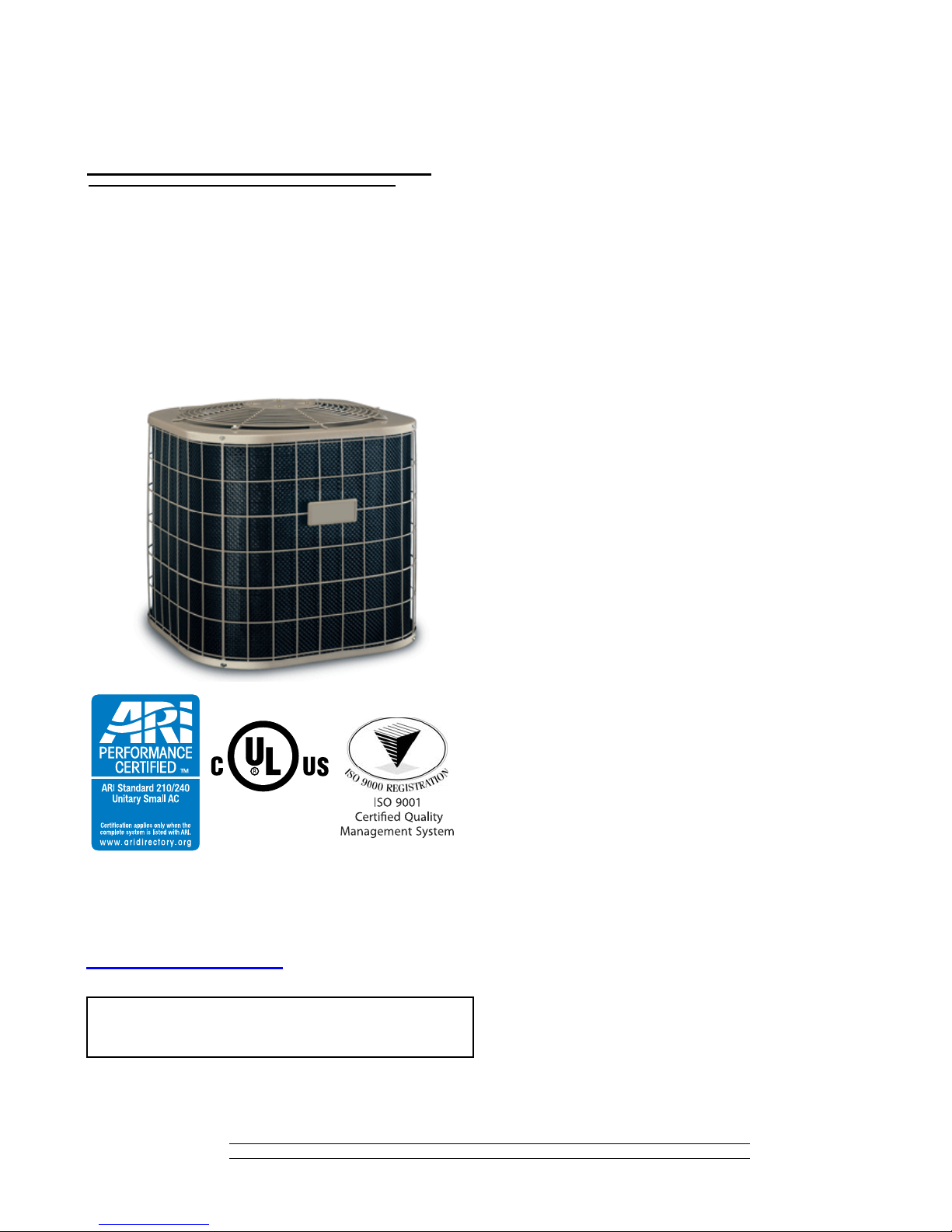
SPLIT-SYSTEM
AIR CONDITIONERS
13 SEER – R-410A
MODELS:
CCGD24 THRU 60
(2 THRU 5 NOMINAL TONS, 1 PHASE)
Due to continuous product improvement, specifications
are subject to change without notice.
Visit us on the web at www.york.com
Additional rating information can be found at
www.ahridirectory.org
WARRANTY
Standard 5-year limited parts warranty.
Standard 5-year limited compressor warranty.
LISTED
TECHNICAL
GUIDE
TECHNICAL
GUIDE
524447-BTG-A-0809
DESCRIPTION
The 13 SEER Series unit is the outdoor part of a versatile climate system. It is designed with a matching indoor coil component from Johnson Controls Unitary Products. Available for
typical applications this climate system is supported with accessories and documents to serve specific functions.
FEATURES
• QUALITY CONDENSER COILS - The coil is constructed of
aluminum microchannel tubing and enhanced aluminum fin s
for increased efficiency and corrosion protection.
• PROTECTED COMPRESSOR - The compressor is internally protected against high pressure and temperature. This
is accomplished by the simultaneous operation of high pressure relief valve and a temperature sensor which protects the
compressor if undesirable operating conditions occur. A liquid line filter-drier further protects the compressor.
• DURABLE FINISH - The cabinet is made of pre-painted
steel. The pre-treated galvanized steel provides a better
paint to steel bond, which resists corrosion and rust creep.
Special primer formulas and matted-textured finish insure
less fading when exposed to sunlight.
• LOWER INSTALLED COST - Installation time and costs are
reduced by easy power and control wiring connections. The
unit contains enough refrigerant for matching indoor coils.
The small base dimension means less space is required on
the ground or roof.
• TOP DISCHARGE - The warm air from the top mounted fan
is blown up away from the structure and any landscaping.
This allows compact location on multi-unit applications.
• LOW OPERATING SOUND LEVEL - The upward air flow
carries the normal operating noise away from the living area.
The rigid top panel effectively isolates any motor sound. Isolator mounted compressor and the rippled fins of the condenser coil muffle the normal fan motor and compressor
operating sounds.
• LOW MAINTENANCE - Long life permanently lubricated
motor-bearings need no annual servicing.
• EASY SERVICE ACCESS - Fully exposed refrigerant connections, a single panel covering the electrical controls, and
the molex plug in the control box connecting the condenser
fan make for easy servicing of the unit.
• FACTORY TESTED - to verify system operation and control
functioning before shipment.
• U.L. and C.U.L. listed - approved for outdoor application.
• Agency Listed - U.L. and C.U.L. listed - approved for outdoor application. The unit is certified in accordance with the
Unitary Small Equipment certification program, which is
based on ARI Standard 210/240.
FOR DISTRIBUTION USE ONLY - NOT TO BE USED AT POINT OF RETAIL SALE
Page 2

524447-BTG-A-0809
B
A
C
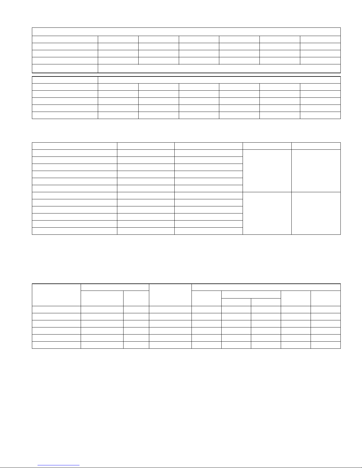
Physical and Electrical Data
MODEL CCGD24S41Q3 CCGD30S41Q3 CCGD36S41Q3 CCGD42S41Q3 CCGD48S41Q23 CCGD60S41Q3
Unit Supply Voltage 208-230V, 1 60Hz
Normal Voltage Range
1
Minimum Circuit Ampacity 12.4 14.7 17.9 21.5 21.1 34.3
Max. Overcurrent Device Amps
Min. Overcurrent Device Amps
2
3
20 25 30 35 35 60
15 15 20 25 25 35
Compressor Type Recip Recip Recip Recip Recip Scroll
Compressor Amps
Rated Load 9.3 10.6 13.1 16.0 15.7 26.2
Locked Rotor 43.0 54.0 74.0 84.0 84.0 150.0
Crankcase Heater No No No No No No
Fan Motor Amps Rated Load 17.5 17.5 22 22 22 24
Fan Diameter Inches 10 8 10 8 10 8 10 8 10 8 10 8
Minimum Wire Size
75° C Copper
(Max Length in Ft)
AWG 98 155 78 124 57 90 50 80 50 80 28 45
208V Max Length 108 172 86 137 63 100 55 88 55 88 31 49
230V Max Length 1 / 8 1 / 4 1 / 4 1 / 4 1 / 4 1 / 4
Rated HP 0.80 1.40 1.50 1.50 1.50 1.50
Fan Motor
Nominal RPM 1075 1100 850 850 850 850
Nominal CFM 1950 2050 3200 2950 2950 3600
Face Area Sq. Ft. 9.6 9.6 13.1 14.2 14.2 18.7
Coil
Rows Deep 1 1 1 1 1 1
Fin / Inches 23 23 23 23 23 23
Liquid Line Set OD (Field Installed) 3 / 8 3 / 8 3 / 8 3 / 8 3 / 8 3 / 8
Vapor Line Set OD (Field Installed) 3 / 4 3 / 4 3 / 4 7 / 8 7 / 8 7 / 8
Unit Charge (Lbs. - Oz.)
4
2 - 10 2 - 11 3 - 6 3 - 1 3 - 9 4 - 2
Charge Per Foot, Oz. 0.62 0.62 0.62 0.67 0.67 0.67
Operating Weight Lbs. 129 131 145 173 173 195
1.Rated in accordance with ARI Standard 110, utilization range “A”.
2.Dual element fuses or HACR circuit breaker. Maximum allowable overcurrent protection.
3.Dual element fuses or HACR circuit breaker. Minimum recommended overcurrent protection.
4.The Unit Charge is correct for the outdoor unit.
187 to 252
All dimensions are in inches. They are subject to change without notice.
Certified dimensions will be provided upon request.
.
Unit
Model
Dimensions
1
A
(Inches)
B C Liquid Vapor
Refrigerant Connection
Service Valve Size
24 28 23-1/2 23-1/2
3/4”30 28 23-1/2 23-1/2
36 28 29 29
42 30 29 29
3/8”
7/8”48 30 29 29
60 32 33-5/8 33-5/8
1.Including Fan Guard.
2 Johnson Controls Unitary Products
Page 3
524447-BTG-A-0809
System Charge for Various Matched Systems
Outdoor Unit CCGD24S41Q3 CCGD30S41Q3 CCGD36S41Q3 CCGD42S41Q3 CCGD48S41Q3 CCGD60S41Q3
Required Orifice or TXV 0.055 / 4F1 0.061 / 4F1 0.065 / 4G1 0.075 / 4G1 0.073 / 4H1 0.087 / 4J1
Factory R-22 Charge, lbs-oz 2 - 10 2 - 11 3 - 6 3 - 1 3 - 9 4 - 2
Rated CFM 800 1000 1200 1400 1600 1800
PreCharged Indoor Coils
Indoor Coil Additional Charge, Oz
FC/MC/PC35 –4463Q––––
FC/MC/PC36 4463Q–––––
FC/MC/PC43 – – 4463Q 4473Q – –
FC/MC/PC48 ––––4473Q –
FC/MC/PC60 –––––4473Q
Footnotes:
1. Match series number with table below for complete line set Part Number. (I.e. 2442- indicates 2442-8151 for a 15 ft installation requirement.
Pre-charged Refrigerant Line Set Line Set Length (ft) Factory R-22 charge lbs-oz Liquid Line Size Suction Line Size
4463Q1531 15 0 - 10
4463Q2031 20 0 - 13
4463Q2531 25 1 - 0
4463Q3031 30 1 - 3
4463Q4031 40 1 - 10
4463Q5031 50 2 - 0
4473Q1531 15 0 - 10
4473Q2031 20 0 - 13
4473Q2531 25 1 - 0
4473Q3031 30 1 - 3
4473Q4031 40 1 - 10
4473Q5031 50 2 - 0
Procedures:
1. Unit factory charge listed on the unit nameplate includes refrigerant for the condenser only.
2. Verify the pre-charged line set size and the additional charge required for the specific evaporator coil in the system using the above table.
3. Permanently mark the unit nameplate with the total system charge. Total System Charge = Base charge (as shipped) + 8 oz for Indoor
coil + charge for line set.
Pre-charged Refrigerant Line Set1 See Table Below
3 / 8 3 / 4
3 / 8 7 / 8
COOLING CAPACITY - Upflow, Downflow & Horizontal Furnaces and Coils
FURNACE
UNIT MODEL
CCGD24S41Q3 600 - 1000 14,17,21 FC/MC/PC36 800 24.0 16.7 13.00 11.00
CCGD30S41Q3 800 - 1200 17,21 FC/MC/PC35 1000 29.0 21.0 13.00 11.00
CCGD36S41Q3 1000 - 1400 17,21 FC/MC/PC43 1200 35.0 24.8 13.00 11.00
CCGD42S41Q3 1200 - 1600 17,21 FC/MC/PC43 1400 42.0 29.2 13.00 11.00
CCGD48S41Q3 1400 - 1800 21,24 FC/MC/PC48 1600 48.0 34.4 13.00 11.00
CCGD60S41Q3 1600 - 2000 21,24 FC/MC/PC60 1800 57.0 38.5 13.00 11.00
1. Requires a 2FD06700224 Blower Time Delay unless a standard furnace is equipped with one.
CFM RANGE
(Min.-max.)
W
COIL
MODEL
RATED
CFM
TOTAL SENS.
Johnson Controls Unitary Products 3
COOLING
NET MBH
SEER
1
EER
Page 4

524447-BTG-A-0809
MINIMUM 18” SERVICE ACCESS
CLEARANCE ON ONE SIDE
60” OVERHEAD
CLEARANCE
6” CLEARANCE
COIL AREA
WEATHERPROOF
DISCONNECT
SWITCH
THERMOSTAT
TO FURNACE OR
AIR HANDLER
TERMINAL BLOCK
NEC CLASS 1 WIRING
NEC CLASS 2 WIRING
TO INDOOR COIL
SEAL OPENING(S) WITH
PERMAGUM OR EQUIVALENT
NOTE: ALL OUTDOOR WIRING MUST BE
POSSIBLE OUTDOOR THERMOSTAT KIT LOCATIONS
(UNIT MOUNTING NOT AVAILABLE ON ALL MODELS)
ALL FIELD WIRING TO BE IN ACCORDANCE WITH ELECTRIC CODE (NEC) AND/OR LOCAL CODES
POWER WIRING
208/230-1-60
CONTACTOR
TERMINALS
COIL
GND.
LUG
CYRGW
Y
R
GW
POWER WIRING
CONTROL WIRING
FACTORY WIRING
24 VOLT CONTROL WIRING
MINIMUM 18 GA. WIRE
(NEC CLASS 2)
FURNACE OR AIR HANDLER TERMINAL BLOCK
ROOM THERMOSTAT
CONDENSING UNIT
ALL OUTDOOR WIRING MUST BE WEATHERPROOF. USE COPPER CONDUCTORS ONLY.
TERMINAL W IS ONLY
REQUIRED ON SYSTEMS
WITH HEAT.
*
*
ACCESSORIES
Refer to Price Manual for specific model numbers.
Off Cycle Timer Delay - Provides a 5-minute off cycle to pre-
vent rapid recycling of the compressor.
Hard Start Kit - Required when using TXV indoor coil. Also,
provides increased starting torque for areas with low voltage.
Model Source 1 Kit numbers
24 S1-2SA06721706
30 S1-2SA06705906
36 S1-2SA06708906
42 S1-2SA06708806
48 S1-2SA06708806
60 S1-2SA06707906
TYPICAL INSTALLATION
Thermostats - Compatible thermostat controls are available
through accessory sourcing. For optimum performance and
installation, refer to the UPGNET “Low Voltage Wiring Diagram”
document to select and apply controls.
SOUND POWER RATINGS*
Unit Model (dBA)
24 76
30 76
36 76
42 76
48 77
60 78
* Rated in accordance with ARI 270-95 Standards.
TYPICAL FIELD WIRING
4 Johnson Controls Unitary Products
Page 5

524447-BTG-A-0809
COOLING PERFORMANCE DATA
AIR CONDITIONER MODEL NO. CCGD24S41Q3
INDOOR COIL MODEL NO. FC/MC/PC36
CONDENSING
ENTERING AIR
TEMPERATURE
65
75
85
95
105
115
125
NOTE: ALL CAPACITIES INCLUDE INDOOR FAN HEAT AT 1250 BTUH/1000 CFM.
NOTE: For dry bulb temperatures different than those listed (between 73-87 F), sensible capacity increases by 1060 BTUH per 1000 CFM per degree above the listed
temperature and decreases by 1060 BTUH per 1000 CFM per degree below the listed temperature.
IDCFM 600 800 1000
ID DB (°F) 80 80 75 80 80 80 80 75 80 80 80 80 75 80 80
ID WB (°F) 57 62 62 67 72 57 62 62 67 72 57 62 62 67 72
T.C. 22.0 27.4 27.3 29.1 30.3 24.3 28.8 28.6 30.4 31.7 26.6 30.1 29.8 31.8 33.2
S.C. 22.0 19.9 17.3 17.0 13.8 24.2 22.9 19.6 18.8 14.8 26.4 26.0 22.0 20.6 15.7
KW 1.5 1.5 1.5 1.5 1.5 1.5 1.5 1.5 1.5 1.5 1.5 1.5 1.5 1.5 1.5
T.C. 20.5 25.3 25.1 27.4 29.3 23.0 26.9 26.6 28.9 30.7 25.5 28.4 28.0 30.4 32.2
S.C. 20.5 19.3 16.4 16.5 13.4 22.8 22.1 18.8 18.4 14.4 25.1 24.9 21.3 20.3 15.5
KW 1.6 1.6 1.6 1.6 1.6 1.6 1.6 1.6 1.6 1.6 1.6 1.6 1.6 1.6 1.6
T.C. 19.0 23.2 23.0 25.8 28.3 21.7 25.0 24.6 27.4 29.7 24.4 26.7 26.1 28.9 31.2
S.C. 19.0 18.6 15.6 15.9 12.9 21.4 21.2 18.1 18.0 14.1 23.9 23.7 20.5 20.0 15.3
KW 1.7 1.7 1.7 1.7 1.8 1.7 1.7 1.7 1.8 1.8 1.7 1.7 1.7 1.8 1.8
T.C. 17.5 21.1 20.8 23.8 27.2 20.4 23.1 22.5 24.0 28.7 23.3 25.0 24.3 27.5 30.1
S.C. 17.5 18.0 14.7 15.4 12.4 20.0 20.3 17.3 16.8 13.7 22.6 22.6 19.8 19.7 15.1
KW 1.8 1.8 1.8 1.9 1.9 1.9 1.9 1.9 1.9 1.9 1.9 1.9 1.9 1.9 2.0
T.C. 16.2 19.0 18.4 21.7 24.8 18.7 21.0 20.2 23.3 26.3 21.3 22.9 22.0 24.9 27.7
S.C. 16.1 16.6 13.7 14.4 11.6 18.4 18.6 15.9 16.6 13.0 20.6 20.6 18.2 18.8 14.5
KW 2.0 2.0 2.0 2.0 2.1 2.0 2.0 2.0 2.0 2.1 2.0 2.0 2.0 2.1 2.1
T.C. 14.8 17.0 16.1 19.3 22.5 17.1 18.9 17.9 20.8 23.9 19.4 20.9 19.7 22.3 25.4
S.C. 14.8 15.3 12.7 13.5 10.8 16.8 17.0 14.6 15.7 12.4 18.7 18.7 16.5 17.8 13.9
KW 2.1 2.1 2.1 2.1 2.2 2.1 2.1 2.1 2.2 2.2 2.2 2.2 2.1 2.2 2.3
T.C. 13.5 14.9 13.8 16.8 20.1 15.5 16.9 15.6 18.3 21.6 17.5 18.9 17.4 19.8 23.1
S.C. 13.5 13.9 11.7 12.5 10.1 15.1 15.4 13.3 14.7 11.7 16.8 16.8 14.9 16.9 13.3
KW 2.2 2.2 2.2 2.3 2.4 2.3 2.3 2.2 2.3 2.4 2.3 2.3 2.3 2.3 2.4
COOLING PERFORMANCE DATA
AIR CONDITIONER MODEL NO. CCGD30S41Q3
INDOOR COIL MODEL NO. FC/MC/PC35
CONDENSING
ENTERING AIR
TEMPERATURE
65
75
85
95
105
115
125
NOTE: ALL CAPACITIES INCLUDE INDOOR FAN HEAT AT 1250 BTUH/1000 CFM.
NOTE: For dry bulb temperatures different than those listed (between 73-87 F), sensible capacity increases by 1060 BTUH per 1000 CFM per degree above the listed
temperature and decreases by 1060 BTUH per 1000 CFM per degree below the listed temperature.
IDCFM 800 1000 1200
ID DB (°F) 80 80 75 80 80 80 80 75 80 80 80 80 75 80 80
ID WB (°F) 57 62 62 67 72 57 62 62 67 72 57 62 62 67 72
T.C. 28.4 31.4 30.8 33.1 34.4 29.8 31.8 31.4 33.4 34.5 31.2 32.3 32.1 33.7 34.7
S.C. 28.8 25.8 21.7 21.2 16.0 30.4 28.2 23.6 22.6 17.1 31.9 30.7 25.4 24.0 18.1
KW 1.7 1.7 1.7 1.7 1.7 1.7 1.7 1.7 1.7 1.7 1.7 1.7 1.7 1.7 1.7
T.C. 26.4 28.8 28.2 30.9 32.6 27.9 29.7 28.9 31.4 32.8 29.5 30.5 29.6 31.8 32.9
S.C. 26.9 24.7 20.5 20.3 15.4 28.5 27.1 22.6 22.0 16.4 30.2 29.5 24.6 23.7 17.5
KW 1.8 1.8 1.8 1.9 1.9 1.8 1.8 1.8 1.9 1.9 1.9 1.9 1.9 1.9 1.9
T.C. 24.4 26.3 25.6 28.8 30.9 26.0 27.5 26.4 29.3 31.0 27.7 28.7 27.1 29.8 31.2
S.C. 24.9 23.6 19.4 19.4 14.7 26.6 26.0 21.6 21.4 15.8 28.4 28.4 23.9 23.4 16.8
KW 2.0 2.0 2.0 2.0 2.1 2.0 2.0 2.0 2.0 2.1 2.0 2.0 2.0 2.1 2.1
T.C. 22.4 23.8 23.0 26.7 29.1 24.2 25.3 23.8 29.0 29.3 26.0 26.9 24.7 27.9 29.4
S.C. 22.9 22.5 18.2 18.5 14.1 24.8 24.9 20.7 21.2 15.1 26.7 27.3 23.1 23.1 16.2
KW 2.1 2.1 2.1 2.2 2.3 2.2 2.2 2.2 2.2 2.3 2.2 2.2 2.2 2.2 2.3
T.C. 20.5 21.8 20.4 23.7 26.3 22.0 23.1 21.3 24.3 26.4 23.6 24.5 22.1 24.8 26.4
S.C. 21.0 20.7 17.1 17.4 13.2 22.6 22.7 19.1 19.7 14.3 24.3 24.7 21.0 22.0 15.4
KW 2.3 2.3 2.3 2.4 2.4 2.4 2.4 2.3 2.4 2.5 2.4 2.4 2.3 2.4 2.5
T.C. 18.6 19.8 17.9 20.9 23.5 19.9 21.0 18.8 21.4 23.5 21.2 22.2 19.6 21.8 23.6
S.C. 19.1 18.9 15.9 16.4 12.3 20.5 20.5 17.5 18.6 13.5 22.0 22.2 19.1 20.9 14.7
KW 2.5 2.5 2.4 2.5 2.6 2.5 2.5 2.5 2.5 2.6 2.6 2.6 2.5 2.6 2.6
T.C. 16.8 17.9 15.4 18.1 20.7 17.8 18.9 16.2 18.5 20.7 18.9 19.9 17.1 18.8 20.7
S.C. 17.3 17.2 14.8 15.3 11.4 18.4 18.4 16.0 17.6 12.6 19.6 19.6 17.1 19.8 13.9
KW 2.7 2.7 2.6 2.7 2.8 2.7 2.7 2.6 2.7 2.8 2.7 2.7 2.7 2.7 2.8
Johnson Controls Unitary Products 5
Page 6

524447-BTG-A-0809
COOLING PERFORMANCE DATA
AIR CONDITIONER MODEL NO. CCGD36S41Q3
INDOOR COIL MODEL NO. FC/MC/PC43
CONDENSING
ENTERING AIR
TEMPERATURE
65
75
85
95
105
115
125
NOTE: ALL CAPACITIES INCLUDE INDOOR FAN HEAT AT 1250 BTUH/1000 CFM.
NOTE: For dry bulb temperatures different than those listed (between 73-87 F), sensible capacity increases by 1060 BTUH per 1000 CFM per degree above the listed
temperature and decreases by 1060 BTUH per 1000 CFM per degree below the listed temperature.
IDCFM 1000 1200 1400
ID DB (°F) 80 80 75 80 80 80 80 75 80 80 80 80 75 80 80
ID WB (°F) 57 62 62 67 72 57 62 62 67 72 57 62 62 67 72
T.C. 34.7 36.1 35.2 37.4 37.3 33.8 35.5 34.8 37.0 37.5 32.9 34.9 34.4 36.6 37.6
S.C. 34.3 33.0 27.6 25.5 18.4 33.3 31.0 26.2 24.6 18.0 32.3 29.1 24.7 23.6 17.7
KW 2.0 2.0 2.0 2.0 2.0 2.0 2.0 2.0 2.0 2.0 1.9 2.0 1.9 2.0 2.0
T.C. 33.6 34.7 33.6 35.9 36.6 32.6 33.9 33.2 35.5 36.6 31.5 33.2 32.7 35.1 36.6
S.C. 33.3 32.5 27.5 25.6 18.6 32.1 30.6 25.8 24.5 18.0 31.0 28.7 24.2 23.3 17.5
KW 2.2 2.2 2.2 2.2 2.2 2.2 2.2 2.2 2.2 2.2 2.1 2.2 2.2 2.2 2.2
T.C. 32.4 33.2 32.0 34.4 35.8 31.3 32.3 31.5 34.1 35.7 30.2 31.5 31.0 33.7 35.5
S.C. 32.2 32.0 27.3 25.8 18.8 30.9 30.2 25.5 24.3 18.0 29.6 28.3 23.7 22.9 17.3
KW 2.4 2.4 2.4 2.4 2.4 2.4 2.4 2.4 2.4 2.4 2.3 2.4 2.4 2.4 2.4
T.C. 31.3 31.7 30.4 33.0 35.0 30.1 30.7 29.9 35.0 34.8 28.9 29.8 29.4 32.2 34.5
S.C. 31.1 31.5 27.2 26.0 19.0 29.7 29.7 25.2 24.9 18.0 28.3 27.9 23.2 22.5 17.1
KW 2.6 2.6 2.6 2.6 2.7 2.6 2.6 2.6 2.6 2.7 2.5 2.6 2.6 2.6 2.6
T.C. 27.9 28.8 27.2 29.8 32.5 27.0 27.8 26.6 29.4 32.2 26.0 26.9 25.9 29.0 31.9
S.C. 28.7 28.9 25.0 25.0 18.4 27.3 27.2 23.2 23.2 17.3 25.8 25.6 21.5 21.4 16.2
KW 2.8 2.8 2.8 2.8 2.9 2.8 2.8 2.8 2.8 2.9 2.7 2.8 2.7 2.8 2.9
T.C. 24.6 26.0 24.2 26.8 30.1 23.9 25.1 23.4 26.3 29.8 23.3 24.1 22.6 25.9 29.5
S.C. 26.3 26.3 22.8 24.1 17.8 24.9 24.8 21.3 22.2 16.6 23.5 23.3 19.8 20.3 15.4
KW 3.0 3.0 3.0 3.0 3.1 3.0 3.0 2.9 3.0 3.1 2.9 2.9 2.9 3.0 3.1
T.C. 21.3 23.2 21.1 23.7 27.6 20.9 22.3 20.2 23.2 27.3 20.5 21.3 19.3 22.7 27.0
S.C. 23.9 23.8 20.6 23.2 17.2 22.5 22.4 19.4 21.2 15.9 21.1 21.0 18.2 19.2 14.6
KW 3.2 3.2 3.2 3.2 3.4 3.2 3.2 3.1 3.2 3.3 3.1 3.1 3.1 3.2 3.3
COOLING PERFORMANCE DATA
AIR CONDITIONER MODEL NO. CCGD42S41Q3
INDOOR COIL MODEL NO. FC/MC/PC43
CONDENSING
ENTERING AIR
TEMPERATURE
65
75
85
95
105
115
125
NOTE: ALL CAPACITIES INCLUDE INDOOR FAN HEAT AT 1250 BTUH/1000 CFM.
NOTE: For dry bulb temperatures different than those listed (between 73-87 F), sensible capacity increases by 1060 BTUH per 1000 CFM per degree above the listed
temperature and decreases by 1060 BTUH per 1000 CFM per degree below the listed temperature.
IDCFM 1200 1400 1600
ID DB (°F) 80 80 75 80 80 80 80 75 80 80 80 80 75 80 80
ID WB (°F) 57 62 62 67 72 57 62 62 67 72 57 62 62 67 72
T.C. 44.4 45.5 43.6 47.0 48.5 45.9 46.5 45.0 48.5 49.8 47.5 47.5 46.5 50.1 51.1
S.C. 41.5 35.6 29.7 28.7 21.5 42.9 37.5 31.4 30.2 22.9 44.4 39.4 33.2 31.7 24.3
KW 2.5 2.5 2.5 2.5 2.5 2.5 2.5 2.5 2.5 2.6 2.5 2.5 2.5 2.5 2.6
T.C. 42.3 42.9 41.2 45.1 46.6 44.2 44.3 42.7 46.6 47.9 46.0 45.7 44.2 48.1 49.1
S.C. 39.4 35.2 29.2 28.5 21.3 41.1 37.4 31.1 30.1 22.4 42.9 39.7 33.0 31.8 23.6
KW 2.7 2.7 2.7 2.8 2.8 2.7 2.7 2.7 2.8 2.8 2.8 2.8 2.8 2.8 2.9
T.C. 40.2 40.3 38.9 43.3 44.6 42.4 42.1 40.4 44.7 45.9 44.6 43.9 41.9 46.0 47.2
S.C. 37.2 34.7 28.7 28.2 21.2 39.3 37.3 30.8 30.0 22.0 41.5 40.0 32.9 31.8 22.9
KW 3.0 3.0 3.0 3.0 3.1 3.0 3.0 3.0 3.1 3.1 3.0 3.0 3.0 3.1 3.1
T.C. 38.2 37.7 36.5 41.5 42.7 40.7 39.9 38.0 42.0 44.0 43.2 42.1 39.6 43.9 45.3
S.C. 35.0 34.3 28.1 28.0 21.0 37.5 37.3 30.5 29.4 21.6 40.0 40.3 32.8 31.9 22.2
KW 3.2 3.2 3.2 3.3 3.4 3.3 3.3 3.3 3.3 3.4 3.3 3.3 3.3 3.4 3.4
T.C. 35.3 34.7 32.8 37.4 38.7 37.5 36.7 34.2 38.6 39.8 39.8 38.8 35.6 39.8 40.9
S.C. 32.3 32.1 26.5 26.4 19.6 34.5 34.5 28.8 28.4 20.4 36.7 37.0 31.1 30.5 21.2
KW 3.5 3.5 3.5 3.6 3.7 3.5 3.5 3.5 3.6 3.7 3.6 3.6 3.5 3.6 3.7
T.C. 32.4 31.7 29.2 33.4 34.8 34.5 33.6 30.5 34.6 35.7 36.5 35.5 31.8 35.7 36.7
S.C. 29.7 30.0 25.0 24.9 18.2 31.6 31.9 27.2 27.0 19.3 33.5 33.8 29.4 29.1 20.3
KW 3.7 3.7 3.7 3.8 4.0 3.8 3.8 3.7 3.8 4.0 3.8 3.8 3.7 3.9 4.0
T.C. 29.6 28.8 25.6 29.4 30.9 31.4 30.5 26.8 30.5 31.7 33.2 32.2 28.0 31.7 32.5
S.C. 27.1 27.9 23.5 23.4 16.8 28.7 29.3 25.6 25.6 18.1 30.2 30.6 27.6 27.8 19.4
KW 4.0 4.0 3.9 4.0 4.2 4.0 4.0 4.0 4.1 4.3 4.1 4.1 4.0 4.1 4.3
6 Johnson Controls Unitary Products
Page 7

524447-BTG-A-0809
COOLING PERFORMANCE DATA
AIR CONDITIONER MODEL NO. CCGD48S41Q3
INDOOR COIL MODEL NO. FC/MC/PC48
CONDENSING
ENTERING AIR
TEMPERATURE
65
75
85
95
105
115
125
NOTE: ALL CAPACITIES INCLUDE INDOOR FAN HEAT AT 1250 BTUH/1000 CFM.
NOTE: For dry bulb temperatures different than those listed (between 73-87 F), sensible capacity increases by 1060 BTUH per 1000 CFM per degree above the listed
temperature and decreases by 1060 BTUH per 1000 CFM per degree below the listed temperature.
IDCFM 1400 1600 1800
ID DB (°F) 80 80 75 80 80 80 80 75 80 80 80 80 75 80 80
ID WB (°F) 57 62 62 67 72 57 62 62 67 72 57 62 62 67 72
T.C. 49.7 51.4 50.6 55.8 54.6 52.0 53.1 51.9 56.4 55.4 54.4 54.7 53.2 56.9 56.3
S.C. 47.2 43.1 35.9 36.0 26.1 49.2 45.9 38.2 37.4 27.6 51.2 48.7 40.4 38.8 29.0
KW 2.7 2.8 2.8 2.8 2.8 2.7 2.8 2.8 2.8 2.8 2.7 2.8 2.8 2.8 2.9
T.C. 47.5 48.6 47.7 52.9 52.4 49.8 50.3 48.9 53.6 53.1 52.0 52.1 50.2 54.3 53.8
S.C. 44.9 42.0 35.0 34.9 25.4 47.0 44.8 37.1 36.5 26.8 49.0 47.6 39.3 38.2 28.1
KW 3.0 3.0 3.0 3.1 3.1 3.0 3.0 3.0 3.1 3.2 3.0 3.0 3.0 3.1 3.2
T.C. 45.4 45.8 44.8 49.9 50.2 47.5 47.6 46.0 50.8 50.8 49.7 49.4 47.1 51.7 51.4
S.C. 42.7 41.0 34.0 33.8 24.8 44.7 43.7 36.1 35.7 26.0 46.8 46.5 38.2 37.6 27.2
KW 3.2 3.3 3.3 3.4 3.4 3.3 3.3 3.3 3.4 3.5 3.3 3.3 3.3 3.4 3.5
T.C. 43.2 42.9 42.0 47.0 47.9 45.3 44.9 43.1 48.0 48.4 47.4 46.8 44.1 49.1 48.9
S.C. 40.4 39.9 33.0 32.7 24.1 42.4 42.6 35.1 34.6 25.2 44.5 45.4 37.1 37.0 26.3
KW 3.5 3.5 3.5 3.6 3.7 3.6 3.6 3.5 3.7 3.8 3.6 3.6 3.6 3.7 3.8
T.C. 39.8 39.4 37.3 42.4 43.6 41.6 41.1 38.4 43.4 44.0 43.5 42.9 39.5 44.4 44.5
S.C. 37.1 37.0 30.9 30.9 22.9 38.9 39.3 32.9 33.0 23.9 40.8 41.5 34.9 35.1 25.0
KW 3.8 3.8 3.8 3.9 4.0 3.9 3.9 3.8 3.9 4.1 3.9 3.9 3.8 4.0 4.1
T.C. 36.5 35.9 32.7 38.0 39.3 38.1 37.5 33.9 38.9 39.8 39.7 39.1 35.1 39.8 40.2
S.C. 33.9 34.2 28.9 29.2 21.6 35.5 36.0 30.9 31.3 22.7 37.2 37.7 32.8 33.3 23.8
KW 4.1 4.1 4.0 4.2 4.3 4.1 4.1 4.1 4.2 4.4 4.2 4.2 4.1 4.2 4.4
T.C. 33.1 32.4 28.1 33.5 35.1 34.5 33.8 29.4 34.4 35.5 35.9 35.3 30.6 35.2 36.0
S.C. 30.7 31.4 26.9 27.5 20.4 32.1 32.7 28.8 29.6 21.5 33.5 34.0 30.7 31.6 22.5
KW 4.4 4.4 4.3 4.4 4.6 4.4 4.4 4.3 4.5 4.7 4.5 4.5 4.4 4.5 4.7
COOLING PERFORMANCE DATA
AIR CONDITIONER MODEL NO. CCGD60S41Q3
INDOOR COIL MODEL NO. FC/MC/PC60
CONDENSING
ENTERING AIR
TEMPERATURE
65
75
85
95
105
115
125
NOTE: ALL CAPACITIES INCLUDE INDOOR FAN HEAT AT 1250 BTUH/1000 CFM.
NOTE: For dry bulb temperatures different than those listed (between 73-87 F), sensible capacity increases by 1060 BTUH per 1000 CFM per degree above the listed
temperature and decreases by 1060 BTUH per 1000 CFM per degree below the listed temperature.
IDCFM 1600 1800 2000
ID DB (°F) 80 80 75 80 80 80 80 75 80 80 80 80 75 80 80
ID WB (°F) 57 62 62 67 72 57 62 62 67 72 57 62 62 67 72
T.C. 55.8 63.8 62.1 65.2 71.9 60.3 65.7 62.8 66.7 69.8 64.8 67.5 63.5 68.2 67.8
S.C. 54.7 51.6 41.4 41.1 34.1 58.4 54.2 43.9 42.6 31.9 62.1 56.8 46.5 44.2 29.6
KW 3.0 3.0 3.0 3.1 3.1 3.0 3.0 3.0 3.1 3.1 3.0 3.1 3.0 3.1 3.1
T.C. 56.9 61.1 58.9 62.7 69.7 59.2 63.0 59.9 64.3 67.9 61.4 64.9 61.0 65.9 66.0
S.C. 53.9 50.4 40.5 40.0 33.5 55.8 53.1 43.1 41.8 31.5 57.7 55.7 45.6 43.6 29.5
KW 3.4 3.5 3.5 3.5 3.6 3.4 3.5 3.5 3.5 3.5 3.5 3.5 3.5 3.5 3.5
T.C. 58.0 58.4 55.7 60.3 67.6 58.0 60.4 57.1 61.9 65.9 58.1 62.4 58.5 63.6 64.1
S.C. 53.2 49.3 39.7 39.0 32.9 53.3 52.0 42.2 41.0 31.2 53.4 54.7 44.8 42.9 29.4
KW 3.9 3.9 3.9 3.9 4.0 3.9 3.9 3.9 3.9 4.0 3.9 3.9 3.9 3.9 4.0
T.C. 59.1 55.7 52.5 56.9 65.5 56.9 57.8 54.3 57.0 63.9 54.7 59.8 56.0 61.2 62.2
S.C. 52.4 48.1 38.8 37.9 32.3 50.7 50.9 41.4 38.8 30.8 49.0 53.6 43.9 42.3 29.4
KW 4.3 4.3 4.3 4.4 4.5 4.3 4.3 4.3 4.4 4.4 4.3 4.3 4.3 4.4 4.4
T.C. 56.4 52.2 48.8 54.0 60.1 54.0 54.3 50.5 55.7 59.7 51.6 56.3 52.2 57.4 59.4
S.C. 49.7 45.9 37.5 36.5 29.7 47.9 48.3 40.0 38.7 29.4 46.2 50.6 42.5 40.9 29.0
KW 4.9 4.9 4.9 4.9 5.0 4.9 4.9 4.9 5.0 5.0 4.9 4.9 4.9 5.0 5.0
T.C. 53.8 48.8 45.2 50.2 54.8 51.2 50.9 46.8 51.9 55.7 48.7 53.0 48.5 53.6 56.6
S.C. 47.1 43.8 36.2 35.0 27.3 45.3 45.7 38.6 37.3 27.9 43.5 47.7 41.1 39.6 28.6
KW 5.5 5.4 5.4 5.5 5.6 5.5 5.5 5.4 5.5 5.6 5.4 5.5 5.4 5.5 5.6
T.C. 51.2 45.4 41.6 46.5 49.4 48.5 47.5 43.2 48.2 51.6 45.7 49.7 44.8 49.8 53.8
S.C. 44.5 41.7 34.9 33.6 24.9 42.6 43.2 37.3 35.9 26.5 40.7 44.7 39.7 38.3 28.2
KW 6.1 6.0 5.9 6.1 6.2 6.0 6.0 6.0 6.1 6.2 6.0 6.0 6.0 6.1 6.2
Johnson Controls Unitary Products 7
Page 8

Subject to change without notice. Published in U.S.A. 524447-BTG-A-0809
Copyright © 2009 by Johnson Controls, Inc. All rights reserved. Supersedes: 400040-BTG-A-0408
Johnson Controls Unitary Products
P.O. Box 19014
Wichita, KS 67204-9014
 Loading...