

Page 1
BackHome
®
Pavilion
11’ 3” x11’ 3”
Instructions apply to Part Number 9392-136
Things you should know:
Read all instructions before set-up.
Pavilion can be staked down or bolted down.
Initial frame set-up may be done upright or upside down.
Page 2
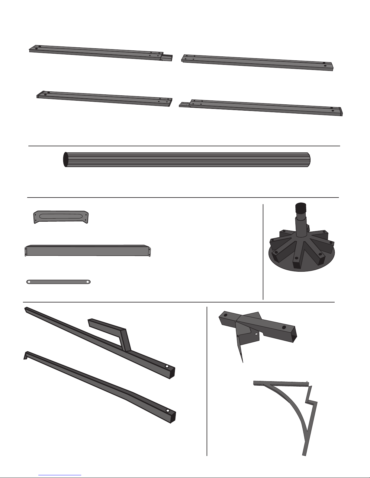
Dual Track w/ End Cap
Part: B2 (Qty.: 2)
Part No.: 9392-2531
Dual Track w/out End Cap
Part: A1 (Qty.: 2)
Part No.: 9392-2501
Dual Track w/out End Cap
Part: A2 (Qty.: 2)
Part No.: 9392-2511
Fluted Columns w/ End Caps
Part: C (Qty.: 4)
Part No.: 9392-2541
Dual Track Corner Brace – Small
Part: D (Qty.: 4)
Part No.: 9392-2551
Dual Track Corner Brace – Large
Part: E (Qty.: 4)
Part No.: 9392-2561
Center Hub
Part: G (Qty.: 1)
Part No.: 9392-2581
Corner Brackets
Part: J (Qty.: 4)
Part No.: 9392-2611
Planter Hooks
Part: K (Qty.: 4)
Part No.: 9392-2621
Track/Column Brace
Part: F (Qty.: 8)
Part No.: 9392-2571
Corner Roof Pole
Part: H (Qty.: 4)
Part No.: 9392-2591
Side Roof Pole
Part: I (Qty.: 4)
Part No.: 9392-2601
Dual Track w/ End Cap
Part: B1 (Qty.: 2)
Part No.: 9392-2521
2
Parts List
Page 3
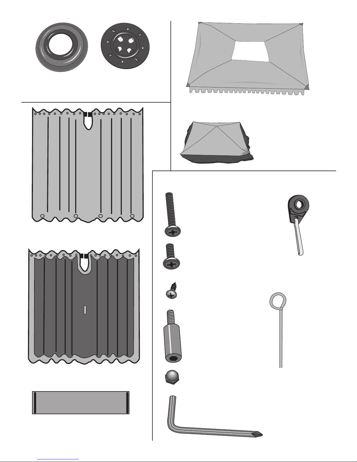
Decorative Plates
Part: L (Qty.: 4)
Part No.: 9392-2631
Mounting Plates
Part: M (Qty.: 4)
Part No.: 9392-2641
Allen Wrench/
Phillips Screwdriver
Included
Other Suggested Tools:
Power screwdriver with
Phillips Head attachment
For more permanent
mounting, utilize the
appropriate anchor bolts
for your particular
application (not provided).
Canopy – (Qty.: 1)
Part No.: 9392-2651
Privacy Walls (Qty.: 4)
Part No.: 9392-2661
Tie Backs (Qty.: 4)
Part No.: 9392-2691
Phillips Head Machine
Screws – Large (Qty.: 46)
Part No.: 9392-2701
Note: Extra fastener are included for your convenience.
Phillips Head Machine
Screws – Small (Qty.: 26)
Part No.: 9392-2711
Phillips Head Sheet
Metal Screws – Small
(Qty.: 75)
Part No.: 9392-2721
Long Hex Head Cap
Screw (Qty.: 21)
Part No.: 9392-2731
Acorn Nuts (Qty.: 51)
Part No.: 9392-2741
Track Hooks
(Qty.: 101)
Part No.: 9392-2751
Screen Walls (Qty.: 4)
Part No.: 9392-2671
Roof Vent Cover (Qty.: 1)
Part No.: 9392-2681
Stakes
(Qty.: 32)
Part No.:
9392-2761
3
Page 4
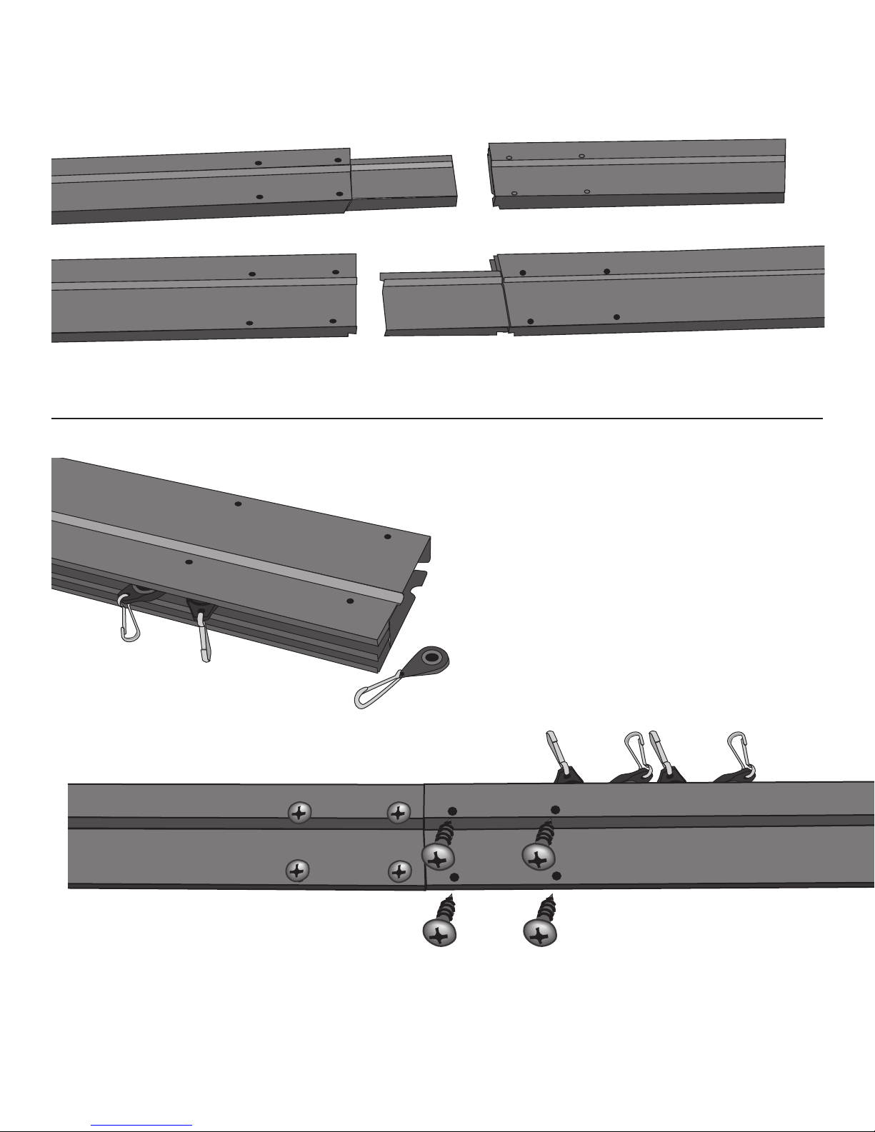
Sort Dual Track Pieces: Layout so that the tracks are all going the the same direction.
A1 (male) matches to A2 (without end cap) and B1 to B2 (with end cap).
Add track hooks. Insert 12 hooks
per track per frame side (24 hooks
each side). It will be easier to
attach the side walls if the hooks
are inserted with the opening to the
grooved side of the track. (illus. 2)
Connect the matching Dual Track pieces A1 to A2 and B1 to B2 and secure with 4 Phillips Head Sheet
Metal Screws – Small. Track Side should be facing the same way on both pieces. Repeat for all other
Dual Track sections.
illus. 1
illus. 2
illus. 3
Set Up Instructions
Phillips Head Sheet Metal Screws _ Small
4
Page 5

Attach the Dual Track sections to the Columns with the Long Hex Cap Screws (16) by
lining up the pre-drilled holes and hand tightening the screws. There are screw holes on
two sides of the column, make sure that one set of screw holes is facing out and one set
is pointing up. DO NOT FULLY TIGHTEN. Assembled Dual Track A sections will go on
opposites side from each other. (see illus. 5)
Dual Track side with hooks
End cap
Long Hex
Cap Screw
B1&B2
B1 & B2
A1 & A2
A1 & A2
illus. 4
illus. 5
Notice that A and B sections are both opposite each other. Leave frame hand tightened
only at this point.
5
Page 6

Dual Track Corner Brace – Small (D)
Attach the Small corner brace to the
column with 2 Phillips Head Machine
Screws – Small.
From the outside of the frame insert 4
Phillips Head Machine Screws – Large
through the Dual Track and Small
Corner Brace and secure with 4
Acorn Nuts. (illus. 6)
Repeat for other 3 corners.
Dual Track Corner Brace – Large (E)
From the outside of the frame insert 4
Phillips Head Machine Screws – Large
through the Dual Track and Small
Corner Brace and secure with 4
Acorn Nuts. (illus. 7)
Repeat for other 3 corners.
Track/Column Brace (F)
Position the Track/Column Brace (F)
on the inside of the Dual Track and the
outside of the Column. Secure to the
Column with Phillips Head Machine
Screw – Small. Insert Phillips Head
Machine Screw – Large through the Dual
Track from the outside and attach Acorn
Nut on open end. Repeat for second
Track/Column Brace on other side of
corner (illus. 8).
Repeat for other 3 corners.
illus. 6
illus. 7
illus. 8
(E)
(D)
(F)
Phillips Head Machine
Screws – Large
Phillips Head Machine
Screws – Small
Phillips Head
Machine
Screws – Small
Note: Brace attaches to the inside of the dual track
and to the outside of the column.
Phillips Head Machine
Screws – Large
Phillips Head Machine
Screws – Large
6
Page 7

Tool tighten all the Long Hex Head Cap
Screws connecting the Dual Tracks and the
Columns. Tool tighten all bolts and nuts.
Completed frame upside down. (illus. 9)
Flip frame upright. Requires 2 to 4 people
Note: Frame can be assembled in upright
position from the beginning if preferred.Simply
follow the same directions, but note that the
illustrations to this point are upside down.
(illus. 10)
Center Hub (G)
Corner Roof Pole (H)
Side Roof Pole (I)
Attach the 4 Corner Roof Poles (H)
and the 4 Side Roof Poles (I) by
inserting the button end into the Hub
until it locks into position.
Alternate Corner Roof, Side Roof,
Corner Roof...until the Hub is
complete. (illus. 11)
illus. 9
illus.10
illus.11
(G)
(H)
(I)
7
Page 8

Roof Vent Cover
Drape the Roof Vent Cover over
the Hub positioning the peak over
the center on the Hub.
Lift the corner of the Roof Vent
Cover and pull over the short
end of the Corner Roof Pole to
insert the pole into the underside
corner pocket. Repeat for all
corners. (illus. 12)
Corner Brackets (J)
Insert the Corner Roof pole end into
the end of the Corner Bracket until in
locks into position. (Illus. 13)
Repeat for all Corner Roof Poles.
Planter Hooks (K)
Insert end with pop up button into
open end of the Corner Bracket.
(Illus. 14)
Repeat for all corners.
Canopy
Drape Canopy over Hub assembly.
Pull the corners out over the Corner
Roof Pole, Bracket and Planter
assembly end and insert in corner
pocket on Canopy. (Illus. 13 & 15)
Repeat for all corners.
Underneath, attach hook & loop
fastener to the Roof Vent Cover
mesh. (illus. 15)
(J)
(K)
(J)
(H)
(H)
(H)
(H)
(I)
Hook & Loop fastener
illus.12
illus.13
illus.14
illus.15
8
Page 9

The Corner Brackets (J) on the
roof assembly will fit over and
around the corner of the frame
assembly. (illus. 16 & 17)
From inside, underneath the roof
assembly, gently lift the Side Roof
Pole (I) and insert the end tab into
the slot in the center of the Dual
Track section. Repeat for each side.
Then secure into position with the
Phillips Head Sheet Metal ScrewSmall. (illus. 16 & 18)
Use the Phillips Head screwdriver
end of the Allen Wrench to insert
the Phillips Head Sheet Metal
Screw – Small, into the opening on
the Planter Hook and attach to the
Column. (illus. 16 & 19)
Repeat for all corners.
On the underside
of the Canopy pull
the elastic down
and hook into the
ridge on the
outside of the Dual
Track frame.
(illus. 16 & 20)
Lift the roof assembly up into position
over the frame.
Requires two or more people.
illus.16
illus.17
illus.18
illus.19
illus. 20
9
Page 10

Decorative Plate (L) and Mounting Plate (M)
Lift the Column leg slightly and insert it through Decorative
Plate opening.
Lift the Column leg slightly and insert the Mounting Plate.
Four vertical tabs will go into the Column.
(illus. 21)
Repeat for all Columns and Decorative Plates.
Mounting Plate (M)
Line the holes on the Mounting
Plate tabs up with the pre-drilled
screw holes on the Column.
Secure with 4 Phillips Head
Sheet Metal Screws – Small
(illus. 22)
Repeat for all Columns and
Mounting Plates.
Stake Down
Insert the Stakes through the
4 outer holes.
For more permanent
attachment, you can use
screws or bolts (not included)
instead of the stakes to
secure to a deck or patio.
Repeat for all Mounting
Plates.
illus. 21
illus. 22
illus. 23
illus. 24
(L)
(M)
10
Decorative Plate cover (L)
Slide the Decorative Plate
down to cover the
Mounting Plate.
Repeat for all Columns.
Page 11

Screen Walls
Begin with the Screen Walls. Each wall wraps around a
corner (illus. 25 & 26). Secure the Screen Wall section
with hook & loop fastener around the Planter Hook
frame located at each corner. Starting from the corner,
attach the inside Track Hooks to the Screen Wall.
Repeat for all Screen Wall Sections (4).
Privacy Walls
Each Privacy Wall wraps around a
corner (illus. 27), just like the Screen
Walls. Secure the Privacy Wall
section with hook & loop fastener
around the Planter Hook frame
located at each corner. Starting from
the corner, attach the outside Track
Hooks to the Privacy Wall.
Repeat for all Privacy Wall Sections (4).
Tie Backs
Add tie backs. Insert tie backs
through slotted opening on the
screen wall and wrap around
column. Secure with hook & loop
fastener. (illus. 28)
illus. 25
illus. 26
illus. 27
illus. 28
Tie Back
11
Page 12

THE COLEMAN COMPANY, INC.
3600 N. Hydraulic • Wichita, Kansas 67219
1-800-835-3278 • www.coleman.com
MADE IN CHINA
1-Year Limited Warranty
The Coleman Company, Inc. (“Coleman”) warrants that for a period of one (1) year from the date of purchase, this
product will be free from defects in materials and workmanship. Coleman, at its option, will repair or replace this product
or any component of the product found to be defective during the warranty period. Replacement will be made with a new
or remanufactured product or component. If the product is no longer available, replacement may be made with a similar
product of equal or great value. This is your exclusive warranty.
This warranty is valid for the original retail purchaser from the date of initial retail purchase and is not transferable. Keep
the original sales receipt. Proof of purchase is required to obtain warranty performance. Coleman dealers, service center,
or retail stores selling Coleman products do not have the right to alter, modify or in any way change the terms and
conditions of this warranty.
This warranty does not cover normal wear of parts or damage resulting from any of the following: negligent use or
misuse of the product, use contrary to the operating instructions, commercial use of this product, repair or alteration by
anyone other than Coleman or an authorized service center. Further, the warranty does not cover Acts of God, such as
fire, flood, hurricanes and tornadoes.
COLEMAN SHALL NOT BE LIABLE FOR ANY INCIDENTAL OR CONSEQUENTIAL DAMAGES CAUSED BY
BREACH OF ANY EXPRESS OR IMPLIED WARRANTY. EXCEPT TO THE EXTENT PROHIBITED BY APPLICABLE
LAW, ANY IMPLIED WARRANTY OF MERCHANTABILITY OR FITNESS FOR A PARTICULAR PURPOSE IS LIMITED
IN DURATION TO THE DURATION OF THE ABOVE WARRANTY. SOME STATES, PROVINCES OR JURISDICTIONS
DO NOT ALLOW THE EXCLUSION OR LIMITATION OF INCIDENTAL OR CONSEQUENTIAL DAMAGES OR
LIMITATIONS ON HOW LONG AN IMPLIED WARRANTY LASTS, SO THE ABOVE LIMITATIONS OR EXCLUSIONS
MAY NOT APPLY TO YOU. THIS WARRANTY GIVES YOU SPECIFIC LEGAL RIGHTS, AND YOU MAY ALSO HAVE
OTHER RIGHTS THAT VARY FROM STATE TO STATE OR PROVINCE TO PROVINCE.
How to Obtain Warranty Service
Take the product to an authorized Coleman service center. You can find the nearest authorized Coleman service center
by calling 1-800-835-3278 or TDD 316-832-8707. If a service center is not conveniently located, attach a tag to the
product that includes your name, address, daytime telephone number and description of the problem. Include a copy of
the original sales receipt. Carefully package the product and send either by UPS or Parcel Post with shipping and
insurance prepaid to:
DO NOT RETURN THIS PRODUCT TO THE PLACE OF PURCHASE
If you have any questions regarding this warranty, please call 1-800-835-3278 or TDD 216-882-8707.
In Canada, call 1-800-387-6161.
For products purchased in the United States:
The Coleman Company, Inc.
3600 North Hydraulic
Wichita, KS 67219
For products purchased in Canada:
Sunbeam Corporation (Canada) Limited
5875 Falbourne Street
Mississauga, Ontario
Things You Should Know
•
TO EXTEND THE LIFE OF YOUR PAVILION, REMOVE AND STORE CANOPY
AND SIDE WALLS DURING PERIODS OF POTENTIAL SNOW AND ICE.
•
Never store shelter, even for a short period of time, without drying it thoroughly and
brushing off caked dirt. Do not pack stakes or poles inside your shelter.
•
Stakes should be removed by pulling on the stake itself. Never pull on the shelter
fabric or stake loop to remove stake.
WARNING: Keep all flame and heat sources away from this shelter fabric.
This shelter meets the flammability requirements of CPAI-84. The fabric will burn if
left in continuous contact with any flame source. The application of any foreign
substance to the shelter fabric may render the flame-resistant properties ineffective.
PRINTED IN CHINA Rev. 01/05
© 2005 The Coleman Company, Inc.
Coleman®, , and BackHome®are registered trademarks
and Select™ is a trademark of The Coleman Company, Inc.
12
 Loading...