

Page 1
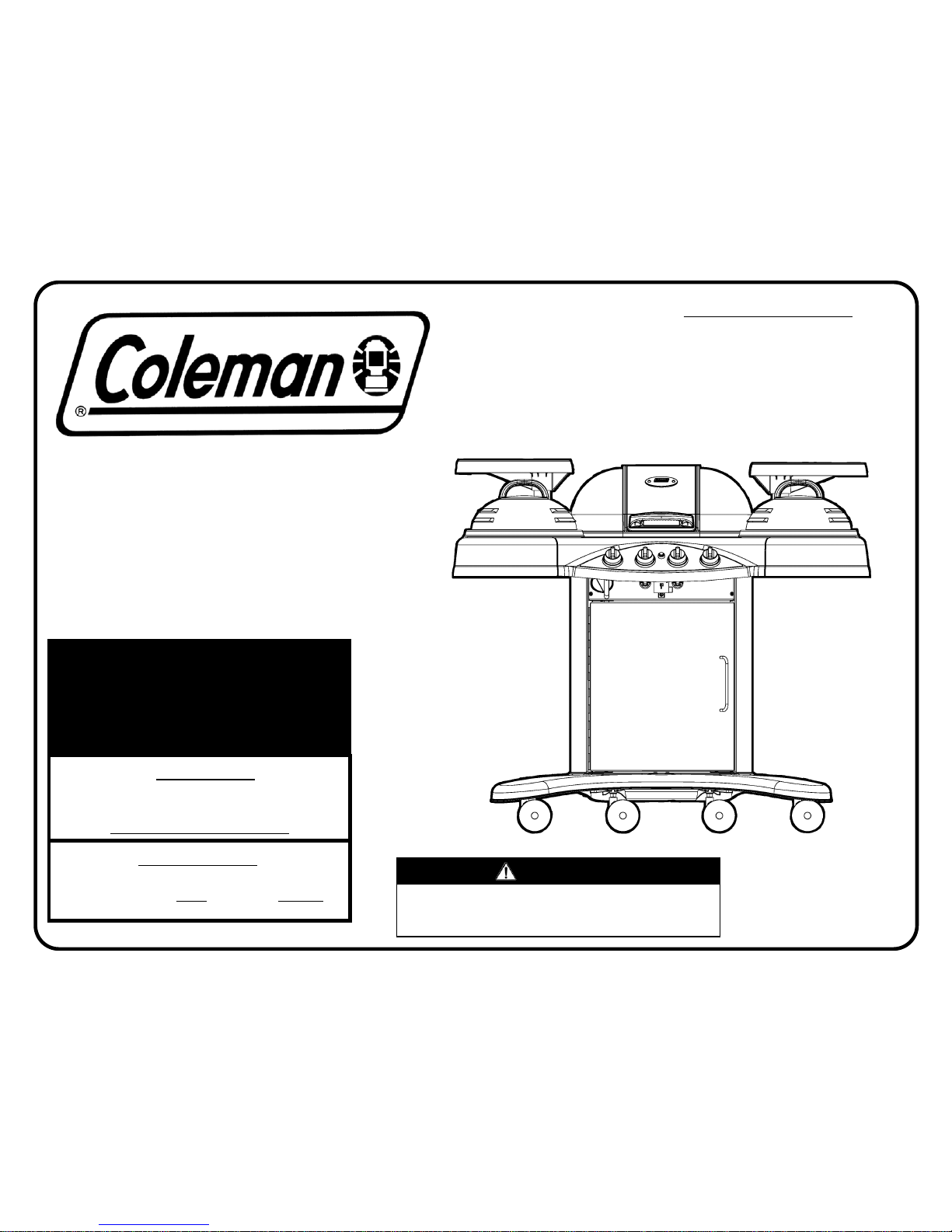
ASSEMBLY
INSTRUCTIONS FOR
9943 SERIES
GAS BARBECUE GRILL
9943-054 (04/26/02)
LOOK INSIDE FOR:
Easy Assembly Instructions
Repair Parts List
Safety, Maintenance
and Cleaning Tips
Coleman Company, Inc.
3600 N. Hydraulic
Wichita, KS 67219
Internet site:
www.coleman.com
1-800-356-3612
TDD: 316-832-8707
9-Volt
Battery
Included
LP Tank
Sold
Separately
WARNING:
THE EDGES OF SHEET METAL PARTS CAN CAUSE INJURY
IF NOT HANDLED WITH CARE
.
USE EXTREME CAUTION!
IMPORTANT!
TO ENSURE PROPER GAS FLOW, BURNER
CONTROL VALVES MUST
BE “OFF” BEFORE
OPENING THE GAS CYLINDER VALVE.
AASSSSEEMMBBLLEERR//IINNSSTTAALLLLEERR::
L
EAVE THESE INSTRUCTIONS WITH THE CONSUMER
.
CCOONNSSUUMMEERR//UUSSEERR::
R
EAD ALL THESE INSTRUCTIONS AND KEEP THEM IN A
SAFE PLACE FOR FUTURE REFERENCE
.
WARNING
Combustion by-products produced when using this product contain
chemicals known to the State of California to cause cancer, birth
defects, or other reproductive harm.
Page 2
(Pg. 2)
ÖÖ
#2 Phillips Screwdriver
ÖÖ
3/8”, 7/16” and 11/16” Open End Wrenchs
ÖÖ
3/8” Square Drive Ratchet Wrench
ÖÖ
3/8” Square Drive Extension
ÖÖ
Electric or Cordless Screwdriver
ÖÖ
#2 Phillips driver bit
ÖÖ
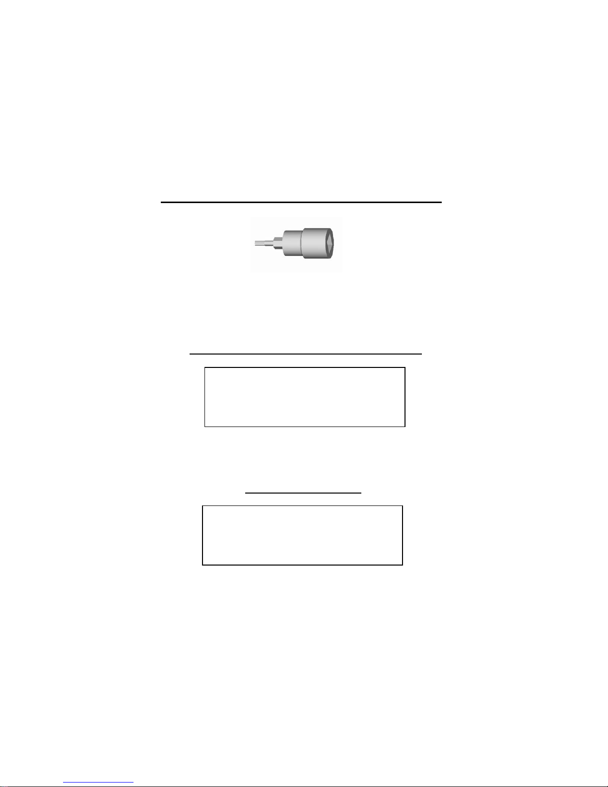
#T-20 6-Lobe Screwdriver
TORX BIT SOCKET INCLUDED
ADDITIONAL TOOLS NEEDED:
OPTIONAL TOOLS:
ÖÖ
#T-20, 3/8” Square Drive Torx Bit Socket
Page 3
(Pg. 3)
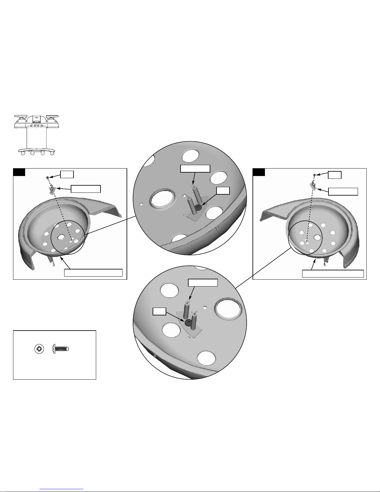
1-A
1-A. Assemble the Electrode to the Left Burner
Casting using one self-tapping screw (KE).
ÖÖ
Tighten all fasteners.
ÖÖ
Assemble the Electrode to the Left Burner Casting per illustration (1-A).
ÖÖ
Assemble the Electrode to the Right Burner Casting illustration (1-B).
Step
1
1-B
KE
Electrode
Electrode
Electrode
Right Burner Casting
Electrode
KE
Left Burner Casting
1-B. Assemble the Electrode to the Right Burner
Casting using one self-tapping screw (KE).
ÖÖ
Tighten all fasteners.
KE
KE
(KE)
#6-32 x 3/8 Self-tapping Screw
(2) Qty.
Hardware shown actual size
Page 4
(Pg. 4)
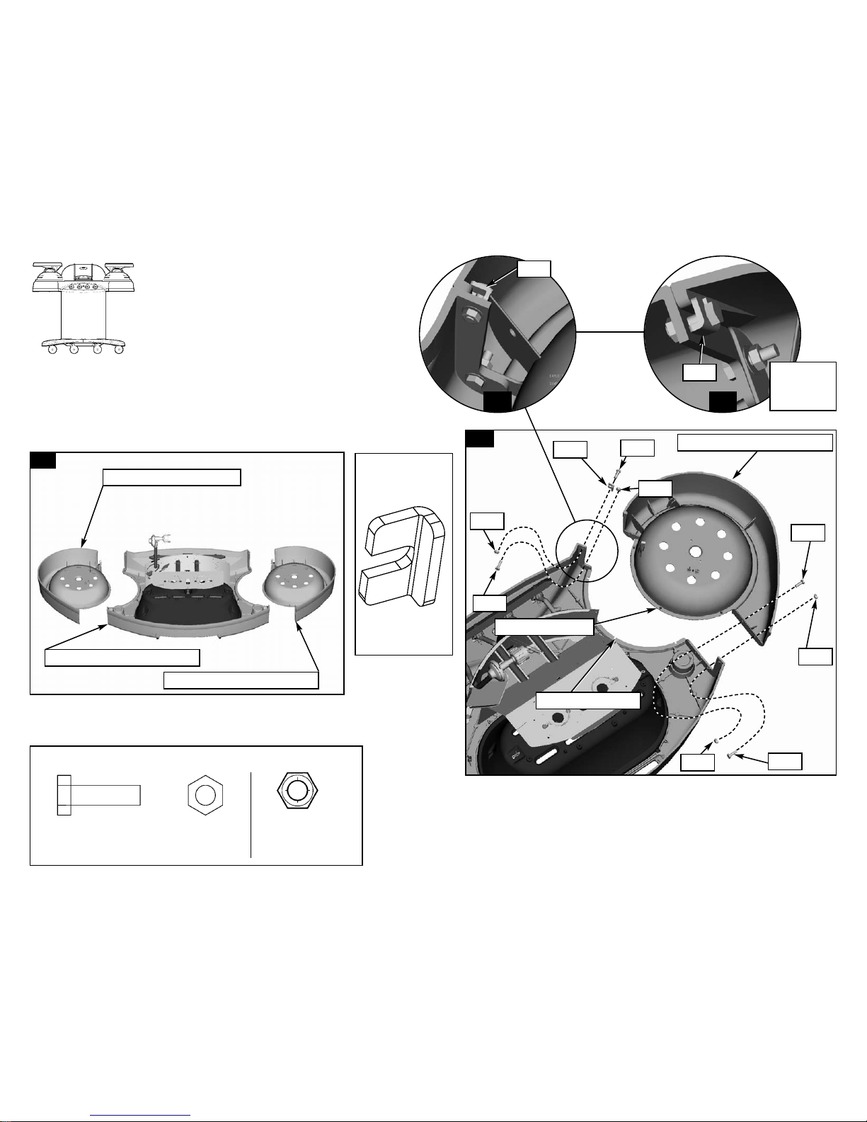
ÖÖ
NOTE: The grill is upside-down during this
assembly step.
ÖÖ
Assemble the CONSOLE CASTINGS.
ÖÖ
Use a large piece of cardboard or a ground
cloth to protect the painted finish on the
castings.
ÖÖ
Lay all three castings on a level surface with
the top (smooth) surface downward.
2-A
2-B.
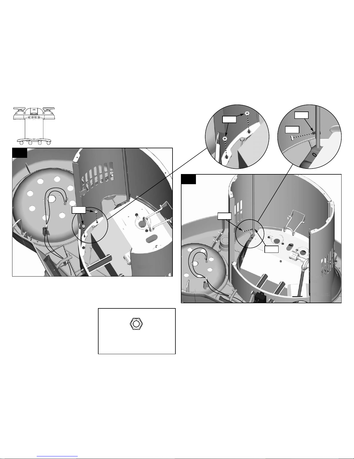
Assemble the Right Console Casting to the Center Console Casting. Three Alignment Pins
mate with three Alignment Holes in castings. Fasten with four SCREWS (MG) and four HEX
NUTS (BV) and one Clip (NH). See Detail 2-C and Detail 2-D for location of Clip (NH).
Tighten the fasteners.
ÖÖ
Repeat Step 2-B to assemble the Left Console Casting to the Center Console Casting.
2-A. Lay all three castings on a level surface with the smooth
(top) surface downward.
2-B
Right Console Casting
Left Console Casting
Center Console Casting
Step
2
(MG)
1/4-20 x 7/8 Hex Head Cap Screw
(8) Qty.
Hardware shown actual size
Hardware
shown actual
size
(BV)
1/4-20 Hex Nut
(8) Qty.
(NH)
Clip
(2) Qty.
Right Console Casting
Alignment Pin
Alignment Hole
NH
MG
BV
NH
NH
BV
MG
MG
BV
MG
BV
Another
View of
Clip (NH)
2-C
2-D
Page 5
(Pg. 5)
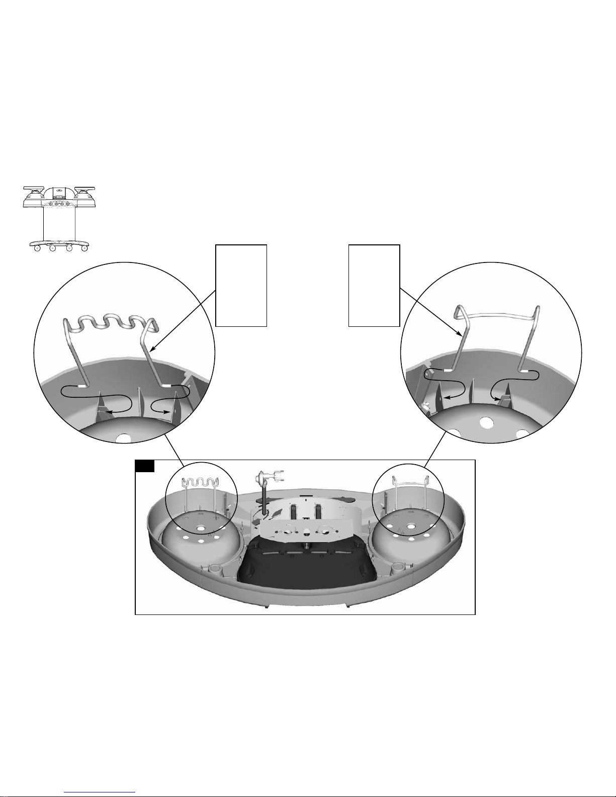
ÖÖ
NOTE: The grill is upside-down during this assembly step.
ÖÖ
Assemble the Tool Rack to the console.
ÖÖ
Assemble the Towel Rack to the console.
3-A
Step
3
Squeeze
the Towel
Rack to
slip into
the
mounting
holes.
Squeeze
the Tool
Rack to
slip into
the
mounting
holes.
Page 6

(Pg. 6)
ÖÖ
NOTE: The grill is upside-down during this assembly step.
ÖÖ
Assemble the 9-VOLT BATTERY to the ELECTRODE MODULE.
ÖÖ
Attach two wires (27” long) from the ELECTRODE MODULE labeled LB1 and LB2 to the LEFT BURNER (thread thru wire clip).
ÖÖ
Attach two wires (27” long) from the ELECTRODE MODULE labeled RB1 and RB2 to the RIGHT BURNER.
ÖÖ
Verify that two wires are attached from the MAIN BURNER to the ELECTRODE MODULE labeled MB1 and MB2 (factory installed).
ÖÖ
Verify that two wires are attached from the IGNITER BUTTON to the ELECTRODE MODULE on the left side (factory installed).
Step
4
4-A
4-B
Left Burner
Right Burner
4-C
Right Burner
Electrode Wires
Left Burner
Electrode Wires
Main Burner
Electrode Wires
Igniter Button
Wires
NOTE: Wires are
factory installed to the
Electrode Module.
9-Volt Battery
ELECTRODE MODULE
Left Side
Caution: Insure that the
wires DO NOT touch hot
surfaces such as the grill
casting!
ELECTRODE
MODULE
ELECTRODE
MODULE
MB1
LB1
RB1
MB2
LB2
RB2
Thread Wires
through Wire
Clip
Thread Wires
through Wire
Clip
Page 7
(Pg. 7)
5-A 5-B
5-C
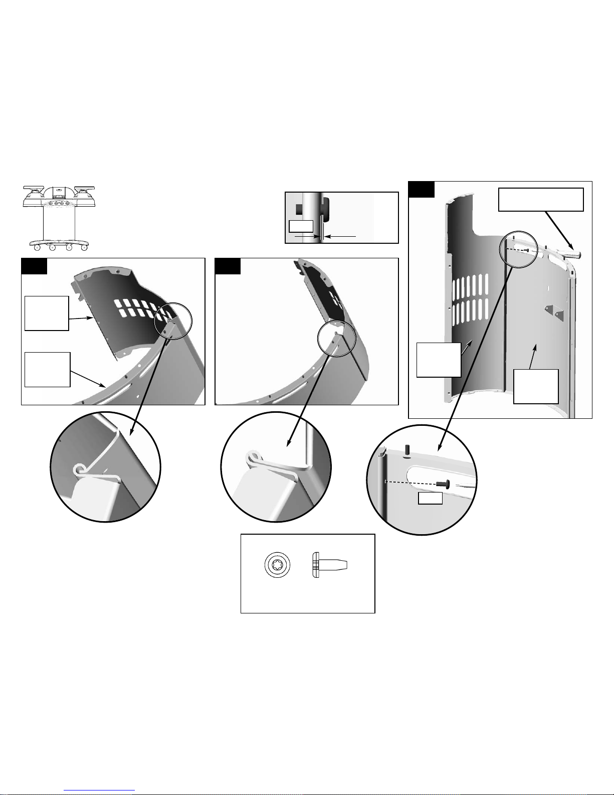
5-A. Assemble the PEDESTAL LEFT PANEL to the
PEDESTAL BACK PANEL.
ÖÖ
Insert the flat lip of the PEDESTAL LEFT PANEL
into the curled lip of the PEDESTAL BACK
PANEL, taking care to align the bolt holes.
ÖÖ
Assemble the PEDESTAL PANELS.
(DX)
#10-24 x 1/2 Self-tapping Screw
(2) Qty. Per Side Panel
Hardware shown actual size
5-C. LOOSELY fasten together with one SCREW (DX).
One at top only.
ÖÖ
NOTE: You will tighten this screw LATER, after the
panels are fastened to the grill console in Step 8-B
(this helps with alignment).
ÖÖ
Repeat Step 5 to assemble the RIGHT PANEL.
Pedestal
Left
Panel
Pedestal
Back
Panel
DX
Step
5
Use Tool Through
Opening
Stop (1) Turn
Before Tight
DX
Pedestal
Back
Panel
Pedestal
Left
Panel
Page 8
(Pg. 8)
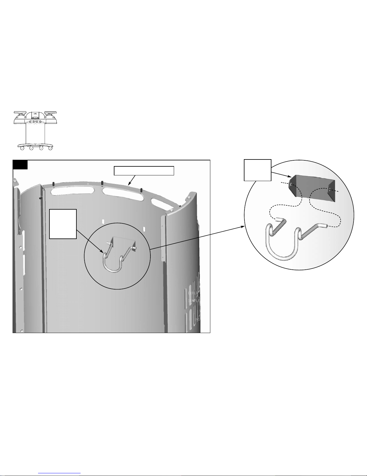
ÖÖ
Assemble PROPANE TANK RETAINER WIRE to the Pedestal Back Panel.
6-A
6-A. Assemble Propane Bottle Retainer Wire to the Pedestal Back Panel.
ÖÖ
Squeeze the Wire and insert into Bottle Retainer Bracket on Pedestal Back Panel.
Step
6
Propane
Bottle
Retainer
Wire
Bottle
Retainer
Bracket
Pedestal Back Panel
Page 9
(Pg. 9)
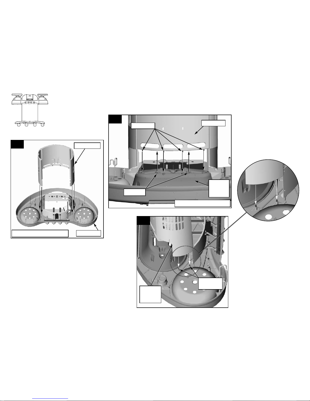
ÖÖ
NOTE: The grill is upside-down during this assembly step.
ÖÖ
Place the PEDESTAL onto the CONSOLE.
Step
7
7-A
7-B
7-C
7-A. Place the PEDESTAL onto the CONSOLE.
ÖÖ
Align the studs and pins with the assembly holes.
7-B. Align four studs with holes in
the Center Burner Casting.
ÖÖ
Align two pins (part of the
casting) with two holes in the
Pedestal.
7-C. Align two
studs with
holes in the
right pedestal
panel
(shown).
ÖÖ
Align two
studs with
holes in the
left pedestal
panel on the
opposite side
(not shown).
Pins (2)
View From Back Of Grill
View From Front Of Grill
Console
Pedestal
Studs (4)
Center
Burner
Casting
Pedestal
Right
Pedestal
Panel
Studs (2)
Per Side
Page 10
(Pg. 10)
ÖÖ
NOTE: The grill is upside-down during this assembly step.
ÖÖ
Fasten the PEDESTAL to the CONSOLE per Step (8-A).
ÖÖ
Tighten and secure the Pedestal Panel Fasteners per Step (8-B).
Step
8
8-A
8-B
EY
EY
EY
8-A. Assemble four HEX NUTS (EY),
one on each stud that protrudes up
from the casting into the pedestal
(they can be reached through the
front door opening).
ÖÖ
Assemble two on the right pedestal
panel (shown in Illustration 7-C and
8-A). and two on the left pedestal
panel (not shown).
ÖÖ
Tighten all fasteners.
8-B. Tighten the two screws (DX) loosely fastened earlier in Step 5-C.
Ö
Lock the two screws (DX) holding the PEDESTAL PANELS together with (2)
HEX NUTS (EY).
Ö
One HEX NUT (EY) assembles onto the right pedestal panel as shown. One
HEX NUT (EY) assembles onto the left pedestal panel.
Ö
Tighten all fasteners.
(EY)
#10-24 Hex Nut
(6) Qty.
Hardware shown actual size
DX
EY
DX
Page 11

(Pg. 11)
ÖÖ
NOTE: The grill is upside-down during this assembly step.
ÖÖ
Fasten the FRONT CONSOLE PANEL to the PEDESTAL.
Step
9
9-A. Assemble four SCREWS (CW) through the FRONT CONSOLE PANEL to the PEDESTAL.
ÖÖ
Tighten all fasteners.
9-A
(CW)
#10-24 x 3/8 Self-tapping Screw
(4) Qty.
Hardware shown actual size
CW
CW
CW
CW
Page 12

(Pg. 12)
10-A
10-B
ÖÖ
NOTE: The grill is upside-down during this assembly step.
ÖÖ
HINT: A second person may be helpful when aligning the Base Casting.
ÖÖ
Assemble the Base Casting to the Pedestal.
Step
10
(EY)
#10-24 Hex Nut
(9) Qty.
Hardware shown actual size
10-A. Carefully place the Base Casting onto the
Pedestal.
ÖÖ
The Base Casting has nine factory installed
studs. Carefully align the nine studs with the
nine matching holes in the Flange of the
Pedestal.
10-B. Assemble nine Hex Nuts (EY) to the nine
studs in the Base Casting.
ÖÖ
Tighten all fasteners.
Base Casting
Flange of Pedestal
with Nine Holes
EYEY
(9) Places
EY
EY
EY
Page 13

(Pg. 13)
11-A
11-B
11-A. Assemble locking casters to front of base.
ÖÖ
Assemble non-locking casters to back of base.
ÖÖ
Make sure hex bottoms out on base.
11-B. Fasten wheels tight against the Base Casting.
ÖÖ
Use an 11/16” open end wrench to tighten the Hex Collar against
the Base Casting.
ÖÖ
NOTE: The grill is upside-down during this assembly step.
ÖÖ
Assemble casters.
ÖÖ
Level and tighten the casters.
Hex Collar
Front
Step
11
Non-Locking Caster
Locking Caster
Base
Page 14

(Pg. 14)
12-A
ÖÖ
NOTE: Use a ground cloth to protect the paint finish during this step.
ÖÖ
Check that all fasteners are tightened before turning the grill Right-Side-Up.
ÖÖ
Carefully turn the grill Right-Side-Up.
Step
12
Protect with groundcloth
Protect with groundcloth
Control Panel this side.
Page 15

(Pg. 15)
ÖÖ
Complete Assembly of the Console to the Pedestal.
Step
13
13-A. Assemble four HEX NUTS (EY) onto the four studs that protrude through
the center burner casting.
ÖÖ
Tighten all fasteners.
EY
(EY)
#10-24 Hex Nut
(4) Qty.
Hardware shown actual size
13-A
View of Inside of Main Burner
Page 16

(Pg. 16)
ÖÖ
Assemble the BURNER to the RIGHT CONSOLE.
ÖÖ
Slip BURNER TUBE through RIGHT CONSOLE per detail 14-A.
ÖÖ
Align BURNER TUBE with VALVE TUBE per detail 14-B.
ÖÖ
Slip BURNER TUBE over VALVE TUBE per detail 14-C.
ÖÖ
Fasten BURNER in place per detail 14-D.
Step
14
11-D. Fasten the burner in place with two WINGNUTS (JD).
ÖÖ
Tighten all fasteners.
14-A
14-B
14-D
14-C
Burner
JD
JD
Burner Tube
Valve Tube
Right Console
(JD)
#10-24 Stamped Wing Nut
(2) Qty.
Hardware shown actual size
Caution: Assemble the
wires BELOW the burner
tubes!
Page 17

(Pg. 17)
ÖÖ
Assemble the BURNER to the LEFT CONSOLE.
ÖÖ
Slip BURNER TUBE through LEFT CONSOLE per detail 15-A.
ÖÖ
Move the Flexible Fuel Hose downward to give clearance for inserting the burner tube.
ÖÖ
Slip BURNER TUBE over VALVE TUBE per detail 15-C. The Flexible Fuel Hose and Wiring
must be routed BELOW
the burner tube per detail 15-D.
ÖÖ
Fasten BURNER in place per detail 15-D.
Step
15
15-A
(JD)
#10-24 Stamped Wing Nut
(2) Qty.
Hardware shown actual size
15-B
15-D
15-C
Left Console
Left Burner
Flexible Fuel Hose
Burner Tube
JD
JD
15-D. Fasten the burner in place with two WINGNUTS (JD).
ÖÖ
Tighten all fasteners.
Valve Tube
Flexible
Fuel Hose
Caution: Assemble the
wires BELOW the burner
tubes!
TEST THE IGNITER:
A SPARK SHOULD APPEAR AT
ELECTRODE TIP
.
I
F THE SPARK DOES NOT
APPEAR
:
-CHECK THE WIRE
CONNECTIONS TO THE
MODULE
.
-CHECK PROPER
ASSEMBLY OF FRESH
9-VOLT BATTERY.
Page 18

(Pg. 18)
16-A
16-A. Assemble the DOOR LATCH with two SCREWS (CW).
NOTE: You may have to adjust door latch to insure proper
alignment of door latch post. Refer to Step 18-B.
ÖÖ
Assemble the DOOR LATCH to the PEDESTAL.
Step
16
KE
Door Latch
KE
(KE)
#6-32 x 3/8 Self-tapping Screw
(2) Qty.
Hardware shown actual size
Page 19

(Pg. 19)
17-A
17-A. Attach the DOOR HANDLE to the DOOR with two SCREWS (FZ).
17-B
ÖÖ
Assemble the DOOR HANDLE to the DOOR.
ÖÖ
Assemble the DOOR LATCH POST to the DOOR.
Step
17
(LF)
#8-32 x 1/2 Self-tapping Screw
(2) Qty.
Hardware shown actual size
17-B. Attach the DOOR LATCH POST to the DOOR with two SCREWS (CW).
(KE)
#6-32 x 3/8 Self-tapping Screw
(2) Qty.
Hardware shown actual size
KE
KE
LF
LF
Door Latch Post
Door Handle
Page 20

18-A
(Pg. 20)
ÖÖ
Assemble the DOOR to the PEDESTAL.
ÖÖ
Adjust the DOOR LATCH on the PEDESTAL for proper door closure.
Step
18
18-A. Attach the DOOR to the PEDESTAL with four SCREWS (GA).
(GA)
#10-24 x 3/8 Flat Head Screw
(4) Qty.
Hardware shown actual size
18-B. Adjust the DOOR LATCH on the PEDESTAL for proper
door closure.
ÖÖ
Tighten all fasteners.
Door Latch
GA
(4) Places
Door
Page 21

(Pg. 21)
19-B
ÖÖ
Assemble the MAIN BURNER LID.
ÖÖ
Adjust the DOOR LATCH on the PEDESTAL for proper door closure.
Step
19
19-A
19-A. Attach the MAIN BURNER LID with two clevis pins (HB).
ÖÖ
Lock the clevis pins in place with two hairpin cotters (IC).
19-B. Detail showing location of clevis pin (HB) and hairpin (IC).
IC
HB
IC
HB
IC
HB
(HB)
3/16 Dia x 1-3/16 LG Clevis Pin
(2) Qty.
Hardware shown actual size
(IC)
Hair Pin
(2) Qty.
Page 22

(Pg. 22)
ÖÖ
Assemble the WARMING RACK and SUPPORT WIRE into the middle burner lid.
ÖÖ
Note: Steps 20-A and 20-B are pre-assembled at the factory. Proceed to Step 20-C.
Step
20
20-A
20-B
20-C
20-D
Warming Rack
Support Wire
Left Hole in Lid
20-A. Insert the SUPPORT WIRE into the left end of the WARMING RACK.
20-C. Insert the WARMING RACK through the Left Hole in the lid (far
enough to clear the Right Hole), then slide the WARMING RACK
into the Right Hole of the lid.
ÖÖ
Center the Warming Rack in the lid.
20-D. Insert the SUPPORT WIRE into the Left Pivot.
ÖÖ
Squeeze the SUPPORT WIRE to fit into the Right Pivot.
20-B. Thread the SUPPORT WIRE through the right end of the WARMING RACK.
Right Pivot
Left Pivot
Page 23

(Pg. 23)
ÖÖ
Assemble the SIDE TRAYS to the grill.
Step
21
21-A
21-A. Insert one SIDE TRAY POST into the grill. Align the notch in the
collar with the grill casting. It should not rotate in the hole.
ÖÖ
Place the SIDE TRAY onto the POST. It can be rotated from the
forward position (above the burner) to a limited outward position
(away from the burner).
ÖÖ
Repeat Step 21-A for the left SIDE TRAY.
21-B. SIDE TRAYS installed.
Side Tray Post
Side Tray
Collar
21-B
Page 24

(Pg. 24)
ÖÖ
Place DRIP PAN, SIDE BURNER GRID, and ROUND GRILL CASTING onto the left grill per Fig 22-A.
ÖÖ
Place DRIP PAN, SIDE BURNER GRID, and ROUND GRIDDLE CASTING onto the right grill per Fig 22-A.
Step
22
22-A
Drip Pan
Side Burner Grid
Round Griddle Casting
Drip Pan
Side
Burner
Grid
Round Grill Casting
Align Side Burner Grid
Between Rivet Heads
on the Drip Pan
Page 25

(Pg. 25)
ÖÖ
Place one Heat Tent on the main burner casting.
ÖÖ
Place two D-GRILLS on the main burner casting.
Step
23
23-A
23-C
23-B
23-B. HEAT TENT installed.
23-C. D-GRILLS installed.
Heat Tent
D-Grill
Heat Tent
D-Grill
Page 26

(Pg. 26)
ÖÖ
Place two SIDE LIDS on the side burners.
Step
24
24-A 24-B
24-A. Place one SIDE LID on each side burner. 24-B. SIDE LIDS can also be placed onto the SIDE TRAYS.
SIDE LID SIDE LID
SIDE TRAY
SIDE LID
Page 27

(Pg. 27)
ÖÖ
Open the front access door to place two GREASE CUPS under the main burner.
ÖÖ
Place the GREASE CUPS into the two wire holders below the main burner. See illustrations 25-A and 25-B.
ÖÖ
Place the GREASE DRIP TRAY into the holder behind the main burner lid. See illustrations 25-C and 25-D.
Step
25
25-C
25-D
GREASE DRIP TRAY
REAR VIEW OF GRILL
REAR VIEW OF GRILL
25-C. Place the GREASE DRIP TRAY into the holder.
25-D. Detail showing correct installation of the GREASE DRIP TRAY.
25-A
25-B
25-A. Place the GREASE CUPS into the wire holders.
25-B. Detail showing correct installation of the GREASE CUPS.
Grease Cups
Wire Holders
FRONT VIEW WITH DOOR OPEN
FRONT VIEW WITH DOOR OPEN
Page 28

(Pg. 28)
ÖÖ
Assemble an LP CYLINDER to the Cylinder Caddy. See detail 26-A.
ÖÖ
Place the CYLINDER RETAINER WIRE over the Cylinder Collar. See detail 26-B.
ÖÖ
Attach the TYPE 1 fitting to the Fuel Valve Outlet per detail 26-C.
Step
26
26-A
26-B
26-C
26-A. Set LP CYLINDER in the cylinder caddy with
the outlet valve facing toward the front of the
grill.
26-B. Place the CYLINDER RETAINER WIRE over
the Cylinder Collar, by rotating the wire from the
upward positon over the cylinder collar.
26-C. Insert the TYPE 1 Nipple of the regulator into
the cylinder’s Fuel Valve Outlet as shown. Turn
the regulator hand wheel clockwise to tighten.
No tools are needed. The hand wheel will come
to a complete stop when the connection is
secure, and gas will not flow until a positive seal
is achieved.
Type 1 Nipple
Fuel Valve Outlet
WARNING: During assembly of
grill and when attaching or replacing the
L.P. gas cylinder, insure that the gas
supply hose is free of kinks and/or
damage and is at least 3” away from hot
surfaces such as the grill casting.
IMPORTANT!
TO ENSURE PROPER GAS FLOW, BURNER
CONTROL VALVES MUST
BE “OFF” BEFORE
OPENING THE GAS CYLINDER VALVE
.
Cylinder Retainer Wire
Cylinder Collar
LP Cylinder
Cylinder Caddy
Page 29

(Pg. 29)
REPAIR PARTS
Description
Side Tray/Post Kit
Lid Assembly - Side
Lid Assembly - Center
Griddle - Side
Burner
D-Grill-Center
Grid - Side
Drip Pan Assembly
Warming Rack
Electrode and 27” Wires
Tool Hook/Towel Hook
Grease Cup
Latch Post
Door Assembly
Door Handle
Bottle Retainer
Caster Set (4 pc)
Heat Tent
Drip Tray
Grill - side
Main Burner
Igniter Switch
Knob & Bezel Kit
Control Panel Overlay
Trim Ring
Electrode Module
20” Igniter Wire
Hose/Valve/Regulator
Misc. Parts Kit
D-Griddle-Center (sold sepertely)
Part #
9943-2701
9943-4101
9943-4201
9942A3181
9943A3201
9941-3161
9943-3151
9943-5301
9943-3181
9943-4851
9943-1421
9943-0461
9943-0821
9943-5601
9943-1721
9943-0901
9943-0411
9943-1151
9943-1161
9942-3161
9943-5341
9943-2801
9943-1501
9943-1951
9943-0601
9943-2601
9943-0921
9943-6101
9943-0351
9941-3181
Key123456789101112131415161718192021222324252627282930
Page 30

(Pg. 30)
REP
AIR PARTS
21
22
23
24
25
26
27
28
Page 31

(Pg. 31)
REPAIR PARTS
1
10
11
12
13
14
15
16
17
18
19
20
13
11
9
2
7
8
3
4
6
5
Page 32

(Pg. 32)
For WARRANTY, SERVICE and PARTS
Locate your model number and serial number on the label found on the inside of your grill door.
C
ARE AND
CC
LEANING OF
GG
RILL
PP
ARTS
Ö
BEFORE cleaning any part of the grill, allow the grill to cool down completely.
Ö
Clean the grill with warm soapy water and a soft cloth.
Ö
NEVER USE OVEN CLEANERS.
Ö
To protect the integrity of your grill against the effects of the environment, use a grill cover when the grill
is not in use.
Ö
Failure to comply with the owner’s USE & CARE MANUAL INSTRUCTIONS & ASSEMBLY INSTRUCTIONS
can void right of warranty.
Leak test gas supply connections outdoors as
indicated by arrows.
WARNING! The edges of sheet metal parts can
cause injury if not handled with care.
USE EXTREME CAUTION!
WARNING! WHEN LEAK TESTING:
DO NOT smoke.
DO NOT use fire to test for leaks.
DANGER:
NEVER store a spare LP gas supply cylinder under the
grill body nor inside grill enclosure to avoid the possibility
of an explosion. Refer to the Use and Care manual.
IMPORTANT:
Be sure to tighten up all hardware (screws, nuts, bolts,
etc.) at least once a year or each grilling season.
READ OWNER’S USE AND CARE MANUAL:
For proper filling and purging of the cylinder
For leak testing all gas supply connections
For correct grill lighting instructions
For use and storage of the grill and cylinder
BEFORE USING YOUR GRILL
COLEMAN GAS BARBECUE GRILL WARRANTY
C
ASTINGS
- L
IMITED LIFETIME
B
URNER
- L
IMITEDTEN
(10) Y
EARS
E
LECTRONIC IGNITION COMPONENTS
- L
IMITEDTHREE
(3) Y
EARS
C
OOKING SURFACES
- L
IMITED
(2)
YEARS
O
THER PARTS
- L
IMITED ONE
(1) Y
EAR
The Coleman Company, Inc. (“Coleman”) warrants that for the period that you own this product, it will be free from defects in
material and workmanship. This warranty applies to the following parts for the following time periods: the castings are
warranted for LIFETIME against burn through; the burner is warranted for ten (10) years; electronic ignition components are
warranted for three (3) years; cooking surfaces are warranted for two (2) years; and other parts are warranted for one (1) year,
except the propane cylinder and paint finish. We DO NOT WARRANT in any way the propane cylinder (see label on cylinder
for cylinder manufacturer’s warranty) or the paint finish of the product. Coleman, at its option, will repair or replace this product
or any component of the product found to be defective during the warranty period. Replacement will be made with a new or
remanufactured product or component. If the product is no longer available, replacement may be made with a similar product
of equal or greater value. This is your exclusive warranty.
This warranty is valid for the original retail purchaser from the date of initial retail purchase and is not transferable. Keep the
original sales receipt. Proof of purchase is required to obtain warranty performance. Coleman dealers, service centers, or
retail stores selling Coleman products do not have the right to alter, modify or any way change the terms and conditions of this
warranty.
This warranty does not cover normal wear of parts or damage resulting from any of the following: negligent use or misuse of
the product, use on improper voltage or current, use contrary to the operating instructions, disassembly, repair or alteration by
anyone other than Coleman or an authorized service center. Further, the warranty does not cover Acts of God, such as fire,
flood, hurricanes and tornadoes.
Coleman shall not be liable for any incidental or consequential damages caused by the breach of any express or implied
warranty. Except to the extent prohibited by applicable law, any implied warranty of merchantability or fitness for a particular
purpose is limited in duration to the duration of the above warranty. Some states, provinces or jurisdictions do not allow the
exclusion or limitation of incidental or consequential damages or limitations on how long an implied warranty lasts, so the
above limitations or exclusion may not apply to you. This warranty gives you specific legal rights, and you may also have other
rights that vary from state to state or province to province.
DO NOT RETURN THIS PRODUCT TO THE PLACE OF PURCHASE.
Take the product to an authorized Coleman service center. You can find the nearest authorized Coleman service center by
calling 1-800-356-3612. If a service center is not conveniently located, you may call the same number for instructions on
shipping the product to the Coleman Company, Inc. You may also call the same number if you have any questions concerning
this warranty.
NOT VALID IN MEXICO.
 Loading...