

Page 1

INSTALLATION INSTRUCTIONS FOR
MODEL 7330D3351 & 7330D3361 WALL THERMOSTAT
APPLICATION
These thermostats are designed to operate all R.V. Products
ceiling assemblies, which control the air conditioner 115
VAC circuits through 12 VDC relays.
Wiring is required between the thermostat and the ceiling
assembly. The thermostat wiring is field installed and must
be considered before wall paneling and ceiling panels are in
place. Wall thermostat controlled air conditioners are
normally OEM (Original Equipment Manufacturer) installed.
Wall thermostat controlled air conditioners may be installed
for aftermarket applications, with additional considerations
given to the thermostat wire routing.
The 7330D3351 thermostat may also operate any RV furnace
12 VDC control circuit not exceeding one amp. All
thermostats are equipped with a replaceable 2 amp fuse
located on the back of the thermostat body.
INSTALLATION INSTRUCTIONS
BE SURE ALL ELECTRICAL POWER HAS BEEN
DISCONNECTED FROM THE AIR CONDITIONER,
THE CEILING ASSEMBLY AND THE POWER
SUPPLY.
These instructions are provided for the proper mounting of
the thermostat itself. An Operation Chart and Terminal
Cross Reference Chart are provided to show thermostat
capabilities.
Wiring procedure is dependent upon the ceiling assembly to
be matched with this component, and is provided in the
ceiling assembly installation instructions.
Recreation Vehicle Products suggests the thermostat wiring
be minimum 18 gauge.
2. Do not install the thermostat where there are unusual
heating conditions; such as direct sunlight, heat
producing appliances (television, radio, wall lamp,
etc.) or a furnace or air conditioner supply register.
B. ROUTING THE THERMOSTAT
WIRE BUNDLE
A separate wire bundle to power the 12 VDC thermostat will
need to be routed between the thermostat and the power
supply. Both positive and negative must be brought up to the
thermostat.
If a 12 VDC furnace is also to be operated, additional wiring
will need to be routed and a definite furnace location defined.
See Figure 1.
1. Route the wire bundle between the thermostat and
the ceiling assembly. Allow an additional 6 inches
of length at both the thermostat and the ceiling
assembly. This will give the installer the required
slack necessary for wiring. See Figure 1.
2. Route the separate 2 wire thermostat bundle between
the thermostat and the power supply. Allow 6
inches of additional wiring on both ends. See
Figure 1.
3. If a 12 VDC furnace is to be operated, route a wire
bundle between the thermostat and the furnace.
Allow an additional 6 inches at both ends. See
Figure 1.
4. If stapling the wire bundle during the routing
process, be careful not to pierce the thermostat
wiring insulation.
C. ATTACHING THE WALL THERMOSTAT
A. THERMOSTAT LOCATION
This thermostat is a sensitive instrument. For accurate
temperature control and comfort, the following considerations
should be taken into account:
1. Locate the thermostat on an inside wall about five
feet above the floor. Pick a dry area where air
circulation is good. The thermostat should be
mounted within a reasonable distance from the
appliance the thermostat will control. This will
assure a more accurate temperature relationship
between the thermostat and the appliance the
thermostat will control.
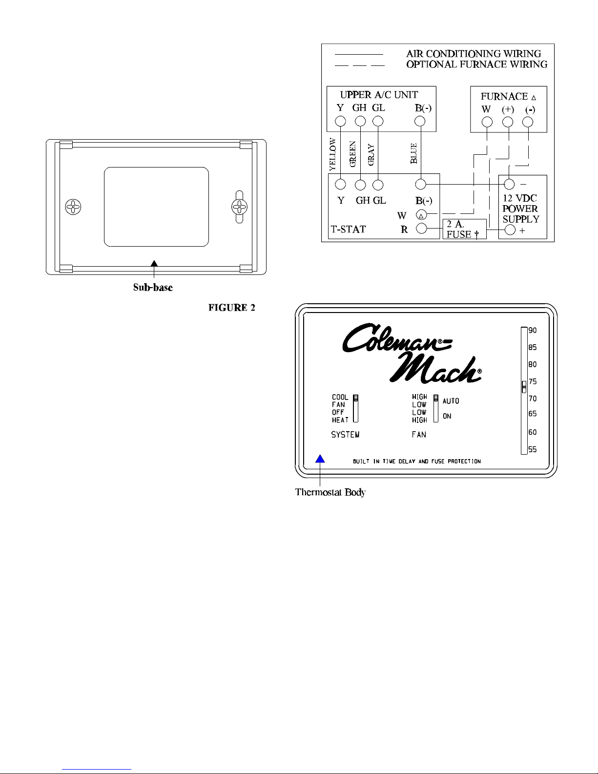
1. Separate the thermostat body from the sub-base by
gently pulling at the top and bottom. See Figure 2.
2. If this thermostat is a replacement thermostat for one
which has failed or no longer meets the needs of the
system: note the thermostat wiring on the back of the
old thermostat sub-base, and the system function
each wire was operating. This will save time and
trouble when rewiring the new thermostat. Before
removing the thermostat wiring from the old
thermostat, make sure the power supply to the
thermostat is disconnected.
Page 2
3. Attach the new thermostat sub-base to the wall at the
desired mounting location. Mount the sub-base to
the wall before wiring the thermostat.
† Suggested Fuse To Protect Wiring Leading To Thermostat
ª Not Found in “Cool Only” Applications
FIGURE 1
7330D3351
Heat/Cool Thermostat Shown
7330D3361
“Cool Only” Model Has No
Reference To Heat On Face Of
Thermostat
D. WIRING THE WALL THERMOSTAT
TO PREVENT POSSIBLE DAMAGE
TO THE EQUIPMENT OR PERSONAL
INJURY DUE TO ELECTRICAL SHOCK,
BE SURE THAT ALL ELECTRICAL
POWER TO THE THERMOSTAT HAS
BEEN DISCONNECTED BEFORE
BEGINNING WIRING PROCEDURE.
1. Strip the 12 volt supply wire ends approximately
3/8 of an inch.
2. Use the Wire Cross Reference Chart and connect
the appropriate conductor to the wire which
protrudes from the back of the thermostat (See
Figure 3). If this is a first time installation, note
the thermostat wire color for future reference in
order to properly connect the thermostat wiring
to the ceiling assembly.
3. Attach the negative and positive 12 volt power
supply wires to the appropriate wire on the
thermostat. It is important to identify the positive
and negative power supply wires before connecting
to insure proper thermostat operation. If this is a
replacement thermostat and there is no negative
12 VDC supply at the thermostat, a negative wire
from the power supply to the thermostat must be
added.
4. If a furnace system is to be operated from the
thermostat, strip and attach the furnace system wires.
2
Page 3

5. Gently push the excess thermostat wiring back into
the wall opening. Because the wall may have a
different temperature inside when compared to the
outside, fill the wall opening with a non-combustible
insulation. Insure that wires cannot contact
screws or sharp edges in the wall cavity.
6. Snap the thermostat body onto the base.
7. Turn the thermostat system switch to the “OFF”
position.
8. After the entire system (including the ceiling
assembly and roof top air conditioner) has been
properly installed, restore the electrical power to the
thermostat.
3
Page 4

OPERATION
The chart below shows the system functions with the 7330D3351 thermostat. After the entire air
conditioning system (and furnace system) is installed, check each position function. Disregard
references to heat functions when using the 7330D3361 “Cool Only” thermostat.
All cooling functions controlling to setpoint have a short
cycle protection time delay of 3 minutes. There will be no
delay if the cycle OFF time exceeds 3 minutes.
* There is no heat switch or furnace function available with
the 7330D3361 “Cool Only” thermostat.
RV Products
A Division of Airxcel, Inc.
P.O. Box 4020
Wichita, KS 67204
Page 5

1976D190 (5-01)
 Loading...