

Page 1
600 Watt WIND TURBINE
User’s Manual
Page 2

2
Congratulations on your Coleman® wind product purchase. This product is designed to the highest
technical specifications and standards. It will supply years of maintenance free use. Please read
these instructions thoroughly prior to installation, then store in a safe place for future reference. If at
any time you are unclear about this product, or require further assistance please do not hesitate to
contact our trained professionals operating the customer support line 1-888-478-6435 or email to
info@sunforceproducts.com
1. SAFETY
Your 600 Watt Wind Turbine is designed with your personal safety as the first priority. However,
there are still some inherent dangers involved with any electrical and/or mechanical equipment.
Safety must be the primary concern as you plan the location, installation and operation of the
turbine. Please read the following:
Important Safety Instructions
Please take the time to read through this manual prior to assembly.
1) Place this instruction manual in a safe place for reference.
2) Wait until a calm day to install or perform maintenance on your Turbine.
3) Listen to your Turbine. Should you hear any mechanical noise, maintenance
may be required. Please contact Sunforce Products Customer Service.
4) After installation re-adjust and tighten the screws and bolts.
5) Adhere to proper grounding techniques as established by the NEC.
6) Your Wind Turbine must be installed in accordance with this manual and local and
national building code. Incorrect installation may void your warranty.
7) Wind turbine blades spin at a potentially dangerous speed.
Never approach a turbine in motion.
8) Note wire size (gauge chart included) prior to wiring. Any under sizing of wire can be
potentially dangerous.
1.1 Mechanical Hazard
Rotating blades present the most serious mechanical hazard. The rotor blades are made of very
strong thermoplastic. At the tip, the blades may be moving at velocities over 15m/s. At this speed,
the tip of a blade is nearly invisible and can cause serious injury. Under no circumstances should
you install the turbine where a person could come in contact with moving rotor blades.
1.2 Electrical Hazard
The 600W Turbine is equipped with sophisticated electronics designed to provide protection from
electrical dangers. Please note that the inherent personal dangers from electrical current still
exist, therefore caution should always be used when connecting this and other electrical devices.
Page 3
3
Heat in a wiring system is often a result of too much current flowing through an undersized wire
or through a bad connection. Please consult wire guide table below.
Batteries can deliver a dangerous amount of current. If a short circuit occurs in the wiring from
the batteries, a fire can result. In order to avoid this threat, a properly sized fuse or circuit breaker
is required in the lines connecting to the battery.
Choosing your 600 Watt Wind Turbine’s location
Prior to the mounting of your 600 Watt Wind Turbine, you must carefully consider a location.
Things to consider when choosing your location:
A) Distance from any obstacles (trees, buildings, etc.) that will cause turbulence.
B) Distance from MPPT controller and battery bank.
C) Any local zoning restrictions.
D) Clearance of power lines.
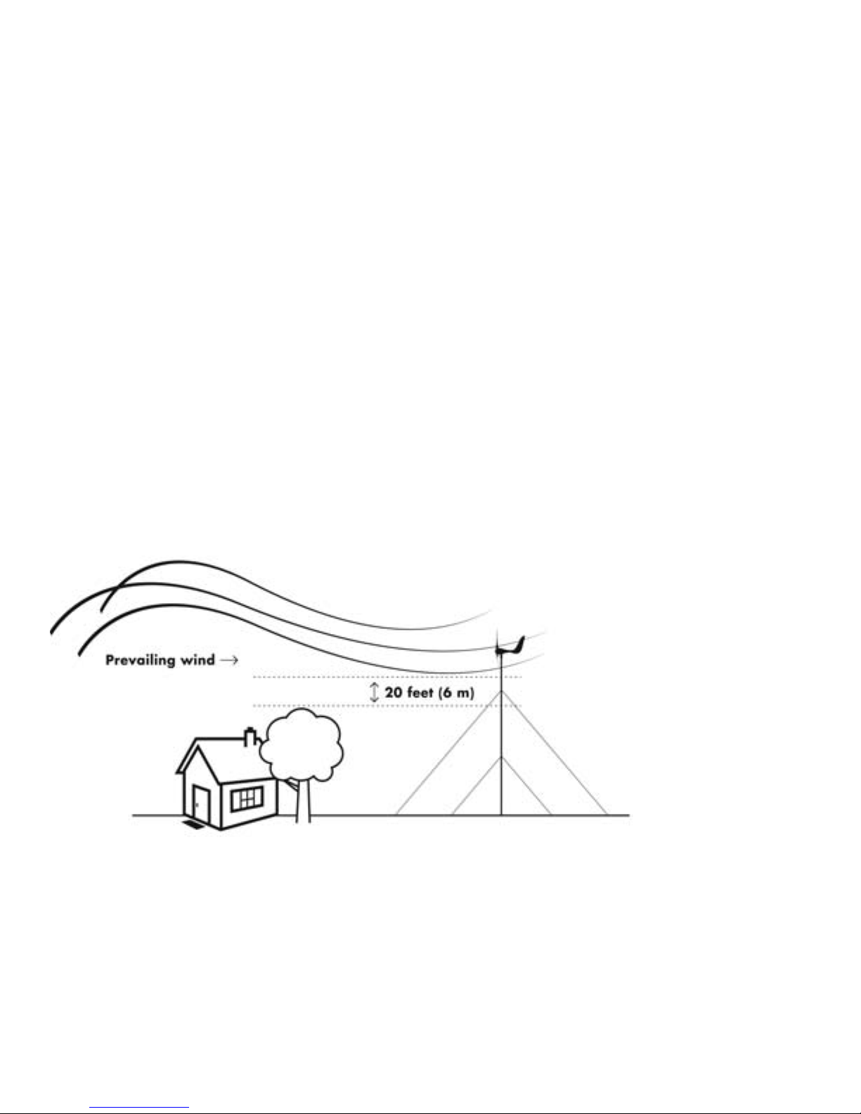
In general terms, the higher the tower the less obstruction to air flow, leading to a more efficient
chare capacity. The minimum recommended tower height is 30 ft or 20 ft above nearby
obstructions as shown below.
Page 4

4
2. MODEL AND SPECIFICATION TABLE
2.1 Specification Table
Model
600W Turbine
Related speed
12.5 m/s (41 ft/s)
Related power
600 W #
Voltage with MPPT
12 or 24 V ##
Rotor diameter
0.65 m (2.1 ft)
Cut-in wind speed
4.5 MPH
Survival wind speed
157 MPH
Number of Blades
3
Blade material
Fiber glass
Suggested battery capacity
>100 A/Hr
2.2 Performance specifications
The following power curve shows the performance you should expect from your wind turbine.
During smooth, steady wind speed, you can expect to see output resembling the curve
illustrated below. To convert between power and current, use the following formula:
POWER = VOLTAGE × AMPS
Page 5
5
3. Digital-controlled MPPT Wind Power Charger
Please see included Manual for your MPPT Charge Controller.
MCU fully digital-controlled MPPT wind power charger.
SEPIC conversion, large DC input voltage range.
Smart load management function, braking function.
Rated Output Power :
600W Max.
Battery Voltage Range:
12V or 24V DC
Input Voltage Range
5~75 Vrms
Charger Efficiency:
>87%
Battery Protection Voltage:
12V - 14.4V(Lead-acid batteries) or
15.8V(deep-cycle Battery)
24V - 28.8V (Lead-acid batteries)
or 30V (Deep-cycle batteries)
Rated Load Current:
35A Max.
Over-Speed Braking:
≦1400 rpm
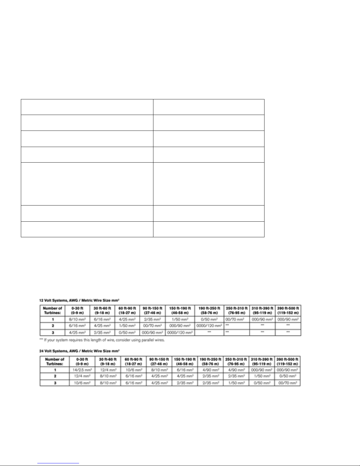
Caution: Please review the following wire gauge table to install the correct wire gauge. We
recommend these as the minimum wire sizes for optimal performance. Always use the largest
gauge wires that are practical and affordable. Local, state, and or national electrical codes take
precedence over these general recommendations.
System protection (see also included manual)
Your MPPT charge controller comes equipped with state of the art overcharge protection.
Temperature of the internal circuitry is moderated by an internal fan that is activated at 45
Page 6
6
C(110F). When the temperature of the MPPT exceeds 65C(150F) the MPPT will automatically
shut down and apply the braking system to your Wind Turbine to prevent damage.
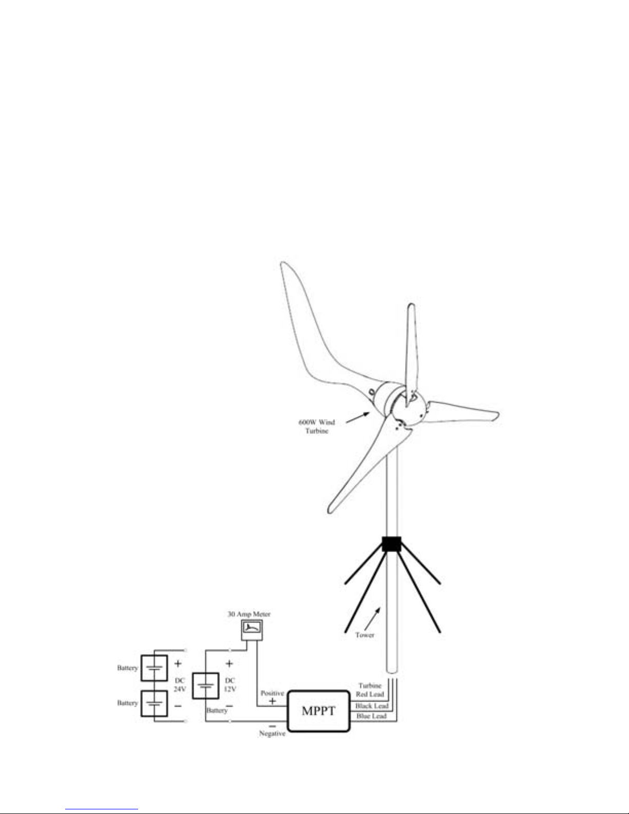
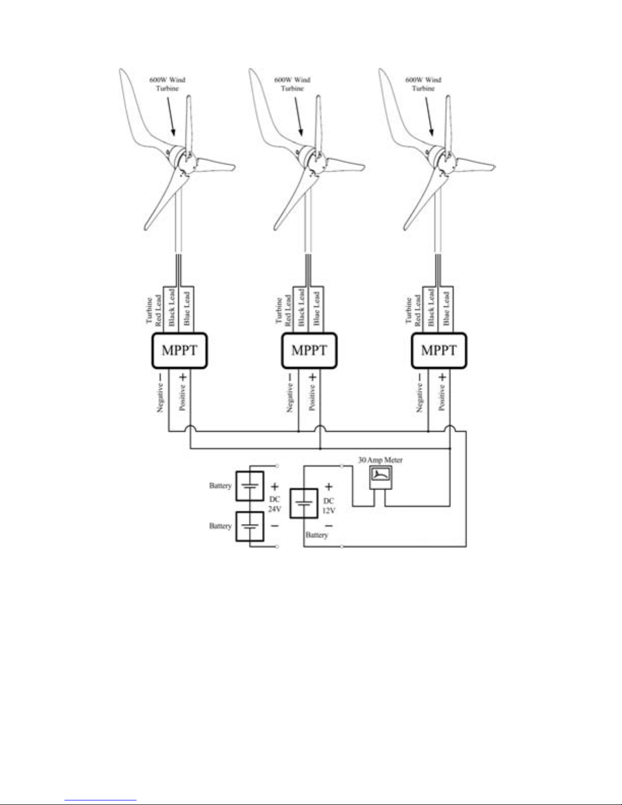
3.1 System wiring diagrams
There are multiple options to connect your Wind Turbine dependant on your power requirements
and available components.
Single Turbine installation:
Page 7
7
Multiple Turbine installation:
Page 8
8
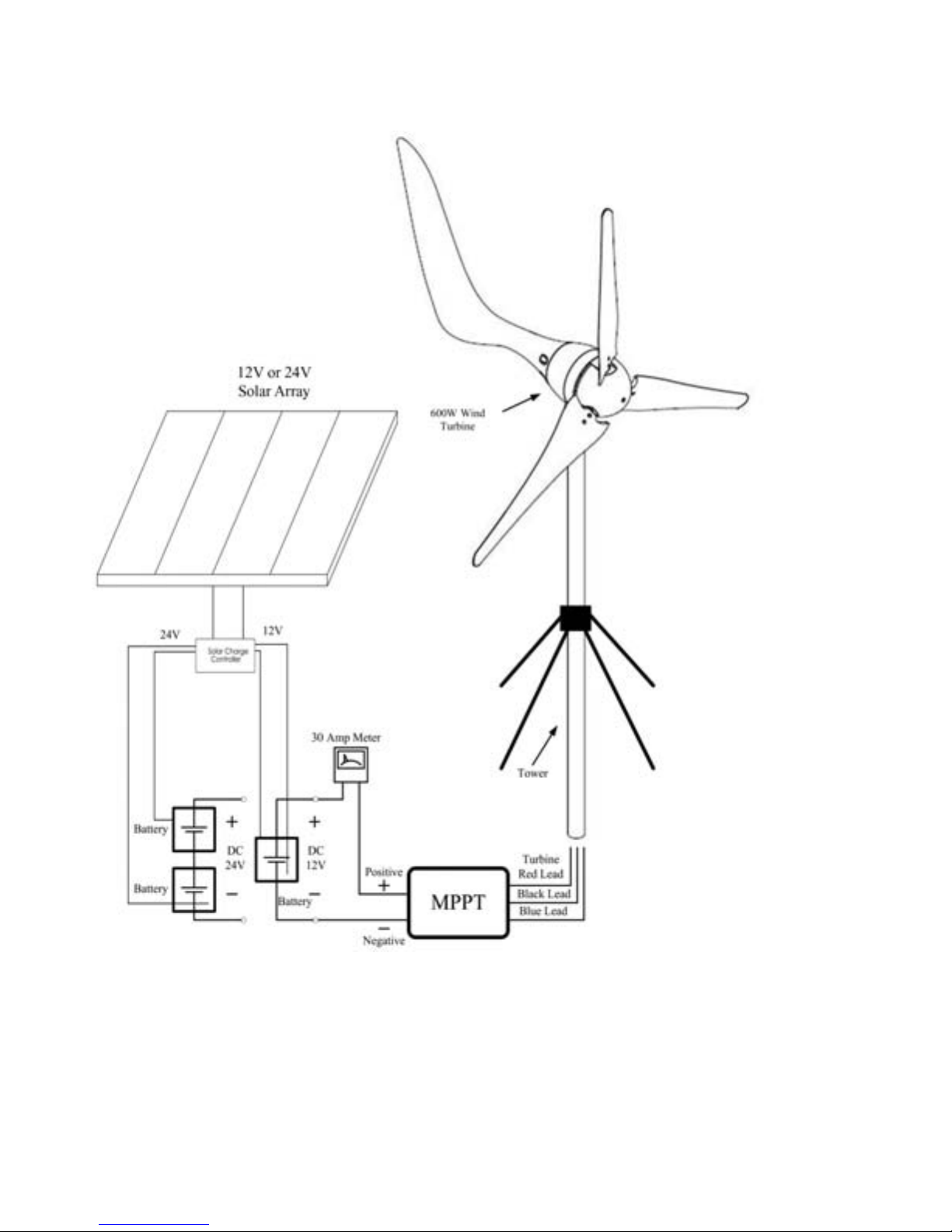
Hybrid Solar/Wind System
A typical “hybrid” system (Photovoltaic and Wind combined) is wired as follows. Whenever
feasible wire the turbine and solar panels to their own set of battery terminals.
Page 9
9
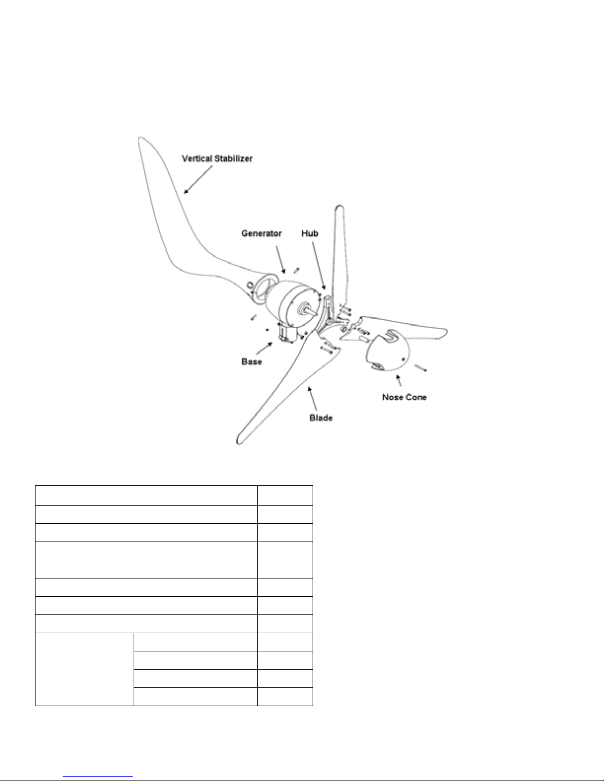
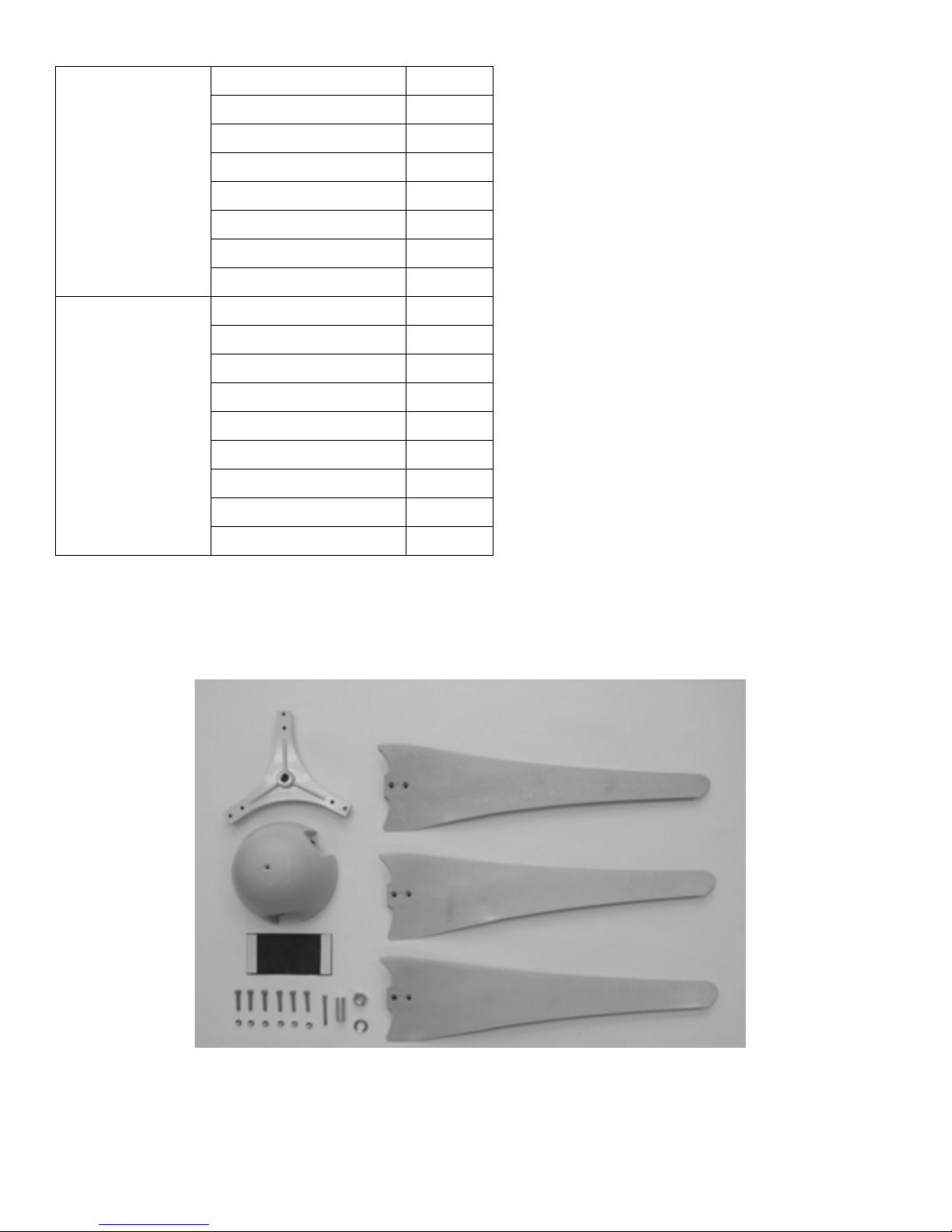
4. PACKAGE CONTENTS
Check the parts listed with the contents of the box and make sure that you have everything
needed for assembly.
Figure 1
Caution: The edges of the blades are sharp. Please handle with care.
Name
Quantity
Turbine
1
Blades
3
MPPT Charge Controller
1
Hub
1
Vertical Tail
1
Nose Cone
1
Amp Meter
1
Nut (M14xP2.0)
1
Hex Screw(M6xL30)
6
Nut (M6)
6
Hex Screw (M5xL12)
1
Page 10
10
Spring Washer (M14)
1
Stop Screw (M5xL20)
1
Hex Sleeve
1
Hex Key no.5
1
Hex Key No.3
1
Rubber Spacer
1
Hex Screw (M5xL20)
4
Screw Pack
Washer (M5)
4
Nut (M14xP2.0)
1
Hex Screw (M6xL30)
6
Nut (M6)
6
Hex Screw (M5xL12)
1
Spring Washer (M14)
1
Rubber Spacer
1
Hex Screw (M5xL20)
4
Washer (M5)
4
Replacement
Screw Pack
Stop Screw (M5xL20)
1
5. INSTALLATION PROCEDURE
Step 1: Open box to ensure all parts are present, remove the hub from the box.
Figure 2
Page 11
11
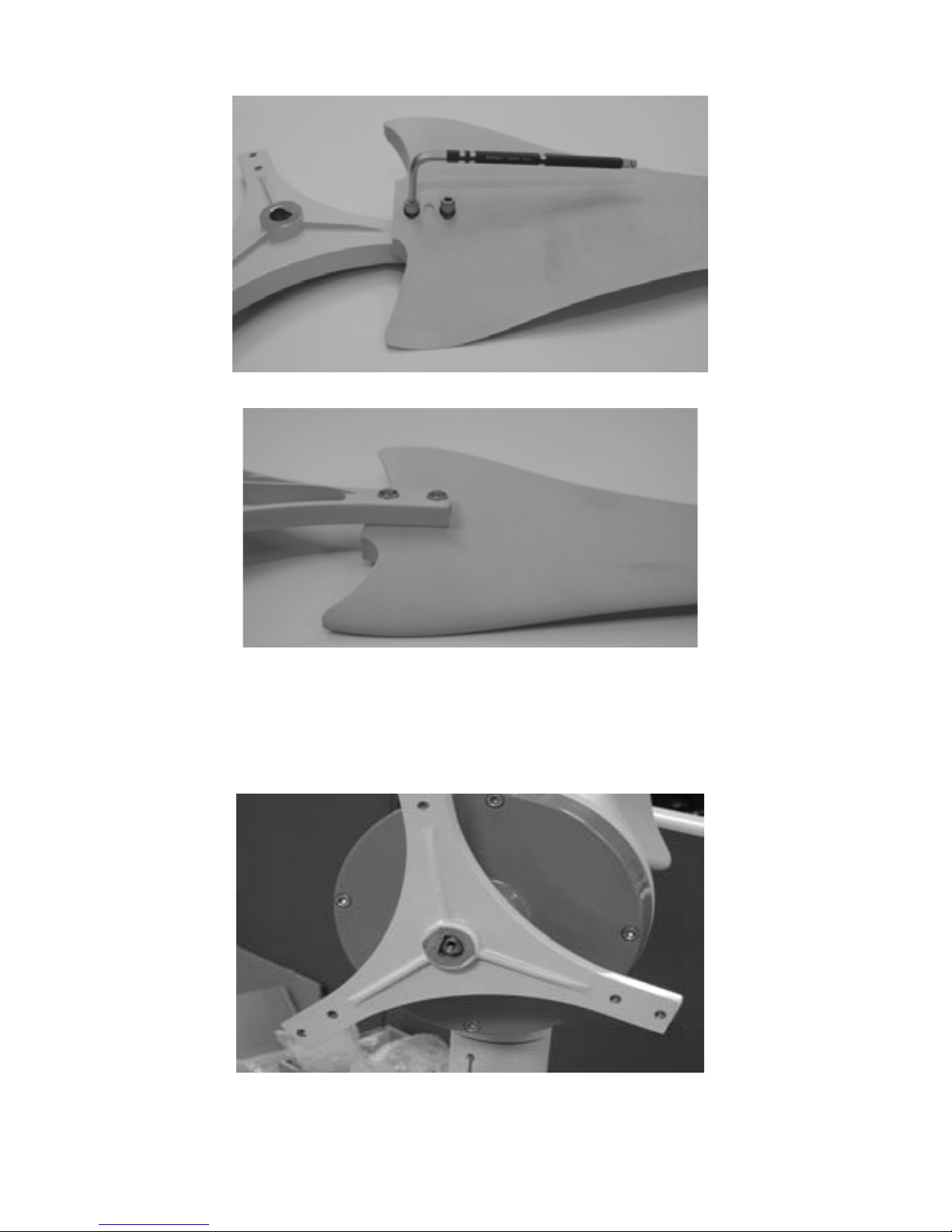
Step 2: Fasten the blades on the hub with the nuts.
Figure 3
Figure 4
Caution: Make sure that all of the bolts are secured with nuts.
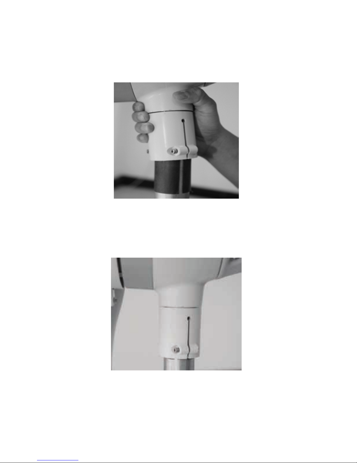
Step 3: How to install the hub.
Figure 5
Page 12
12
Adhesive strip should be wrapped around your Tower (tower not included) to
increase secure connection to the Yaw shaft.
Step 4: Remove wind turbine from the box and put the cables through the mast.
Figure 6
Step 5: To install the wind turbine to your chosen tower (tower not included) securely fasten the
bolt by using the hex wrench.
Figure 7
Page 13

13
Step 6: Install the hub on the wind turbine using the M14 nut and spring washer.
Figure 8 Figure 9
Caution: Make sure the nut is secured with the spring washer.
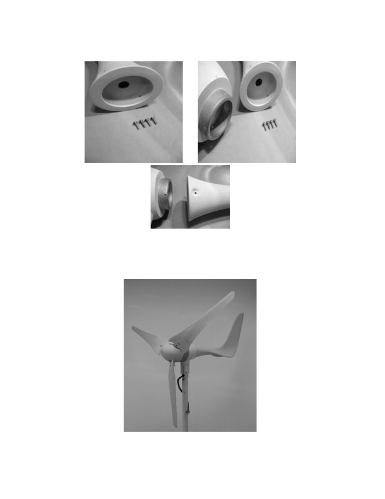
Step 7: Put the sleeve inside the nose cone and fasten the nose cone to the hub. Apply pressure
to the connections to ensure a secure fit.
Figure 10 Figure 11
Figure 12
Page 14
14
Step 8: Tail Fin assembly. Use the four supplied HEX screws, to firmly connect the Tail Fin to the
hub.
Figure 13
Step 9: Final product diagram.
Figure 14
Page 15

15
6. MAINTENANCE
Your 600 Watt Wind Turbine has been designed to run for long periods without requiring any
maintenance. Performance will be enhanced if you periodically inspect your system. Review the
following simple maintenance procedures and implement every six months.
Caution: Do not go near the wind turbine during operation.
Caution: The blades are sharp. Please handle with care.
• Check blades for superficial damage. Replace blades if damaged. It is important to not use
blades that are damaged, as you will lose overall balance, resulting in decrease in efficiency.
Should you notice damage to the blades you must replace all 3. The blades are balanced as
sets.
• Check the blade bolts and the hub nut for tightness.
• Check nosecone for cracks and tighten nuts.
• Wipe any excess dirt build-up from the blades.
• Check all electrical connections to make sure they are tight and free from corrosion.
• Check the voltage of your battery bank with a multi-meter and clean the terminals.
• We suggest replacing the blades every five years for optimal performance.
7. FAQS
How does the 600 Watt Wind Turbine control power and RPM in high winds?
Your Turbine’s operation will be halted to reduce the risk of damage due to overcharge and over
spin of the rotor blades. This process of braking is handled internally through your Turbines
electronics.
What is the maximum wind speed the 600 Watt Wind Turbine will survive and do I need to
take it down in a storm?
Your wind turbine is designed to operate in most climatic conditions. Should you expect or
experience winds of 150MPH upwards, please turn off the MPPT controller which will manually
apply the braking system to protect from any over spin. Once the Turbine has stopped, it is
possible to lay down the Tower to offer further protection.
How long will the bearings or other wearing parts last?
According to engineering calculations, the bearings should have a 10-year life span in 12 mph (6
m/s) average wind speed sites. Bearing life will vary from one application to another; however,
you should expect at least a five-year performance in adverse conditions and 10 years in normal
conditions.
Page 16

16
Can the 600 Watt Wind Turbine be connected in reverse-polarity to the battery without
causing any damage?
Reverse polarity will cause damage to both your MPPT controller and battery if not quickly
remedied. Always double check any wiring to reduce the risk of reverse polarity. Your turbine is
equipped with polarity protection to reduce the risk of damage, but it is still possible to degrade
your wiring and cause damage to the overall system.
Will it hurt my 600 Watt Wind Turbine to short-circuit the output?
No, the 600 Watt Wind Turbine is designed to be short-circuited as a normal shutdown
procedure by a fuse. The function of the stop switch is to both disconnect the turbine from the
batteries as well as short-circuit the output of the turbine.
Where can I locate tubing to make a tower?
Your 600 Watt Wind Turbine is designed to make mounting as simple and straightforward as
possible. Should you not wish to purchase the custom tower kit feel free to utilize schedule 40
1.5 inch steel tubing. This should be available through your local hardware outlet.
What is the difference between copper and aluminum wire?
Generally aluminum wire is less conductive, so it must be bigger for the same amp load and
resistive losses as copper. The 600 Watt Wind Turbine uses copper or tinned copper for the yaw
wires.
What battery should I choose for my 600 Watt Wind Turbine?
There are multiple battery options in today’s market– flooded lead acid, absorbed Glass mat
(AGM), gel cell and NiCad. There is no definitive choice for your alternative energy needs.
Normally the choice of battery is determined by availability and pricing. Should you have
questions regarding batteries please consult a local battery supplier. Or view:
www.batterycouncil.org. The capacity of your battery bank is determined by your use. Below is a
good guideline.
• 12-volt systems – 400 Amp-hours
• 24-volt systems – 200 Amp-hours
Page 17
17
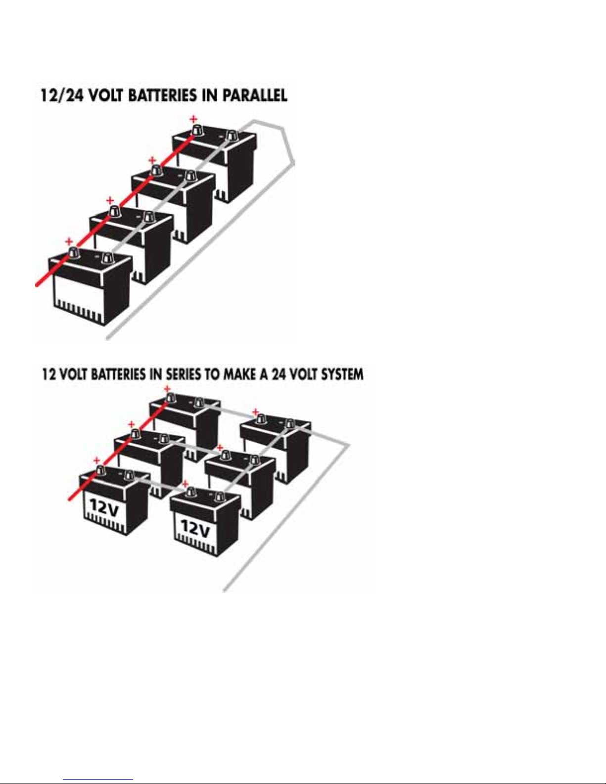
Possible Battery Configurations (suggested)
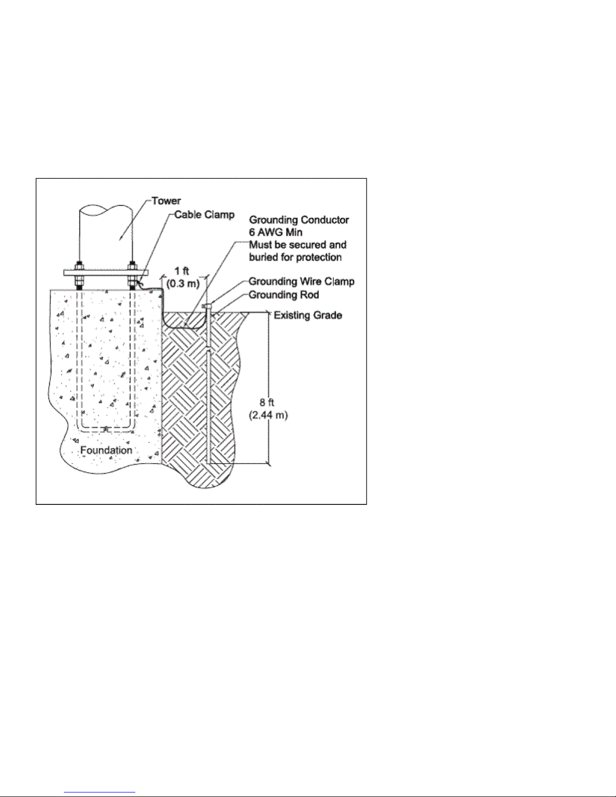
Is lightning protection necessary?
You should ground your 600 Watt Wind Turbine. Proper grounding (illustrated below) provides
protection to individuals and equipment by eliminating the possibility of dangerous voltage.
Remember, a steel tower is a conduit for lightning.
Every wind turbine and turbine tower needs to be grounded at the tower base
Page 18
18
even though the system may be grounded at the battery bank. Grounding the tower at its base
may help prevent shocks to persons touching the tower due to lightning or electrical faults.
Please take the time to review the National Electrical Code (NEC) and local
building and zoning regulations for complete requirements. Even in “Off Grid Systems”
There are multiple ways for tower grounding., The most common method is a copper clad steel
electrode(s) driven into the soil. Please view the following grounding diagram.
What effect does radio interference have on my 600 Watt Wind Turbine?
The internal circuitry of the 600 Watt Wind Turbine is shielded and filtered to prevent radio
interference, and has been tested to insure electro-magnetic compatibility.
What effect does my 600 Watt Wind Turbine have on radio transmissions?
The 600 Watt Wind Turbine normally does not affect radio transmitters. Care should be taken,
however, to route power lines from the 600 Watt Wind Turbine away from the power and antenna
lines of a radio transmitter. An old ham radio operator’s trick is to twist positive and negative
wires together to provide an even distribution of EMF noise across both wires, which serves to
cancel out the electrical noise created. This technique can be used on the 600 Watt Wind
Turbine power lines, on the radio’s power lines, and on transmission wires. Transmission lines
Page 19

19
should always be kept as far from power lines as is practically possible. Proper grounding of the
Turbine and other system components must also be observed.
Will it affect the regulation of my 600 Watt Wind Turbine to install an RF (radio frequency)
filter?
An RF filter should not affect the regulation of the Turbine, but any electronic devices placed in
line with the turbine must be rated for the proper current and voltage. It is best to place any line
filters on the power lines for the load device that requires it, and as close to the device as
possible.
Trouble shooting
You may require an extra person to assist with these tests.
1) Remove the blade/hub from the turbine. Replace the rotor hub nut on the rotor shaft.
2) Quickly spin the rotor shaft manually with your fingers while connecting and disconnecting
the red and black wires (turbine must not be connected to batteries).
3) With the red and black wires connected to each other, the shaft should be more difficult to
turn. When the wires are disconnected it should spin freely. Should this not be true please
contact supplier or Sunforce Products.
4) With your 600 Watt Wind Turbine connected to your battery bank, use an electric hand drill to
spin the rotor shaft.
5) Below 500 RPM, the rotor should spin freely without friction.
6) At 500 RPM and above, the Wind Turbine should be charging the battery. You should feel
resistance on the rotor shaft. If the shaft is not rotating, contact your turbine dealer or
Sunforce Products. Be aware your battery banks need to be under 12V or 24V for this testing
as the Turbine needs to read a charge.
WARRANTY
Sunforce Products warrants your product to be free from defects in material and/or workmanship for a period
of 5 years from original date of purchase. Warranty coverage is extended only to customer (original purchaser).
If product proves defective during warranty period, Sunforce Products, at its option will:
1. Replace wind turbine with new or a refurbished product.
2. Correct reported problem
Customers warranty continues to be valid on repaired or replaced product from original warranty date.
Restrictions
This warranty covers defects in manufacturing discovered while using the product as recommended by the
manufacturer. The warranty does not apply to a) equipments, materials, or supplies not manufactured by
Sunforce Products. b) Product that has been modified or altered other than by Sunforce Products or without
Page 20

20
prior Sunforce Products approval. c) Has been exposed to winds exceeding 157mph d) Windstorms, lightning
and Hail damage e) Repairs performed by other than authorized Sunforce Products support staff. f) All acts
of God; misuse, negligence or accidents. g) Tower foundation and wire h) has not been installed, operated,
repaired or maintained in accordance with the instructions supplied by manufacturer. Any service identified in
the above list or product is found not to have any defect in manufacturers’ workmanship or materials the
customer will be responsible for the costs of all repairs and expenses incurred by Sunforce Products.
Disclaimer
EXCEPT FOR THE EXPRESSED WARRANTY SET FORTH ABOVE, THE MANUFACTURER
DISCLAIMS ALL OTHER EXPRESSED AND IMPLIED WARRANTIES, INCLUDING THE
IMPLIED WARRANTIES OR FITNESS FOR A PARTICULAR PURPOSE, MERCHANTABILITY
AND NON-INFRINGEMENT. NO OTHER WARRANTY, EXPRESSED OR IMPLIED, WHETHER
OR NOT SIMILAR IN NATURE TO ANY OTHER WARRANTY PROVIDED HEREIN, SHALL
EXIST WITH RESPECT TO THE PRODUCT SOLD UNDER THE PROVISIONS OF THESE
TERMS AND CONDITIONS. THE MANUFACTURER EXPRESSLY DISCLAIMS ALL LIABILITY
FOR BODILY INJURIES OR DEATH THAT MAY OCCUR, DIRECTLY OR INDIRECTLY, BY USE
OF THE PRODUCT BY ANY PERSON. ALL OTHER WARRANTIES ARE EXPRESSLY WAIVED
BY THE CUSTOMER.
Warranty Claims & Return Policies
To be eligible for service under this warranty, customer must either contact manufacturer either through
written request or by telephone to submit a service request for the wind turbine covered by this warranty
within specified period (5 years from original date of purchase) and request a return authorization (RA)
number, This RA # must be issued before any product can be returned.
All notifications must include the following information:
a) Description of alleged defect
b) How the wind turbine was being used
c) Serial #
d) The original purchase date
e) Name, phone #, address of party requesting warranty
Within 2 to 3 business days Sunforce Products will provide the customer with an RA# and will direct customer
to location where the product is to be returned. Once an RA# has been issued the customer has 30 days to
return the product. Failure to deliver the product within the 30 days results in the RA# no longer being valid
and a new RA# must be issued. Manufacturer is under no obligation to accept any product that is returned to
them without a proper RA #.
Page 21

21
Limitation of Liability
UNDER NO CIRCUMSTANCES WILL THE MANUFACTURER OR ITS AFFILIATES OR
SUPPLIERS BE LIABLE OR RESPONSIBLE FOR ANY LOSS OF USE, INTERRUPTION OF
BUSINESS, LOST PROFITS, LOST DATA, OR INDIRECT, SPECIAL, INCIDENTAL, OR
CONSEQUENTIAL DAMAGES OF ANY KIND REGARDLESS OF THE FORM OF ACTION,
WHETHER IN CONTRACT, TORT (INCLUDING NEGLIGENCE), STRICT LIABILITY OR
OTHERWISE, RESULTING FROM THE DEFECT, REPAIR, REPLACEMENT, SHIPMENT OR
OTHERWISE, EVEN IF THE MANUFACTURER
OR ITS AFFILIATE OR SUPPLIER HAS BEEN ADVISED OF THE POSSIBILITY OF SUCH
DAMAGE. (Note: some states and provinces do not allow the exclusion or limitation of incidental or
consequential damages, so these limitations may not apply to you.) Neither the manufacturer nor its affiliates
or suppliers will be held liable or responsible for any damage or loss to any items or products connected to,
powered by or otherwise attached to the hardware. The total cumulative liability to Customer, from all causes
of action and all theories of liability, will be limited to and will not exceed the purchase price of the Product
paid by Customer. This warranty gives the Customer specific legal rights and the Customer may also have
other legal rights that vary from state to state or province to province.
Coleman® and are registered trademarks of The Coleman Company, Inc., used under license.
© 2010 The Coleman Company, Inc.
For more information or technical support
Contact: Les Produits Sunforce Products Inc. Montréal, Canada
1-888-478-6435 www.sunforceproducts.com info@sunforceproducts.com
Page 22

22
ÉOLIENNE 600 Watt
Notice D’utilisation
Page 23

23
Merci d'avoir choisi un produit Coleman. Tous les efforts ont été apportés pour assurer que ce produit est
conçu selon les spécifications et les normes techniques les plus strictes. Il devrait vous fournir des années
d'usage sans entretien. Veuillez lire avec soin ces instructions au complet avant l'installation et puis les
conserver en lieu sûr pour référence ultérieure. Si, en tout temps, vous n'êtes pas sûr au sujet de ce produit ou
avez besoin d'aide, veuillez contacter nos professionnels bien formés qui travaillent au service d'assistance
téléphonique au 1-888-478-6435 ou transmettez un courriel à info@sunforceproducts.com
1. SÉCURITÉ
Votre éolienne de 600 watts a été conçue en tenant compte de votre sécurité personnelle
comme étant de toute première priorité. Cependant, il existe toujours des dangers inhérents à
l'utilisation d'appareils électriques et mécaniques.
La sécurité doit être vos premiers soucis lorsque vous planifiez l'emplacement, l'installation et
l'exploitation de votre éolienne. Veuillez lire avec soin les directives suivantes.
Directives importantes de sécurité
Veuillez prendre le temps requis pour lire ce manuel avec soin avant de commencer l'assemblage
de l'équipement.
1) Conservez ce Manuel de l'utilisateur dans un endroit sûr pour référence ultérieure.
2) Attendez une journée calme pour installer votre turbine ou en effectuer l'entretien.
3) Si vous entendez un bruit mécanique, écoutez votre turbine. Vous devrez effectuer des essais
d'entretien ou consulter le Service à la clientèle de Sunforce.
4) Lorsque l'installation est terminée, ajustez et serrez les vis et les boulons.
5) Utilisez les techniques de mise à la terre établies par le NEC.
6) Votre éolienne doit être installée conformément aux directives de ce Manuel et des Codes du
bâtiment local et national. Une installation incorrecte peut annuler votre garantie.
7) Les pales de l'éolienne tournent à une vitesse potentiellement dangereuse; ce fait doit être
reconnu et vous devez toujours être extrêmement prudent. N'approchez jamais d'une éolienne
dont l'hélice est en mouvement.
8) Vérifiez le calibre des fils avant de commencer le câblage (tableau des calibres des fils inclus).
Les fils de calibre trop faible peuvent être potentiellement dangereux.
1.1 Danger mécanique
Les pales qui tournent créent le plus grand danger mécanique. Les pales de l'hélice sont
fabriquées d'un thermoplastique très robuste. Aux extrémités, les pales peuvent se déplacer à des
vitesses excédant 15 mètres à la seconde. À cette vitesse, l'extrémité de la pale est presqu'invisible
et peut causer des blessures graves. Il n'existe aucune exception où vous pouvez installer l'éolienne
là où une personne pourrait accidentellement entrer en contact avec les pales en mouvement.
1.2 Danger électrique
Page 24

24
L'éolienne 600W est équipée d'un système électronique sophistiqué conçu pour assurer une
protection contre les dangers électriques. Veuillez remarquer que des dangers personnels inhérents
causés par le courant électrique existent toujours et, de ce fait, il faut être extrêmement prudent lors
de la connexion de cet appareil électrique et de tout autre appareil similaire.
La chaleur dans le câblage d'un système résulte souvent d'un courant trop élevé circulant dans
des fils de calibre trop petit ou dans une mauvaise connexion.
Les batteries peuvent fournir un courant très élevé dangereux. Si un court-circuit survient dans le
câblage provenant des batteries, un incendie peut se déclencher. Pour prévenir ce risque, un fusible
ou un disjoncteur de calibre approprié doit être installé dans le circuit de branchement aux batteries.
Sélection de l'emplacement de votre éolienne 600W
Avant de procéder au montage de votre éolienne 600W, vous devez déterminer avec soin son
emplacement sur votre propriété.
Les éléments suivants doivent être pris en ligne de compte lors de la sélection de l'emplacement :
A) La distance de tous les obstacles pouvant causer de la turbulence comme les arbres, les
immeubles, etc.
B) La distance du contrôleur MPPT (Maximum Power Point Tracker – À conversion optimale
d'énergie) et du groupe de batteries
C) Toutes les restrictions de zonage locales
D) La distance de dégagement des lignes électriques
E)
En général, plus le mât de montage est haut, moins il y a d'obstruction à la circulation de l'air,
assurant ainsi une capacité de charge plus efficace. La hauteur minimale recommandée pour un mât
est de 9 m (30 pi) ou de 6 m (20 pi) au-dessus des obstructions environnantes tel qu'illustré
ci-dessous.
Page 25

25
2. TABLEAU DU MODÈLE ET DES SPÉCIFICATIONS
2.1 Tableau des spécifications
Modèle
Éolienne 600W
Vitesse associée
12,5 m/s (41 pi/s)
Puissance associée
600 W #
Tension avec MPPT
12 ou 24 V ##
Diamètre de l'hélice
0,65 m (2,1 pi)
Vitesse de fourniture
7,2 km/h (4.5 mi/h)
Vitesse de vent maximale (survie)
251 km/h (157 mi/h)
Nombre de pales
3
Matériau des pales
Fibre de verre
Capacité de batterie
recommandée
>100 A/h
# La puissance associée a été testée lors d'essais normalisés en soufflerie.
## Le changement d'une tension à l'autre peut être effectué avec le contrôleur MPPT.
2.2 Spécifications de la performance
La courbe suivante indique la performance que vous pouvez vous attendre d'obtenir de votre
éolienne. Lorsque le vent est régulier et constant, vous devriez vous attendre d'obtenir une puissance
de sortie près du haut de la courbe. Dans des conditions de vent turbulent, la puissance de sortie
pourrait chuter vers le bas de la courbe. Pour convertir la puissance en courant, utilisez la formule
suivante :
PUISSANCE (WATTS) = TENSION (VOLTS) × COURANT (AMPÈRES)
Page 26

26
3. Contrôleur de charge MPPT à contrôle numérique pour éolienne
Veuillez consulter le Manuel de l'utilisateur du contrôleur de charge MPPT inclus.
Contrôleur de charge MPPT à contrôle numérique total MCU (Multiple Control Unit – À contrôle
multiple) pour éolienne.
Conversion SEPIC (Single Ended Primary Inductance Converter – Convertisseur à inductance
primaire simple), large plage de tensions CC d'entrée.
Fonction de gestion intelligente de la charge, fonction de freinage.
Puissance de sortie nominale
600W Max.
Plage de tensions de la batterie
12 VCC ou 24 VCC
Plage de tensions d'entrée
5~75 V (efficace)
Efficacité du chargeur
>87 %
Tension de protection de la batterie
12V - 14,4 V (batteries au
plomb-acide) ou 15,8 V (batteries à
décharge poussée)
24V - 28,8 V (batteries au
plomb-acide) ou 30 V (batteries à
décharge poussée)
Courant de charge nominal
35 A max
Freinage à la vitesse d'emballement
≦ 1 400 tours/minute
Avertissement : Veuillez revoir le tableau des calibres des fils suivant pour vous assurer d'installer
du fil de calibre approprié. Nous recommandons de considérer ces valeurs comme les dimensions de
fil minimales pour une performance optimale.
Toujours utiliser les fils de plus gros calibre qui sont pratiques et rentables. Les codes électriques
locaux, d'États ou provinciaux et nationaux ont la priorité sur ces recommandations générales.
Page 27

27
Protection du système (Consultez aussi le manuel inclus)
Votre contrôleur de charge MPPT est équipé d'un circuit de protection contre la surcharge à la fine
pointe de la technologie.
La température des circuits internes est abaissée au moyen d'un ventilateur interne qui démarre à 45
°C (110 °F).
Lorsque la température du contrôleur de charge MPPT excède 65 °C (150 °F), celui-ci s'arrête
automatiquement et applique le freinage à votre éolienne pour prévenir les dommages.
3.1 Schémas de câblage du système
Plusieurs options existent pour effectuer le branchement de votre éolienne en fonction de vos
exigences en puissance et des composantes disponibles.
Page 28

28
Installation d'une seule éolienne :
Page 29

29
Installation de plusieurs éoliennes :
Page 30

30
Système hybride solaire/éolien
Un système « hybride » type (systèmes solaire et éolien combinés) est branché comme l'indique le
schéma ci-dessous.
Autant que possible, les fils de l'éolienne et des panneaux solaires devraient être branchés
séparément à leur propre ensemble de bornes de batterie.
Page 31

31
4. CONTENU DE L'EMBALLAGE
Comparez la liste des pièces au contenu de l'emballage et assurez-vous que tout ce dont vous avez
besoin pour l'assemblage est présent.
Figure 1
Danger : Les arêtes des pales sont vives. Soyez prudent et manipulez-les avec précaution.
Description
Quantité
Génératrice
1
Pale
3
Contrôleur MPPT
1
Moyeu
1
Empennage vertical
1
Coiffe
1
Ampèremètre
1
Écrou (M14xP2.0)
1
Vis (M6xL30)
6
Écrou (M6)
6
Boulon (M5xL12)
1
Page 32

32
Rondelle frein (M14)
1
Boulon (M5xL20)
1
Manchon hexagonal
1
Clé hexagonale n° 5
1
Clé hexagonale n° 3
1
Cale de caoutchouc
1
Vis hexagonale
(M5xL20)
4
Trousse de
quincaillerie
Rondelle (M5)
4
Écrou (M14xP2.0)
1
Vis hexagonale
(M6xL30)
6
Écrou (M6)
6
Vis hexagonale
(M5xL12)
1
Rondelle ressort (M14)
1
Cale de caoutchouc
1
Vis hexagonale
(M5xL20)
4
Rondelle (M5)
4
Trousse de
quincaillerie de
rechange
Vis d'arrêt (M5xL20)
1
5. PROCÉDURE POUR L'INSTALLATION
Étape 1 : Ouvrez l'emballage et assurez-vous que toutes les pièces sont présentes. Retirez le moyeu
de la boîte.
Page 33

33
Figure 2
Étape 2 : Retirez les pales de la boîte et fixez-les au moyeu utilisant les boulons et les écrous fournis.
Figure 3
Figure 4
Avertissement : Assurez-vous que tous les écrous soient bien serrés sur leurs boulons.
Page 34

34
Étape 3 : Comment installer le moyeu.
Figure 5
Une bande adhésive devrait être enroulée autour du mât (non inclus) pour assurer une
fixation plus sécuritaire du mécanisme de rotation horizontale.
Étape 4 : Retirez l'éolienne de la boîte et enfilez les câbles dans le mât.
Figure 6
Étape 5 : Pour installer votre éolienne sur le mât sélectionné (non inclus), serrez à fond le boulon au
moyen d'une clé hexagonale.
Page 35

35
Figure 7
Étape 6 : Installez le moyeu sur l'éolienne au moyen de l'écrou M14 et de la rondelle frein.
Figure 8 Figure 9
Avertissement : Assurez-vous que le boulon est bien sécurisé par la rondelle frein.
Étape 7 : Insérez la douille à l'intérieur de la coiffe et fixez la coiffe au moyeu. Appliquez une pression
sur les joints pour assurer un assemblage sécuritaire.
Page 36

36
Figure 10 Figure 11
Figure 12
Étape 8 : Assemblage de la dérive. Utilisez les quatre vis à tête hexagonale fournies pour fixer de
façon sécuritaire la dérive au corps de l'éolienne.
Page 37

37
Figure 13
Étape 9 : Schéma de l'assemblage final.
Figure 14
6. ENTRETIEN
Votre éolienne 600W a été conçue pour fonctionner pendant de longues périodes de temps sans
aucun entretien. Cependant, sa performance sera améliorée si vous inspectez régulièrement votre
système. Jetez un coup d'œil sur les procédures d'entretien simples suivantes et effectuer l'entretien
tous les six mois.
Danger : Ne vous approchez pas de l'éolienne lorsque qu'elle est en opération.
Danger : Les arêtes des pales sont vives. Soyez prudent lorsque vous les manipulez.
• Inspectez les pales pour détecter tout dommage superficiel. Remplacez les pales si elles sont
endommagées. Il est important de ne pas utiliser des pales endommagées puisque l'équilibre
global en sera affecté et que l'efficacité sera atténuée. Si des dommages existent, toutes les trois
pales doivent être remplacées. Les trois pales sont équilibrées comme un ensemble.
Page 38

38
• Assurez-vous que les boulons des pales et que l'écrou du moyeu soient bien serrés.
• Vérifiez la coiffe pour vous assurer qu'il n'existe pas de fissures et resserrez le boulon.
• Essuyez toute accumulation de saletés sur les pales.
• Vérifiez toutes les connexions électriques pour vous assurer qu'elles sont bien serrées et libres de
corrosion.
• Au moyen d'un multimètre, vérifiez la tension de votre groupe de batteries et nettoyez les bornes.
• Nous suggèrons de remplacer les pales tous les cinq ans pour obtenir une performance optimale.
7. FAQ
1) Comment l'éolienne 600W contrôle-t-elle la puissance et la vitesse de l'hélice par grand vent?
Le fonctionnement de votre éolienne sera interrompu pour réduire le risque de dommage causé
par la surcharge et l'emballement des pales de l'hélice. Ce processus de freinage est contrôlé par
les circuits électroniques internes de votre éolienne.
2) Quelle est la vitesse maximale de vent mon éolienne 600W peut-elle supporter sans dommage et
dois-je la descendre lorsqu'il y a tempête?
Votre éolienne est conçue pour fonctionner dans la plupart des conditions climatiques. Si des
vents de 240 km/h (150 mi/h) sont prévus ou existent déjà, veuillez commuter le contrôleur MPPT
hors circuit (OFF). Le contrôleur déclenchera alors le système de freinage pour protéger
l'éolienne de tout emballement. Lorsque l'éolienne est arrêtée, il est possible d'abaisser le mât
pour assurer une protection accrue.
3) Combien de temps dureront les roulements et les pièces affectées par l'usure?
Selon les calculs d'ingénierie, les roulements devraient avoir une vie utile de 10 ans sur les sites
où la vitesse de vent moyenne est de 6 m/s (12 mi/h). Cependant, la vie utile des roulements
variera d'une installation à l'autre. Vous devriez espérer une performance d'au moins cinq ans
dans des conditions défavorables et de dix ans dans des conditions normales.
4) L'éolienne 600W de peut-elle être branchée aux batteries en polarité inversée sans causer de
dommage?
Une polarité inversée endommagera le contrôleur MPPT et les batteries si on ne remédie pas
rapidement à cette situation. Revérifiez constamment tout câblage pour éliminer les risques
d'une polarité inversée. Votre éolienne est équipée d'un circuit de protection de polarité pour
réduire les risques de dommage mais il est toujours possible de dégrader votre câblage et
d'endommager le système au complet.
5) Mon éolienne 600W sera-t-elle endommagée si la sortie est court-circuitée?
Page 39

39
Non. L'éolienne 600W est conçue pour que sa sortie soit court-circuitée par un fusible lors de la
procédure normale de commutation hors circuit. La fonction du commutateur STOP (ARRÊT) est
de débrancher l'éolienne des batteries ainsi que de court-circuiter la sortie de l'éolienne.
6) Où puis-je trouver de la tuyauterie pour fabriquer un mât?
Votre éolienne 600W est conçue pour rendre son installation aussi simple et facile que possible.
Si vous ne désirez pas vous procurer l'ensemble de mât personnalisé, vous pouvez utiliser des
tuyaux d'acier de classe 40 d'un diamètre de 38 mm (1,5 po). Ces tuyaux devraient être
disponibles à votre quincaillerie locale.
7) Quelle est la différence entre le fil de cuivre et le fil d'aluminium?
Généralement, le fil d'aluminium est moins conducteur et, de ce fait, il doit être de plus gros
calibre pour le même courant de charge et les mêmes pertes par effet Joule que le fil de cuivre.
L'éolienne 600W utilise des fils de cuivre ou de cuivre étamé à sa sortie.
8) Quelle batterie dois-je utiliser avec mon éolienne 600W?
Sur le marché actuel, il existe toute une variété de batteries : plomb-acide ouvertes, à coussins
de verre saturés (AGM), sèches et NiCad. Il n'existe pas de choix définitif pour vos besoins
énergétiques. Généralement, le choix d'une batterie est déterminé à partir de la disponibilité et du
coût. Si vous avez des questions portant sur les batteries, veuillez consulter un fournisseur de
batteries local ou visitez le site Web www.batterycouncil.org. La capacité de votre groupe de
batteries est déterminée en fonction de votre consommation électrique. Une bonne suggestion
est offerte ci-dessous.
• Systèmes de 12 volts – 400 ampèreheures
• Systèmes de 24 volts – 200 ampèresheures
Page 40

40
Configurations possibles du groupe de batteries (suggérées)
9) Un système de protection contre la foudre est-il requis?
Vous devriez brancher le corps de votre éolienne 600W à la terre. Un branchement adéquat
(illustré ci-dessous) assure la protection des personnes et de l'équipement en éliminant les
risques et dangers des tensions dangereuses. Rappelez-vous qu'un mât d'acier est un
conducteur pour la foudre.
Chaque éolienne et chaque mât doivent être mis à la terre à la base du mât même si le système
est mis à la terre au groupe de batteries. La mise à la terre du mât à sa base peut prévenir les
chocs électriques causés par la foudre ou des défectuosités électriques aux personnes touchant
le mât.
Page 41

41
Veuillez prendre le temps de consulter les règlements du National Electrical Code (NEC) et les
codes du bâtiment et de zonage locaux pour vous familiariser avec toutes les exigences. Et ceci
s'applique même pour les « systèmes hors du réseau électrique ».
Il existe plusieurs méthodes de mettre le mât à la terre. La méthode la plus courante est d'utiliser
une électrode d'acier cuivré enfoncée dans le sol. Veuillez analyser le schéma de mis à la terre
ci-dessous.
10) Quel effet a la perturbation radioélectrique sur mon éolienne 600W?
Les circuits internes de la 600W sont blindés et filtrés pour prévenir la perturbation
radioélectrique et ont été testés pour assurer leur conformité électromagnétique.
11) Quel effet a mon éolienne 600W sur la transmission radio?
L'éolienne 600W n'affecte pas généralement les émetteurs radio. Cependant, vous devez
prendre soin d'éloigner les fils de l'éolienne 600W le plus possible des lignes d'alimentation et
de l'antenne d'un émetteur radio. Un vieux truc de radioamateur est de torsader les fils positif et
Page 42

42
négatif ensembles pour assurer une distribution égale des bruits électromagnétiques dans les
deux fils, cancellant ainsi le bruit électrique créé. Cette technique peut être utilisée sur les fils de
l'éolienne 600W, les fils d'alimentation et les lignes de transmission de la radio. Les lignes de
transmissions doivent toujours être maintenues le plus loin possible des lignes d'alimentation.
Une mise à la terre adéquate de l'éolienne et des autres composantes du système doit aussi être
assurée.
12) La régulation de mon éolienne 600W sera-t-elle affectée si j'installe un filtre FR (fréquence
radio)?
Un filtre FR ne devrait pas affecter la régulation de l'éolienne. Cependant, tout dispositif
électronique installé en série avec la sortie de l'éolienne devrait pouvoir soutenir nominalement le
courant et la tension générés par l'éolienne. Il est préférable de placer tout filtre de ligne sur les
fils d'alimentation de la charge qui le requièrent et le plus près possible de cette charge.
Dépannage
Vous pourriez avoir besoin de l'aide d'une autre personne pour effectuer ces tests.
1) Retirez l'ensemble pales/moyeu de l'éolienne. Remontez l'écrou du moyeu sur l'arbre du rotor.
2) Tournez rapidement l'arbre avec vos doigts tout en branchant ensemble et en débranchant les fils
rouge et noir (l'éolienne doit être débranchée des batteries).
3) Lorsque les fils rouge et noir sont branchés ensemble, l'arbre devrait être plus difficile à tourner.
Lorsque les fils sont débranchés, l'arbre devrait tourner librement. Si tel n'est pas le cas, veuillez
contacter votre fournisseur ou Sunforce Products.
4) Alors que votre éolienne 600W est branchée à votre groupe de batteries, utilisez une perceuse
électrique pour tourner l'arbre du rotor.
5) Sous 500 tours/minutes, le rotor devrait tourner sans résistance.
6) À 500 tours/minute et plus, l'éolienne devrait charger les batteries et vous devriez sentir la
résistance de l'arbre du rotor. Si l'arbre ne tourne pas, contactez votre fournisseur d'éolienne ou
Sunforce Products. Sachez que la tension de votre groupe de batteries doit se trouver sous 12 ou
24 volts pour ces tests puisque l'éolienne doit détecter qu'une charge s'effectue.
Garantie
Sunforce Products garantit que votre produit sera libre de défectuosités de matériaux et ou de fabrication
pendant une période de 5 ans débutant à la date de l'achat initiale. La garantie ne s'applique qu'à l'acheteur
initial. Si le produit s'avère défectueux au cours de la période de garantie, Sunforce Products, à sa discrétion
exclusive :
3. Remplacera votre éolienne défectueuse par une nouvelle éolienne ou une éolienne reconditionnée; ou
4. Corrigera la défectuosité rapportée.
Page 43

43
La validité de la garantie au client du produit réparé ou remplacé se continue à partir de la date d'application de
la garantie initiale.
Restrictions
Cette garantie couvre les défectuosités de fabrication découvertes lors de l'exploitation du produit utilisé selon
les recommandations du fabricant. La garantie ne s'applique pas a) aux équipements, matériaux ou accessoires
non fabriqués par Sunforce Products; b) aux produits qui ont été modifiés ou changés par une entité autre
que Sunforce Products ou sans l'autorisation écrite préalable de Sunforce Products; c) au produit qui a été
exposé à des vents excédant 251 km/h (157 mi/h); d) au produit endommagé par les vents violents, la foudre
ou la grêle; e) au produit réparé par une entité autre que le personnel de soutien autorisé de Sunforce Products;
f) au produit endommagé par forces majeures, utilisation incorrecte, négligence ou accidents; g) au produit
dont la fondation du mât et le câblage n'ont pas été installés, réparés, exploités ou maintenus en conformité
avec les recommandations du fabricant. Le client assumera la pleine responsabilité de tous les coûts de
réparation et des dépenses encourus par Sunforce Products si des services reliés à l'un des produits énumérés
ci-dessus ont été effectués sur des produits reconnus n'avoir aucune défectuosité de matériaux ou de
fabrication.
Avis de non-responsabilité
EXCEPTION FAITE DE LA GARANTIE EXPRESSE DÉTAILLÉE CI-DESSUS, LE FABRICANT
DÉCLINE TOUTES AUTRES GARANTIES EXPRESSES OU TACITES, INCLUANT LES
GARANTIES TACITES PORTANT SUR L'APTITUDE À L'EMPLOI, LA QUALITÉ MARCHANDE
ET LA NON-CONTREFAÇON DE BREVETS. AUCUNE AUTRE GARANTIE, EXPRESSE OU
TACITE, SIMILAIRE OU NON EN NATURE À TOUTE GARANTIE OFFERTE DANS LA
PRÉSENTE, N'EXISTERA RELATIVEMENT AU PRODUIT VENDU SOUS LES CONDITIONS
GÉNÉRALES DE LA PRÉSENTE. LE FABRICANT REJETTE EXPRESSÉMENT TOUTE
RESPONSABILITÉ POUR LES BLESSURES CORPORELLES OU MORTELLES RÉSULTANT,
DIRECTEMENT OU INDIRECTEMENT, DE L'UTILISATION DU PRODUIT PAR TOUTE
PERSONNE. LE CLIENT RENONCE EXPRESSÉMENT À TOUTES LES AUTRES GARANTIES.
Politiques sur les réclamations sous garantie et sur le retour de produit
Pour être éligible au service sous cette garantie, le client doit contacter le fabricant par écrit ou par téléphone
pour soumettre une demande de service pour l'éolienne couverte par cette garantie au cours de la période
spécifiée (5 ans à partir de la date de l'achat initial) et demander un numéro d'autorisation de retour (AR). Ce
numéro AR doit être émis avant le retour de tout produit.
Tous les avis doivent inclure les renseignements suivants :
f) Description de la défectuosité alléguée
g) Comment l'éolienne était utilisée
h) N° de série
Page 44

44
i) La date de l'achat initial
j) Nom, n° de téléphone et adresse de la personne demandant des services de garantie
Dans les 2 ou 3 jours ouvrables suivant la demande, Sunforce Products fournira un n° AR au client et lui
indiquera l'endroit où l'équipement doit être retourné. Lorsque le n° AR a été émis, le client aura 30 jours pour
retourner le produit. À défaut de retourner le produit durant cette période de 30 jours, le n° AR sera invalidé et
un nouveau n° AR devra être émis. Le fabricant n'est sous aucune obligation d'accepter tout produit retourné
sans un n° AR valide.
Limitations de la responsabilité
LE FABRICANT, SES AFFILIÉS OU SES FOURNISSEURS NE SERONT TENUS RESPONSABLES
DANS AUCUN CAS, DE TOUTE PERTE D'UTILISATION, D'INTERRUPTION D'ACTIVITÉ
COMMERCIALE, DE PERTES DE PROFITS, DE PERTE DE DONNÉES OU DES DOMMAGES
INDIRECTS, SPÉCIAUX OU ACCESSOIRES DE QUELQUE NATURE QU'ILS SOIENT
INDÉPENDAMMENT DE LA NATURE DE L'ACTE, SOIT PAR CONTRAT, PRÉJUDICE
(INCLUANT LA NÉGLIGENCE), RESPONSABILITÉ STRICTE OU AUTRE, RÉSULTANT DE LA
DÉFECTUOSITÉ, RÉPARATION, REMPLACEMENT, EXPÉDITION OU AUTRE, MÊME SI LE
FABRICANT, SES AFFILIÉS OU SES FOURNISSEURS ONT ÉTÉ AVISÉS DE LA POSSIBILITÉ DE
TELS DOMMAGES. (Remarque : certains États et provinces ne permettent pas l'exclusion ou la limitation
des dommages indirects ou accessoires et, de ce fait, ces limitations peuvent ne pas s'appliquer à vous.) Ni le
fabricant, ni ses affiliés, ni ses fournisseurs ne seront tenus responsables de tout dommage ou perte de tout
article ou produit branché à, alimenté par ou autrement raccordé au matériel. La responsabilité cumulative
totale envers le client découlant de toutes les causes d'acte et toutes les théories de responsabilités sera limitée
à, et n'excédera pas le prix d'achat payé par le client. La présente garantie accorde au client des droits
spécifiques et le client peut aussi avoir d'autres droits légaux pouvant varier d'un État à l'autre et d'une
province à l'autre.
ColemanMD et sont des marques déposées de The Coleman Company, Inc., utilisées sous licence.
© 2010 The Coleman Company, Inc.
Pour de plus amples renseignements ou de l'aide au niveau technique, contactez :
Les Produits Sunforce Products Inc., Montréal, QC, Canada
1-888-478-6435 www.sunforceproducts.com info@sunforceproducts.com
Page 45

45
TURBINA EÓLICA DE 600 VATIOS
Manual del Usario
Page 46

46
Felicitaciones por su compra Coleman. Hemos realizado nuestros mayores esfuerzos para asegurar que este
producto esté diseñado con los más altos estándares y especificaciones técnicas. Debería proveer de años de
uso libres de mantenimiento. Por favor, lea estas instrucciones cuidadosamente antes de instalar, luego
guárdelas en un lugar seguro para sus referencias futuras. Si en cualquier momento tiene dudas sobre este
producto, o requiere de asistencia, por favor, no dude en ponerse en contacto con nuestros profesionales
capacitados que lo atenderán en la línea de soporte al cliente, al número 1-888-478-6435, o escríbanos a
info@sunforceproducts.com
1. SEGURIDAD
Su Turbina Eólica de 600 Vatios está diseñada con su seguridad como nuestra prioridad principal.
Sin embargo, existen peligros inherentes relacionados con cualquier equipo eléctrico y/o mecánico.
La seguridad debe ser su principal preocupación al planear el lugar donde se colocará la turbina, su
instalación y su funcionamiento. Por favor, lea la siguiente información:
Instrucciones Importantes de Seguridad
Por favor, tómese el tiempo de leer completamente este manual antes de la instalación.
1) Colocar este manual de instrucciones en un lugar seguro para referencias.
2) Espere por un día calmo para instalar o realizar el mantenimiento de su turbina.
3) Escuche su turbina. Si escuchara cualquier sonido mecánico, podría ser necesario realizar el
mantenimiento. Por favor, póngase en contacto con el personal de Servicios al Cliente de
Sunforce Products.
4) Luego de la instalación, reajuste y apriete los tornillos y tuercas.
5) Siga las técnicas apropiadas de base, según lo que establece la NEC.
6) Su Turbina Eólica debe instalarse de acuerdo con lo indicado este manual y los códigos
locales y nacionales de construcción La instalación incorrecta puede anular la garantía.
7) Las palas de la turbina giran a una velocidad potencialmente peligrosa, y esto debe
respetarse. Nunca se acerque a una turbina en funcionamiento.
8) Note el tamaño del cable (cuadro de calibres incluido) antes de realizar el cableado. Cualquier
reducción del tamaño de los cables puede ser potencialmente peligrosa.
1.1 Riesgo Mecánico
Las paletas en rotación presentan un riesgo mecánico muy serio. Las paletas del rotor están hechas
de un termoplástico muy fuerte. En la punta, las paletas se pueden mover a velocidades superiores a
las 15m/s. A esta velocidad, la punta de la paleta es prácticamente invisible y puede causar daños
Page 47

47
serios. Bajo ninguna circunstancia se debe instalar la turbina en un lugar donde una persona podría
estar en contacto con las paletas en movimiento.
1.2 Riesgo Eléctrico
La turbina de 600 Vatios está equipada con elementos electrónicos sofisticados diseñados para
proveer de protección contra los peligros eléctricos. Por favor, note que aun así existen riesgos
personales inherentes de la corriente eléctrica, por lo tanto, se debe tener precaución al conectar
este y otros equipos eléctricos.
Con frecuencia se produce calor en los sistemas de cableado como resultado de la corriente que
fluye a través de un cable de menor tamaño del necesario o por una conexión errónea. Por favor,
consultar la siguiente tabla.
Las baterías puedes producir una cantidad peligrosa de corriente. Si ocurre un corto circuito en el
cableado de las baterías, se puede producir fuego. Para evitar este riesgo, se requiere un corta
fusibles o un corta circuitos en las líneas de conexión a la batería.
Elección del lugar de instalación de su Turbina Eólica de 600 Vatios
Antes de montar su Turbina Eólica de 600 Vatios, debe considerar cuidadosamente el lugar de
instalación.
Algunos puntos a tener en cuenta al pensar sobre el lugar de instalación:
A) Distancia de obstáculos que puedan causar turbulencia, árboles, edificios, etc.
B) Distancia de controladores MPPT y bancos de batería.
C) Las restricciones locales de zonas.
D) La liberación de los cableados de energía.
En términos generales, mientras más alta sea la torre, menor será la obstrucción del flujo de
aire, lo que llevará a una mayor capacidad de carga. La altura mínima recomendada para la
torre es de 30 pies a 20 pies por encima de las obstrucciones cercanas como se muestra a
continuación.
Page 48

48
2. TABLA DE MODELOS Y ESPECIFICACIONES
2.1 Tabla de especificaciones
Modelo
Turbina de 600 Vatios
Velocidad relacionada
12.5 m/s (41 pies/s)
Energía relacionada
600 Vatios #
Voltaje con MPPT
12 o 24 Voltios ##
Diámetro del rotor
0.65 m (2.1 pies)
Velocidad de viento de corte
4.5 MPH
Velocidad de viento de
supervivencia
157 MPH
Número de paletas
3
Material de las paletas
Fibra de vidrio
Capacidad sugerida de la batería
>100 A/Hr
Page 49

49
2.2 Especificaciones de desempeño
La siguiente curva de energía muestra el desempeño que debe esperar de su turbina eólica. Con
una velocidad suave y estable, puede esperar una producción similar a la curva que se ilustra a
continuación. Para convertir la energía y la corriente utilice la siguiente fórmula:
ENERGÍA = VOLTAJE x AMPS
3. Cargador de Energía MPPT controlado en forma digital
Por favor, ver el manual incluido para su controlador de carga MPPT.
Cargador de energía eólico MPPT, MCU controlado en forma digital.
Conversión SEPIC, gran voltaje de entrada de corriente directa.
Función de manejo inteligente de carga, función de corte.
Generación Rateada de Energía :
600 V Máx.
Rango de Voltaje de la Batería:
12V o 24V de Corriente Directa
Rango de Entrada de Voltaje:
5~75 Vrms
Eficacia del Cargador:
>87%
Voltaje de Protección de la Batería:
12V - 14.4V(baterías de plomo/ácido)
o 15.8V(baterías de ciclo profundo)
24V - 28.8V (baterías de plomo/ácido)
o 30V (baterías de ciclo profundo)
Carga Rateada de Corriente:
35A Máx.
Corte de la sobre-velocidad:
1400 rpm
Page 50

50
Precaución: Por favor revise la siguiente tabla de calibre de cableado para instalar el cableado con
el calibre correcto. Coleman recomienda estos como los tamaños mínimos de cables para un
funcionamiento óptimo. Siempre utilice los cables de mayor calibre que le sean prácticos y
accesibles. Los códigos eléctricos locales, estaduales y/o nacionales tienen precedencia sobre estas
recomendaciones generales.
Protección del sistema (ver también manual incluido)
Su controlador de carga MPPT viene equipado con protección contra sobrecarga de última
tecnología. La temperatura de los circuitos internos es moderada por un ventilador interno que se
activa a los 45ºC (110ºF).
Cuando la temperatura del MPPT excede los 65ºC (105ºF) su MPPT se apagará automáticamente y
se aplicará el sistema de corte a su Turbina Eólica para evitar daños.
3.1 Diagramas del sistema de cableado
Existen múltiples opciones para conectar su Turbina Eólica dependiendo de sus necesidades
energéticas y los componentes disponibles.
Page 51

51
Instalación de una sola turbina:
Page 52

52
Instalación múltiple:
Page 53

53
Sistema Solar/Eólico Híbrido:
Un típico sistema “híbrido” (Fotovoltaico y Eólico combinados) se instala como se muestra a
continuación. Cuando sea posible, cablear la turbina y los paneles solares en sus propios juegos de
terminales de baterías.
Page 54

54
4. CONTENIDO DEL PAQUETE
Revisar las partes listadas a continuación con los contenidos de la caja y asegúrese de que tiene
todos los elementos necesarios para el ensamblaje.
Figura 1
Precaución: Los bordes de las paletas son filosos. Por favor, manéjelos con cuidado.
Nombre
Cantida
d
Turbina
1
Page 55

55
Paletas
3
Controlador de Carga MPPT
1
Centro
1
Cola vertical
1
Cono de la nariz
1
Medidor de Amperes
1
Tuerca (M14xP2.0)
1
Tornillo
Hexagonal(M6xL30)
6
Tuerca (M6)
6
Tornillo Hexagonal
(M5xL12)
1
Arandela de Resorte
(M14)
1
Tornillo de Tope
(M5xL20)
1
Manga Hexagonal
1
Llave Hexagonal
no.5
1
Llave Hexagonal
No.3
1
Espaciador de Goma
1
Tornillo Hexagonal
(M5xL20)
4
Paquete de
tornillos
Arandela (M5)
4
Tuerca (M14xP2.0)
1
Tornillo Hexagonal
(M6xL30)
6
Tuerca (M6)
6
Tornillo Hexagonal
(M5xL12)
1
Arandela de Resorte
(M14)
1
Espaciador de Goma
1
Tornillo Hexagonal
(M5xL20)
4
Paquete de
Tornillos de
reemplazo
Arandela (M5)
4
Page 56

56
Tornillo de Tope
(M5xL20)
1
5. PROCEDIMIENTO DE INSTALACIÓN
Paso 1: Abrir la caja para asegurarse de que todas las piezas estén presentes, retirar el centro de la
caja.
Figura 2
Paso 2: Sacar las paletas de la caja y ajustarlas al centro con tuercas.
Figura 3
Page 57

57
Figura 4
Precaución: Asegurarse de que todos los tornillos están asegurados con tuercas.
Paso 3: Como instalar el centro.
Figura 5
Se debería colocar cinta adhesiva alrededor de la torre (no incluida) para incrementar la seguridad de
la conexión al mango giratorio.
Paso 4: Retirar la turbina de la caja y colocar los cables a través del mástil.
Page 58

58
Figura 6
Paso 5: Para instalar la turbina de viento a la torre elegida (no incluida) apriete las tuercas en forma
segura utilizando la llave hexagonal.
Figura 7
Paso 6: Instalar el centro en la turbina eólica utilizando un tornillo M14 y una arandela de resorte.
Page 59

59
Figura 8 Figura 9
Precaución: Asegurarse de que el tornillo está seguro con la arandela de resorte.
Paso 7: Colocar la manga dentro del cono de la nariz y asegurar el cono con el centro. Aplicar
presión a las conexiones para garantizar un calce seguro.
Figura 10 Figura 11
Figura 12
Paso 8: Ensamblaje de la cola: utilice los cuatro tornillos hexagonales que se proveen, para conectar
firmemente la cola al centro.
Page 60

60
Figura 13
Paso 9: Diagrama del producto final.
Figura 14
6. MANTENIMIENTO
Su Turbina Eólica de 600 Vatios se ha diseñado para funcionar durante largos periodos sin
necesidad de mantenimiento. El funcionamiento mejorará si inspecciona en forma periódica su
sistema. Revise los siguientes procedimientos simples de mantenimiento e impleméntelos cada seis
meses.
Page 61

61
Precaución: No se acerque a la turbina durante su funcionamiento.
Precaución: Las paletas son filosas, Por favor, manéjelas con cuidado.
• Revisar las paletas en búsqueda de daños superficiales. Reemplace las paletas si están
dañadas. Es importante no utilizar las paletas si están dañadas, ya que perderá el balance
general, lo que resultará en una disminución en la eficiencia. Si notara daños en las paletas,
debe reemplazar las tres. Las paletas están balanceadas en conjunto.
• Revisar el ajuste de los tornillos y tuercas de las paletas.
• Revisar el cono de la nariz en búsqueda de grietas y ajuste los tornillos.
• Sacuda cualquier exceso de tierra de las paletas.
• Revise todas las conexiones eléctricas para asegurarse de que están ajustadas y libres de
corrosión.
• Revise el voltaje de su banco de baterías con un multi-medidor y limpie los terminales.
• Coleman le sugiere que reemplace las paletas cada cinco años para un funcionamiento óptimo.
7. PREGUNTAS FRECUENTES (FAQS)
(1) ¿Cómo controla la energía y las RPM en vientos fuertes la Turbina Eólica de 600?
El funcionamiento de su turbina se detendrá para reducir el riesgo de daños debido a la
sobrecarga y los sobre-giros de las paletas rotadoras. Este proceso de corte se maneja en forma
interna a través de las turbinas electrónicas.
(2) ¿Cuál es la máxima velocidad del viento que resiste la Turbina Eólica de 600 Vatios, y
necesito desmontarlo en caso de tormenta?
Su turbina eólica está diseñada para funcionar en la mayoría de las condiciones climáticas. Si se
esperan o se experimentan vientos superiores a 150 MPH, por favor apagar el controlador MPPT
que a su vez aplicará en forma manual el sistema de corte para proteger de los sobre-giros. Una
vez que la turbina se haya apagado, es posible bajar la torre para mayor protección.
(3) ¿Cuánto durarán los rodamientos y otras partes desgastadles?
De acuerdo con los cálculos de ingeniería, los rodamientos deberían tener una vida útil de 10
años en lugares con velocidad de viento promedio de 12 mph (6m/s). La vida útil cariará de una
aplicación a otra; sin embargo, se deberían esperar por lo menos 5 años de desempeño en
condiciones adversas y 10 años en condiciones normales.
(4) ¿Se puede conectar la Turbina Eólica de 600 V en polaridad reversa a la batería sin causar
daños?
La polaridad reversa causará daños tanto a su controlador MPPT como a su batería si no se
Page 62

62
remedia inmediatamente. Siempre revise los cableados para reducir riesgos de polaridad reversa.
Su turbina está equipada con protección de polaridad para reducir el riesgo de daños, pero aún
así es posible que se degrade su cableado y que ocurran daños en el sistema en general.
(5) ¿Causará daños a mi Turbina Eólica de 600 V hacer corto circuito a la producción de
energía?
No, la Turbina Eólica de 600 V está diseñada para que se le realice un corto circuito como un
procedimiento normal de apagado por un fusible. La función del botón de apagado es la de
desconectar la turbina de las baterías así como de hacer un corto circuito en la producción de la
turbina.
(6) ¿Dónde puedo encontrar tubos para hacer una torre?
Su Turbina Eólica de 600 V está diseñada para hacer el montaje lo más sencillo y directo posible.
Si no quisiera comprar el paquete adaptado para la torre, siéntase libre de utilizar tubos cédula 40
de acero de 1,5 pulgadas. Este tubo debería estar disponible en su ferretería local.
(7) ¿Cuál es la diferencia entre cables de cobre y de aluminio?
Generalmente el cable de aluminio es menos conductor, así que debe ser mayor para lograr la
misma carga de amperes y la resistencia a la pérdida del cobre. La Turbina Eólica de 600 V
utiliza cables de cobre o de cobre y estaño para los cabes de la base.
(8) ¿Qué batería debo elegir para mi Turbina Eólica de 600 V?
Existen muchas opciones de baterías en el mercado actual – ácido-plomo con electrolito, AGM,
célula de gel y Nica. No existe una elección definitiva para sus necesidades de energía
alternativa. Normalmente la elección de la batería viene determinada por la disponibilidad y el
precio. Si tuviera preguntas sobre baterías, por favor consulte con un suplidor local de baterías. O
vea: www.batterycouncil.org. La capacidad de su banco de baterías viene determinada por su
uso. A continuación encuentre unos lineamientos.
• Sistemas de 12 voltios – 400 Amp-horas
• Sistemas de 24 voltios – 200 Amp-horas
Page 63

63
Configuraciones posibles de las baterías (sugerencias)
(9) ¿Es necesario proteger contra rayos?
Page 64

64
Debería conectar a tierra su Turbina Eólica de 600V. La conexión apropiada a tierra (ilustrada a
continuación) provee de protección para las personas y los equipos eliminando la posibilidad de
voltaje peligroso. Recuerde que una torre de acero es un conductor para los rayos.
Todas las turbinas de viento necesitan estar conectadas a tierra en la base de la torre, aun
cuando el sistema puede estar conectado a tierra en el banco de baterías. Conectar la torre a
tierra en la base puede ayudar a prevenir choques a las personas que tocan la torre debido a
rayos o fallas eléctricas.
Por favor tómese el tiempo para revisar el Código Eléctrico Nacional (NEC) y las regulaciones
locales de construcción y zonas para ver los requisitos completos. Aún en sistemas sin red de
conexión, existen múltiples formas de conectar la torre a tierra, siendo el método más común el
de un electrodo de acero con cobre que se clava en la tierra. Por favor, vea el siguiente diagrama
de conexión a tierra.
(10) ¿Qué efecto tiene la interferencia de la radio en mi Turbina Eólica de 600V?
Los circuitos internos de la Turbina Eólica de 600 V están protegidos y filtrados para prevenir la
interferencia de la radio, y han sido probados para asegurar la compatibilidad electromagnética.
(11) ¿Qué efecto tiene mi Turbina Eólica de 600V en las transmisiones radiales?
La Turbina Eólica de 600V normalmente no afecta los transmisores de radio. Se debería tener
cuidado, sin embargo, de colocar la ruta de cableado de electricidad de la Turbina Eólica de
600V lejos de las líneas de energía y de antenas de un transmisor de radio. Un viejo truco de
Page 65

65
operadores de radio es el de enroscar los cables y positivos entre ellos para proveer de una
distribución pareja del ruido EMF en ambos cables, lo que sirve para cancelar el ruido eléctrico
creado. Esta técnica se puede utilizar en los cables de electricidad de la Turbina Eólica de 600V,
en los cables de electricidad de las radios y en los cables de transmisión. Las líneas de
transmisión siempre se deberían mantener tan lejos como sea prácticamente posible de las
líneas de energía. También se deben observar la conexión apropiada a tierra de la Turbina y
otros componentes del sistema.
(12) ¿Afectará la regulación de mi Turbina Eólica de 600V instalar un filtro de frecuencia
radial?
Un filtro de frecuencia radial no debería afectar la regulación de la turbina, pero cualquier
equipo electrónico que se coloque en línea con la turbina debe estar rateado para la corriente y
el voltaje adecuados. Lo mejor es clocar cualquier filtro de línea en las líneas de energía del
equipo de carga que lo requiera, y tan cerca del equipo como sea posible.
Localización y resolución de problemas (Troubleshooting):
1) Retirar la paleta/centro de la turbina. Reemplazar el tornillo del centro del rotor en el eje del
rotor.
2) Gire rápidamente el eje del rotor manualmente con sus dedos mientras que conecta y
desconecta los cables rojo y negro (la turbina debe estar desconectada de las baterías).
3) Con los cables rojo y negro conectados uno al otro, el eje debería ser más difícil de girar.
Cuando los cables estén desconectados debería girar libremente. Si esto no sucediera por
favor contacte a un suplidor de Sunforce Products.
4) Con su Turbina Eólica de 600V conectada al banco de baterías, utilice un taladro eléctrico
para girar el eje del rotor.
5) Por debajo de los 500 RPM, el rotor debería girar libremente sin fricción.
6) A 500 RPM y superior, la turbina eólica debería estar cargando la batería. Debería sentir
resistencia en el eje del rotor si el eje no está rotando; contacte su vendedor de turbinas o
Sunforce Products. Tenga cuidado pues su banco de baterías debe estar por debajo de los
12V o 24V para esta prueba ya que la turbina necesita leer un cambio.
GARANTÍA
Sunforce Products garantiza que su producto está libre de defectos en el material y/o fabricación por
un periodo de 5 años de la fecha original de compra. La cobertura de la garantía se extiende solo al
cliente (comprador original). Si el producto prueba ser defectuoso durante el periodo de garantía,
Sunforce Products, como opción:
Page 66

66
1. Reemplazará la turbina eólica por un producto nuevo o reacondicionado.
2. Corregir el problema reportado.
La garantía del cliente sigue siendo válida en productos reparados o reemplazados desde la fecha
original de garantía.
Restricciones
Esta garantía cubre de defectos en la fabricación descubiertos utilizando el producto en la forma
recomendada por el fabricante. La garantía no aplica para a) equipos, materiales o suplementos que
no sean fabricados por Sunforce Products: b) productos que se han modificado o alterado por
personas no pertenecientes a Sunforce Products o sin la previa aprobación de Sunforce Products; c)
productos que han sido expuestos a vientos que exceden los 157 mph; d) daños causados por
tormentas de viento, rayos y granizo; e) reparaciones realizadas por personas que no sean los
empleados de soporte de Sunforce Products; f) actos de la naturaleza, uso incorrecto, negligencia o
accidentes; g) fundamento y cableado de la torre; h) no se ha instalado, operado, reparado o
mantenido de acuerdo con las instrucciones suministradas por el fabricante. Cualquier servicio
identificado en la lista anterior o en el producto se considera como sin defectos en los materiales o la
manufactura por parte del fabricante y el cliente será responsable de los costos de todas las
reparaciones y gastos incurridos por Sunforce Products.
Renuncia de responsabilidad
EXCEPTO POR LA GARANTÍA EXPRESADA ANTERIORMENTE, EL FABRICANTE SE LIBERA DE
TODAS LAS GARANTÍAS EXPRESAS E IMPLÍCITAS, INCLUSO LAS GARANTÍAS IMPLICADAS O
IDONEIDAD PARA UN PROPÓSITO PARTICULAR, COMERCIABILIDAD Y NO-INFRINGIMIENTO.
NO DEBE EXISTIR OTRA GARANTÍA, EXPRESA O IMPLÍCITA, SEA O NO SIMILAR EN SU
NATURALEZA A OTRA GARANTÍA QUE SE PROVEA EN EL PRESENTE DOCUMENTO,
RESPECTO DEL PRODUCTO VENDIDO BAJO LAS PROVISIONES DE ESTOS TÉRMINOS Y
CONDICIONES. EL FABRICANTE EXPRESAMENTE RENUNCIA A LA RESPONSABILIDAD POR
CUALQUIER DAÑO CORPORAL O MUERTE QUE PUEDA OCURRIR, DIRECTA O
INDIRECTAMENTE, POR EL USO DEL PRODUCTO POR PARTE DE CUALQUIER PERSONA. EL
CLIENTE EXPRESAMENTE RECHAZA TODAS LAS OTRAS GARANTÍAS.
Reclamos de garantía y política de devoluciones
Para ser elegible para servicios bajo esta garantía, el cliente debe contactar al fabricante ya sea por
un pedido escrito o por teléfono para someter el pedido de servicio para la turbina eólica cubierto por
esta garantía dentro del periodo especificado (5 años desde la fecha original de compra) y pedir un
número de autorización de retorno (RA). Este número de RS debe ser emitido antes de poder
devolver el producto.
Page 67

67
Todas las notificaciones deben incluir la siguiente información:
a) Descripción del defecto al que se alega,
b) Como se estaba utilizando la turbina eólica
c) Número de serial
d) Fecha original de compra
e) Nombre, número de teléfono y dirección de la parte que solicita la garantía
Dentro de 2 a 3 días hábiles, Sunforce Products proveerá al cliente con un número RS y dirigirá al
cliente al lugar donde el producto se debe regresar. Una vez que se haya emitido un RA, el cliente
tiene 30 días para devolver el producto. Si el cliente no entrega el producto dentro de los 30 días
siguiente, el número RS no será válido y habrá que emitir otro número RA. El fabricante no tiene la
obligación de aceptar cualquier producto que se retorne sin un número de RA.
LIMITACIÓN DE RESPONSABILIDAD
BAJO NINGUNA CIRCUNSTANCIA EL FABRICANTE O SUS AFILIADOS O SUPLIDORES
SERÁN RESPONSABLES POR CUALQUIER PÉRDIDA DEL USO, INTERRUPCIÓN DE
NEGOCIOS, GANANCIAS PERDIDAS, DATOS PERDIDOS, DAÑOS INDIRECTOS, ESPECIALES,
POR INCIDENCIA O POR CONSECUENCIA DE NINGÚN TIPO INDEPENDIENTEMENTE DE LA
FORMA DE ACCIÓN, YA SEA EN CONTRATO, AGRAVIO (INCLUYENDO NEGLIGENCIA),
RESPONSABILIDAD ESTRICTA O DE OTRA FORMA, QUE RESULTE DEL DEFECTO,
REPARACIÓN, REEMPLAZO, ENVÍO U OTRO TIPO DE ACCIÓN, AÚN SI EL FABRICANTE O
SU AFILIADO O SUPLIDOR HA SIDO ADVERTIDO DE LA POSIBILIDAD DE TAL DAÑO. (Nota:
algunos estados y provincias no permiten la exclusión de limitaciones daños por incidencia o por
consecuencia, así que estas limitaciones pueden no aplicar a usted.) Ni el fabricante ni sus afiliados
o suplidores serán considerados responsables por cualquier daño o pérdida de cualquier elemento o
producto conectado a, o que reciba energía de, o conectado de otra forma a el equipo. La
responsabilidad total acumulativa del cliente, de todas las causas de acción y todas las teorías de
responsabilidad, serán limitadas a, y no excederán, el precio del producto pagado por el cliente. Esta
garantía otorga al cliente derechos legales específicos y el cliente puede también tener otros
derechos legales que varían de estado a estado o de provincia a provincia.
Coleman® y
son marcas registradas de The Coleman Company, Inc., utilizadas bajo licencia.
© 2010 The Coleman Company, Inc.
Para más información o soporte técnico, comuníquese con:
Les Produits Sunforce Products Inc. Montréal, Canada
1-888-478-6435 www.sunforceproducts.com info@sunforceproducts.com
600Cole102510
 Loading...