

Page 1
Repair and Replacement Procedures
Model 5040 A Series
Consumer Replacement Items
®
Page 2
2
4
5
12
6
1
11
14
16
15
7
2
10
9
3
8
17
20
18
21
13
19
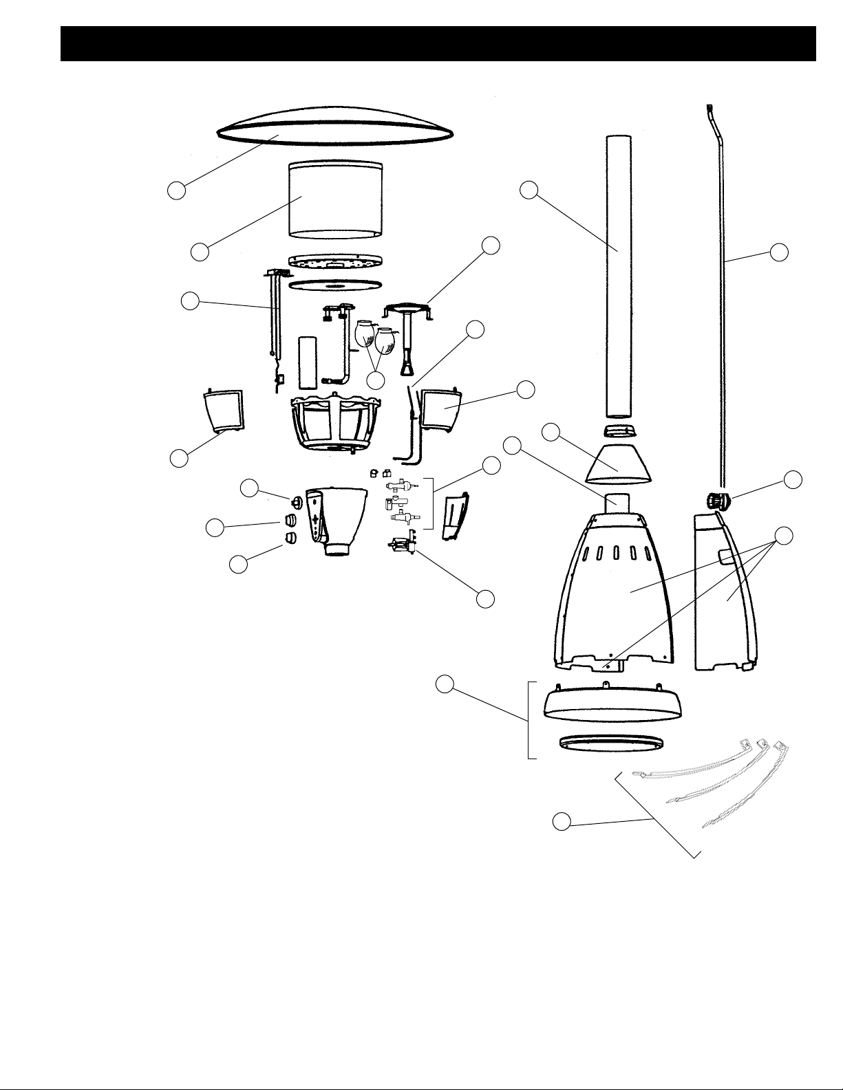
No. Part No. Description
1 5040-1561 Reflector
2 5040A5441 Pilot Assembly (Including tip switch)
3 5040-1211 Glass Frame
4 5040-1491 Heater Knob
5 5040-1501 Lantern Knob
6 5040-1471 E.I. Button
7 5040-3101 Electrode
8 5040-1431 Glass
9 5040-5571 Lantern & Heater Valve Assembly
10 5040-2211 Igniter
11 5040-5251 Regulator
12 5040-5641 Gas Hose Less Regulator
13 21A122 Insta-Clip Mantle
5040-0851 Hardware Kit Complete
14 5040-4411 Three Panels (Painted)
5040-4421 Three Panels (Stainless Steel)
15 5040-4401 Post (Painted)
5040-3391 Post (Stainless Steel)
16 5040-1751 Base Assembly
17 5040-4811 Post Mount (Painted)
5040-4801 Post Mount (Stainless Steel)
18 5040-1251 Post Mount Cover (Painted)
5040-1261 Post Mount Cover (Stainless Steel)
19 5040-0711 Three Support Brackets (Painted)
5040-0701 Three Support Brackets (Stainless Steel)
20 5040-1151 Heater Burner Screen
21 5040-1161 Burner
Replacement Parts for 5040 A Series
Page 3
© 2003 The Coleman Company, Inc.
3600 North Hydraulic, Wichita, KS 67219 U.S.A.
1-800-835-3278 or TDD 316-832-8707
Coleman
®
and are registered trademarks
of The Coleman Company, Inc.
3
Heater Manual
Table of Contents
For Repair or Replacement of: Page
Reflector 4
Burner Screen 4
Burner 5
Mantle Electrodes 5
Knob(s) or Igniter 6
Burner Caps 7
Pilot/Burner Electrode 7
Tip Switch
Mantle Section
Gas Tips, Burner Gas Line
Valve(s) and/or Valve Manifold
Troubleshooting 8-11
®
Page 4
4
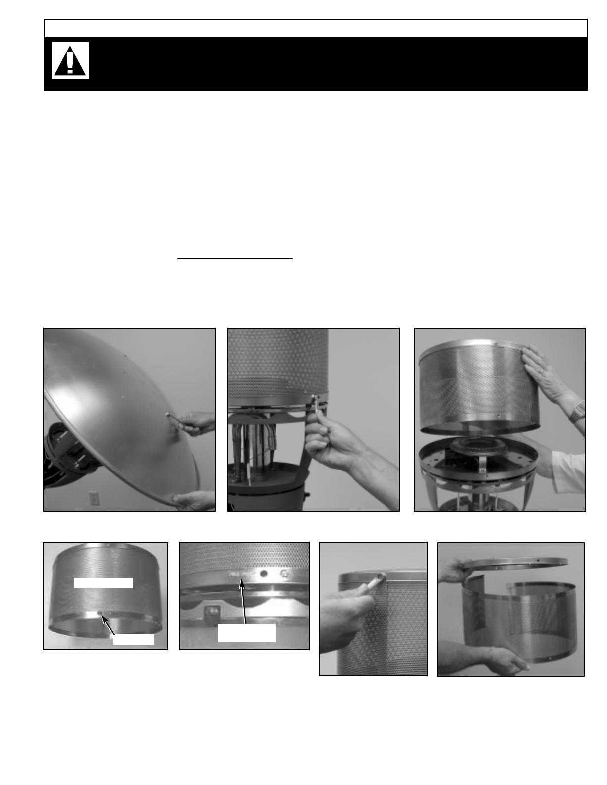
To repair or replace reflector, refer to Figure 1.
Remove four hex-head screws holding reflector to burner head using a 11/32" wrench (Figure 1).
Also see Note #1.
To repair or replace burner screen, refer to Figures 1-5. To avoid cuts, do not run fingers or
hands along edges of thin sheet-metal parts.
Remove reflector (Figure 1). Remove 4 lower hex-head screws holding burner screen to burner
screen assembly bottom using a 7/16" wrench (Figure 2). Lift burner screen assembly top from
heater head (Figure 3). Also see Note #1. Remove 4 upper hex-head screws holding burner screen
to burner screen assembly top using a 7/16" wrench (Figure 4). Finally, remove burner screen
assembly top (Figure 5). Reassembly caution
: Edge of screen with holes closer to the edge goes
“up” on re-assembly (attached to screen assembly top). When reinstalling burner screen make
sure that the oval hole at the bottom edge of the burner screen (Figure 3-a) is lined up with the
hole in the burner screen bottom, marked Pilot Port (Figure 3-b).
Figure 1 Figure 2 Figure 3
Figure 4
Figure 5
Caution: After completion of repairs and before operating the patio heater, make
sure you read and follow all safety information in the Instructions for Use manual. If
you do not have this manual, contact Coleman at 1-800-835-3278 or TDD 316-832-8707.
Figure 3-a
Figure 3-b
Oval Hole
Burner Screen
Burner Screen
Bottom
Model 5040 A Repair Manual
Page 5

5
To repair or replace the burner, refer to Figures 1-3, and Figures 6-7.
Remove reflector (Figure 1). Remove burner screen assembly top as a unit by removing only the 4
lower hex-head screws holding the burner screen assembly top to its bottom using a 7/16" wrench
(Figures 2 and 3). Remove 2 burner bracket screws (Figure 6-a). Also see Note #1. Then lift burner
straight up to remove (Figure 7). When reinstalling the burner it may help to rotate it as it is pushed
down the center tube. Make sure the burner locating hole at the bottom of the burner (Figure 6) fits
over the valve/manifold boss. This can be verified by looking through the maintenance access opening (Figure 7-a).
To replace mantle electrode(s), refer to Figures 8-11.
Remove glass panels. Unplug electrode wire from igniter (Figure 9). Then remove electrode bracket
screw (Figure 10). Electrode can now be removed through the opening in the head frame (Figure 11).
Also see Note #1.
Figure 6-a
Figure 7 Figure 7-a
Figure 9
Figure 10
Figure 11
Figure 6
Locating
Hole
Figure 8
Valve/Manifold
Boss
Burner
Locating
Hole
Note #1: For difficult to remove screws, apply 3-in-1 oil, penetrating oil, or WD-40. Let sit for several hours or overnight,
then attempt to remove screws again.
Mantle
Electrode
Model 5040 A Repair Manual
Page 6

6
To replace knob(s), refer to Figure 12.
Note: Knobs are a friction fit. To remove pull straight out on knob (Figure 12). When replacing knob,
flat side of knob hole must match flat on shaft that extends from the control console.
To replace igniter, refer to Figures 9 and 13-14.
Remove 3 electrode wires from igniter (Figures 9 & 14). Remove igniter cap and battery (Figure 13).
Remove ribbed collar (Figure 13A). Now remove igniter through the maintenance port opening
(Figure 14A).
Figure 12
Figure 12A Figure 13
Figure 13A
Figure 14 Figure 14A
Model 5040 A Repair Manual
Page 7

7
To replace burner caps, refer to Figure 15.
Using a pair of pliers unscrew each burner cap as shown (Figure 15). When reinstalling burner caps
apply antiseize compound to the threads to make future removal easier.
To repair or replace pilot/burner electrode assembly (including thermocouple), return heater
head
to Service Center.
Keep glass, reflector, post, and base. Ship only your Parasol Head to the Service Center.
To replace tip switch, return heater head to Service Center.
Keep glass, reflector, post, and base. Ship only your Parasol Head to the Service Center.
To repair or replace mantle section burner tube/venturi assembly, return heater head to Service
Center.
Keep glass, reflector, post, and base. Ship only your Parasol Head to the Service Center.
To repair or replace gas tips, burner gas line, valve(s), valve manifold and/or hose, return
heater head to Service Center.
Keep glass, reflector, post, and base. Ship only your Parasol Head to the Service Center.
Figure 15
Page 8

8
1. My heater is “wobbly”
2. During assembly some holes
do not completely line up.
3. The three small holes,
spaced at 120 degrees each, at
the end of the post do not match
up with the holes in the post
mount.
4. Cannot remove the screws
that hold the reflector to the
heater head.
Cannot remove screws that hold
burner screen to burner screen
base (or burner screen top).
Cannot remove the screws that
hold the burner assembly to the
burner screen base.
Cannot remove the screws that
hold pilot/electrode assembly to
the burner screen base.
5. I need to send my heater
head out for repair, but I can not
get the hose/regulator assembly
up through the post.
Tighten all screws, including those under the
post mount cover. Replace any missing
screws. Be careful not to overtighten
screws, which may result in stripped
threads.
During assembly leave all screws loose until
all screws are in place. Then tighten. If you
need just a little more clearance in a nonthreaded hole, use a small, round file to
open up the hole a little. Do not file or drill
out threaded holes (the only exception is
item
A-1, “comments”).
Post is upside down! The three small holes
at 120 degrees spacing should match up
with the three threaded holes (tapped for 1024 threads) in the lower (small end) portion
of the heater head.
After letting the heater cool down for a while,
apply penetrating oil, kerosene, or WD-40 to
the perimeter of each screw and let soak for
several hours or overnight.
The regulator must be unscrewed from the
hose assembly in order to completely
remove the heater head from the Parasol
Heater post.
It is possible to drill out any holes with
stripped threads, and tap for use with
the next size screw.
The post mount holes are tapped for
1/4"-20 threads.
A screwdriver with a tip that is a good
fit to the screw head must be used.
To insure future ease of removal, use
antiseize compound on all screw
threads that are subjected to high
heat.
Caution: After completion of any repairs and before operating your Parasol Heater, make sure you
read and follow all safety information in the Instructions for Use manual. If you do not have this
manual, contact Coleman Consumer Service at 1-800-835-3278 or TDD 316-832-8707.
A. BASE, SHEET METAL, & POST COMPONENTS:
Problem Solution Comments
TROUBLESHOOTING - 5040A Series Parasol Heaters
Page 9

9
1. Rotary igniter is loose.
Battery-operated igniter is loose.
2. No spark is visible at electrodes when rotary igniter is
rotated (or when battery-operated igniter is actuated – 5040A
models only)
No “zap-zap-zap” is heard when
button on battery-operated igniter is pressed.
3. Mantle electrode is loose so
spark gap varies.
Pull igniter knob off (ref. Figures 12 & 12A in
5040 Series Repair and Replacement
Procedures) and tighten the mounting
screws.
Make sure that the ribbed plastic collar that
holds the battery-operated igniter to the control console is tight (ref. Figure 13). This will
insure that a grounding tab (not visible) is
making good contact.
The spark may be very difficult to see in daylight, but should be visible at night.
If mantle section or heater section will not
light using the igniter, check to see if electrode wires are firmly attached to the rear of
the igniter (ref. Figure 14).
Verify that electrode gap is no more than 1/8"
– 3/16" inch from the burner cap.
On battery operated igniters try installing a
new battery. Make sure that the ribbed plastic
collar that holds the battery operated igniter
to the control console is tight (ref. Figure 13
of the 5040A Series Repair and Replacement
Procedures). This will insure that a grounding
tab (not visible) is making good contact.
Replace battery.
Check to see if electrode bracket screw is
loose. If so tighten screw. If ceramic is loose
in bracket, it may be possible to tighten it
using pliers or a vise. If ceramic is cracked,
replace with a new mantle electrode assembly.
No cause for concern exists when
spark is not visible providing mantle
and heater sections light properly.
The mantle section on all models can
be lighted using a match if the igniter
is not working properly.
The heater section on “A” model
Parasol Heaters can be lighted with a
long fireplace match through the pilot
port hole in the burner screen if the
igniter is not working.
If a spark appears anywhere along the
length of the ceramic, this is an indication that the ceramic is cracked and
should be replaced with a new electrode assembly.
B. ROTARY and BATTERY-OPERATED IGNITERS:
Problem Solution Comments
Page 10

10
1. New mantles will not light
using the igniter.
Mantles will not light using a
match.
2. New mantles are dim after
being lighted.
3. New mantles are dim after
being lighted or go out or
become dim when lighting of the
burner section is attempted.
After tying new mantles to the burner caps,
they should be burned off using a match
before use. The gas controls should be “off”.
After “burn-off” it is suggested that you light
them the first time using a match. Once
lighted, they will fill out a bit, then should
relight O.K. using the igniter.
Make sure your propane tank is not empty
and that the propane tank valve and
heater’s mantle section valve are both
turned “on”.
Regulator pressure setting may be too low.
Replace regulator.
If all the above have been ruled out, then
the mantle gas tip may be restricted.
Replace mantle gas tip. Contact Coleman
Customer Service (1-800-835-3278).
Make sure that item C-1 has been
observed. Make sure that the string (or wire
clip on Insta-light mantles) is located in the
burner cap groove. If the mantle is tied higher up on the burner cap, light output will be
less than normal.
Sometimes spiders leave webs inside the
burner/venturi tube(s), causing problems. A
Q-tip can be used to clean out the burner
caps and burner tubes on “dash” model
Parasol Heaters. On “A” models the burner
caps will first need to be removed then the
burner tube can be cleaned out using a Qtip. Compressed air blown up through the
burner caps may also help. This may be
necessary to reach the venturi portion of the
assembly.
The regulator pressure setting may be too
low. Replace regulator.
Regulator pressure setting problem.
Replace regulator.
Note: When a new tank has just been
installed there will be a delay while
the propane flows up the hose to the
mantles.
Mantles with holes or tears will not
work properly and should be replaced.
C. MANTLE (LIGHT) SECTION:
Problem Solution Comments
Page 11

11
1. Pilot will not light using the
igniter (or with a long match –
“A” models only).
2. Pilot flame is long and yellow
(and main burner is not yet on).
3. Burner lights, but flame is
irregular and seems to burn
around only part of the burner’s
periphery.
4. Pilot lights, but burner will not
light.
Make sure propane tank is not empty and
that propane tank valve and heater valve are
both turned “on”.
Note: Valve must be in “pilot” position and
must be pressed “in” while igniter is actuated, otherwise pilot will not light. After pilot
lights you must hold the knob “in” for up to
45 seconds in order to engage the thermocouple. Then the knob may be released and
rotated “full on” to light the heater burner.
If igniter wire to pilot/electrode assembly is
loose (or is not connected), then pilot will not
light using igniter. Wire must be reconnected
or replaced if damaged. Contact Coleman
Customer Service (1-800-835-3278).
Pilot air port may be restricted or partially
restricted. Blockage will need to be removed.
Contact Coleman Customer Service
(1-800-835-3278).
Pilot air port may be restricted. Blockage will
need to be removed. Contact Coleman
Customer Service (1-800-835-3278).
Some of the spot welds holding the burner
assembly together may have failed. Replace
burner assembly.
Main burner gas tip may be restricted.
Replace main burner gas tip. Contact
Coleman Customer Service
(1-800-835-3278).
Note: When a new tank has just been
installed there will be a delay while
the propane fills the hose as it flows
up to the pilot.
Make sure all wires that attach to the
back of the igniter are firmly in place.
If spark gap at electrode is too wide,
hard lighting or no lighting may result.
Contact Coleman Customer Service
(1-800-835-3278).
Note: It is normal for the pilot flame
length to increase when the main
burner is on.
D. HEATER (BURNER) SECTION:
Problem Solution Comments
5040-053 (10/24/2003)
 Loading...