

Coleman 300 Series, 400 Series Owner's Manual

Owner’s Manual
300 & 400 Series
2006

Copyrights and Trademarks
©Copyright 2006MAAX Spas (Arizona), Inc.. All rights reserved. No parts of this publication may be reproduced, stored in a retrieval system, or transmitted, in any form or by any means (electronic, mechanical, photocopying, recording or otherwise), without prior written permission.
Horizon™, Spectrum™, California Cooperage
®
, Journey™, Powerworks™, Comfort Collar™, ThermoLock™, Foot Relief Zone™, CleanZone™, DuraMaax™, and GRIP™ are registered trademarks of
Maax Spas.
Disclaimer:
The information in this manual is accurate to the best of MAAX Spas (Arizona), Inc.’s knowledge. However,
MAAX Spas (Arizona), Inc. assumes no responsibility for errors or omissions. Nor is any liability assumed for
damages resulting from use of the information contained herein.
Congratulations on your purchase of a Coleman
®
Spa.
Your Owner’s Manual provides installation, operation and maintenance instructions. Please review it and keep it for future reference.
Save These Instructions
Owner’s Record Information
Date Purchased___________________________________________________
Purchased From __________________________________________________
Phone Number ___________________________________________________
Installed By _____________________________________________________
Serial Number ___________________ Model _________________________

IMPORTANT
SAFETY
WARNINGS
NOTE: When installing and using this equipment,
basic safety precautions should always be taken to
reduce the risk of electrical shock, to ensure safe
usage, and to safeguard the user’s health.
(1)
Read and Follow ALL
Instructions!!
(2) Ground All Metal and
Electrical Equipment!
(3) A green colored terminal or a terminal marked G,
GR, Ground, Grounding, or the international
symbol* is located on the side of the supply
terminal box or compartment. This terminal must
be connected to the grounding means provided in
the electric supply service panel, using a continuous copper wire equivalent in size to the circuit
conductors supplying this equipment.
*IEC Publication 417, Symbol 5019.
(4) At least two lugs marked “BONDING LUGS” are
provided on the external surface or on the inside
of the supply terminal box or compartment.
Connect the local common bonding grid (household ground) in the area of the hot tub or spa to
these terminals, using an insulated or bare copper
conductor not smaller than No. 6 AWG.
(5) All field-installed metal components such as rails,
ladders, drains or similar hardware located within
5 ft. of the spa or hot tub shall be bonded to the
equipment grounding bus with copper conductors
not smaller than No. 6 AWG.
(6)
SAVE THESE
INSTRUCTIONS.
WARNING: Children should not use spas or hot tubs
without adult supervision
and
AVERTISSEMENT: Ne pas laisser les enfants utilis-
er une cuve de relaxation sans surveillance
WARNING: Do not use spas or hot tubs unless all
suction guards are installed to prevent body and hair
entrapment
and
AVERTISSEMENT: Pour éviter que les cheveux ou
une partie du corps puissent être aspirés, ne pas utiliser une cuve de relaxation si les grilles de prise d’aspiration ne sont pas toutes en place
WARNING: People using medications and/or having
an adverse medical history should consult a
physician before using a spa or hot tub
and
AVERTISSEMENT: Les personnes qui prennent des
médicaments ou ont des problèmes de santé devraient
consulter un médecin avant d’utiliser une cuve de
relaxation
WARNING: People with infectious diseases should
not use a spa or hot tub
and
AVERTISSEMENT: Les personnes atteintes de maladies infectieuses ne devraient pas utiliser une cuve de
relaxation
WARNING: To avoid injury exercise care when
entering or exiting the spa or hot tub
and
AVERTISSEMENT: Pour éviter des blessures, user
de prudence en entrant dans une cuve de relaxation et
en sortant
WARNING: Do not use drugs or alcohol before or
during the use of a spa or hot tub to avoid
unconsciousness and possible drowning
and
AVERTISSEMENT: Pour éviter l’évanouissement et
la noyade eventuelle, ne prendre ni drogue ni alcool
avant d’utiliser une cuve de relaxation ni quand on s’y
trouve
WARNING: Pregnant, or possibly pregnant, women
should consult a physician before using a spa or hot
tub
and
AVERTISSEMENT: Les femmes enceintes, que leur
grossesse soit confirmée ou non, devraient consulter
un médecin avant d’utiliser une cuve de relaxation.
i

WARNING: Water temperature in excess of 100°F
(38° C) may be injurious to your health
and
AVERTISSEMENT: Il peut être dangereux pur la
santé de se plonger dans de l’eau à plus de 38° C
WARNING: Before entering the spa or hot tub measure the water temperature with an accurate thermometer
and
AVERTISSEMENT: Avant d’utiliser une cuve de
relaxation mesurer la temp
érature de l’eau à l’aide
d’un thermomètre précis
WARNING: Do not use a spa or hot tub immediately following strenuous exercise
and
AVERTISSEMENT: Ne pas utiliser une cuve de
relaxation immédiatement après un exercice fatigant
WARNING: Prolonged immersion in a spa or hot
tub may be injurious to your health
and
AVERTISSEMENT: L’ utilisation prolongée d’une
cuve de relaxation peut être dangereuse pour la santé
WARNING: Do not permit electric appliances (such
as a light, telephone, radio, or television) within 5 ft.
(1.5m) of the spa or hot tub
and
AVERTISSEMENT: Ne pas placer d’apareil élec-
trique (luminaire, téléphone, radio, téléviseur, etc) à
moins de 1.5, de cette duve de relaxation
WARNING: Maintain water chemistry in accordance
with manufacturer
’s instruction
and
AVERTISSEMENT: La teneur de l’eau en matières
dissoutes doit être conforme aux firectives du fabricant.
WARNING: The use of alcohol or drugs can greatly
increase the risk of fatal hyperthermia in hot tubs and
spas
and
A
VER
TISSEMENT:
La consommation d’alcool ou
de drogue augmente considérablement les risques
d’hyperthermie mortelle dans une cuve de relaxation.
HYPERTHERMIA
The causes, symptoms, and effects of hyperthermia
may be described as follows:
Hyperthermia occurs when the internal temperature of
the body reaches a level several degrees above the normal body temperature of 98.6°F (37° C). The symptoms of hyperthermia include drowsiness, lethargy,
and an increase in the internal temperature of the body.
The effects of hyperthermia include
(a) unawareness of impending hazard;
(b) failure to perceive heat;
(c) failure to recognize the need to exit spas;
(d) physical inability to exit spa;
(e) fetal damage in pregnant women; and
(f) unconsciousness and danger of drowning.
ii

Safety Warnings . . . . . . . . . . . . . . . . . . . i,ii
Table of Contents . . . . . . . . . . . . . . . . . . iii
Important Safety Instructions . . . . . . . . 1
Do’s and Don’ts . . . . . . . . . . . . . . . . . 2
Hyperthermia . . . . . . . . . . . . . . . . . . . 2
Spa Installation . . . . . . . . . . . . . . . . . . . . 3
Site and Positioning . . . . . . . . . . . . . . 3
Outdoor Installation . . . . . . . . . . . . . . 3
Indoor Installation . . . . . . . . . . . . . . . 3
Spa System Components . . . . . . . . . . . . 4
Spa Components . . . . . . . . . . . . . . . . . . . 5
Jets, Air Controls and Air Injectors . . . 6
Jets . . . . . . . . . . . . . . . . . . . . . . . . . . . 6
Cleaning or Replacing Jets . . . . . . . . . 6
Comfort Collar . . . . . . . . . . . . . . . . . . 6
Air Controls . . . . . . . . . . . . . . . . . . . . 6
Electrical Information . . . . . . . . . . . . . . 7
Important Safety Instructions . . . . . . . 7
Ground-Fault Circuit-Interrupter . . . . 7
Installation Options . . . . . . . . . . . . . . 7
. . . . . . . . . . . . . . . . . . . . . . . . . . .
Controls Applicability . . . . . . . . . . . . . . 9
Start Up Procedures . . . . . . . . . . . . . . . . 10
Priming Your Spa . . . . . . . . . . . . . . . . 10
Powerworks™ 460 Control System
Operating Instructions . . . . . . . . . . . . . . 11
User’s Pads . . . . . . . . . . . . . . . . . . . . . 12
Temperature . . . . . . . . . . . . . . . . . . 13
Temperature Lock and Unlock . . . . 13
Panel Lock and Unlock . . . . . . . . . 14
Light . . . . . . . . . . . . . . . . . . . . . . . . 14
Standard/Economy/Sleep Modes . . 14
Setting Time and Filtration Cycles . 14
Setting the Time . . . . . . . . . . . . . . . 14
Preset Filter Cycles . . . . . . . . . . . . . 14
Changing Filter Cycles . . . . . . . . . . 15
Clean Up Cycle . . . . . . . . . . . . . . . 15
Inversion Feature . . . . . . . . . . . . . . . . 15
T
urbo
Air Booster (Optional) . . . . . . . 15
Air Massage (Optional) . . . . . . . . . . . 15
Digital Fiber Optics (Optional) . . . . . 16
Ozone Operation (Optional) . . . . . . . . 16
Optional Entertainment System . . . . . 16
Powerworks™ 167 Control System
Operating Instructions . . . . . . . . . . . . . . 17
User’s Pads . . . . . . . . . . . . . . . . . . . . . 17
Temperature Controls . . . . . . . . . . . 18
Light . . . . . . . . . . . . . . . . . . . . . . . . 18
Standard/Economy Mode . . . . . . . . 18
Filtration Cycles . . . . . . . . . . . . . . . . . 18
Preset Filter Cycles . . . . . . . . . . . . . 19
Changing Filter Cycles . . . . . . . . . . 19
Clean Up Cycle . . . . . . . . . . . . . . . 19
Fiber Optics (Optional) . . . . . . . . . . . 20
Ozone Operation . . . . . . . . . . . . . . . . 20
Safety Features . . . . . . . . . . . . . . . . . . . . 21
Automatic Time Outs . . . . . . . . . . . . . 21
LCD Equipment Safety Messages . . 21
Common Messages . . . . . . . . . . . . . . 22
Maintenance . . . . . . . . . . . . . . . . . . . . . . 23
Water Chemistry . . . . . . . . . . . . . . . . . 23
Sanitizing . . . . . . . . . . . . . . . . . . . . . . 23
pH Level . . . . . . . . . . . . . . . . . . . . . . . 23
Water Maintenance With the
CleanZone
™ Water Treatment System 23
Sanitizing With Ozone . . . . . . . . . . . . 23
Specialty Chemicals . . . . . . . . . . . . . . 23
Draining Your Spa . . . . . . . . . . . . . . . 24
Filter Maintenance . . . . . . . . . . . . . . . 24
Winterizing . . . . . . . . . . . . . . . . . . . . . 25
Spa Cabinet Care . . . . . . . . . . . . . . . . 25
Spa Surface Care and Cleaning . . . . . 25
Light Bulbs . . . . . . . . . . . . . . . . . . . . . 25
Common Water Problems . . . . . . . . . 26
Common Hardware Problems . . . . . . 28
Spa Soaking Guidelines . . . . . . . . . . . . . 30
460 System Wiring Diagram
. . . . . . . . . . . . 31
167 System Wiring Diagram
. . . . . . . . . . . . 32
165 System
W
iring Diagram
. . . . . . . . . . . .
33
iii

IMPORTANT
SAFETY
INSTRUCTIONS
1.Read and follow all instructions.
2.Save these Instructions.
3. Never allow children to access or use this
product unless closely supervised by an adult
at all times.
4. Never connect unit to a power supply with a
load controller.
5. Never operate spa if the suction fittings are
broken or missing.
6. Never replace a suction fitting with one rated
less than the flow rate marked on the original
suction fitting.
The suction fittings in this spa are sized to
match the specific water flow created by the
pump. Should the need arise to replace the
suction fittings or the pump, be sure that the
flow rates are compatible.
To avoid/reduce risk of injury and/or
drowning:
1. The water temperature in a spa should never
exceed 104°F (40° C). This temperature is
considered safe for a healthy adult. Lower
water temperatures are recommended for
young children and elderly adults, and when
spa usage exceeds 10 minutes. Consult your
physician or pediatrician to determine safe
temperature limits.
NOTE: Refer to information on hyperther-
mia on page 2.
2.
Since excessive water temperatures have a
high potential for causing fetal damage during
the early months of pregnancy, pregnant or
possibly pregnant women should check with
their physician before entering spa.
3. Before entering a spa, the user should verify
the water temperature with an accurate thermometer since the tolerance of water temperature regulating devices varies.
4. The use of alcohol, drugs, or medications
before or during spa use may lead to unconsciousness with the possibility of drowning.
5. Persons suffering from obesity or with a medical history of heart disease, circulatory problems, or diabetes should consult a physician
before using a spa.
6. Persons using medications should consult a
physician before using a spa since some medications may induce drowsiness while other
medications may affect heart rate, blood pressure, and circulation.
To avoid risk of electrical shock:
1. Only use the wire connector provided on this
unit to connect a minimum No. 6 AWG (5.15
mm
2
) solid copper conductor between this unit
and any metal equipment, metal enclosures of
electrical equipment, metal water pipe, or conduit within 5 ft. (1.5 m) of the unit.
2. Install at least 5 ft. (1.5m) from all metal surfaces. Spa may be installed within 5 feet of a
metal surface if each metal surface is permanently connected by a minimum No. 6 AWG
(5.15mm2) solid copper conductor attached to
the wire connector on the terminal box that is
provided for this purpose.
3. Do not permit any electric appliance, such as a
light, telephone, radio, or television within 5
ft. (1.5m) of a spa.
NOTE: Check with your state/local code
enfor
cement of
ficer to determine electrical
code r
equir
ements and compliance. Use a
qualified licensed electrician to complete all
spa final electric connections.
Caution: Risk of electrical shock.
Read and follow all instructions.
1

The electrical supply for this product must
include a suitably rated switch or circuit
breaker to open all ungrounded supply conductors to comply with Section 422-20 of the
National Electrical Code (NEC) ANSI.NFPA
70-1987. This disconnecting means must be
readily accessible for operation but installed at
least 5 ft. (1.5m) from the spa as required to
comply with local code requirements. All
electrical connections should comply with
Article 680-D of the NEC.
4. Install to provide drainage of compartment for
electrical components.
Do’s and Don'ts
For years of spa enjoyment:
Do:
• Save these instructions!
• Replace the cover immediately after use.
• Keep the cover locked when spa is not in use.
• Be aware of the dangers of a wet and slippery
surface. Use caution when entering and exiting
your spa.
• Have a licensed electrician make all final elec-
trical connections.
• Replace worn, frayed or broken electrical cords.
• Keep the water chemistry correctly balanced.
Untreated spa water will cause problems with your
spa and equipment as well as being a health risk.
• Clean the spa filter monthly or as needed.
• Position the spa so that all sides remain accessi-
ble for maintenance.
• Use a bathing cap for long hair
.
• Refer to information on hyperthermia (this page).
• Use only authorized spa care products for the
best performance and to keep the water properly
balanced.
Don't:
• Use the spa at 104° F (40° C) for long periods of
time (more than 30 minutes). See Hyperthermia,
this page.
• Use an extension cord to power your spa.
• Allow anyone to stand on the spa cover. It is not
designed to support weight.
• Power the spa unless it is filled with water to the
water level mark on the Weir door.
• Operate the pump on high speed for extended
periods of time with the cover in place. Extended
operation can cause heat build-up and interfere
with spa operation.
Hyperthermia
The causes, symptoms, and effects of hyperthermia may be described as follows: Hyperthermia occurs when the internal temperature
of the body reaches a level several degrees
above the normal body temperature of 98.6º F
(37° C). The symptoms of hyperthermia
include an increase in the internal temperature
of the body, dizziness, lethargy, drowsiness,
and fainting. The effects of hyperthermia
include (1) failure to perceive heat, (2) failure
to recognize the need to exit spa or hot tub, (3)
unawareness of impending hazard, (4) fetal
damage in pregnant women, (5) physical
inability to exit the spa or hot tub, and (6)
unconsciousness resulting in the danger of
drowning.
Warning: The use of alcohol, drugs, or medication can greatly increase the risk of fatal
hyperthermia.
2

Spa Installation
The electrical supply for this product must include
a suitably rated switch or circuit breaker to open all
ungrounded supply conductors to comply with Section
422-20 of the National Electrical Code, ANSI/
NFPA70-1987. The disconnecting means must be
readily accessible but installed at least 5 feet (1.5
meters) from the spa water. All electrical connections
should comply with article 680-D of the NEC.
Site and Positioning
Locate the spa on solid, level foundation or flooring, keeping in mind the weight of the filled spa (in
excess of 4,000 lbs. on some models). If you have any
doubts about the load bearing ability of your chosen
site, contact an architect or a building contractor. The
entire perimeter of the spa cabinet and the spa bottom
must be evenly supported.
If your spa is installed outdoors, we recommend
that you provide a concrete pad for the spa to rest on
(8ft. x 8ft. x 4in. level pad).
Failure to provide a level
surface could structurally damage your spa and
void the warranty.
The spa must be installed to allow access for service and maintenance on all four sides; therefore, below
grade level installation is not recommended.
Outdoor Installation
The following considerations apply when
installing your spa outdoors:
1. Local codes pertaining to fencing.
2. Local electrical and plumbing codes.
3. View from your house.
4. Wind direction.
5. Exposure to sunlight.
6. Location relationship to trees (twigs, leaves and
shade).
7.
Dressing and bathroom location.
8. Storage area for maintenance equipment and
chemicals.
9. Location to facilitate adult supervision.
10.
Landscaping and nighttime lighting.
11. Accessibility to equipment.
12. Power supply location and foot traffic.
Indoor Installation
The following considerations apply when
installing your spa indoors:
1. Indoor spas promote high humidity. Using either
ventilation fans or commercial grade de-humidifiers will help to reduce the humidity. Consult
your dealer for details.
2. Floor drains must be provided near the spa to
drain off water that may cause falls and /or
water damage.
3. Floor area should be flat with a non-skid finish.
Carpeting is not recommended.
4. Walls, ceilings, woodwork should be made of
materials capable of withstanding high humidity
(redwood, cedar).
5. Be sure floor load bearing capacities are adequate
to support the concentrated spa weight.
6. Spas should be double checked for leaks before
installing to avoid possible water damage. Dealer
installation may include this service.
7. Indoor sunrooms are capable of maintaining high
ambient temperatures which may effect the spa
water temperature. It is NOT recommended that
you operate your filter cycles for longer than 4
hours per day under these conditions.
Danger: Electrical shock risk. Install at
least 5 ft. (1.5m) from all metal surfaces.
3
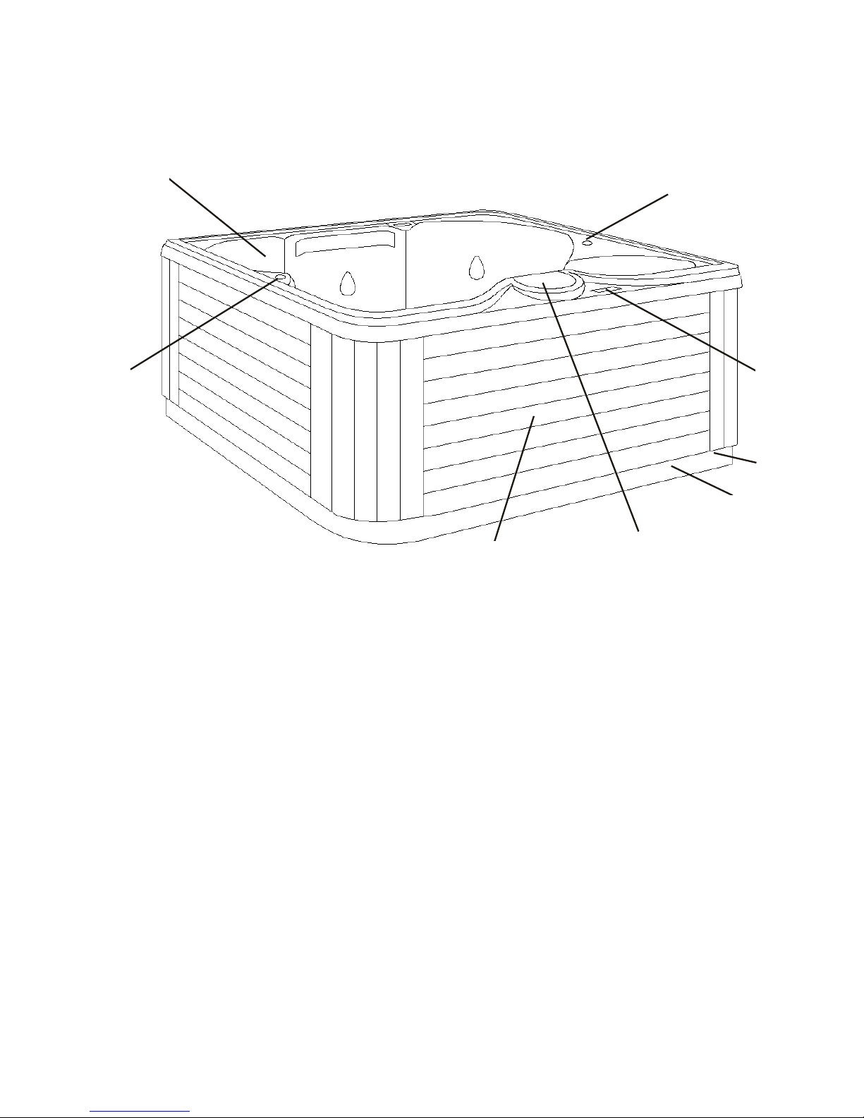
A. Filter Skimmer/Weir Door: Removes floating
debris from the water surface, provides a water
return path to equipment, and houses water filter
element.
B. Topside Control Panel: Used to control temper-
ature setting, pump for jets, and light.
C. Air Controls: Increases or decreases air entering
the jets. Close during heating for maximum ef
fi-
ciency.
D. Comfort Collar™ Valve: Used to control water
flow to Comfort Collar jets. (Not applicable to all
Models.).
E.
Equipment Pack Service Panel (no user serviceable parts): Spa support system consisting of
one or two pumps, heater, and associated electrical controls (not shown).
F. Drain Access (Adjacent to the equipment
service panel): Spa drain faucets are located on
the kickplate.
G. Manufacturer’s Identification Label: Contains
identification information for warranty service
(serial number, model number, etc.) and electrical
information (ampere rating and ampere requirements). Located on the kickplate, on the same
side as the topside control.
H. Diverter Valve: Used to direct the flow of water
from jets to the open seating area jets in the spa.
(Not applicable to all Models.)
Spa System Components
D
F
G
C
B
E
A
H
4
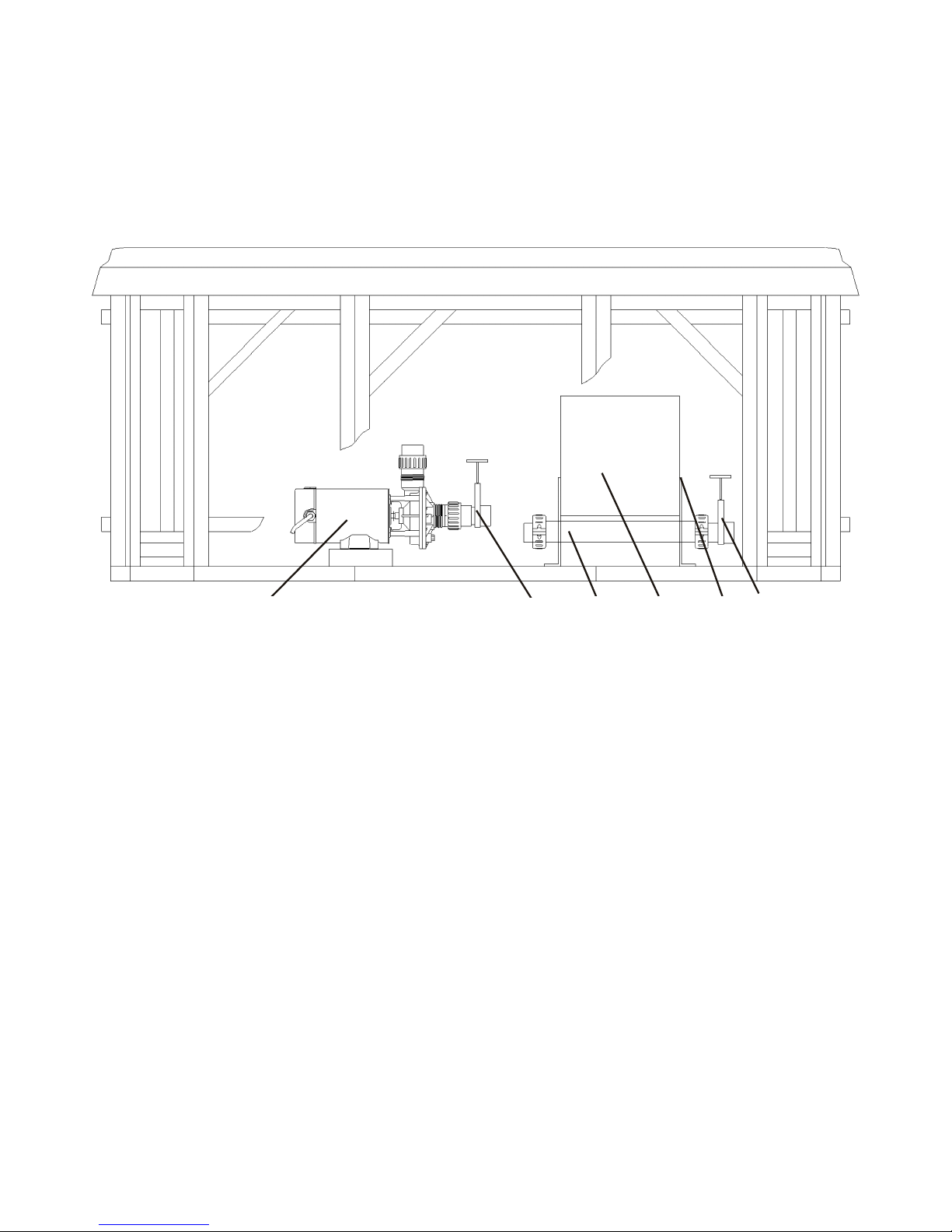
A. Pumps (One pump or two pumps, depending
on model): Low speed for efficient water circu-
lation during filtration and heating; high speed for
maximum action of the jets. The pump functions
are activated by topside controls.
B.
W
arning and Installation Label:
Contains
important safety information and installation
instructions.
C.
Slice
V
alve:
Used to shut of
f water flow from the
spa to the equipment while servicing. Quantity
will vary depending on model. All should be open
during normal operations.
D. Electrical Connections: Contains outlets for
electrical plug connections. Connections are
made during manufacture of the spa.
E. Heater Assembly: Thermostatically controlled
and equipped with an overheat safety shut-off.
Spa Components
Reference only. Equipment is not always as shown.
Note: No consumer serviceable parts. We recommend that only an authorized
service technician perform hot tub repair or service.
A
B
C
DE
C
5

Jets and Air Controls
Jets
All spa jets are individually engineered to provide
a unique hydro-massage. Depending on the model,
your spa will have a combination of the following jets:
Cyclone Therapeutic (XL Cyclone, LS Cyclone, &
Cyclone)
:
Positioned to focus on large muscle groups, these
jets deliver a concentrated, high volume stream of
water for a deep massage. Each jet is fully
adjustable, allowing users to set the water flow to
the most comfortable setting. The nozzle can be
rotated to target sore muscle areas.
Cyclone Turbo Swirl Jets (
XL Cyclone, LS Cyclone, &
Cyclone
):
Positioned to focus on muscle tension zones, these
jets deliver a spinning V-shaped water stream for a
gentle, pulsating massage. Each jet is fully
adjustable, allowing users to set the water flow to
the most comfortable setting.
Whirlpool:
Positioned to create overall water circulation, this
mult-purpose, high volume jet provides whirlpool
action throughout the entire spa.
Cluster Jets:
Positioned in the footwell or shoulder areas of the
spa, these jets deliver a penetrating massage to dissolve tension. This jet may be the entry point for
ozone produced during the automatic filtration
cycles, and, as such, is not adjustable. Note: Ozone
production is suspended when other functions are
activated on the control panel by the spa user.
All full sized jets are adjustable from a fully open to
closed position. It is very important that you
NEVER
SHUT
ALL
FULL
SIZED JETS OFF
A
T
ONE
TIME!
Cleaning or Replacing Jets
Hard water can cause calcium/mineral buildup
that can restrict or bind the jets. A jet consists of a face
plate and a nozzle. Rotate these parts weekly and
remove/clean monthly to ensure free movement..
Note: It is not necessary to drain the spa to clean or
remove the jets.
Rotating the jet face plate and nozzle
· Rotate the jet face left and right (open and closed).
· Return the face plate to the full open position.
· Turn the jets on to high speed.
· Twist the nozzle left and right.
· Rotate the nozzle in the socket.
Note: If the jet insert disengages from the spa
housing, see steps to reinstall below.
Cleaning the jets
To remove the jet insert, use the palm of your hand
to exert pressure on the face of the jet. Turn counterclockwise until the jet "clicks". Gently pull the jet
assembly from the housing.
To clean the jet insert and housing, use a pressurized
hose and spray the inside of the jet. Soak the jet
in a diluted spa cleaning solution, rinse. Wipe the
inside of the housing to remove any debris.
To reinstall the jet, line up the tab on the backside of
the barrel with the groove in the body. Use the palm of
your hand to gently tab the jet until it snaps into
position.
Comfort Collar™
Select models in the 400 series are equipped with
special above-the-waterline neck jets in the Comfort
Collar™. The intensity of the water flow to these jets
can be controlled by turning the valve adjacent to the
therapy seat.
Note: The Comfort Collar™ jets in all Base models
are not equipped with a control valve.
Air Controls
The intensity of the jet action can be controlled by
altering the amount of air injected with water through
the jets.
Y
our spa has 2 to 4 air controls located on the
lip of the spa. Each control activates air to specific jets
in the spa allowing you to create various combinations
and levels of jet action to suit individual preferences.
Turn the control counter-clockwise to turn the air
off and clockwise to turn air on.
Note: Air controls should be closed during heating
cycles for maximum energy efficiency.
Note: If spa is equipped with the Aeromax option,
one contr
ol should be left open at all times.
6

Electrical Information
Important Safety Instructions
All electrical connections to this spa package
MUST be accomplished by a qualified licensed
electrician in accordance with the National
Electrical Code (NEC) and with state/local electrical codes in effect at the time of installation.
NOTE:
Prior to performing any service to the spa
equipment, turn OFF all primary electrical power at
the main circuit breaker or disconnect panel.
To make spa electrical connections, remove the
exterior equipment access panel, locate the electrical
control box, remove the control box cover and follow
the wiring diagram on the inside of the control box
cover.
Connections should be made using copper conductors only. Connecting wires, circuit breakers, or fuses
must all be sized to accommodate the Total Ampere
load as specified on the equipment label.
This equipment is designed to operate on 60Hz
alternating current only, at 240 volts or 120 volts, as
required.
NOTE: All unions must be hand-tight and all slice
valves must be locked in the OPEN position before filling or refilling spa! A clip is provided to help keep the
slice valve open. Run spa and check for union leaks
before reinstalling front panel.
Ground-Fault Circuit Interrupter
A qualified licensed electrician shall connect the
spa to a circuit protected by a GFCI.
This is a require
-
ment by the National Electric Code, article 680-42,
and is also in compliance with Underwriter’s
Laboratories, Inc.
Installation Options
While knockouts are provided in the cabinet base to
bring the conduit to the equipment compartment, a
hole may need to be drilled in the pedestal or base if an
alternate electrical service entrance is desired.
The 300 Series Model 351 Base unit is convertible
to either 120 volt or 240 volt electrical service. All
other models can only be connected to a 240 volt electrical service.
120 Volt Installation
Model:
• The 300 Series Model 351 Base.
Electrical Requirements:
• 120 Volts, 60Hz, Single Phase, 40 amp. or *20 amp
3-wire service, (including ground.)
*20 Amp Option
Note:
The heater can be activated only with the
pump on low speed. Only the light can be operating at the same time without disabling the heater.
See your authorized Coleman Spas® dealer to
select this option.
• 300 Series spas installed for 120 volt operation require a 3-wire, 20 or 40 amp, 120 volt subfeed in non-metallic pipe to the spa equipment
compartment (line 1, neutral and ground). A green
colored terminal (or wire connector marked “G”,
or “GR”, “Grounding”) is provided in the control
box. To reduce the risk of electrical shock, connect
this terminal or connector to the grounding terminal of your electrical service or supply panel with a
continuous green insulated copper wire equivalent
to the circuit conductor supplying this equipment,
but no smaller than No. 12 AWG. A second pressure wire connector is provided on the surface of
the control box for bonding to local ground points.
To reduce the risk of electrical shock, this connector should be bonded with a No. 6 AWG copper
wire to any metal ladders, water pipes, or any metal
within 5 feet of the spa.
Copper wire is strongly recommended for all
electrical connections.
Caution: Risk of electrical shock.
Read and follow all instructions.
7
 Loading...