

Page 1
i IIIII I II
®
ASSEMBLY
INSTRUCTIONS
3000
SERIES
WARNING:
THE EDGES OF SHEET METALPARTSCAN CAUSE INJURY
IF NOT HANDLEDWITH CARE.
USE ,EXTREME CAUTION!
I I
IMPORTANT!
TO ENSURE PROPER GAS FLOWs BURNER
CONTROL VALVES MUST BE "OFF" BEFORE
OPENING THE GAS CYLINDER VALVE,
I lU
Las lnstrucciones de Ensamlllajo on e,,pa_ol en la pallina 21.
11412077AX 01/01 (REV,010603)
Coleman Company, Inc.
410t Howard Bush Drive
Neosho, Missoud 64850
Internet site:
www.bbqhq, com
1-800-356-3612 _
Page 2

BEFOREYOU BEGIN ASSEMBLING
YOUR NEW QUALITY COLEMAN
GAS BARBECUE GRILL:
=_ FOR EASE OF ASSEMBLY, leave the grill on
the inside bottom foam packing tray unUI the
wheels have been attached. (See representative
example at right). Remove the outside foam from
the right and left sides of the frame base at this
time.
c_ Remove allcartons locatedon top of the barbecue
grill base and set aside
START THE COOKING GRIDS
SEASONING PROCESS BEFORE
ASSEMBLING YOUR GRILL !
CAST iRON GRIDS
:_ Cast Irongridsare on select modelsonly.
<, Your cast iron grids may have some rusting.
This is normal.To removethe rust,scourthe
rusty areaswith steelwool,i.e. SOS pad, until
all traces of rust are gone. Wash, dry and
seasongrids.
SEASONING CAST iRON GRIDS
SEASONINGISTHEPROCESSOFALLOWINGOILTOBE
ABSORBEDINTOTHEIRON,CREATINGANON-S'I]CK,
RUSTPROOFFINISH.HERE'SHOWTODOIT:
Preheat Oven to 350°F.
Wash with hot, soapy water and a stiff brush.
Rinse and dry completely.
Oil the grids (allsurfaces,top andbottom)with
MELTED solid vegetableshortening.
Turn upsidedown on the top rack of a 350°F
pre.heatadoven.
Put aluminum foil on the bottom rack to catch
any excessdrippings.
Bakethe gridsfor one hourat 350°F.
Let the grid cool slowly in the oven.
,:::)Store, uncovered, in a dry place when cooled.
Engineering Codes
LE113313/LEI 13333
CARTON A - MISCELLANEOUS PARTS
TwoWheels ................................... (16)
TwoMainControlKnobs.......................... (32)
OneGreaseWire ............................... (49)
OneGreaseTray ............................... (49a)
TwoGreaseDrippans ........................... (48)
OnePerforatedTent............................. (52)
OneMeatProbe ................................ (57)
OneMeatProbeReceptacle....................... (57a)
OneHandleAssembly
OneLiteratureBag
One6-lobeScrewdriver
Hardwarebag(s)
Assortedassemblyhardware- OneIgniterKitbag
TwoAxlepins ................................ (3)
SideBurnerModelsincludethefollowing:
OneSideBurnerControlKnob ................... (40)
11412077AX(Pg.2)
Tools Needed
,=;>#206-LobeScrewdriver(included)
#2 PhillipsScrewdriver
Anadjustablewrench
9-VoltBattery(Included)
OptionalTools
_7116=and5/16"BoxEndWrenches
_7116=NutDriver
_Electric or CordlessScrewdriver
_#20 6-Lobedriverbit
_#2 Phillipsdriverbit
ONE CARTON- L.P. GAS CYLINDER
CARTON B - 2 SIDE TABLE
ASSEMBLIES
(FOR MODELS WITHOUT SIDE BURNER)
ONERIGHTSIDETABLEASSEMBLY
ONELEFTSIDETABLE,ASSEMBLY
CARTON B - 1 SIDE TABLE ASSEMBLY
(FOR MODELS WITH SIDE BURNER)
ONESIDEBURNERGRID......................... (41)
ONE RIGHTSIDETABLEASSEMBLY
ONELEFTSIDEBURNERASSEMBLY
Onebag Assortedassemblyhardware
ONE CARTON-COLEMAN SIDE BURNER
ASSEMBLY
(FOR MODELS WITH SIDE BURNER)
ONE CARTON- FRONT DOORS
/_WARNING:
Combustion by-products produced when using
this productcontain chemicals known to the
State of California to cause cancer, birth
defects,or other reproductiveharm.
Page 3

Assemblethe DOORHANDLES(21)to the DOORS(20). Seedetail 1-A.
Attachthe DOORMAGNETS(19a) tothe DoorStopBracket.See detail 1-B.
21
2O
W
BT
Hardwareshownactualsize
_x 3/8"
(4)Qty.
1-B
19a
Snaptwo DOORMAGNETS(19a)into the
DoorStop Bracket.
I-A
Attacha DOORHANDLE(21)to oneDOOR (20)
withtwoscrews(B'r).
Repeatthe assemblyfortheotherDoor and Door
Handle.
11412077AX(Pg.3)
Page 4
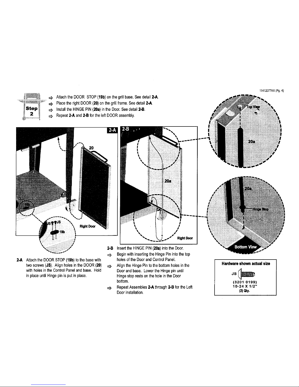
Attachthe DOOR STOP(191))on the grill base.See detail2-A.
Placethe right DOOR(20)onthe gdti frame.Seedetail 2-A
=_ Installthe HINGE PIN(20a)in the Door.Seedetail 2-B
=_ Repeat2-A and 2-Bfor the leftDOORassembly.
11412077AX(Pg.4)
20
I
RightDoor
2-A AttachtheDOORSTOP(19b) to the basewith
two screws(J$), Alignholesin the DOOR(20)
with holesin the ControlPaneland base. Hold
in placeuntil Hingepin is putin place.
2-B Insert the HINGE PIN (20a) into the Door,
c:_ Begin with insertingthe Hinge Pin into the top
holes of the Door and Control Panel.
Align the Hinge Pinto the bottom holes in the
Door and base_ Lower the Hinge pinuntil
Hinge stop rests on the hole inthe Door
bottom.
Repeat Assembles 2-A through2-B for the Left
Door installation.
Hardware shown actual size
(3201 0199)
10-24 X tl2"
(2)Qty.
Page 5
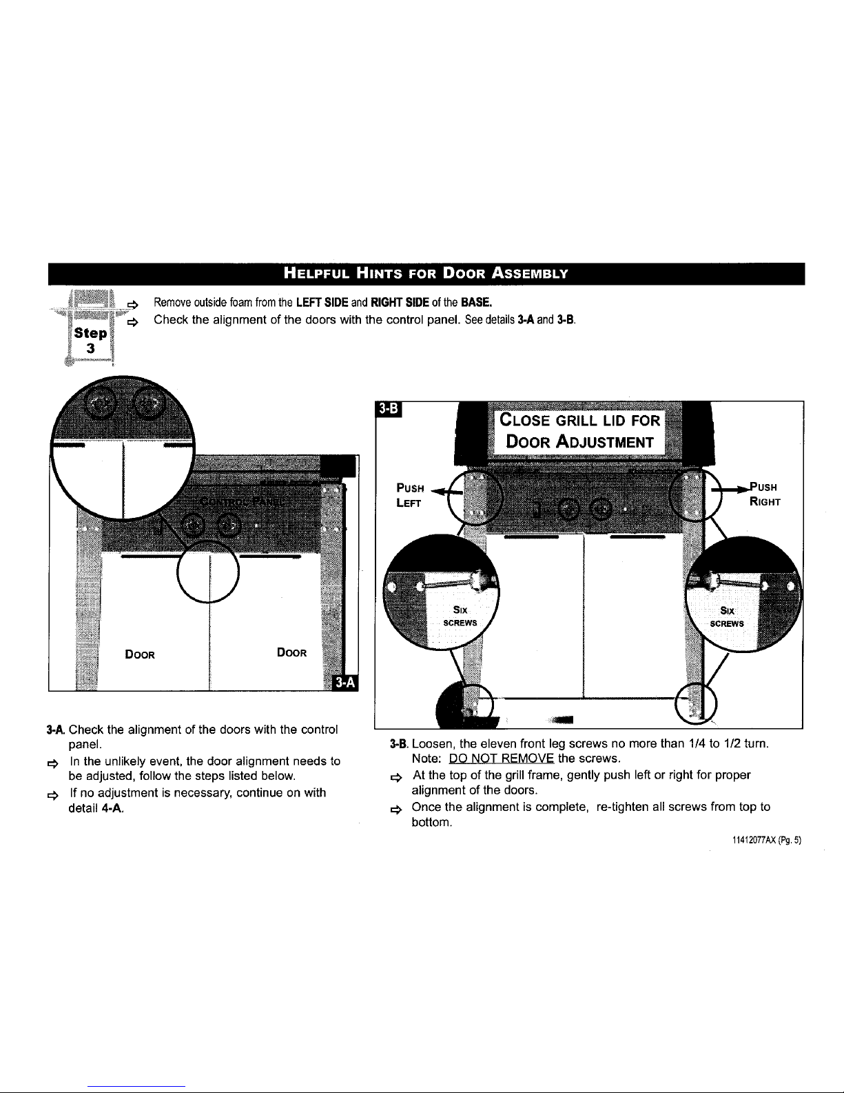
Removeoutsidefoamfromthe LEFTSIDE andRIGHT SIDEof the BASE.
Check the alignment of the doors with the control panel. Seedetails3-Aand 3-B.
DOOR DOOR
3-A. Check the alignment of the doors with the control
panel.
=_ In the unlikely event, the door alignment needs to
be adjusted, follow the steps listed below.
If no adjustment is necessary, continue on with
detail 4-A.
CLOSE GRILL LID FOR
DOOR ADJUSTMENT
PUSH
LEFT
3-B. Loosen, the eleven front leg screws no more than 1/4 to 1/2 turn.
Note: DO NOT REMOVE the screws.
=_ At the top of the grillframe, gently push left or right for proper
alignment of the doors.
=_ Once the alignment is complete, re-tighten all screws from top to
bottom.
114_2077AX(Pg.5)
Page 6
11412077AX(Pg.6)
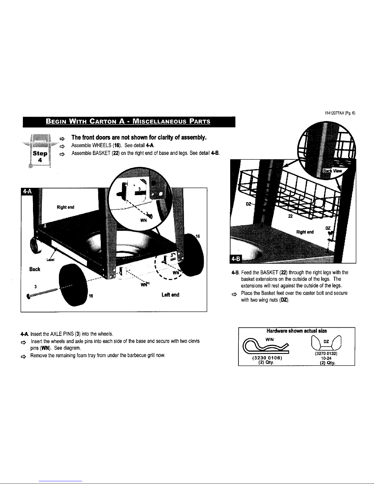
The front doors are not shown for clarity of assembly.
=:> AssembleWHEELS(16). Seedetail 4-A.
<> AssembleBASKET(22)on the right endof baseand legs,Seedetair4-B.
Back
3
Label
Legend
4-B Feedthe BASKET(22)throughtherightlegs with the
basketextensionson the outsideof the legs, The
extensionswill rest againstthe outsideof the legs.
=:> Placethe Basketfeet over the caster boltandsecure
with twowing nuts(DZ).
4-A. InserttheAXLEPINS(3)into thewheels.
=:> Insertthe wheelsand axle pins intoeachside of thebaseand securewith twoclevis
pins(WN). Seediagram.
Removetheremainingfoamtrayfrom underthe barbecuegrill now.
Hardwareshownactualsize
(3230 0106)
(2) Qty.
(3270 0132)
10-24
(2)Qty.
Page 7

_, Assemblethe twoGREASE DRIPPANS(48) underthebottomcastingand
securewith the two GREASEPANHANGERS(49).See detailS-A
48
49
BACKOFGRILL,UNDERNEA'ITIVIEW
I
I
t
%
49
VIEW SHOWNWITHOUTTHE SIDE PANELFORCLARITYOF ASSEMBLY
48
\ FRONT
J
48 ...... /
49
S-A Align theholes inthe GREASEPAN(48)with the holesunderneath
theBottomcasting. Securethe GreasePan to the bottomcasting
with a GREASEPANHANGER(49). Repeatthe assemblyforthe
other GREASEPANandGREASEPANHANGER
11412077AX(Pg,7)
Page 8

Assemblethe two DISPOSABLEGREASEPANS(48a).See detail6-A.
11412077AX(Pg.8)
BACK OF GRILLUNDERNEATHVIEW
48a
6.A. Placetwo DISPOSABLEGREASEPANS(48a)
intotheGreasePanHangersas shown.
Page 9

AssembleCONTROLKNOBS(32),MEATPROBERECEPTACLE(57a)andMEATPROBE(57)indetail7-A.
AssemblePERFORATEDSTAINLESSTENT(62). Seedetail 7-B.
7-A.Place CONTROLKNOBS(32)on valve stems.
InsertMEATPROBERECEPTACLE(57a) into the rightsideof the
controlpanel.
=_ Placethe MEATPROBE(57) intothe meat probereceptable.
7-B. PlacethePERFORATEDSTAINLESSTENT(62) in
theslots of the PORCELAIN'T' TENT(61).
11412077AX(Pg.9)
Page 10

=_
Step
AssembleFRONTHANDLEAssemblytothe GRILLLID(55) in detail8-A.
AssembleCOOKINGGRIDS(63)and WARMINGRACK(65). See detail8-B.
11412077AX(Pg.10)
58
60
AO AO
8-A The FRONTHANDLE(58),HANDLESPACER(60), HANDLE
INSULATOR(59), fourscrews(Dr) andfour hex nuts(AO) are
PRE-ASSEMBLEDatthe factory.
=_ Removethe four hex nuts(AO) from the Handleassembly.
Insertthescrewsin the Handleassemblyinto theGRILL LID(55)
and securewith four hex nuts(AO).
,=# Tightenwithadjustablewrenchor7/16"wrench.
II
8-B. Placethe COOKINGGRIDS(63)in the Bottomcasting
with the smoothsurfacedown.
Setthe WARMINGRACK(65) nearthe backof the bottom
casting.
Hardwareshownactualsize
(00401e36)
1/4"-20 x 1 1/4" 1/4-20
(4) Qty. (4) Qty.
Page 11

_Step_
,=# AssemblePre-AssembledRIGHTSIDETABLEindetail9-A.
Note:Useboth handsand lift with side tablebrackets.NEVERlift with plasticparts.
PRE-ASSEMBLED
SIDETABLE
Right
9-A.Use the 6-lobescrewdriverto back outthe outside screwslocatedin
thetop rightlegs (2 or 3 turns)just enoughfor the SIDEBRACKETS
(11and 13) on the PRE-ASSEMBLEDsidetable,to slide inplace.
CAUTION: DO NOTRemovescrewscompletely.
=_ Placethe bottomslot of the bracketsonthescrewsfirst andthenthe
topslot.Note:The TOOLBAR (12)facesthe front ofthe grill.
=_ GentlyslidetheBracketdownandtightenscrews.
11412077AX(Pg.11)
Page 12

11412077AX(Pg,12)
AssemblePre-AssembledLEFT SIDETABLEindetail 10-A
=:> Note:Use bothhandsand liftwithsidetablebrackets.NEVERlift with plasticparts.
PRE-ASSEMBLED
SIDETABLE
Left
Front
10-A.Usethe6-lobescrewdriverto backout the outsidescrewslocatedin the top
leftlegs (2 or 3 turns)just enoughfor the SIDEBRACKETS(11and 13) on
the PRE-ASSEMBLEDsidetable,toslide in place.
CAUTION: DONOT Removescrews completely.
=_ Placethe bottomslot of the bracketson thescrewsfirst and thenthe topslot.
Note:TheTOOLBAR(12) facesthe frontof the grill.
=:> GentlyslidetheBracketdownandtightenscrews.
Page 13

AssembletheELECTRODEWIRES(29),SWITCHWIRES(26)andthe9-VOLTBATTERY
(30)totheELECTRONICMODULE(28)indetails11-A.
AssembletheELECTRONICMODULE(28)undertheLeftSideTableindetail11-B.
11412077AX(Pg.13)
ELECTRONICMODULE
ili_;1
9-VOLT BATTERY3,0
ELECTRONICMODULE28
\
\
MAIN.,
BURNER
ORANGE
:LECTRODE
WIRE29
SWITCHWIRES26-':ZI
(BLACKWIRESWITHRED
FLAGCONNECTERS)
BURNER
ORANGE
ELECTRODE
WIRE29
TESTTHE IGNITER: A SPARKSHOULDAPPEAR
AT ELECTRODETIP.
IF THE SPARKDOES NOTAPPEAR:
CHECK THE WIRECONNECTIONSTO THE
MODULE.
CHECK PROPERASSEMBLYOF FRESH9-VOLT
BATTERY.
LEFT SIDE OF GRILL
11-A. Attachthe blackSWITCHWIRES (28),with
thered connecterslocatedon the left sideof
yourgrill, tothe two large pinson the
ELECTRONICMODULE(28), Thenattach
thetwoorange ELECTRODEWIRES(29)
locatedon the left side of yourgrill, to the
pinson the modulemarked1MBand 2MB.
Insertthe 9-VOLTBATTERY(30)inthe
module,it MUSTsnap in place.
/_ Caution: Insurethatthe wires DONOT
touchhot surfacessuchasthegrill
casting.
Hardwareshownactualsize
JS(_
(3201 0199)
10-24 X 112"
(2) Qty.
JS
Left front
side of
grill
11-B, Onthe LEFTsideof thegrill, locatethefront
SIDEBRACKET(13)andattachthe
ELECTRONICMODULE(28)underneaththe
frontbracketflange inthe holesindicatedin
the MountingHolesdetail,withtwoscrews
(JS).
=_ Bundleextrawirelengthwith wiretie (LA) not
shown.
Mounting Holes Detail
Side Frame
Inside
Outside
Tool Bar Top View of Bracket (13) Tool Bar
Page 14

Assemblethe CYLINDER(79)tothe Cylindercaddy.Seedetail12.A.
Placethe CYLINDERRETAINERWIRE(77)over the CylinderCollar.Seedetail 12-B
AttachingTYPE 1fi_ng to the fuel outletvalvein detail12-C
12-A Set CYLINDER(79)in the cylindercaddywith
theoutletvalve facingthe frontof the grill
IMPORTANT!
TO ENSURE PROPER GAS FLOW, BURNER
CONTROL VALVES MUST BE "OFF" BEFORE
OPENING THE GAS CYLINDER VALVE.
77
Leffend
12-B Placethe CYLINDERRETAINERWIRE (77)
overthe Cylindercollar,byrotatingthe wire
fromthe originalpositiontowardthe cylinder
collar.
/_ WARNING: Duringassemblyof
grilland whenattachingor replacingthe
L.P.gas cylinder,insurethat the gas
supplyhoseis free of Idnksand/or
damageandis at least 3" away fromhot
surfacessuchas the grill casUng.
27
79
12-C InserttheTYPE 1 nippleof the regulator(27)
intothecylinder'sfuel valveoutletasshown.
Turntheregulatorhandwheelclockwiseto
tighten,Notoolsare needed. TheHand
wheelwillcometo a completestopwhenthe
connectionissecure and gaswillnotflowuntil
a positiveseal isachieved.
11412077AX{Pg.14)
Page 15

11412077AX(Pg.15)
Attachthe SideBurnerassemblytothe grillin detail 13.A
c_ Assemblethe SIDEBURNERELECTRODEwith wires (8) in detail13-B,
Note:Usebothhandsandlift with side table brackets.NEVERlift withplasticparts.
Left
Top View
6-LOBE
SCREWDRIVER ,
13-A.Usethe 6-lobe screwdriverto back out the outside screws
locatedin the top left legs (2 or 3 turns) just enough for the
SIDEBRACKETS(11and13) on the PRE-ASSEMBLEDside
burner,to slidein place.
CAUTION: DO NOT Removescrewscompletely.
Placethe bottomslot of the bracketson the screws first and
thenthe top slot.Note:The TOOLBAR(12) facesthe front of
thegrill.
GenlJyslidetheBracketdownandtightenscrews.
13-B.ThreadtheblueSIDEBURNERELECTRODE
wires (8)through the Baseandsecurethe Double
electrodeto the base with onescrew(JS).
Hardwareshownactualsize
(3201 01991
10-24 X tl2"
(1) aty,
Page 16

;i__,:.._.-_ =# Assemblethe IGNITERWIRES(lead ELECTRODEWIRES(29)and Side burnerwires),SWITCHWIRES (26)andthe 9-VOLT
BATTERY(30)in details 14-A.
Assemblethe ELECTRONICMODULE(28) indetail 14-B.
ELECTRONIC MODULE
9-VOLTBATTERY_[0
ELECTRONIC
MODULE28
\
WIRE29
GLUE
StDE
3URNER
ECTRODE
WIRES
26
TEST THE iGNITER: A SPARKSHOULDAPPEAR
AT ELECTRODETIP.
iF THE SPARKDOESNOT APPEAR:
CHECK THEWIRECONNECTIONSTO THE
MODULE.
CHECK PROPERASSEMBLYOF FRESH9-
VOLTBATTERY.
LEFT SIDE OF GRILL
14-A.Attach the blackSWITCHWIRES(26),withthe
red connecterslocatedon the left sideof your
grill,to the twolargepinson the ELECTRONIC
MODULE(28).Thenattachthetwo orange
leadELECTRODEWIRES (29)to the pinson
themodulemarked1MBand2MB andthetwo
blueSide BurnerElectrodewirestothe pinson
the modulemarked1SBand 2SB.
_, Insertthe 9-VOLTBATTERY(30)in the
module,it MUSTsnap in place.
/_, Caution: Insurethatthe wires DO NOT
touch hotsurfacessuch asthegrillcasting.
Hardwareshown actual size
(3201 0199)
10-24 X 112"
(2) Qty.
28 Left front
side of
grill
14-B.Locatethefront SIDE BRACKET(13)and
attachtheELECTRONICMODULE(28)
underneaththefront bracketflange in the
holesindicatedwithtwo screws(,IS).
=_ Bundleextra wirelengthwithwiretie (I.A) not
shown.
Mounting Holes Detail
Frame Side Frame
Module
Outside
Tool Bar Top View of Bracket (13) Tool Bar
11412077AX(Pg.16)
Page 17

Step
151
11412077AX(Pg.17)
Assemblethe SIDEBURNERVALVE(27)in detail 15-A.
Assemblethe SIDEBURNERGRID(41)and the SIDE BURNERCONTROLKNOB(40)onto theSide burner.See detail15-B.
HA
HA
! I!
! I!
15-A.AttachtheSIDEBURNERVALVE(27)(locatedon
theHoseNalve/Regulatorassemblyattachto the
controlpanel)to the BASEwith two screws(HA).
Note:the Side burnerhosemustbe thread between
theleftlegs,not in front oftheleft leg.
Z_ WARNING: The orificemustbe insidethe
venturitube.
Hardwareshownactualsize
(3250 0105)
#e-32 x 3/8"
(2) Qty.
15-B. Set the SIDE BURNER GRID (41) tabs into
the slots on the Side Burner base and turn
the grid until it stops. Note: Before each use
turn the Side Burner grid to insure that it is
secure.
=:_ Push the SIDE BURNER CONTROL KNOB
(40) ontothe Side BurnerValve stem.
Page 18

Assemblethe CYLINDER(79)to the Cylindercaddy.See detail16.A
Placethe CYLINDERRETAINERWIRE(77)over the CylinderCollar.Seedetail 16.B
AttachingTYPE1 fittingto the fueloutlet valvein detail 16-C.
16.A SetCYLINDER(79)inthe cylindercaddy
with the outletvalvefacingthefront of the
grill.
IMPORTANT!
To ENSURE PROPER GAS FLOW, BURNER
CONTROL VALVES MUST BE "OFF" BEFORE
OPENING THE GAS CYLINDER VALVE,
16-B Placethe CYLINDERRETAINERWIRE(77)
overthe Cylinder collar,by rotatingthewire
fromthe originalpositiontowardthe cylinder
collar.
/_ WARNING: Durtngassemblyof
grillandwhenattachingor replacingthe
L.P.gas cylinder,insurethat the gas
supplyhose is freeof kinksand/or
damageand is at least3" awayfrom hot
surfacessuch as the grill casting.
16-C Insertthe TYPE1 nippleofthe regulator(27)
intothecylinder'sfuel valveoutlet as shown.
Turntheregulatorhandwheelclockwiseto
tighten.Notoolsareneeded. The Hand
wheelwillcometoa completestopwhenthe
connectionissecureandgaswillnotflowuntil
a positiveseal is achieved.
11412077AX(Pg.18)
Page 19

COLEMAN GAS BARBECUE GRILL WARRANTY
CASTINGS - LIMITED LIFETIME
BURNER - LIMITED FIVE {5_ YEARS
OTHER PARTS - LIMITED ONE (t_ YEAR
TheColemanCompany,Inc.("Coleman")warrantsthatfortheperiodthatyouownthisproduct,itwillbefreefromdefectsin
materialandworkmanship.Thiswarrantyappliestothe followingpadsfor the followingtimepedods: thecastingsare
warrantedforLIFETIMEagainstbumthrough;theburneriswarrantedforfive(5)years;andotherpadsarewarrantedforone
1)year,exceptthepropanecylinderandpaintfinish.WeDONOTWARRANTinanywaythepropanecylinder(seelabel
oncylinderforcylindermanufacturer'swarranty)orthepaintfinishoftheproduct.Coleman,atitsoption,willrepairorreplace
thisproductor anycomponentof the productfoundtobe defectiveduringthewarrantyperiod.Replacementwill bemade
witha neworremanufacturedproductorcomponent.Ifthe productisnolongeravailable,replacementmaybemadewitha
similarproductof equalorgreatervalue.Thisisyourexclusivewarranty.
Thiswarrantyisvalidfor theoriginalretailpurchaserfromthedateof initialretailpurchaseandis nottransferable.Keepthe
originalsalesreceipt.Proofof purchaseis requiredto obtainwarrantyperformance.Colemandealers,servicecenters,or
retailstoressellingColemanproductsdonothavethe dghtto alter,modifyor anywaychangethetermsandconditionsofthis
warranty.
Thiswarrantydoesnotcovernormalwearof partsordamageresultingfromanyofthefollowing:negligentuseor misuseof
theproduct,useonimpropervoltageorcurrent,usecontrarytotheoperatinginstructions,disassembly,repairoralterationby
anyoneotherthanColemanoranauthonzedservicecenter.Further,thewarrantydoesnotcoverActsof God,suchasfire,
flood,hurricanesandtornadoes.
Colemanshallnot be liableforany incidentalorconsequentialdamagescausedbythe breachof anyexpressorimplied
warranty.Exceptto theextentprohibitedbyapplicablelaw,anyimpliedwarrantyofmerchantabilityor fitnessforaparticular
purposeis limitedindurationto thedurationofthe abovewarranty. Somestates,provincesor urisdictionsdonotallowthe
exclusionor limitationof incidentalor consequentialdamagesor limitationson howlongan impliedwarrantylasts,sothe
abovelimitationsorexclusionmaynotapplytoyou. Thiswarrantygivesyouspecificlegalrights,andyoumayalsohaveother
rightsthatvaryfromstatetostateorprovinceto province.
DONOT RETURNTHISPRODUCTTOTHEPLACEOF PURCHASE.
Taketheproductto an authorizedColemanservicecenter.YoucanfindthenearestauthodzedColemanservicecenterby
calling1-800-356-3612.If a servicecenteris notconvenientlylocated,youmaycall thesamenumberforinstructionson
shippingtheproducttotheColemanCompany,Inc.Youmayalsocallthesamenumberif youhaveanyquestionsconcerning
thiswarranty.
NOTVALID IN MEXICO. j
ForWARRANTY,SERVICeand PARTS
Locateyourmodelnumberand serialnumberonthelabel foundon thebackofyourgrillbase.
CARE OF STAINLESS STEEL PAR're
BEFOREcleaninganypartof IJlegrill,allowthegdll to cooldowncompletely.
:€ Cleanthe grill with anymultipurposemetalpolishor stainlesspolish, low in abrasiveandwith no phosphorus
inge_lients.(Readcleanerlabelsforsuggestedusesand directionson properuseof thecleaner.)
:_ Usea softclothor spongetopreventscratchesandmarringofthe stalnleassteelsurfaces.
:_ NEVERUSEOVENCLEANERS.
:€ To protectthe integrityofyourgrillagainsttheeffectsof theenvironment,usea grill coverwhenthe grill is not
inuse.
=€ FaUureto comply withtheowner'sUSE& CAREMANUALINSTRUCTIONS&ASSEMBLYINSTRUCTIONScanvoid
rightofwarranty.
11412077AX(Pg,19)
BEFORE USING YOUR GRILL
READ OWNER'S USE AND CARE MANUAL:
O For properfillingand purgingof thecylinder
n For leaktestingallgassupplyconnections
O For correctgrilllightinginstructions
n For use and storageof the grilland cylinder
Z_WARNING! The edges of sheet metal parts can
causeinjury ifnot handledwith care.
LL_
/_WARNING! WHEN LEAK TESTING:
DO NOTsmoke.
DONOT usefire to testfor leaks.
DANGER:
NEVERstore a spare LP gas supply cylinderunderthe
grill bodynor insidegrill enclosureto avoidthepossibility
ofan explosion. Referto the Useand Care manual.
/ik IMPORTANT:
Be sure to tighten up all hardware(screws, nuts, bolts,
etc.)at least oncea year or eachgrillingseason.
Leaktestgassupplyconnectionsoutdoorsas
indicatedby arrows.
®
 Loading...