

Page 1
Installation Instructions
for Loop CPU holder
CPU/012
500
240
Allen
Key
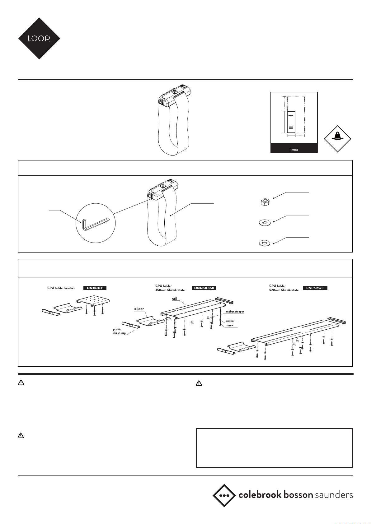
CPU DESK FITTING SUPPLIED SEPERATELY
80
225
Min/Max CPU Dimensions
CPU/012PARTS INCLUDED:
M8
Locknut
Loop CPU
Holder
Keyed metal
washer
Nylon
washer
MAX
2
B
0
L
K
1
.
G
4
/
4
WARNING
• Ensure desk is suitable to take the weight of the CPU holder and CPU.
• Do not use this product for any purpose other than that for which it was designed.
• Hold the CPU tightly when making adjustments.
• Care should be taken to avoid trapping ngers.
• Do not dismantle or modify the CPU cradle.
• Supported weight must not exceed 20kg (44.1lb) per cradle.
MAINTENANCE AND INSPECTION
• Ensure all screws and xings are fully tightened and occasionally re-tighten if necessary.
• Clean with a dampcloth. DO NOT use solvents.
CPU-012-INST-B-SEPT 2017
DISCLAIMER
• The use of power tools, lever bars or excessive force during the installation, or
reconguration of the product will invalidate your guarantee.
• Failure to observe the recommendations in the use, and conguration of these products
may aect your guarantee.
• As part of Colebrook Bosson Saunders ongoing product improvement programme, the
design of products may change without prior notice and details may vary from those illustrated.
PATENTS
Colebrook Bosson Saunders hold a number of patents and other
intellectual property rights covering our products and processes.
You can nd patent information on our website at:
www.colebrookbossonsaunders.com/patents
Page 2
1
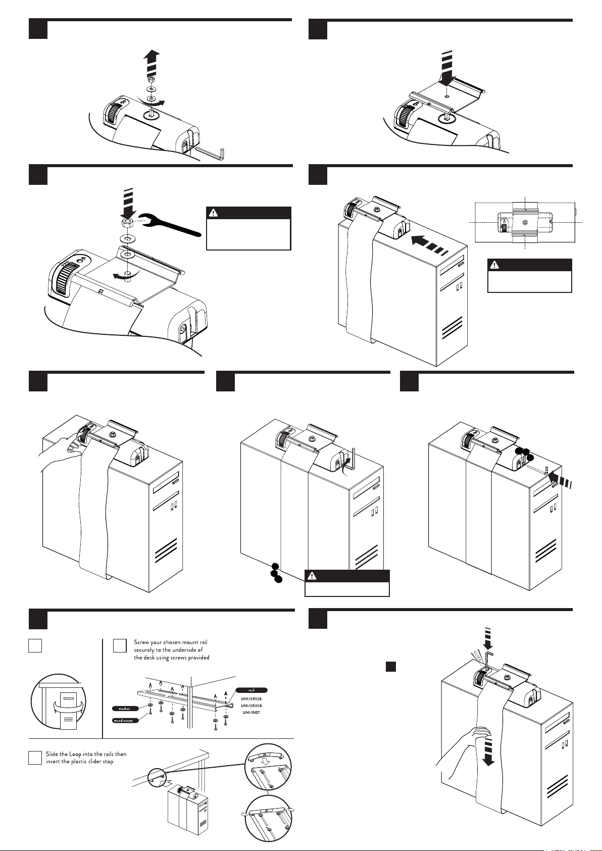
REMOVE ALLEN KEY, NUT AND WASHERS
FROM LOOP CPU HOLDER
2
TAKE SLIDER FROM CPU FIXING KIT
(ORDERED SEPERATELY) AND FIT INTO POSITION
3
TIGHTEN WASHER AND LOCK NUT ONTO PIN
IMPORTANT NOTE
Ensure nut is fully tightened
(6nm recommended
minimum torque)
5
ROLL RATCHET WHEEL
TO TIGHTEN STRAP TO CPU
6
ADDITIONAL TIGHTENING
REQUIRED USING ALLEN
KEY PROVIDED
4
SLIDE CPU INTO THE LOOP
7
PLACE ALLEN KEY INTO
STORAGE HOLE
IMPORTANT NOTE
Moulding should be positioned
in the centre of the CPU
8
MOUNTING CPU FIXING KIT TO DESK
Make sure the CPU
8A 8B
will be able to rotate
from side to side
8C
IMPORTANT NOTE
Ensure strap is fully tightened
9
[OPTIONAL] TO REMOVE LOOP
Unmount CPU from desk following
reverse procedure from step 8c
Use tool to push down on release button
and hold whilst pulling strap downwards
 Loading...