

Cold Shot Chillers ACWC-180-EM-DR-LT-0-5 Installation, Operation And Maintenance Instructions
INSTALLATION, OPERATION, AND
MAINTENANCE INSTRUCTIONS
(ACWC-240-E model shown)
AIR-COOLED WATER CHILLERS
ACWC-120 through - 240 MODELS
2730 Maximilian Dr., Houston, Texas 77032 • Phone (800) 473-9178, (281) 227-8400
Fax (800) 473-9175, (281) 227-8404 • www.waterchillers.com
Marrone & Co., Inc.

MODEL NUMBER NOMENCLATURE
Example Model#:
ACWC
-
60 - E - ST - LT - 40 - 5
Position:
1 2 3 4 5 6 7
Position-Description
1. Model Type: ACWC=AirCooledWaterChiller, WCWC=WaterCooledWaterChiller, etc.
2. Nominal Capacity in kBtu/hr
3. Series System: various
4. Flow Design: (_=Portable, ST=Stationary, RF=ReverseFlow, EXCH=HeatExchanger, DP=DualPump,
DR=DualReturn)
5. Leaving Fluid Temperature (_=Standard, LT=LowTemperature-specify lowest temperature in °F)
6. Ambient Temperature Conditions:
a. IND: Indoor use only. Casters, typically on frame.
b. 40: Suitable for outdoor use with an ambient of 40
c. 0: Suitable for outdoor use to 0°F ambient. Includes low ambient fan control. Casters, optional.
d. M20: Suitable for outdoor use to -20°F ambient. Hot Gas Bypass and/or Wind Baffles may be included. Casters,
optional.
°F ambient. Casters, optional.
7. Electrical Power (See specification sheet)
(Variations of the above nomenclature exist and may not include every description).
TABLE OF CONTENTS
I. IMPORTANT .................................................................................................................................................................................................................... 3
A. CODES AND REGULATIONS ........................................................................................................................................................................................... 3
B. INSPECTION .................................................................................................................................................................................................................. 3
C. SAFETY CONSIDERATIONS ............................................................................................................................................................................................. 3
D. REPLACEMENT PARTS ................................................................................................................................................................................................... 3
II. INSTALLATION ................................................................................................................................................................................................................ 4
A. MOVEMENT/RIGGING .................................................................................................................................................................................................. 4
B. PLACEMENT .................................................................................................................................................................................................................. 4
C. MOUNTING ................................................................................................................................................................................................................... 4
D. SPLIT SYSTEMS (Remote Condenser or Condensing Unit) ............................................................................................................................................ 5
E. ELECTRICAL POWER AND CONNECTIONS ...................................................................................................................................................................... 5
F. FREEZE PROTECTION ..................................................................................................................................................................................................... 6
G. GLYCOL ......................................................................................................................................................................................................................... 6
H. PERFORMANCE ............................................................................................................................................................................................................. 7
III. PRE-STARTUP ................................................................................................................................................................................................................ 8
IV. STARTUP ....................................................................................................................................................................................................................... 9
V. SYSTEM COMPONENTS: (See your chiller’s specification for details.) ......................................................................................................................... 10
VI. MAINTENANCE (BASIC GUIDE).................................................................................................................................................................................... 13
VII. TROUBLESHOOTING (BASIC GUIDE) ........................................................................................................................................................................... 15
VIII. APPENDIX ................................................................................................................................................................................................................. 18
MNL_Standard-Basic_ACWC-24to240-E-(IN PROGRESS)_(0815).docx - 2 -

I. IMPORTANT
A. CODES AND REGULATIONS
The United States Environmental Protection Agency (EPA) has issued various regulations
regarding the introduction and disposal of refrigerants in this unit. Failure to follow these regulations
may harm the environment and can lead to the imposition of substantial fines. Because these
regulations may vary due to the passage of new laws we suggest that, any work on this unit be done
by a certified technician. Should you have any questions, please contact the local office of the EPA.
This product is designed and manufactured to permit installation in accordance with National
Codes. It is the installer’s responsibility to install the product in accordance with National Codes
and/or prevailing local codes and regulations. The manufacturer assumes no responsibility for
equipment installed in violation of any codes or regulations.
IMPORTANT MESSAGE TO OWNER:
These instructions should be carefully read and kept near the product, for future reference. While
these instructions are addressed primarily to the installer, useful maintenance information is
included. To insure proper set up, operation, and performance it is recommended that a licensed
service professional start this piece of equipment. Have your installer acquaint you with the
operating characteristics of the product and periodic maintenance requirements.
B. INSPECTION
This product has been inspected at the factory and released to the transportation agency without
known damage. Inspect carton’s exterior for evidence of rough handling in shipment. Carefully
remove protective wrap and all banding to uncrate, for inspection; if damage is found, report
immediately to the transportation agency and Cold Shot Chillers. Provide a report and photographs
(highly recommended), if possible.
Once it is established that the unit has positive pressure, proceed to installation. Test the system
service valves with refrigeration gauges to ensure refrigerant pressure is present and no
undetectable damage (i.e. dropping the unit) has occurred, when possible.
C. SAFETY CONSIDERATIONS
Installation, start-up, and servicing of this equipment can be hazardous due to system pressures,
electrical components, and equipment location (roofs, elevated structures, etc.) Only trained,
qualified installers and service mechanics should install, start up, and service this equipment. When
working on the equipment, observe precautions in the literature, tags, stickers, and labels attached
to the equipment, and any other safety precautions that apply.
• Follow all safety codes.
• Wear safety glasses and work gloves.
• Use care in handling, rigging, and setting bulky equipment.
• Use care in handling electronic components.
D. REPLACEMENT PARTS
• For information on replacement parts, contact Cold Shot Chillers.
• When ordering parts, provide complete model and serial number as shown on the unit nameplate.
• Most parts will be available through local distributors.
MNL_Standard-Basic_ACWC-24to240-E-(IN PROGRESS)_(0815).docx - 3 -
II. INSTALLATION
A. MOVEMENT/RIGGING
1. The preferred method for movement of the chiller while on the pallet is with forklift or pallet jack.
2. For rigging, overhead rigging with spreader bars above the unit is preferred. Protect unit from being crushed.
CAUTION! All panels must be in place when rigging. Failure to follow these requirements could result in personal
injury or equipment damage.
3. Maneuvering of the system must be done with care to prevent damage to the panels or the internal components
mounting.
4. See specification sheets for physical data and unit dimensions.
B. PLACEMENT
1. Select a location for air-cooled units with adequate air circulation that is as dust free as possible.
2. There must be a minimum of 3 ft of space for service and for unrestricted airflow on all sides of unit, and a
minimum of 8 ft clear air space above unit. Select a location where air is not recirculated back into condenser.
For multiple units, allow additional separation between units for airflow and service.
3. Verify ambient conditions that the system is suitable.
a) IND - Indoor units are suitable for indoor use only. No wet environments.
b) 40 - Outdoor units to 40°F (same as above) and are suitable for outdoors to 40°F ambient temperature
and suitable for wet environments.
c) 0 - Outdoor units to 0°F (same as above) and suitable for outdoors to 0°F ambient temperature.
d) M20 - Outdoor units to -20°F (same as above) and suitable for outdoors to -20°F ambient temperature.
4. Avoid environments which may be corrosive to the chiller, unless properly treated.
5. Avoid locations that may have direct spray such as from roof edges or sprinklers.
6. Select location as near to the process as possible to reduce the system piping / pressure drop.
C. MOUNTING
1. Level the unit to ensure proper oil return to compressors and fluid draining.
2. When unit is in proper location, secure unit to foundation or on vibration isolators, as needed/required by local
requirements. Fasteners for mounting unit are field supplied.
3. PIPING
a) Connect piping or hoses to unit, making sure that the inside diameter (I.D.) of the pipe or hose is the
same as or greater than unit connections and that the material is designed for the expected fluid
conditions. Reverse Flow designs will require proper pipe size suction piping to ensure the pump
maintains appropriate Net Positive Suction Head (NPSH). Most pumps are not self-priming.
b) The fluid circuits must contain a bypass to prevent a “dead head” condition for the pump and to allow
return process water to chiller tank. A bypass valve is required in the system to ensure proper flow
through the evaporator and to provide adjustment of the pressure and flow to the process.
(1) Refer to the system Flow Diagram for details, or to the actual unit.
c) Typical Chiller Fluid Flow Designs:
(1) Stationary
(2) Reverse Flow: Chilling system with evaporator and circulating pump.
(3) Portable: Chilling system with evaporator, circulating pump, and reservoir tank with bypass.
(4) Extra Heat Exchanger: Same as Portable along with an extra chilled fluid heat exchanger.
(5) Dual Pump: Same as Portable and includes a second pump typically for process use.
(6) Dual Return: Same as Portable yet includes a second return direct to tank for some flow.
d) System Recommendations:
(1) Valves installed throughout the system, as needed. Typical at each load for isolation and
flow/pressure balancing purposes through system.
(2) Use low pressure drop design components. (Such as long radius 90s or 45s elbows)
(3) Add piping and valve to the tank drain port.
(4) Temperature and pressure gauges throughout system at ideal locations for monitoring.
: Chilling system with evaporator.
MNL_Standard-Basic_ACWC-24to240-E-(IN PROGRESS)_(0815).docx - 4 -

(5) Vent and drain valves to provide ability to bleed air and drain fluids from system, as needed.
(6) Heat-trace cable. Protect any fluid system exposed to freezing ambient conditions.
e) Systems with the process piping located above the chiller, should be aware of possible fluid returning to
the chiller when the system is turned off. Typically, the chiller inlet/outlet piping is below the tank
water level which will limit draining fluid to tank, however if the process piping is opened, the fluid may
return to the tank and overflow. Recommend isolation valves be installed on the inlet and outlet
piping.
4. ACCESSORIES/ OPTIONS/EXTRA EQUIPMENT
a) Any additional accessories, options, or equipment must be installed as necessary before the system is
started. Refer to the accessory literature for installation instructions, as applicable.
b) Wiring connections for field-supplied equipment are shown on wiring diagrams.
D. SPLIT SYSTEMS (Remote Condenser or Condensing Unit)
1. Conform to all local codes and standard practices for systems with refrigerant.
2. Systems with split refrigerant systems are typically shipped without refrigerant, however, are it is charged with
nitrogen to maintain a positive pressure (typically 10-15 psi).
3. Verify and remove the nitrogen charge. Each marked section should have a positive charge (see tag/decal noted
at connection point).
a) If no pressure is present, reapply pressure and check for leaks before charging with refrigerant.
4. Pipe the refrigerant lines of the two units together as required.
5. Pressure test the system, pull vacuum, and degas. Use proper industry practices with system.
a) Split systems need to be evacuated prior to charging with refrigerant.
6. Add refrigerant to the liquid line service port. See the equipment label plate for the type of refrigerant and
typical amount of initial charge or check the specification sheet. Adjust as needed to set the appropriate charge
as noted in Startup section-Refrigerant Charge.
E. ELECTRICAL POWER AND CONNECTIONS
1
1. POWER SUPPLY: Field wiring must comply with national and local codes.
a) Install a branch circuit fused disconnect of adequate size to handle starting current. The disconnect must
be within sight from the unit and readily accessible, in compliance with National Electrical Code (NEC),
Section 440-14.
b) Verify electrical power on the Cold Shot Chillers label plate with actual voltage.
c) Connect line power supply to terminal block or as noted in machine; typically, connect power leads to
terminals L1, L2 and L3 on compressor contactor.
d) Ensure Ground wire is connected appropriately.
e) 208/230V/3Ø systems with high or “stinger” leg, connect this leg to L2 or middle terminal. Failure to do
so will cause early control component malfunction.
(1) If 208V, verify that the control circuit voltage out of the transformer is the proper amount. If not,
check the transformer for additional tap wires for changing to 208V, when available.
2. Verify that the chiller selector switch is in “OFF” position before applying power.
3. ROTATION (3-PHASE)
If using a phase sequence tester, electrical phase direction is clockwise (A-B-C).
1
Electrical Notes:
• Factory wiring is in compliance with NEC. Any field modifications or additions must be in compliance with all applicable codes. Use copper,
copper-clad aluminum for field power supply only.
• Field power supply wiring must be 75 C minimum.
• If any of the original wiring furnished must be replaced, it must be replaced with 90 C wire or its equivalent.
• Compressor thermally protected. Three-phase motors are protected against primary single-phasing condition.
• 60 Hz units have 120 volt control circuit. 50 Hz units have 230 volt control circuit. A separate source of supply at the correct voltage
• Must be field supplied through a fused disconnect device with a maximum rating of 15 A to TB2 connections L1 (Hot Side) and L2 (Neutral).
• Open control circuit disconnect switch for servicing only. Disconnect must remain closed for crankcase heater to operate.
• Transformers must be fused and grounded per applicable codes.
MNL_Standard-Basic_ACWC-24to240-E-(IN PROGRESS)_(0815).docx - 5 -
4. IMPORTANT: Allowing the unit to operate with a voltage imbalance in excess of 2% may void the warranty.
% Voltage Imbalance = 100 x (max voltage deviation from avg voltage) / (avg voltage)
Determine maximum deviation from average voltage:
MAXIMUM DEVIATION:
AVERAGE VOLTAGE:
• Determine % voltage imbalance:
• This amount of phase imbalance is Satisfactory as it is below the maximum allowable 2%.
IMPORTANT!!
WRITTEN APPROVAL FROM COLD SHOT CHILLERS, OTHERWISE ALL WARRANTIES WILL BECOME VOID.
Example: Expected supply voltage to unit is 240-3-60.
AB = 243A – 239B = 4 volts*
AC = 239
BC = 239
*MAX DEVIATION =
– 238C = 1 volt
A
– 236C = 3 volts
B
4 volts
%Voltage Imbalance = 100 x 4 / 239 = 1.7%
AB = 243 volts
BC = 236 volts
AC = 238 volts
AVERAGE = 717/3 = 239 volts
5. UNBALANCED 3-PHASE SUPPLY VOLTAGE:
a) Never operate a system where a phase imbalance in supply voltage is greater than 2%. Excess operation
with voltage outside of tolerance (for example “Brown Outs” will result in motor damage. (This is
considered abuse and is not covered under Warranty).
b) If Voltage Imbalance Greater than 2%:
(1) If the supply voltage phase imbalance is more than 2%, contact your local electric utility company
immediately.
(2) Check the voltage at the individual components such as each compressor and pump when
operating.
(3) A voltage imbalance may be an indication of loose wires/cable connections or faulty contactors.
(4) Another issue may be the components themselves. Troubleshoot if needed.
6. Verify that the crankcase heaters are warming properly by using a thermometer or by carefully placing back of
hand near the base of the compressor by the heater.
F. FREEZE PROTECTION
1. Protection of system components from freezing is of the utmost concern. Freezing can occur from the external
ambient or internal system temperatures.
2. INTERNAL: The evaporator (or other heat exchanger) is the primary component that is susceptible to freezing
even during normal operation. The refrigerant side commonly operates at 8 to 12 degrees below the
temperature of the chilled fluid temperature. The fluid entering the evaporator must be capable of passing
through without forming ice. Ice formation can quickly restrict the flow causing further freezing and eventually
expansion of internals resulting in rupture. Attention must be made towards any process involving the
evaporator. The chilled fluid characteristics need to have a freeze point that is well below any temperature that
the chiller is capable of cooling. (See Glycol)
3. The chiller is equipped with various safety devices designed and set to assist with protecting the system from
hazards.
DO NOT BYPASS OR ADJUST ANY SAFETY DEVICES OR PARAMETERS WITHOUT
FIRST CONTACTING COLD SHOT CHILLERS.
ANY MODIFICATIONS OF THE CHILLER SYSTEM FROM THE MANUFACTURER’S DESIGN WILL REQUIRE PRIOR
G. GLYCOL
1. Glycol and water mixtures are common methods to change a fluid’s freezing point but may reduce the cooling
performance of the chiller. Use of any glycol or other additives to the fluid should be carefully considered.
Follow the glycol manufacturer or supplier’s directions for system preparation, mixtures, disposal, and
maintenance of concentrations.
2. Automatic/Manual refill or change over systems should be cautious and attentive to the specific concentration of
mixtures dilution over time. Measure the system’s concentration regularly.
MNL_Standard-Basic_ACWC-24to240-E-(IN PROGRESS)_(0815).docx - 6 -

3. Glycol concentrations affect cooling performance. As the temperature reduces, the fluid becomes thicker which
IMPORTANT!!
DUE TO PRODUCT OR WORKMANSHIP AND IS NOT COVERED BY WARRANTY.
may reduce heat transfer capabilities and reduces the circulating pump performance.
DAMAGE CAUSED BY FLUIDS WITH INADEQUATE FREEZE POINT PROTECTION IS NOT CONSIDERED FAILURE
H. PERFORMANCE
1. The basic function of a chiller is to “chill” fluid by removing heat from one location and transferring it to another
by using the special properties of refrigerants. The performance or COOLING capacity of a chiller is based on a
standard set of operating conditions. Changing the conditions, results in different capacity rating of the chiller.
2. Some conditions are:
a) Ambient conditions (for air-cooled systems)
b) Condenser fluid (for water-cooled systems)
c) Type of fluid being chilled
d) Design and setup of the chiller
e) Leaving fluid temperature (Supply fluid to process from chiller)
f) Flow rate of fluid recirculating in chiller
g) The other side of the equation is the Heat load. Some of the main conditions affecting load are:
(1) Entering fluid temperature (Return fluid to chiller from process)
(2) Flow rate of fluid entering chiller
MNL_Standard-Basic_ACWC-24to240-E-(IN PROGRESS)_(0815).docx - 7 -
III. PRE-STARTUP
DO NOT ATTEMPT TO START CHILLER WITHOUT FLUID IN THE SYSTEM!!
DO NOT RESET ANY SAFETY CONTROLS UNTIL THE CAUSE HAS BEEN DETERMINED.
1. STARTUP CHECKLIST - Review and use. (Typically located at end of this manual.)
2. COMPRESSOR MOUNTS
a) As shipped, the compressor(s) is held down by mounting bolts with vibration rubber grommets.
b) Verify bolts are tight to base and that the compressor is able to move on the rubber grommets.
(1) Single Compressor units: Verify that the shipping spacers (if installed) are removed from between
the compressor bottom (or compressor plate) and the base of the unit.
(2) Tandem Compressor units: Compressors are mounted on a common plate.
(a) Do not loosen the compressor bolts connecting it to the plate.
(b) Verify that the shipping spacers (if installed) are removed from between the compressor (or
compressor plate) and the base of the unit. (Typically quantity of 6).
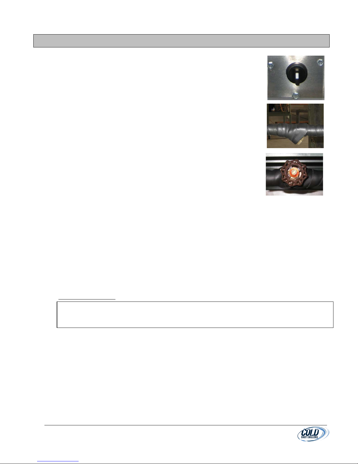
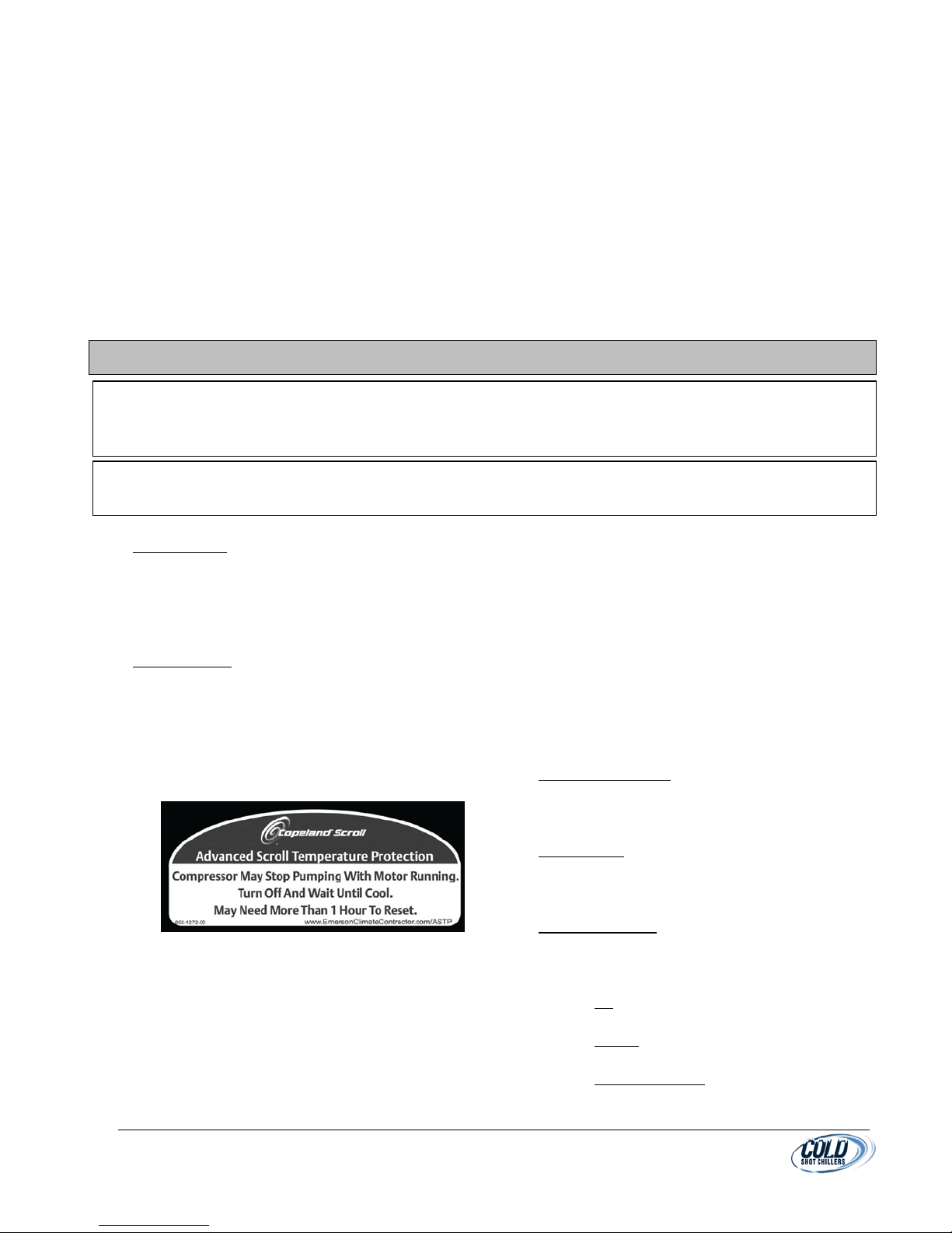
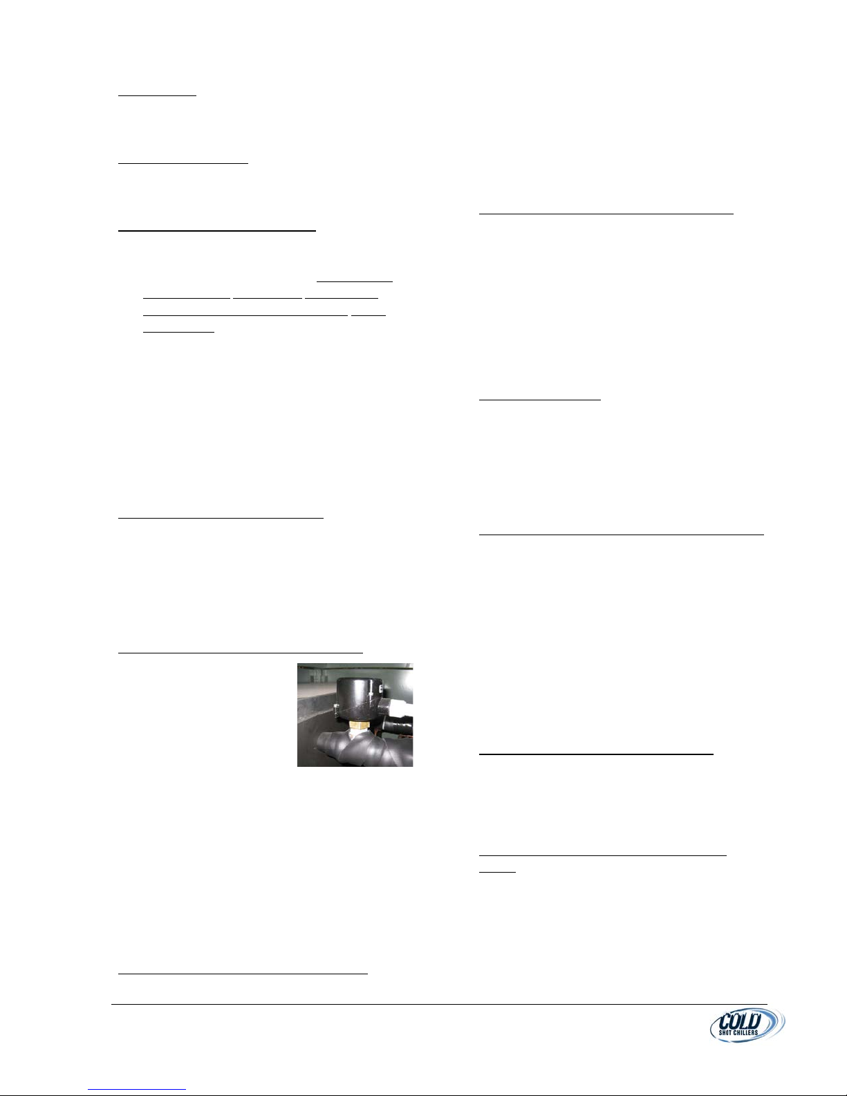
3. SERVICE VALVES
a) Verify all service valves are open. (Typical valves on these models do
not have backseats.)
4. FLUID IN SYSTEM:
a) Fill the system with the desired solution.
b) A 30% glycol mixture is recommended for all standard flow units. For
“Low Temperature” chilled fluid and units installed outdoors may
require a higher concentration to prevent freezing. See unit nameplate for specific concentration
requirements or adjust based on the ambient conditions of the chiller, fluid temperature, and/or
system design.
c) For systems with a tank, fill to within a few inches from the top edge or just to the top of the sight glass.
d) Fill system and bleed air from the highest point of piping. Vent air from pump and piping is possible by
loosening or removing the strainer blowdown plug, which will vent air as the tank is filled, as long as the
bypass valve is still open. Replace plug/cap after tank is full. Ensure that the pump and evaporator are
filled with fluid prior to starting.
e) Systems with an open tank are typically capable of bleeding excess air that is returned to the tank when
the system is operating. Piping in and out are typically below the water line.
f) For stationary systems (without an integral pump and tank), ensure that there is method for ensuring flow
through the chiller system, such as with the use of a flow switch. See electrical system or specifications
for details.
This will damage the mechanical seal in the pump and void the pump warranty.
Also, potential freeze condition may exist in the evaporator.
g) ROTATION: Check for rotation prior to start-up. Do not use pump for checking rotation unless fluid is in
the tank and the pump is full of fluid. Verify 3-Phase Power Electrical Rotation:
h) All 3-phase (3Ø) motors are wired in phase. If motors are not turning in correct direction, then reverse 2
of the incoming power wires to chiller.
i) For systems with 3Ø pumps: Pump rotation is normally clockwise as view from the back of the motor
(Refer to direction decals if available). Pumps will still pump fluid if rotating reversed, so actual
verification is necessary.
(1) Quickly depress the pump contactor to verify proper rotation.
j) For systems without 3Ø pumps: Attach refrigerant gauges to the test ports and verify that the discharge
pressure rises and the suction pressure decreases. Loud noise may be indication of wrong rotation.
Extended run time in reverse rotation will damage the compressor and lead to premature failure which
is considered abuse and not covered by warranty.
5. CRANKCASE HEATERS:
a) If compressor has crankcase heaters, allow the power to be applied to the heaters for at least 24 hours
before starting the compressor.
MNL_Standard-Basic_ACWC-24to240-E-(IN PROGRESS)_(0815).docx - 8 -
IV. STARTUP
CAUTION!: Never charge liquid into the low-pressure side of system when the system is off. Do not overcharge.
fan(s) are operating.
1. Verify installation is complete and all Pre-Startup steps are completed.
2. STARTUP CHECKLIST - Review and use. (Typically, located at end of this manual)
3. Attach refrigerant gauges to the appropriate service ports.
4. PUMP ONLY: Turn switch to Pump Only (or use local system pump) and operate for at
least 15 minutes. Shut unit down and clean strainer to remove any debris that may
have been in the system. Depending on the system cleanliness, this step may be
conducted several times to help ensure all debris is removed from the system.
5. Depending on system design, if the pump is operated for extended periods without
cooling, the fluid will heat up.
6. Once all the air is purged from the circuit and the system is free from debris, verify
that the chilled fluid has the proper flow of 3 GPM per ton of capacity.
a) Typical systems with a manual bypass valve which are factory set. The valve
must be open enough to ensure proper flow to the evaporator or the system
will shut down on low flow safety condition.
b) Process systems with automatic and variable control flows will need to ensure
that the bypass valve is throttled to accommodate all stopped process flow.
7. TEMPERATURE CONTROLLER (See Temperature Controller Section for details):
a) Set the controller to the desired Set Point value. Typically, for smaller
systems, press and hold the up or down scroll button for two seconds until
the value starts changing. Adjust the value to the desired temperature then
stop pressing any buttons. After two seconds, the new value will become operative. For larger
systems, press Set after changing temperatures. (Do not adjust the set point below the temperature
listed on the unit nameplate).
b) The controller will also display “Present Value” (upper LED readout) which is an indication of the current
temperature of the fluid in the chiller tank, or “Leaving Fluid Temperature” depending on the specific
chiller design.
8. COOLING CYCLE: Unit is now ready to turn on for cooling. Move the selector switch to “Cooling Cycle” setting
and the unit will begin cooling.
9. During the cooling cycle, condenser fans may turn on and off, due to changes in refrigerant pressure. This should
be expected during normal operation and occurs due to ambient temperature and the amount of heat being
returned in the water chiller.
10. Monitor the temperature at the process location and adjust the Set Value on the temperature controller to
achieve the desired value.
REFRIGERANT CHARGE:
11.
During charging or removal of refrigerant, be sure there is fluid flow through the evaporator and all condenser
a) Refrigerant charge may need to be adjusted from the amount listed on the equipment label to achieve
the proper operation of the chiller during final installation site as described below. Typically, on split
systems.
b) Charging refrigerant during system operation should only be performed into the suction line and then
only is small bursts to ensure liquid does not enter compressor directly.
c) Conditions to properly adjust the refrigerant charge of the system for optimum performance:
(1) Chiller to be operated against a full heat load with approximately 70°F or above water temperature.
Basically, the system must be at full capacity.
(2) Fans for condenser coil must be on. (Bypass the fan cycling switch if necessary). (Flashing may occur
in the refrigerant sight glass when fan turns on and off)
(3) Refrigerant sight glass must be clear (flooded with refrigerant) while maintaining the appropriate
subcooling and superheat parameters.
MNL_Standard-Basic_ACWC-24to240-E-(IN PROGRESS)_(0815).docx - 9 -
(4) Returning fluid temperature should not exceed 80°F on standard units or the chiller will cycle off on
IMPORTANT: Never open any switch or disconnect that de-energizes the crankcase heater unless unit is
energize the crankcase heater for 24 hours before starting the compressor.
NOTE: Schrader valve cores: Most components connected to a refrigerant fitting include a Schrader valve for
servicing. If leakage occurs during removal of a component, the valve may have been removed or damaged.
high head pressure and not run. Should this occur, allow water to cool down and restarting chiller
once water is below 80°F.
d) SUPERHEAT: Verify or set the expansion valve (TXV) superheat to approximately 10 to 12°F immediately
downstream of the TXV or approximately 12 to 14°F as measured 6 to 12 inches from the compressor
on the suction line. Adjustments should be made in small increments, such as 1/4turn or less.
e) SUBCOOLING: While cooling at low load conditions, bubbles may become visible in the refrigerant sight
glass. Ensure that the system is fully loaded, and then charge to establish approximately 10 to 14°F of
subcooling.
f) Allow approximately five (5) minutes run time for equalization of system after any changes made (add or
remove refrigerant, adjust TXV, etc).
g) Ensure all refrigerant system service ports are capped, service valves and caps tight, TXV cap is tight, etc.
V. SYSTEM COMPONENTS: (See your chiller’s specification for details.)
being serviced or is to be shut down for a prolonged period. After a prolonged shutdown on a service job,
ACCESS PANEL
1.
a. Typically, accessible where the Cold Shot
Chillers logo is located. Remove access screws
and open.
b. All hazardous area access panels must be in
place prior to operation.
COMPRESSORS
2.
a. Scroll compressors are hermetically sealed
with internal motor overload protection.
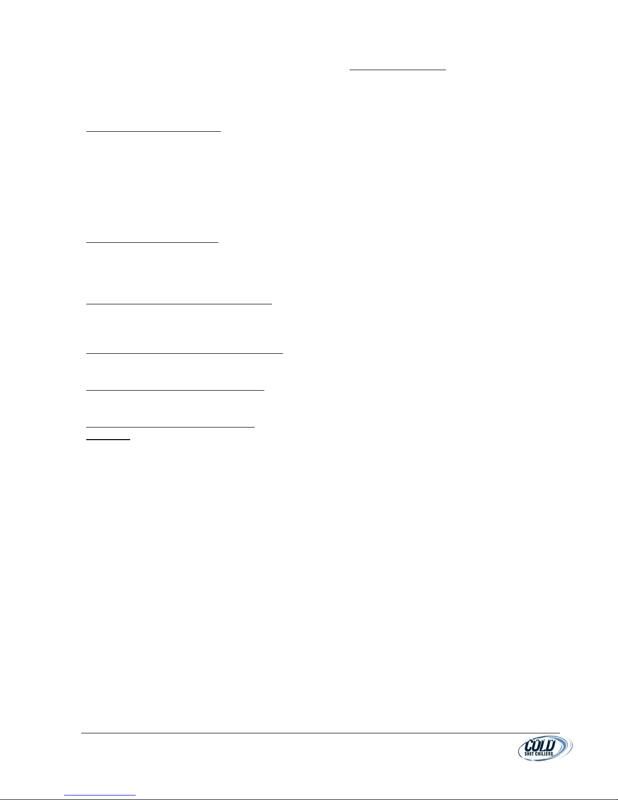
b. Most Copeland compressors are equipped
with an advanced scroll temperature
protection (ASTP). A label located above the
terminal box identifies models that contain
this technology.
c. Advanced scroll temperature protection is a
form of internal discharge temperature
protection that unloads the scroll compressor
when the internal temperature reaches
approximately 300 F. At this temperature, an
internal bi-metal disk valve opens and causes
the scroll elements to separate, which stops
compression. Suction and discharge pressures
balance while the motor continues to run. The
longer the compressor runs unloaded, the
3.
4.
5.
longer it must cool before the bi-metal disk
resets. Eventually, the motor’s internal
thermal electrical protection will shut down
the compressor.
d. To manually reset ASTP, the compressor
should be stopped and allowed to cool. If the
compressor is not stopped, the motor will run
until the motor protector trips, which occurs
up to 90 minutes later. Advanced scroll
temperature protection will reset
automatically before the motor protector
resets, which may take up to 2 hours.
CRANKCASE HEATER
a. This minimizes absorption of liquid refrigerant
by oil in casing during brief or extended
shutdown periods.
CONTROLLER
a. The digital temperature controller may vary in
design. For controller details, see the
Controller Section of this manual.
CONDENSER FANS
a. Fans operate along with the compressor
operation along with the mode controls.
b. Modes of fan cycling are:
(whenever the compressor is on).
a) On
(Typically, 3ton and under)
b) Cycling (with use of pressure actuated
“head pressure switch”. (5ton and over)
c) Speed Controlled (if using a low ambient
fan speed controller device when
operating in low ambient condition).
MNL_Standard-Basic_ACWC-24to240-E-(IN PROGRESS)_(0815).docx- 10 -
6. FILTER/DRIER
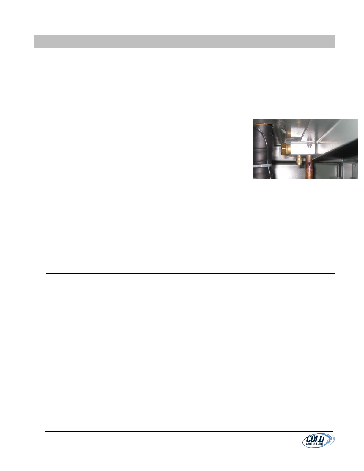
Figure 1 Flow Switch
a. For system cleanliness and moisture capture.
Every unit will have a filter drier factory
installed.
MOISTURE INDICATOR
7.
a. For system charging and moisture condition.
Every unit will have a sight glass (moisture
indicator) factory installed.
FLOW SAFETY THERMOSTAT (FST):
8.
a. Generally the cause will be low or insufficient
water flow caused by a clogged “Y” strainer or
restricted flow in the process.
Resetting this
control and not determining the cause for
tripping can cause the evaporator to freeze
and rupture.
b. Indoor chillers are normally equipped with a
Low Flow Safety temperature sensor or
thermostat that detects temperature of the
refrigerant suction. This safety will
automatically trip and requires manual
resetting before the cooling cycle will resume.
This safety can also be tripped by low ambient
conditions or during shipping.
c. Do not reset this control unless the exact
cause for its tripping is determined.
FREEZE SAFETY (FZT): (IF EQUIPPED)
9.
a. Indoor chillers are typically equipped with a
Freeze Safety temperature sensor that
detects low temperature of the fluid in the
system. This safety will automatically trip and
is reset automatically when the water
temperature returns to the higher sensor
setting difference.
LIQUID FLOW SWITCH (LFS): (IF EQUIPPED)
10.
a. Refer to the LOW FLOW
SAFETY for explanation
and cautions.
b. Outdoor units with Low
Ambient Kits are
normally equipped with
a mechanical flow
switch which monitors
the fluid entering the
evaporator. This switch is automatically reset
when the fluid flow returns to the proper flow
rate. Adjustment should not be performed
unless necessary. If adjustments are made,
ensure that the flow entering the evaporator
is greater than 3 gallons per minute per ton of
refrigeration rating of the chiller. For
example, a 2 Ton chiller will need a minimum
of 6 gpm.
REFRIGERANT LOW PRESSURE SAFETY (LPS)
11.
a) Monitors the pressure of the refrigerant
suction line and will automatically open
when the pressure drops below the set
point and will automatically reset when
pressure is above the non-adjustable
reset setting. (See specifications for
details)
REFRIGERANT HIGH PRESSURE SAFETY (HPS)
12.
a. Monitors the pressure of the refrigerant and
will automatically open when the pressure
rises above the sensor fixed set point. (See
specifications for details)
b. Reset types are manual or automatic,
depending on design and system.
c. Manual Reset - requires that a button be
pressed.
d. Automatic Reset - automatically reset when
pressure is below the reset setting.
CAPACITY CONTROLS
13.
a. System with multiple compressors permit the
use of capacity control using the temperature
controller system.
b. Hot Gas Bypass (Option) - A bypass valve in
the refrigerant system that permits cooling
output capacity of the chiller to vary based on
the load of the system.
LOW AMBIENT CONDITION CONTROLS (OPTIONS)
14.
a. Low Ambient Conditions to 0°F Kit (Option)
b. Temperature of the chiller’s ambient
condition is monitored and will change the
operation of the chiller fans to reduce the
possibility of cold temperatures affecting
condenser fan/compressor operation.
c. NOTE: Low Ambient chillers typically do not
have the Low Flow Safety or a Freeze Safety.
They are equipped with a pressure controlled
fan control system which is used to operate
the fan (or Fan #2 or #3 only on multiple fan
unit chillers).
WIND BAFFLES (DEPENDING ON DESIGN)
15.
a. Panels mounted in or on the condenser coil
section to limit/control the amount of air
entering the coils. (Option)
b. Typically used with Low Ambient kit systems
with controls down to -20°F Kit.
LOW CHILLED WATER TEMPERATURE (LOW
16.
LCWT)
a. Low Temperature refers to the temperature
of the fluid leaving the chiller is lower than
the temperature of the standard temperature
machine’s Leaving Chill Water Temperature
(LCWT). Glycol or some other freeze
protected fluid is required.
MNL_Standard-Basic_ACWC-24to240-E-(IN PROGRESS)_(0815).docx- 11 -
b. The temperature controller parameters must
be setup for the lower leaving temperatures
that the system will generate.
c. Also, some temperature thermostats may
need to be adjusted.
PUMP (DEPENDING ON DESIGN)
17.
a. Systems with integral pump are typically
setup to provide recirculating fluid for the
chiller and some flow is routed for the process
system. Refer to the unit’s actual design for
details.
b. A secondary pump may be used for process
specific applications, referred to as Process
Pump.
TANK (DEPENDING ON DESIGN)
18.
a. Systems with integral tank will typically be
304 Stainless Steel with Open Top with
Shoebox Type Lid, Fluid Level Sight glass, Fill
Port, & Drain Plug.
HEAT EXCHANGER (DEPENDING ON DESIGN)
19.
a. A heat exchanger is used to transfer heat
typically from the chiller fluid circuit to a
separate process fluid circuit.
REMOTE OPERATION/STATUS PANEL (OPTION)
20.
a. Basic On/Off control switch with Cooling
Mode status and Fault indicator light.
REMOTE OPERATION CONTROLS (OPTION)
21.
a. Various designs (contact Cold Shot Chillers for
options)
SWITCHOVER SYSTEM (CHILLER BYPASS)
22.
(OPTIONS)
a. Manual City Switchover (MCSO) (Option)
a) System valves which can be aligned to a
backup water supply system such as the
city water supply. Outlet fluid flow is
normally routed to the building’s drain
system. Valves are connected and must
be actuated simultaneously or in the
proper series to operate properly.
Converting back is normally performed in
the reverse order.
b. Automatic City Switchover (See ACSO
literature)
a) System has electrically operated valves
similar to MCSO, however it can be setup
to change automatically based on a
system safety situation.
TANK LEVEL (OPTIONS)
23.
a. Float Valve
a) Located inside the tank, the float valve is
a mechanically float-actuated valve
supplied with a makeup water source of
fluid for the tank.
b) The makeup water (such as city water
supply) is connected to the pipe
connection on the outside of the tank.
c) Water pressure, typically, must be less
than 30psi.
d) When the level falls below a certain level,
the valve will open and fill the tank.
When it reaches the top setting
adjustment, the valve closes.
e) If the valve does not maintain level:
f) Verify water pressure supply.
g) Verify the float adjustment.
h) Verify the mechanical linkages are free to
move.
i) Verify there is no dirt or debris on the
valve seat.
b. Tank Level Float Switch Solenoid Valve
a) Tank Level Switches
b) Float actuated switch(s) mounted in the
tank to monitor when tank is at different
levels depending on design such as:
a) Safety – to stop the operation of
something such as the chiller or
pump.
b) Notification – to provide a signal for
notification for manual refill or that
another action must be performed.
c) Action – to provide signal for use
with other system uses such as
automatic fill systems.
c) Low Tank Level- tank is at the low level
point that will/should begin filling the
tank. Above pump suction.
d) High Tank Level- level in tank is at or near
top of tank and tank filling will/should
stop. Tank may overflow.
c. Tank Level Float Controlled Solenoid Valve
a) A solenoid valve is an electrically
operated valve to start and stop fluid flow
from an outside source of fluid such as
city water to refill tank, typically.
MNL_Standard-Basic_ACWC-24to240-E-(IN PROGRESS)_(0815).docx- 12 -
 Loading...