

Page 1
COLD POINT CORPORATION
Cold Point Corporation, Rome, New York 13440 Phone (315)339-2331 Fax (315)339-2358 Web: www.coldpointcorp.com Cold Point Corporation, Rome, New York 13440 Phone (315)339-2331 Fax (315)339-2358 Web: www.coldpointcorp.com
CNC
SERIES
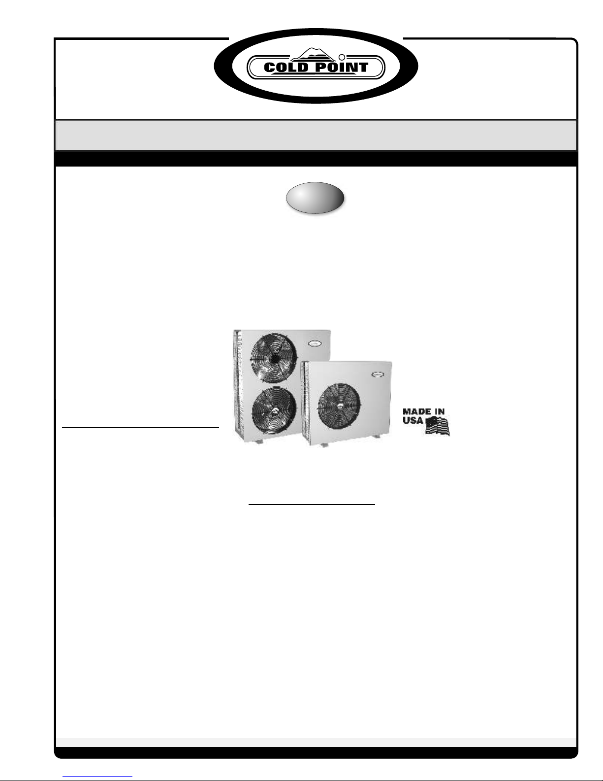
CNC Air Conditioning
Remote Condensing Unit
Installation Operation and Maintenance
CONSUMER/USER INFORMATION:
Thank You & Contact Info. __________________2
Operating Instructions ______________________2
Maintenance Instructions ____________________2
Homeowner Records________________________3
Warranty_________________________________4
INSTALLER/SERVICE CONTRACTOR
INFORMATION:
General __________________________________5
Unpacking & Inspection _____________________5
Temperature Limits _________________________5
Table of Contents
Indoor Unit & Efficiency ____________________5
Thermostat & Indoor Fan Time Delay_________5-6
Unit Location & Mounting __________________6
Electrical Wiring & Supply Voltage _____________6
Refrigerant Piping ________________________6-7
Leak Test, Evacuation & Release of Refrigerant____7
Initial Start-Up & Checks____________________7
Field Charging ___________________________7-8
Superheat Charging Chart __________________8-9
Before Calling for Service ___________________10
01-07
Page 2
CONSUMER/USER INFORMATION
SECTION:
Thank you for choosing Cold Point Corp. products! Our
goal is to make sure you remain pleased with your
decision to purchase Cold Point Corp. products. If you
are in need if assistance that is not available or
provided by your local installer/contractor feel free to
give us a call, write us, or e-mail us at:
5). IMPORTANT! Wait at least 3 minutes after turning
your air conditioner off before trying to restart it. This
gives the unit the time needed to stabilize before
restarting. Failure to do so may cause unit damage and
failure.
6). A properly installed and sized unit will not cycle more
than 10 times per hour. If you notice more frequent starts
call your service contractor.
Cold Point Corp.
7500 Cold Point Dr.
Rome, NY 13440
Phone: 315.339.2331
FAX: 315.339.2358
e-mail: [email protected]
OPERATING INSTRUCTIONS:
CNC air conditioners are designed to provide comfort
cooling at outside temperatures above 60 degrees.
Operating the air conditioner below 60 degrees may
cause unit failure and will void the Warranty. If you
have need for cooling at lower outdoor temperatures a
'low ambient cooling' option is available. Contact your
local contractor or call the factory.
TO OPERATE:
1). Set the switch on your wall thermostat to the 'cool'
position.
2). Set the desired temperature you want to maintain by
moving the temperature setting lever or dial on your
thermostat. If the room is warmer than the setting, the
unit will turn on and begin to blow cool air after a few
minutes. Note that a warm humid room or building
may take several hours of continuous operation to
cool to the thermostat set point the first time. Once
the set temperature is reached the unit will cycle on
and off.
3). Set the 'Fan' switch on the thermostat to 'auto' if
you want the fan to run only when cooling is needed
or to 'on' if you want continuous air circulation. The
'on' setting of the fan generally provides better
temperature control by eliminating stagnant air.
4). For energy conservation reasons you may want to
set your thermostat at a higher temperature when you
are away. Do not raise the temperature setting by more
than 5 degrees. Changing the temperature by more
than 5 degrees or shutting the unit 'off' can actually
cost more than leaving the setting at a constant
temperature.
MAINTENANCE:
Only simple periodic maintenance is required:
1). Change or clean the indoor unit air filter monthly or
more frequently if unusual conditions are encountered. If
you have a disposable type, throw the old one away and
install a fresh one of the same size and type. If your unit
has a washable type then vacuum and wash with soap and
water. Flush thoroughly and dry before re-installing.
2). Keep the coil in the outdoor unit clean. Periodically
flush the coil thoroughly with a garden hose. Clean away
all foreign materials such as dust, leaves, grass clippings,
papers, etc. Warning: Turn the power off first! Serious
injury or death may result if water spray is directed at live
electrical connections or power sources.
3). Yearly waxing of the exterior cabinet surfaces with a
good quality car wax will keep your unit looking new and
extend the life of the cabinet.
2
Page 3
Homeowner Records:
Date of Installation ______________________
Model No. ______________________
Serial No. ______________________
Installing Contractor _____________________________________________________________________
Address ______________________________________________________________________________
Phone No. ______________________________________ Technician's Name______________________
Service/Maintenance
Date: Work Performed By
________________ ______________________________________________________________ _____________
________________ ______________________________________________________________ _____________
________________ ______________________________________________________________ _____________
________________ ______________________________________________________________ _____________
________________ ______________________________________________________________ _____________
________________ ______________________________________________________________ _____________
________________ ______________________________________________________________ _____________
________________ ______________________________________________________________ _____________
________________ ______________________________________________________________ _____________
________________ ______________________________________________________________ _____________
NOTES:
_______________________________________________________________________________________________
_______________________________________________________________________________________________
_______________________________________________________________________________________________
_______________________________________________________________________________________________
_______________________________________________________________________________________________
_______________________________________________________________________________________________
_______________________________________________________________________________________________
_______________________________________________________________________________________________
_______________________________________________________________________________________________
_______________________________________________________________________________________________
_______________________________________________________________________________________________
_______________________________________________________________________________________________
_______________________________________________________________________________________________
_______________________________________________________________________________________________
_______________________________________________________________________________________________
_______________________________________________________________________________________________
_______________________________________________________________________________________________
_______________________________________________________________________________________________
_______________________________________________________________________________________________
3
Page 4
All Product Limited Warranty
Cold Point Corporation warrants to the purchase/owner,
that all products will be free from defects in material
and workmanship under the normal use and
maintenance.
The warranty coverage period:
From the date of original installation: Twelve, (12)
months for all components, and sixty, (60) months
on unit compressors.
Or
From the date of original sale: Fifteen, (15) months
for all components and Sixty-three, (63) months on
unit compressor from the date of original sale.
whichever comes first.
What we will cover:
PARTS: Cold Point Corp. will replace any defective part
with a new or rebuilt part at no charge. The
replacement part then assumes the remaining portion
of the warranty.
How:
PARTS: Replacement parts, except for compressors,
will be provided at no charge upon receipt of an order.
Failed compressor replacements must be authorized
and returned to Cold Point Corp. Replacement
compressors will be billed when shipped and credited
upon receipt and inspection by Cold Point Corp. See
Return Material Authorization Policy Bulletin #PB002
for details.
Normal maintenance
Damage or repairs required as a consequence of
faulty installation or application by others. Failure
to start due to voltage conditions, blown fuses, open
circuit breakers, or other damages due to the
inadequacy or interruption of electrical service.
Damage or repairs needed as a consequence of any
misapplication, abuse, improper servicing,
unauthorized alteration, or improper operation.
Damage as a result of floods, wind, fires, lightning,
accidents, corrosive atmosphere, or other conditions
beyond the control of Cold Point Corp.
Products installed outside the United States or
Canada.
Any damages to person or property of whatever kind,
direct or indirect, special or consequential, whether
resulting from use or loss of the product.
Limit of Warranties: This warranty is exclusive and in
lieu of any implied warranties of merchantability and
fitness for a particular purpose and all other
warranties express or implied. The remedies
provided for in this warranty are exclusive and shall
constitute the only liabilities on the part of Cold Point
Corp. including any statement made by any individual
which shall be of no effect.
What we do not cover:
Labor or other costs incurred for removing , installing,
shipping, or handling of defective units.
4
For Service, repair, or assistance:
1.) Contact the installer
2.) Call the nearest distributor
3.) Call, write, or e-mail:
Cold Point Corp.
7500 Cold Point Dr.
Rome, NY 13440
Phone: 315.339.2331
Fax: 315.339.2358
Web: www.coldpointcorp.com
06-06
Page 5
INSTALLER/SERVICE CONTRACTOR
INFORMATION:
Thank you for choosing Cold Point Corp. products! We
have designed and manufactured this unit to be safe
and trouble free. As the installer of this unit, you play a
major role in assuring it's intended performance and
customer satisfaction. The important information
provided here will help you install the unit correctly and
eliminate call-backs.
IMPORTANT! Alterations and replacement parts:
Altering the product or replacing parts with nonauthorized parts will void the factory Warranty and may
result in adverse operational performance and/or a
possible hazardous safety condition to service
personnel and occupants. If you are in doubt as to how
to service this unit or where to find factory
replacement parts, call Cold Point Corp. at 315.339.2331
for assistance.
GENERAL:
These instructions give information relative to Cold
Point Corp. CNC air conditioners. Local codes, if
different from these instructions, must be followed and
supplement or supersede these instructions. A
complete installation consists of: CNC condensing
unit, an evaporator unit by Cold Point Corp. or others,
interconnecting tubing and wiring, R22 refrigerant,
mounting pads and/or hardware, electrical
supply/disconnects, and a wall mounted thermostat.
UNPACKING and INSPECTION:
The CNC is shipped completely assembled and in it's
own package. All goods are inspected at the factory and
released to the freight company in good condition.
When received at the site, a visual inspection of all
packages should be made immediately. Any evidence of
rough handling or apparent damage should be noted on
the delivery receipt and the material inspected in the
presence of the carrier's representative. If damage is
found a claim should be immediately filed with the
freight company.
temperatures between 60 degrees and 115 degrees
Fahrenheit. If CNC Series air conditioners will be used
to cool at temperatures below 60 degrees, a low ambient
control must be specified or installed. Low ambient
control is available as a factory installed option or may
be field installed. Contact your Cold Point Corp. dealer or
call the factory. Operation below 60 degrees without
low ambient control will void the Warranty.
INDOOR UNIT USE and SYSTEM
EFFICIENCY:
CNC SERIES air conditioners are designed to be
compatible with most major brands of domestic
evaporator coils/air handlers. Imported ductless air
handlers maybe used but often do not include an
expansion device. A properly sized thermostatic
expansion valve is recommend and is available from
Cold Point.
The U.S. Department of Energy, (D.O.E.), mandates
that all systems achieve a minimum efficiency of 13.0
Seasonal Energy Efficiency Rating, (SEER). All CN
SERIES units meet or exceed 13.0 SEER when used
with Cold Point Corp. indoor units, see Table 1. Indoor
units not supplied by Cold Point Corp. must be selected to
meet the minimum 13.0 SEER, efficiency rating.
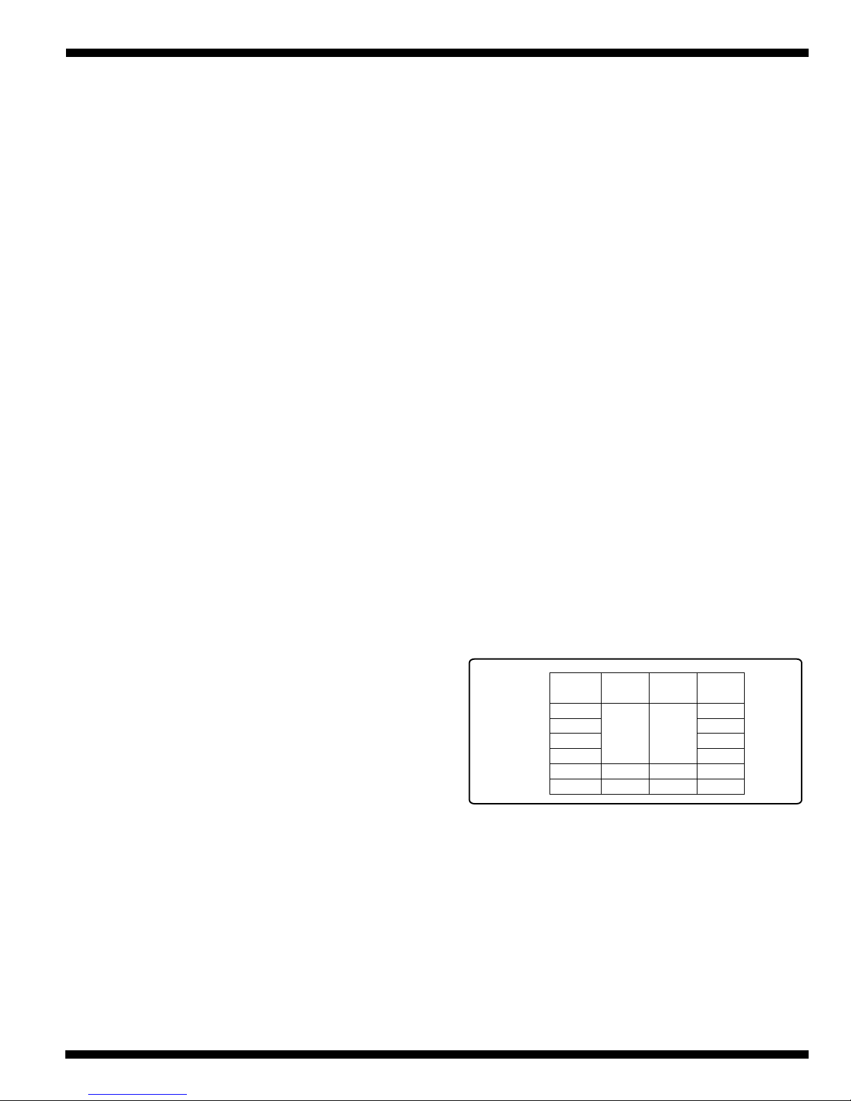
Use the following indoor coils supplied by Cold Point
for an approved/matched system:
Table 1
Model
No.
CNC- 18
CNC- 24
CNC- 30
CNC- 36
CNC- 48
CNC- 60
Cold Point
Part #
20159
20160
20161
Evap Coil
Ref. #
TRUF37TR5
TRUF49TR-6
TRUF61TR-8
Nominal
CFM
600
800
1,000
1,200
1,600
2,000
THERMOSTAT and INDOOR FAN TIME
DELAY:
All indoor units should include a fan time delay. This
may be accomplished by using a Cold Point digital wall
thermostat or installation of a 60 second fan time delay
designed to work with your specific furnace/air handler.
COOLING OPERATION TEMPERATURE
LIMITS:
CN SERIES units are designed in accordance with ARI
standards and will operate in cooling at outside
Cold Point digital thermostats include a fan delay as do
most brands of electronic thermostats.
5
Page 6
Thermostats are available from Cold Point Corp. Use of
thermostats not supplied by Cold Point Corp. are the
responsibility of the installer.
Proper temperature control and unit operation
depends on proper thermostat selection and location.
Refer to the thermostat manufacturer's installation
instructions for specific recommendations. Good
practice is to avoid outside walls, locations where the
sun may shine directly on the thermostat, and locations
where the air from supply registers or unit outlets blow
on the thermostat. Also avoid locations where the
thermostat could be jarred by a closing door.
UNIT LOCATION and MOUNTING:
Choose a location that places the CN unit as close to
the indoor unit as possible. The maximum separation
is 100 feet. Maximum vertical lift (compressor above
evaporator) is 35 feet.
Avoid high traffic areas and areas where water, snow,
or ice may fall from a roof onto the unit. In climates
where snow is a consideration, locate the unit away
from areas prone to drifting. For heat pump
installations be sure to raise the unit above expected
snow levels.
For wall mounting, assure that mounting frames and
hardware are corrosion resistant and of adequate size
and strength to support the unit. For ground or roof
mounting provide a level pad or platform.
Insure free flow of air into and out of the unit. Stay
clear of obstructions such as walls and shrubs.
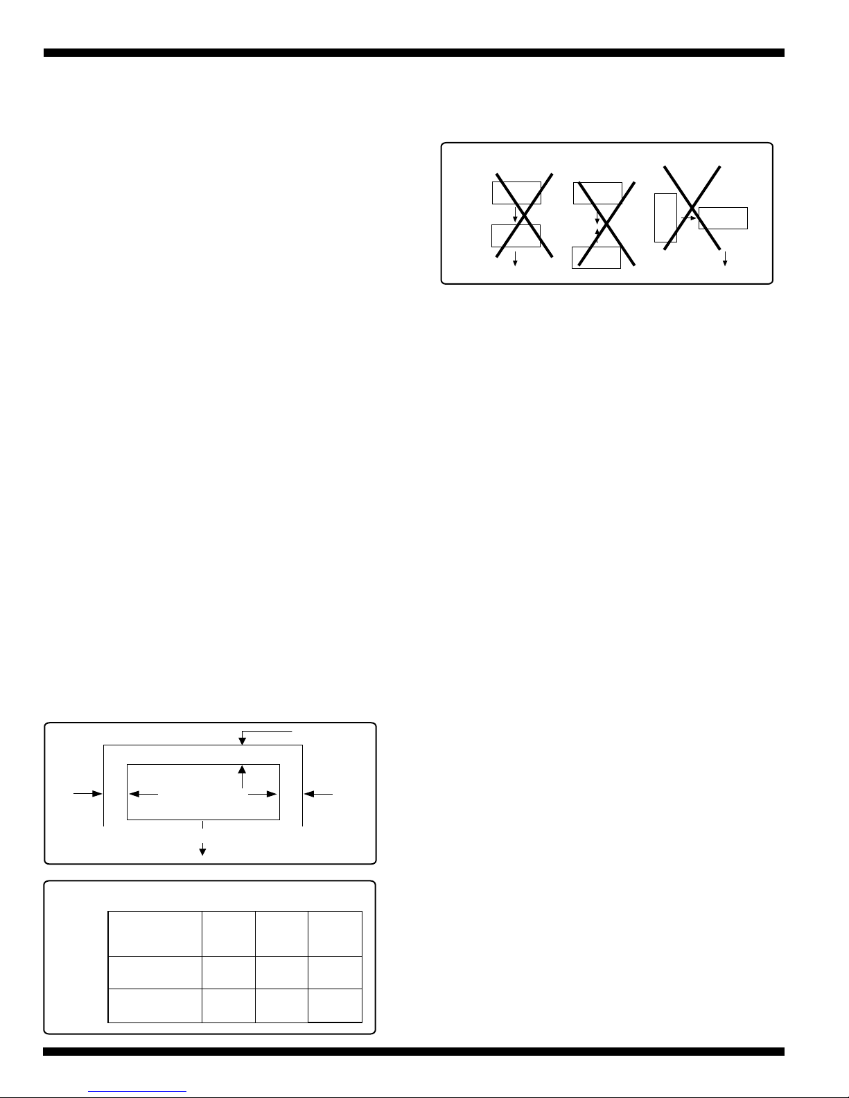
Minimum clearances must be adhered to as illustrated
in Fig. 1 and in accordance with Table 2.
FIG. 1
AIR INLET
A
A
SERVICE
SIDE
B
block air flow or in a way that hot air from one unit will
blow into a nearby unit. See Fig. 2.
FIG. 2
ELECTRICAL WIRING and SUPPLY
VOLTAGE:
All electrical wiring must be run according to NEC and
local codes. Nameplate data indicates the operating
voltage, phase, ampacity, maximum over current
protection, and minimum voltage. Use copper
conductors only.
The contractor is to provide branch circuit over current
protection for the unit as required by code. Run power
supply wiring through a weatherproof disconnect box
and conduit to the unit connection. Disconnects are
required to be within sight and easy reach of the unit,
(usually within 3 feet).
For low voltage wiring use NEC class 2 wire. Check the
unit wiring diagram for the number of conductors
required. Route neatly and protect from sharp edges and
damage.
CN SERIES units are rated for use on 230V power
supply circuits. Unit performance and life depend on a
supply voltage that is maintained between 207V and
253V. Inadequate wiring and/or improper electrical
supply will likely result in failure of the compressor and
other electrical components and voids the Warranty.
C
B CA
8”
11”
18”
18”
Table 2
AIR OUTLET
MINIMUM CLEARANCE
Model
No.
CNC-09, 12,
18, 24
CNC-30, 36,
48, 60
6
Do not locate two or more units in a way that will
48”
48”
REFRIGERANT PIPING:
The length of refrigerant lines and the number of bends
determine the pressure drop which affects capacity and
efficiency of the system and oil return to the compressor.
The outdoor unit connections are sweat type. Tube size
should always be the same diameter as the connections
provided at the service valves. Up sizing of lines can
result in inadequate oil return to the compressor and
excessive refrigerant charge and will void the Warranty.
See Table 3.
Page 7
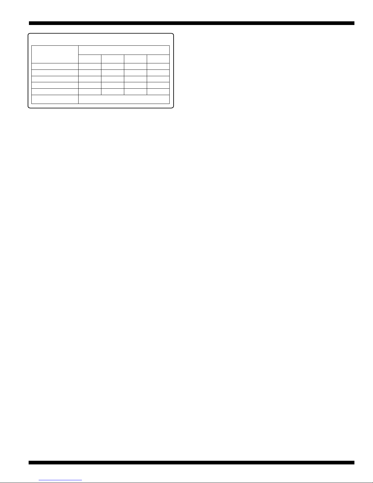
Table 3
Refrig. Line
Data.
Max. Line Length
Max. Elevation
Max. Number Bends
Liq. O.D.
Suction O.D.
‘P’ Trap (invert)
09,12 18,24 30,36
100 100
10
1/4”
1/2”
Choose a location that places the CN unit as close to
the indoor unit as possible. The maximum separation is
100 feet of piping. Use only clean refrigeration grade
tubing. Avoid piping on wet or rainy days. Always keep
the tube ends capped until you are ready to make the
final connections. Remove burrs from cut ends of
tubing. Use tube benders to avoid kinking.
Insulate the suction line with Armaflex or equivalent
with a wall thickness of at least 3/8". Support the
tubing adequately to avoid sags that can trap oil. Isolate
the tubing so as not to transmit noise to the building
structure. Avoid sharp edges that could cut the tubes.
Maximum vertical lift (compressor above evaporator) is
35 feet. Trap risers with a 'P' trap every 10 feet.
Model
100
3535
10
3/8”
5/8”
Every 10’ of Rise
35
10
3/8”
3/4”
48,60
100
35
10
1/2”
7/8”
2). Connect a charging manifold to the service ports
provided at the service valves.
3). Pressurize the lines and evaporator with nitrogen and
leak check all connections with soap bubbles. Repair as
necessary any faulty joints. If brazing is required be sure
to RELEASE THE NITROGEN FIRST. Re-test as
needed.
4). Connect a vacuum pump to the manifold center
connection, start the pump and open the manifold
valves.
5). Evacuate to 500 microns or less for a minimum of
30 minutes. Close the manifold valves and shut off the
pump. Note the vacuum reading and wait 15 minutes.
Take a new vacuum reading. A reading of 800 microns
or higher indicates the presence of moisture or a leak.
6). Repair as necessary and repeat steps 3, 4 & 5.
7). Confirm that manifold valves are closed and
disconnect the vacuum pump.
8). Remove the caps from the services valves. Using an
allen wrench open the valves to the fully 'back-seat'
position. Replace service valve caps and tighten.
INITIAL START-UP & CHECKS:
Operation of the unit is automatic and will provide
cooling depending on the setting of the thermostat.
Units are supplied with a filter drier for installation in
the liquid line. Install in a convenient location. Protect
from excessive heat while brazing connections.
LEAK TEST, EVACUATION & RELEASE of
REFRIGERANT:
The CN unit is supplied with R-22 charge sufficient for
most matching evaporator units. Charge must be
added for interconnecting tubing.
The unit's service valves are shipped in the closed
position and should not be opened until final
connections and evacuation are completed.
WARNING: It is illegal to discharge refrigerant into
the atmosphere. Use proper reclaiming methods and
equipment when working on the refrigerant containing
parts of the unit. Service should be performed by a
QUALIFIED service agency and certified technicians.
The recommended procedure for leak test, evacuation,
and release of refrigerant is outlined below:
1). Complete the final piping connections to the indoor
and outdoor units using high temperature brazing alloy.
IMPORTANT! All panels must be installed, main power
turned on and the thermostat properly connected
before operating the unit.
1). System check - set thermostat system switch to
"Off" position and fan switch to "Auto" position. Turn
the power supply breaker on.
2). Set the fan switch to "On" , blower should operate.
3). Return the fan switch to "Auto". Blower should shut
off. Set the system switch to "Cool" and lower
thermostat set point to coldest setting. The compressor,
condenser fan, and evaporator blower should all come
on. Cool air will be supplied after a couple of minutes
of run time.
4). Proceed to the ‘FIELD CHARGING’ section of
these instructions.
7
Page 8
FIELD CHARGING:
Unit performance, efficiency, and life depends, to a
large extent, on a proper system charge. Time spent on
getting the charge right at start-up will pay off in the
long run.
Operating conditions such as voltage, air flow,
evaporator coil size, and indoor and outdoor
temperature and humidity all have an effect on the
system pressures and superheat conditions.
CNC series units are factory charged for the outdoor
and indoor unit and factory supplied filter drier.
Charge must be added for the interconnecting tubing.
Cold Point supplied evaporator coils are supplied with
non-bleed type thermostatic expansion valves. Use the
sub-cooling method or verify/adjust charge (see page
7).
subtract the suction pressure equivalent temperature
(saturated suction).
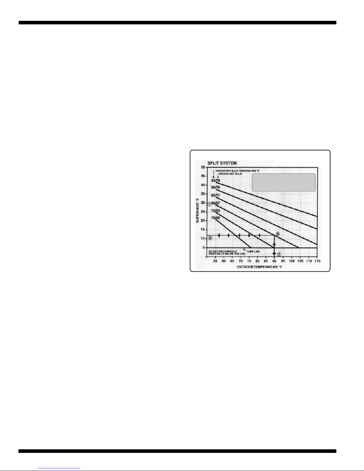
5). Proceed to the Superheat chart (Fig. 3). Add or
remove R-22 to achieve the superheat reading
indicated by the chart.
IMPORTANT: When connecting the manifold to the
charging bottle be sure to purge the hose of air with a
small amount of R-22.
Wait at least 5 minutes between charge adjustments to
allow the unit to stabilize.
6). When charge adjustment is complete remove the
manifold hoses from the service valves and replace and
tighten service port caps.
Fig. 3
Use the following ‘superheat’ and ‘sub-cooling’
methods to verify proper charge after adjustments are
made.
SUPERHEAT METHOD FOR FIXED
ORIFACE/ CAPILLARY TUBE INDOOR
UNITS:
For fixed metering devices such as bullet orifices,
pistons, and cap tubes the superheat method will always
be the method used. Measuring superheated vapor
values at the suction service valve is one of the most
important indicators of proper system performance. If
the superheat is too high, the evaporator coil will under
perform. If too low, there is a risk of damaging the
compressor with liquid refrigerant. A fixed metering
device is unable to control super heat; therefore, proper
superheat values can vary greatly with conditions that
affect it, such as outdoor and indoor air conditions. Use
the steps outlined in steps 1 thru 6.
* If relative humidity is above 70%
or below 20%, use indoor Wet
Bulb Temperature.
Chart based on 400 cfm/ton indoor airflow and 50% relative
humidity; use only on systems that cool with an fixed oriface or
capillary tube.
PROCEED as FOLLOWS:
1). Run the unit for at least 10 minutes to allow the
system to stabilize. Then take readings of the indoor
and outdoor air temperatures and suction pressure.
Write them down.
2). On the gauge face, read the equivalent temperature
on the R-22 scale next to the suction pressure reading.
3). Using a thermocouple or probe type thermometer
read the suction line temperature as it enters the service
valve. Make certain that the thermocouple/probe is
tight to the copper line.
4). From the thermocouple thermometer reading
8
Page 9
and reclaiming methods are used. Technician
certification is required by law.
SUB-COOLING METHOD FOR EXPANSION
VALVE INDOOR UNITS:
An air conditioning system utilizing a thermostatic
expansion valve (TXV or TEV) for its metering device
will automatically maintain proper evaporator superheat
regardless of varying operating conditions. Therefore,
when charging a TXV system, the charge is adjusted to
assure that there is pure liquid refrigerant, void of any
flash gas, entering the expansion device. Verifying a
liquid ‘seal’ at the expansion valve can be accomplished
by measuring the sub-cooling, (sub-cooling is the
sensible heat removed from the liquid refrigerant as it
travels through the last passes of the condenser). As
with superheat, the proper level of sub-cooling is
important. If the sub-cool level is too low or
nonexistent, flash gas will form, causing restricted flow
through the TXV reducing system capacity. Higher
than normal sub-cooling is an indication that liquid
refrigerant is "backing up" in the condenser, reducing
its effective condensing area. If too high, due to an
overcharge, it can lead to high condensing pressure
problems.
FINAL INSPECTION:
Do a final visual inspection of the entire installation and
complete any final details and clean up.
Review Unit Operation with the homeowner/user.
PROCEED as FOLLOWS:
1. Operate unit a minimum of 10 minutes prior to
checking refrigerant charge.
2. Measure liquid service valve pressure by attaching an
accurate gage to the service port. Determine saturation
temperature from T/P chart.
3. Measure liquid line temperature by attaching an
accurate thermistor type or electronic thermometer to
liquid line near service valve.
4.Calculate sub-cooling (Saturation temp.-measured
temp.)
5.Sub-Cooling should be 15 deg. Add refrigerant if
sub-cooling is lower than 15deg. Recover refrigerant if
sub-cooling is higher than 15 deg..
6. Whenever charge is removed or added, the system
must be operated for a minimum 20 minutes to
stabilize before additional measurements can be made.
RECHARGE:
When it is necessary to completely recharge the system
refer to the unit nameplate for the starting charge.
Verify the final charge using the ‘superheat’ or ‘subcooling’ method. Be sure proper refrigerant handling
9
Page 10
Installer/Contractor Records:
BEFORE CALLING the FACTORY for ASSISTANCE
A call to the factory is sometimes necessary for technical support or service/troubleshooting. We are happy to help! Before
calling please gather and record the following information so that we are best able to help you.
Cold Point Corp.
7500 Cold Point Dr.
Rome, NY 13440
Phone: 315.339.2331
FAX: 315.339.2358
e-mail: [email protected]
Outdoor Unit Model No.: ____________________________________________
Outdoor Unit Serial No.: ____________________________________________
Indoor Unit Model No.: ____________________________________________
Indoor Unit Serial No.: ____________________________________________
Condition of outdoor unit coil and indoor air filter _________________________
Name of Job or Installation: _________________________
Your Name: _________________________
Your Company's Name: _________________________
Your Company's Address: __________________________
Your Company's Phone & FAX No.: __________________________
Outdoor Temperature: ____________________________________________
Indoor Temperature: ____________________________________________
Suction Pressure: ____________________________________________
Suction Superheat: ____________________________________________
Liquid line Pressure: ____________________________________________
Voltage @ Contactor: ____________________________________________
Amp Reading (clamp on): ____________________________________________
Your Diagnosis or Question:
_______________________________________________________________________________________________
_______________________________________________________________________________________________
_______________________________________________________________________________________________
____________________________________________________________________________________
Factory rep recommendations:
Date:_______________________
Factory rep's name:_____________________________
Recommendations:________________________________________________________________________________
_______________________________________________________________________________________________
_______________________________________________________________________________________________
_______________________________________________________________________________________________
10
Cold Point Corporation 7500 Cold Point Dr. , New York 13440 Phone 315.339.2331 Fax 315.339.2358 Web: www.COLDPOINTCORP.com Rome
CNC IOM- 01-07
 Loading...