

Cold Jet RDS 500 Cub Parts & Maintenance Manual
MODEL
Parts &
Maintenance
Manual
1-800
-3DRY-ICE
CJI# 2W0238A
1

Serial No.: ___________________
Voltage: 100-120 Volts AC
Model No.: RDS 500 Cub
Control No.: 2A0145
Diagram: 6G0116
Voltage: 200-230 Volts AC
Model No.: RDS 500 Cub
Control No.: 2A0145
Diagram: 6G0117
This manual illustrates the safety, operation, and maintenance features of the RDS 500 Cub.
The design contain ed in th is m anual was or iginated by, and is the exc lusive pr operty of Cold Jet, I nc. It is not to be used
in any way detrimental to the interests of Cold Jet, Inc.
No part of this design or manua l ma y be reproduced, transm itted, stored in a retr ieval s ystem , or translated into an y other
language or computer language, in whole or i n part, in any form or by any means, whether it be el ectronic, mechanical ,
magnetic, optical, manual or otherwise, without the express written consent of Cold Jet, Inc.
1-800
-3DRY-ICE
Copyright 2000 by
Cold Jet, Inc.
All Rights Reserved
Printed in U.S.A
2

Special Notes
All information contained within this manual, or information derived from exposure to the technology
or equipment supplied by Cold Jet, Inc. remains "CONFIDENTIAL" between Cold Jet, Inc. and the
purchaser or authorized user. Any unauthorized transfer of information to any person or company not
in the direct employ of Cold Jet Incorporated, or not in the direct employ of, or for, the purchaser, or
the authorized user, is strictly prohibited by agreement.
Warranty Compliance
All procedures, specifications, main tenance and configurations of any and all Cold Jet systems and
their supporting equipment, as well as the installation thereof, must have the express written
knowledge and approval of Cold Jet, Inc. or warranties can become invalidated. Furthermore the use
of Cold Jet systems in any unsafe, unspecified, or in any unauthorized manner can immediately
invalidate any and all warranties.
For Your Information
If you have questions about our product lines, applications for our equipment, the environmental
impact of our equipment or would like more technical information please visit our web site at
www.coldjet.com.
1-800
-3DRY-ICE
3

1-800
-3DRY-ICE
4

Table of Contents
Special Notes ....................................................................................................................................3
Warranty Compliance ........................................................................................................................3
For Your Information ..........................................................................................................................3
1. Troubleshooting ____________________________________________________________ 7
2. Maintenance _______________________________________________________________ 9
Preventive Maintenance .........................................................................................................9
On a Daily Basis ..........................................................................................................9
On a Weekly Basis .......................................................................................................10
On a Monthly Basis ......................................................................................................11
Every Three Months ..................................................................................................... 12
500 Hour Scheduled Maintenance ..........................................................................................13
Tuning Fork Replacement ......................................................................................................14
Appendix A: Performance ______________________________________________________ 17
Appendix B: Specifications _____________________________________________________ 19
Appendix C: Electrical Schematics _______________________________________________ 21
120 Volt ..................................................................................................................................21
230 Volt ..................................................................................................................................22
Appendix D: Assemblies _______________________________________________________ 23
1-800
-3DRY-ICE
5

1-800
-3DRY-ICE
6

Section 5
Section 5 Troubleshooting
Section 5 Section 5
Problem Check This
Machine will not start.
Troubleshooting
Troubleshooting Troubleshooting
1. Is the unit plugged in ?
2. Is the power Switch in the ON position?
3. Reset E-stop.
4. Is the FEEDER RESET ready? If not, press to
reset.
5. Is the 24V Power fuse blown (the indicator will be
red)?
1. Is the air supply CONNECTED and the air supply
on?
2. Is the air supply gauge showing pressure?
3. Is the OPTIONAL pressure regulator open?
Machine will NOT blast.
Machine blasts AIR but NOT
4. Is applicator cable CONNECTED to Cub and the
applicator?
5. Is the BLAST pressure gauge showing pressure
when the trigger is pulled?
6. The NOZZLE may be clogged, blast with air only
to unclog the nozzle.
1. Set feeder speed.
2. Check Vibrator.
pellets.
3. Unclog NOZZLE.
If these recommendations DO NOT solve your problem, contact our Technical Service hotline:
1-800-777-9101.
1-800
-3DRY-ICE
7

1-800
-3DRY-ICE
8

Section 6
Section 6 Maintenance
Section 6 Section 6
Maintenance
Maintenance Maintenance
Preventive Maintenance
On a Daily Basis
1. Drain water out of the coalescing filter before using
the machine. (turn pet-cock fully open to drain the
water)
2. While in operation check all gauges.
3. Make sure the feeder reset light is on.
Figure 1
Figure 2
4. Make sure the caster wheels will lock.
5. Check the air and blast hoses for damage, like cuts
or scuff marks.
6. Make sure the applicator’s blast cable is NOT
wound around the blast hose .
Figure 6
Figure 3
Figure 4
1-800
-3DRY-ICE
Figure 5
9
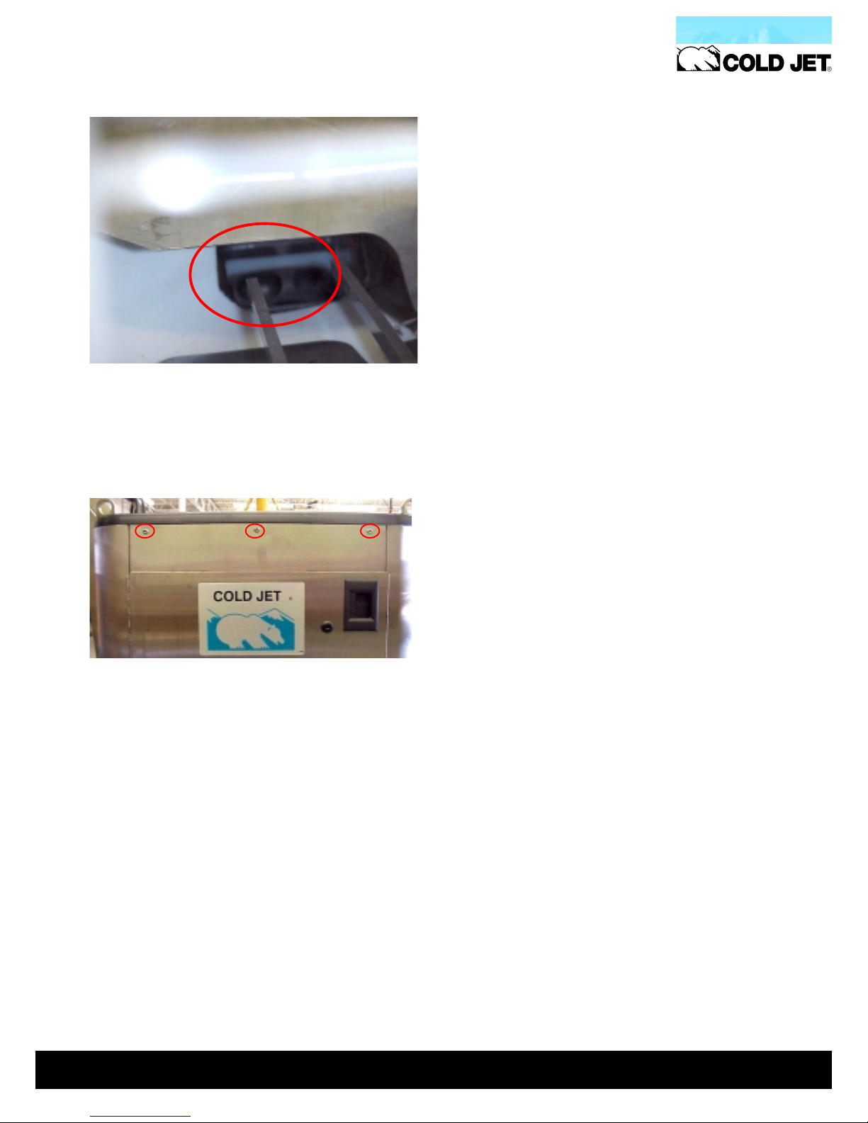
On a Weekly Basis
1. Look through the hopper to check the rotor
for nicks or gouges.
(Use a flashlight).
2. Make sure the Cub’s screws are tight.
1-800
-3DRY-ICE
10
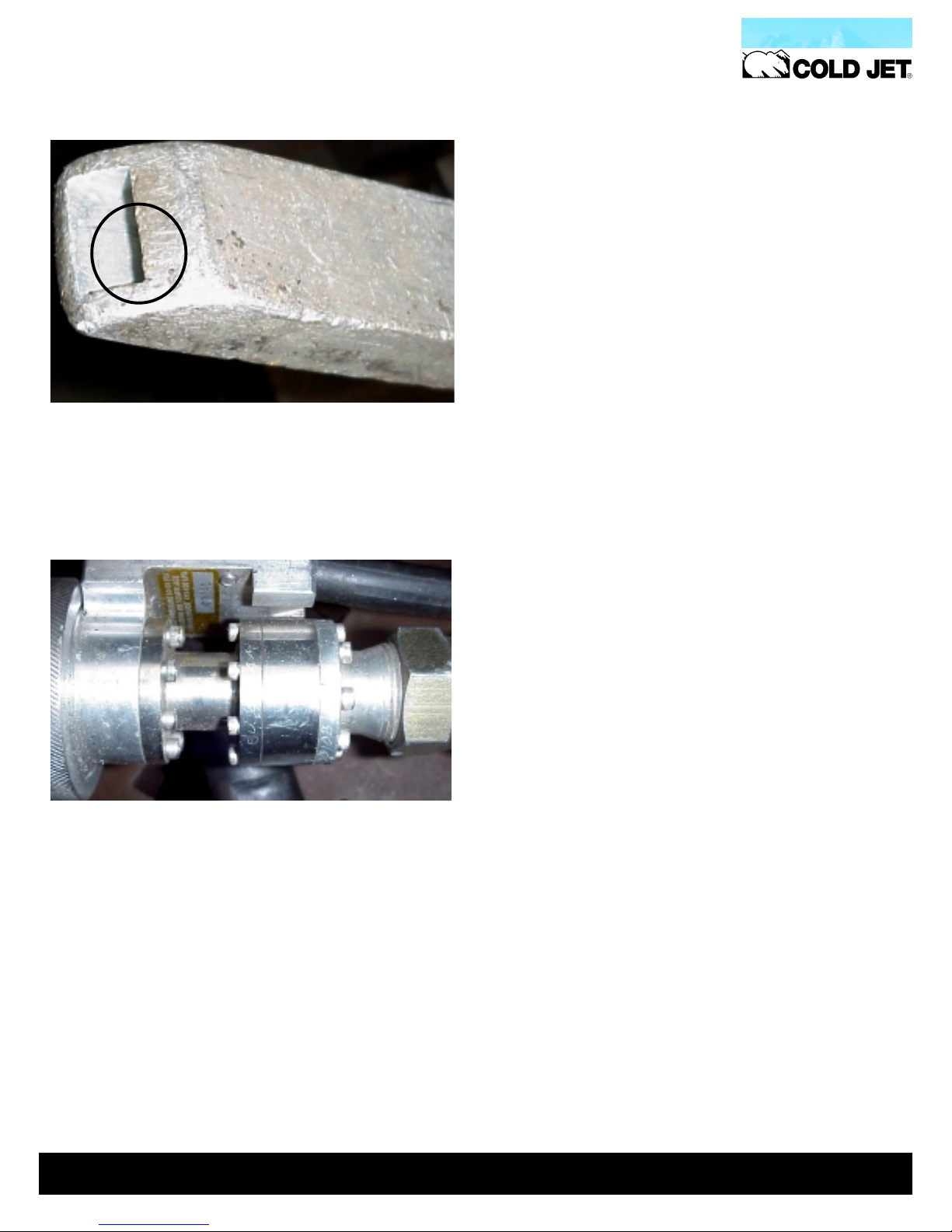
On a Monthly Basis
1. Make sure the nozzle airflow exit end is not
deformed or burred.
2. Tighten all screws on Applicator Rotary
Union.
1-800
-3DRY-ICE
11

Every Three Months
Every Three Months
Every Three MonthsEvery Three Months
1. Make sure the vibrator motor bolts are at a
torque setting of 40 ft-lbs.
1-800
-3DRY-ICE
12

500 Hour Scheduled Maintenance
If you are not an authorized Cold Jet service technician,
please call to schedule this service.
1. Check pads and rotor
2. Check upper and lower tension springs
3. Check voltage and amperage on DC drive
4. Check specs on AC controller
5. Check brushes in the vibrator motor
6. Check condition of power cord
7. Check all light bulbs
8. Check all gauges
9. Check static ground reel
10.Inspect hoses for damage
11.Replace consumable parts
Check the tuning fork
Check the filter element
12.Check the accessories
13.Safety test the unit
14.Check all valves
1-800
-3DRY-ICE
13
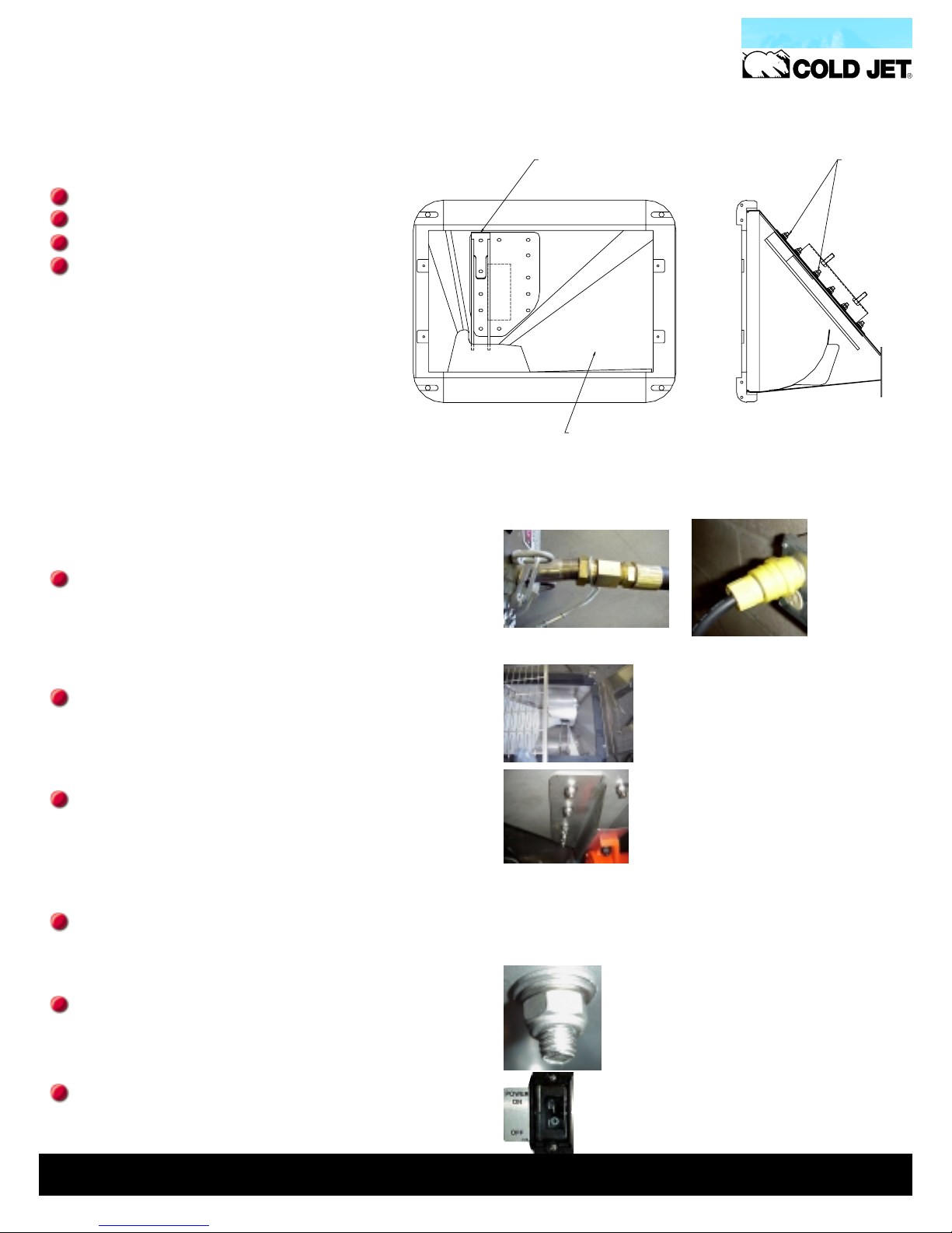
Tuning Fork Replacement
The tuning fork is easy to replace, and should take only 15-20 minutes to complete
INSTALL NEW VIBRATING
Tools required:
Large Phillips screwdriver
3/32” Hex key
13 mm socket wrench
Anti-seize compound or graphite lubricant
PELLET AGITATOR 3J0504
REMOVE HOPPER SCREEN
REPLACE AFTER NEW AGITATOR
IS INSTALLED
USE THREAD LUBRICANT
TIGHTEN TO 15 FT/LBS
Remove t h e old tuning fork
Remove compressed air supply and electric
power from the machine.
Remove the safety screen from the top of the
hopper (do not let anything fall into the
feeder).
Open the side door of the machine and remove
the old tuning fork by unscrewing the two 8 mm
ny-lock nuts that hold it in .
Install the new tuning fork
Use a small quantity of anti-seize compound or
graphite lubricant on the studs to prevent galling
during assembly.
Torque the nuts to approximately 11.5 ft-lb. Be
sure to install washers in the order they were removed.
Attach the power cable and press the power
button (DO NOT ATTACH THE COMPRESSED
AIR HOSE)!
1-800
-3DRY-ICE
14
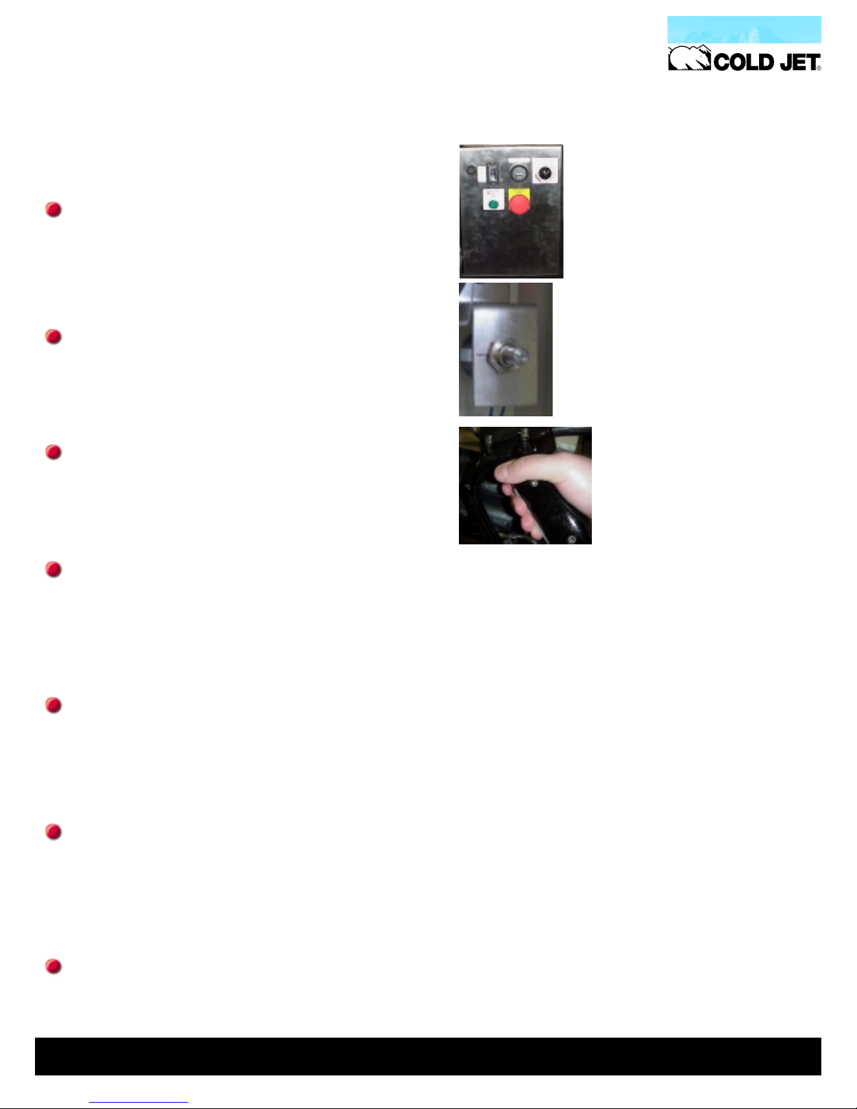
Fine tuning the tuning fork
Open the Controls enclosure on the front of the
Cub
Loosen the potentiometer shaft from the silicone
seal.
Pull the blast gun trigger; this will cause the vibrator motor to jump to HIGH for around 1 to 2
seconds, followed by a drop to LOW.
Once the machine is vibrating on LOW, adjust
the potentiometer shaft clockwise or counter
clockwise until the tips of the tuning fork vibrate
between ¼” and ½”.
It may be necessary to bend one of the tuning
fork tines to avoid chatter on the hopper shield.
This will be obvious because of excessive noise.
Once the vibrator motor is tuned, shut off the
blast trigger, and re-seal the potentiometer shaft
with silicone.
Disconnect the power to the machine and reinstall the safety screen.
1-800
-3DRY-ICE
15

1-800
-3DRY-ICE
16

7.0
6.5
6.0
5.5
5.0
4.5
Appendix A
Appendix A Performance
Appendix A Appendix A
PELLET FEED RATES
STANDARD AND OPTIONAL ROTORS
Performance
Performance Performance
Standard-Feed
4.0
3.5
3.0
2.5
Pellet Feed (pounds-per-minute)
2.0
1.5
1.0
0.5
0.0
0 102030405060708090100
1-800
-3DRY-ICE
Feed Rate Setting(%)
17
 Loading...