

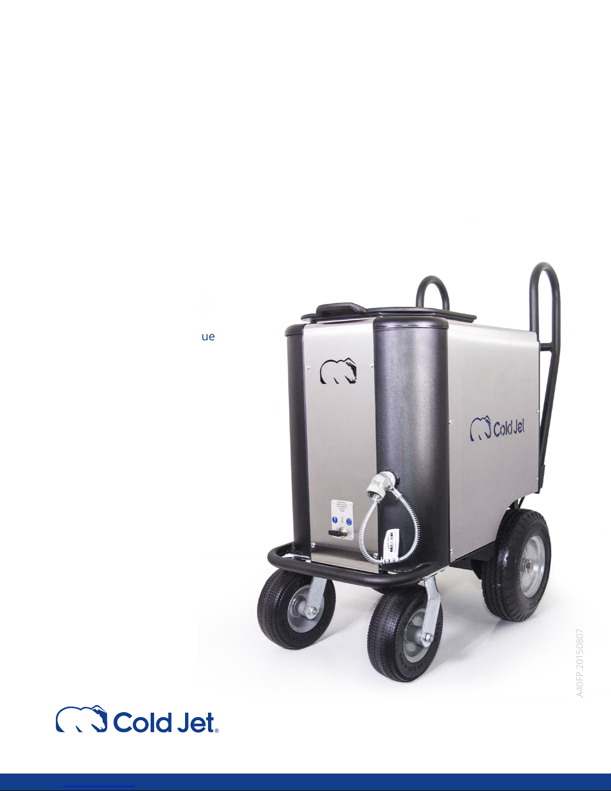
Aero 40FP
OPERATOR MANUAL
1 Safety Guidelines
General Safety Requirements
Electrostatic Discharge
CO
5 Component Guide
Specications
Components
12 Unit Operation
Start Up
Blast Cleaning Technique
Shut Down
16 Maintenance
Symbol Glossary
Maintenance
Troubleshooting
Contacting Cold Jet
Warranty
Safety
2
24 Appendix A
Blast Air Quality
26 Appendix B
Residual Risks
27 Appendix C
Schematics
42 Index
Original Instructions
OM.A40FP.20150807

EC Declaration of Conformity
We as the manufacturer:
Cold Jet, LLC
455 Wards Corner Road
Loveland, OH 45140 US
+1 513 831 3211 / +1 513 831 1209
declares that the following product:
Product Designation: Aero 40FP Model no.: 2A0290 Voltage: 120/230 VOLTS AC
complies with all relevant requirements of the directives listed below:
Directive 2006/42/EC [Machinery Directive]
Directive 2004/108/EC [EMC Directive]
References to the harmonized standards used:
Person in the European Community authorized to compile the technical documentation:
Cold Jet Europe bvba, Mr. Wim Eeckelaers, Zone 1 Researc hpark 330 B-1731 Zellik, Belgium
Place and Date of Issue: Loveland, OH
Michael E. Rivir
V.P.-Engineering,Cold Jet, LLC.
Copyright© 2015 Cold Jet, LLC
All rights reserved
Printed in the U.S.A
Due to continued product development this information may change without notice. The information
and intellectual property contained herein is condential between Cold Jet and the client and remains
the exclusive property of Cold Jet. If you nd any problems in the documentation, please report them to
us in writing. Cold Jet does not warrant that this document is error-free.
No part of this publication may be reproduced, stored in a retrieval system, or transmitted in any
form or by any means, electronic, mechanical, photocopying, recording or otherwise without the prior
written permission of Cold Jet.
This manual reects the product conguration as was current at the time of initial production. An
item’s display in this manual does not guarantee the item’s availability at any time in the future. Images
shown are for representative purposes only. Products may vary from the images displayed. Cold Jet is
not liable for typographical errors or changes to specications presented.
EN ISO 12100:2010 EN ISO 4414:2010 EN ISO 13857:2008
EN 953:1997+A1:2009 EN ISO 13732-3:2008 EN 60204-1:2006/AC:2010
EN 1088:1995+A2:2008 EN ISO 13849-1:2008/AC:2009
1
OM.A40FP.20150807
OM.A40FP.20150807
Dry ice cleaning is similar to sand blasting, plastic bead blasting or soda blasting where a medium
is accelerated in a pressurized air stream to impact a surface to be cleaned or prepared.
However, instead of using hard abrasive media to grind on a surface (and damage it), dry ice
cleaning uses soft dry ice accelerated at supersonic speeds to impact the surface and lift the
undesirable item off the underlying substrate.
DRY ICE CLEANING:
•isanon-abrasive,nonammableandnon- conductivecleaningmethod
• is environmentally-responsible and cont ains no secondary contaminants such as
solvents or grit media
• is clean and approved for use in the food industry
• allows most items to be cleaned in place without time- consuming disassembly
•canbeusedwithoutdamagingactiveelectricalormechanicalpartsorcreatingrehazards
• can be used to remove production residues, release agents, contaminants, paints, oils
andbiolms
• can be as gentle as dusting smoke damage from books or as aggres sive as removing weld
slag from tooling
• can be used for many general cleaning applications
Cold Jet dry ice cleaning uses compressed air to accelerate frozen carbon dioxide (CO
2
) “dry ice”
pellets to a high velocity. Dry ice pellets can be made on-site or supplied. Pellets are made from
food grade carbon dioxide that has been specically approved by the FDA, the EPA and the USDA.
Carbon dioxide is a non-poisonous, liquefied gas, which is both inexpensive and easily stored at
work sites.
WHAT IS DRY ICE
CLEANING?
SAFETY GUIDELINES
Aero 40FP

2 3
OM.A40FP.20150807
OM.A40FP.20150807
The Aero 40FP is safe and easy to operate; however, certain precautions must be followed during its use. To
understand all the necessary precautions, you must read the entire Aero 40FP manual before operating the
unit.
The Aero 40FP should only be operated by authorized and trained personnel.
IN THIS SECTION
General Safety Requirements. . . . . . . . . . . . . . . . . . . . . . . . . . 2
Electrostatic Discharge. . . . . . . . . . . . . . . . . . . . . . . . . . . . . . 3
CO2 Safety . . . . . . . . . . . . . . . . . . . . . . . . . . . . . . . . . . . . . . 4
GENERAL SAFETY REQUIREMENTS
• Always follow the guidelines of the governing codes of your local/national body as a minimum
standard for ensuring safety.
• Always wear thermal gloves, eye and ear protection (safety glasses and ear plugs).
• Never expose bare skin to CO
2
ice.
• Never point the nozzle at self or anyone else and always exercise extreme caution when people are in
the blast area.
• Never use a wire tie to hold the applicator trigger in the on position. This will cause damage that will
void the warranty.
• Never use the blasting unit or hoses for anything other than the intended use.
• Never operate in a conned space without an approved ventilation system.
• Never operate the unit with guards removed.
• Never mask the machine’s ventilation holes.
• Never operate a damaged blasting unit.
• Never exceed recommended hose or blasting unit pressure levels.
• Do not kink the blast hose before, during or after operation.
• Never disconnect the air supply hose without rst shutting o the source air and removing the line
pressure.
• Only Cold Jet trained service technicians are certied to work on electrical components.
SAFETY GUIDELINES
• Do not operate equipment with electrical parts exposed, jumpered or rendered inoperable.
• Only use dry ice pellets as the cleaning media.
• Always engage applicator safety switch before laying it down or passing it to someone.
• Always turn the main power o and remove the applicator control cable before removing the blast
hose.
• Always ensure that hoses are securely attached.
• Keep hoses and power cord out of forklift trac areas.
• Check hoses and cables for nicks and gouge.
ELECTROSTATIC DISCHARGE
• Static discharge may ignite ammables.
• Electrostatic discharge can be hazardous to the operator and the equipment.
• The static charge of CO2 varies with the amount of dry ice and humidity present.
Ground the Material Being Cleaned
Always ground the material being cleaned to assure safe operation while blasting.
1. Know your environment.
• Electrostatic buildup changes as humidity levels change and will vary by location. Electrostatic
discharge is higher at low humidity levels and occurs most often during winter.
2. Attach static bond cable.
• To minimize electrostatic buildup between the part being cleaned and the applicator, attach the static
bond cable between the target surface and the blast hose connection or to an electrically conductive
supporting structure. Use a conductivity tester for conrmation.
3. Plug into a grounded power outlet.
• This step is critical for electrostatic dissipation. If the ground is not connected, a charge may build up
on the unit or the applicator.
SAFETY GUIDELINES

4 5
OM.A40FP.20150807
OM.A40FP.20150807
CO2 SAFETY
• The Aero 40FP uses solid state carbon dioxide (CO2). CO2 is nontoxic, noncorrosive and non-conductive.
It is approved by the FDA and USDA.
• Solid CO
2
is extremely cold (-109 °F/-78 °C). Always protect skin from direct contact with CO2 pellets.
Direct contact with skin or eyes quickly causes tissue damage.
• Vapor CO
2
can displace the oxygen from any breathing environment rapidly.
• Only operate the 40FP with a proper ventilation system that maintains the concentration levels of the
governing codes of your local/national body.
• Always review and observe all safety guidelines when using materials that displace oxygen.
• All operators and supervisors should familiarize themselves with the literature on the physiological
characteristics of CO
2
before using the 40FP. The information can be obtained from the governing
codes of your local/national body.
• Always use a CO
2
monitoring device when using the 40FP in a conned space.
SAFETY GUIDELINES
COMPONENT GUIDE
Aero 40FP
6 7
OM.A40FP.20150807
OM.A40FP.20150807
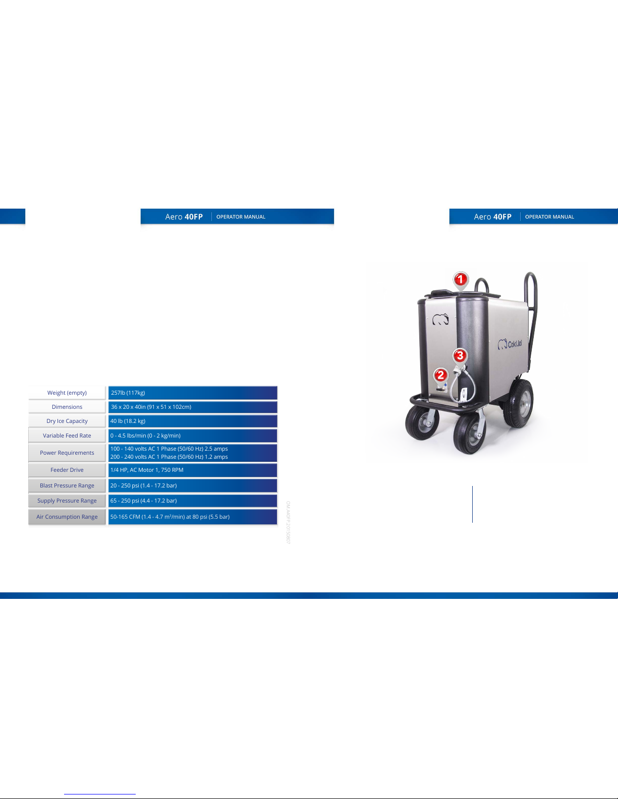
COMPONENT GUIDE
AERO 40FP (FRONT)
The 40FP guarantees the best pellet integrity, maximum cleaning aggression, and the most reliable blast
stream on the market. In addition to the standard Aero features, the 40FP uses multiple agitation devices
to eliminate clogging—allowing you to blast through the 40lb hopper without stopping.
IN THIS SECTION
Specications. . . . . . . . . . . . . . . 6
Front. . . . . . . . . . . . . . . . . . . . . 7
Back. . . . . . . . . . . . . . . . . . . . 8
Control Panel. . . . . . . . . . 9
Applicators . . . . . . . . . 10
SPECIFICATIONS
1
Fill lid
3
Air supply connection
2
Bleed valve
Weight (empty) 257lb (117kg)
Dimensions 36 x 20 x 40in (91 x 51 x 102cm)
Dry Ice Capacity 40 lb (18.2 kg)
Variable Feed Rate 0 - 4.5 lbs/min (0 - 2 kg/min)
Power Requirements
100 - 140 volts AC 1 Phase (50/60 Hz) 2.5 amps
200 - 240 volts AC 1 Phase (50/60 Hz) 1.2 amps
Feeder Drive 1/4 HP, AC Motor 1, 750 RPM
Blast Pressure Range 20 - 250 psi (1.4 - 17.2 bar)
Supply Pressure Range 65 - 250 psi (4.4 - 17.2 bar)
Air Consumption Range 50-165 CFM (1.4 - 4.7 m
3
/min) at 80 psi (5.5 bar)
8 9
OM.A40FP.20150807
OM.A40FP.20150807
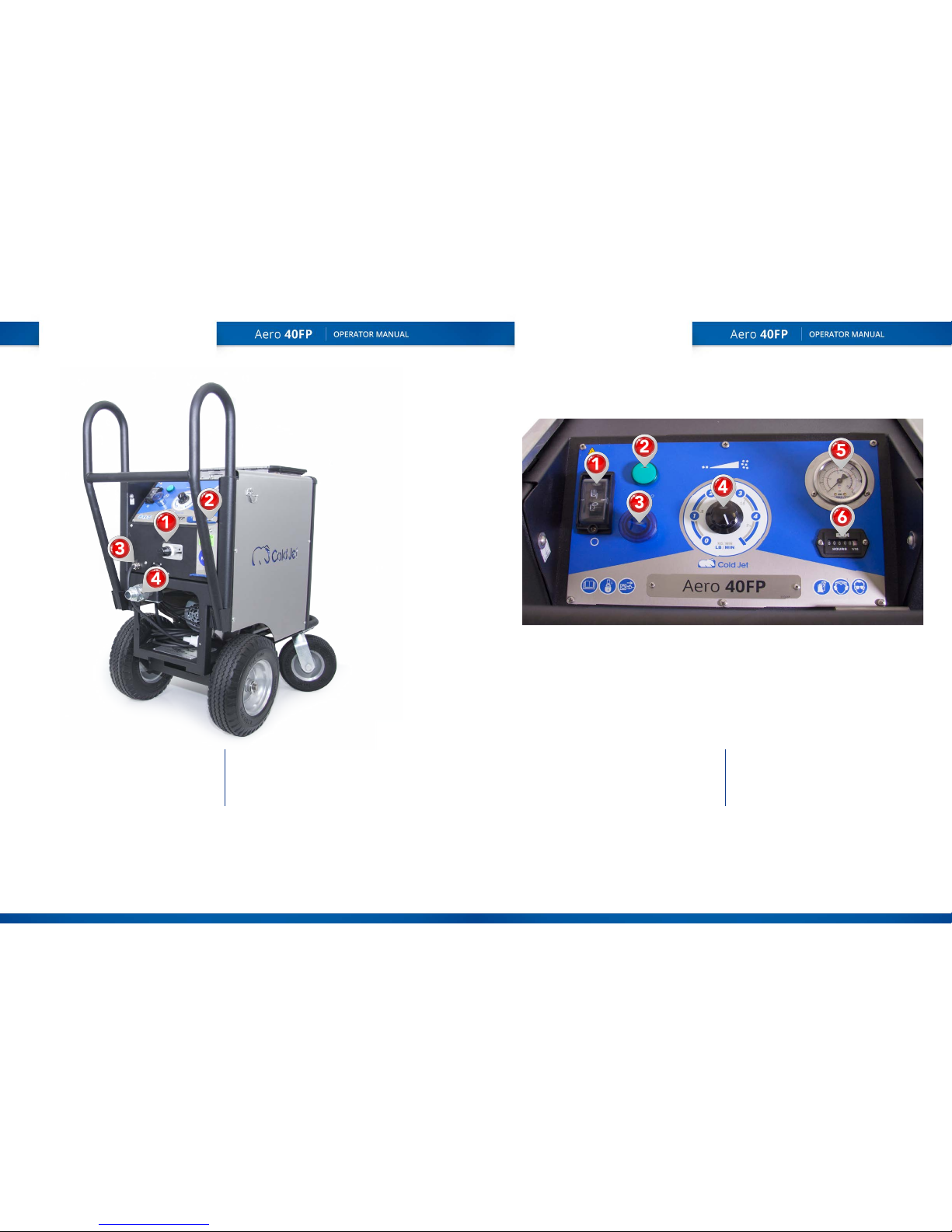
AERO 40FP (BACK)
CONTROL PANEL
1
Power switch
4
Feed rate control
2
Blast / power indicator
5
Incoming / blast air pressure
3
Disable blast, blue light = disabled
6
Hour meter
1
Blast pressure control
3
AC power cord
2
Nozzle hanger
4
Blast hose connection
10 11
OM.A40FP.20150807
OM.A40FP.20150807
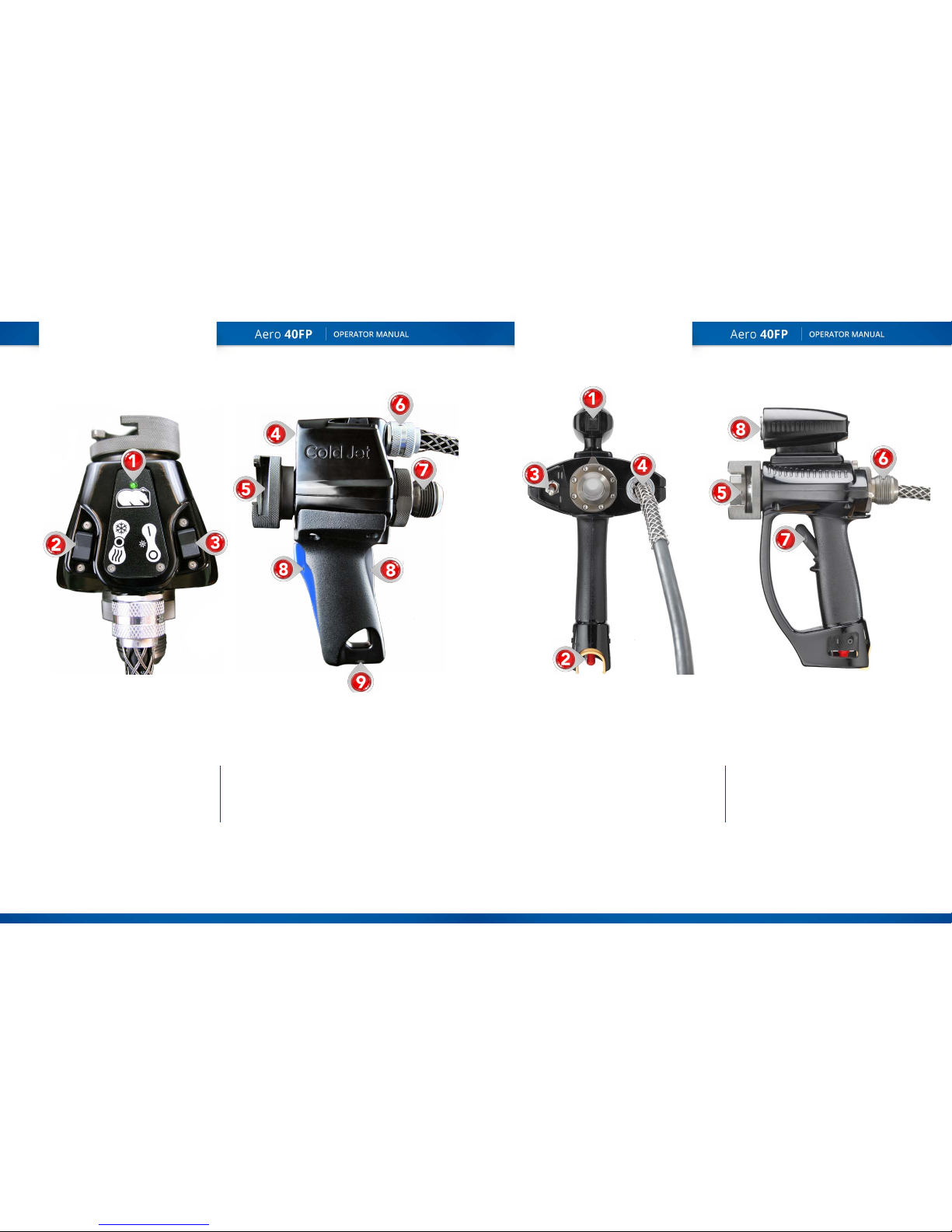
PERFORMANCE
APPLICATOR
HEAVY DUTY
APPLICATOR
1
LED light switch (optional)
5
Nozzle retention collar
2
Applicator safety switch
6
Blast hose connector
3
Air / ice control
7
Trigger
4
Electric cable connection
8
LED light (optional)
1
Machine power indicator
6
Electric cable connection
2
Air only - o - air & ice
7
Blast hose connector
3
Light switch
8
Front / rear concurrent hand trigger
4
Blast lights
9
Threaded mount & hook hanger
5
Nozzle retention collar
 Loading...