

Page 1
1
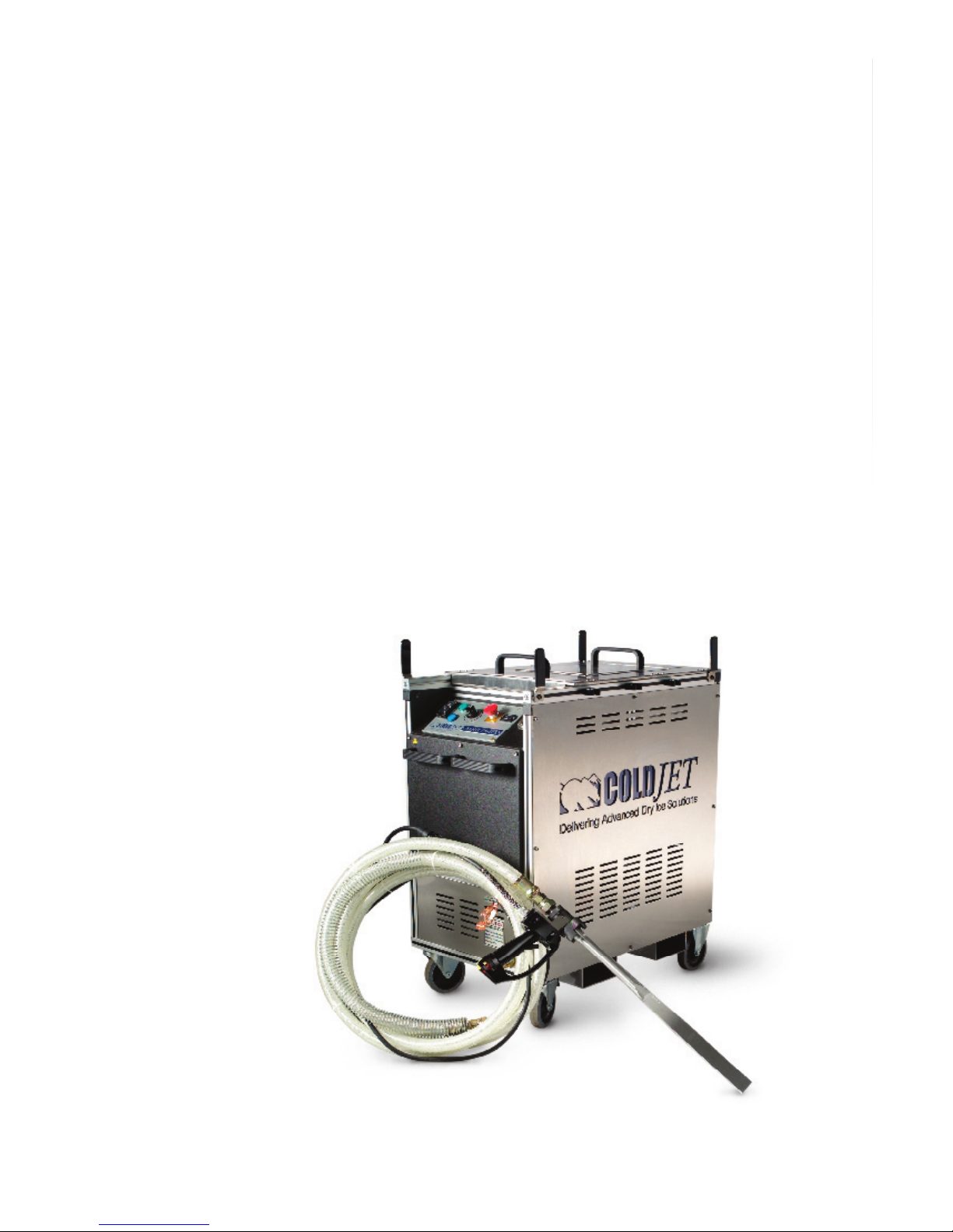
Operator Manual
AeRO 75 Series
Page 2

2
This manual illustrates the safety, operation, and maintenance features of the Cold
Jet AeRO 75 Series.
The build and revision level is located on the machine’s data plate.
All Machine diagrams are located on the inside of the electrical cover plate.
The design contained in this manual was originated by and is the exclusive property
of Cold Jet, LLC. It is not to be used in any way detrimental to the interests of
Cold Jet, LLC.
No part of this design or manual may be reproduced, transmitted, stored in a
retrieval system, or translated into any other language or computer language, in
whole or in part, in any form or by any means, whether electronic, mechanical,
magnetic, optical, manual or other, without the express written consent of Cold Jet,
LLC.
Special Notes
All information contained within this manual, or information derived from
exposure to the technology or equipment supplied by Cold Jet, LLC remains
“CONFIDENTIAL” between Cold Jet, LLC and the purchaser or authorized user.
Any unauthorized transfer of information to any person or company not in the
direct employ of Cold Jet, LLC, or not in the direct employ of the purchaser or the
authorized user, is strictly prohibited.
Voltage:
100-130 Volts AC
Model No.:
AeRO 75
Control No./
Diagram:
2A0148-G1
Voltage:
200-240 Volts AC
Model No.:
AeRO 75
Control No./
Diagram:
2A0148-G1
Voltage:
100-130 Volts AC
Model No.:
AeRO 75-DX
Control No./
Diagram:
2A0148-G2
Voltage:
200-240 Volts AC
Model No.:
AeRO 75-DX
Control No./
Diagram:
2A0148-G2
Copyright 2007 by
Cold Jet
All Rights Reserved
Printed in U.S.A.
P/N: 2W0245-C
Page 3

3
Table of Contents
Safety
General Safety Precautions ...................................................................6
Electrostatic Discharge ..........................................................................7
Carbon Dioxide .....................................................................................8
Blast Hose Safety Precautions ..............................................................9
Finger Guard Precautions ......................................................................10
Component Guide
Introducing the Cold Jet AeRO 75 & AeRO 75-DX ................................15
Front View .............................................................................................16
Back View .............................................................................................18
Control Panel ........................................................................................20
Hopper ..................................................................................................21
Regulator Configuration .........................................................................25
Coalescing/Particulate Air Filter ............................................................27
Blast Applicator .....................................................................................28
Operation
Starting Up ............................................................................................32
Blasting .................................................................................................34
Shutting Down ......................................................................................35
Maintenance
Troubleshooting .....................................................................................38
Daily/Weekly Maintenance ....................................................................39
Monthly/Biannual Maintenance .............................................................41
Appendix
Specifications ........................................................................................44
Tips .......................................................................................................45
Blast Air Quality .....................................................................................46
Cold Jet Services ..................................................................................48
Machine Symbols ..................................................................................49
Warranty ...............................................................................................51
Page 4

4
Page 5

5
Safety
Page 6

6
Safety
• NEVER OPERATE the unit without first reading the Operator Manual.
• NEVER EXPOSE bare skin to CO2 ice.
• ALWAYS WEAR safety glasses, gloves, 32+NRR ear plugs & ear
muffs.
• EVERYONE in the blast area must comply with all safety requirements.
• NEVER POINT the nozzle at anyone and ALWAYS exercise extreme
caution when people are in the blast area.
• NEVER use a wire tie to hold the applicator trigger in the ON position.
Doing so can damage it and void its warranty.
• NEVER USE the blasting unit for anything except the intended usage.
• ONLY USE dry ice pellets as the blasting media.
• NEVER OPERATE in a confined space without an approved ventilation
system and a carbon dioxide monitoring device is recommended.
• NEVER mask the ventilation holes.
• NEVER ALLOW UNTRAINED PERSONNEL to operate the blasting
unit.
• NEVER OPERATE a damaged blasting unit.
• ALWAYS turn the main power OFF and remove the applicator control
cable BEFORE removing the blast hose.
• NEVER exceed recommended hose or blasting unit pressure levels.
• ALWAYS ground the material being cleaned.
• ALWAYS ENSURE that hoses are securely attached.
• KEEP hoses and power cord out of forklift traffic areas.
• CHECK hoses and cables for nicks and gouges.
• DO NOT kink the blast hose before or during operation.
• NEVER DISCONNECT the air supply hose without first shutting off the
source air.
• ONLY COLD JET TRAINED service technicians are allowed to work on
the unit’s electrical components.
• DO NOT operate equipment with electrical parts exposed, jumpered or
rendered inoperable.
• ALWAYS FOLLOW THE GUIDELINES of the governing codes of your
local/national body as a minimum standard for ensuring safety.
• Please refer to Carbon Dioxide (CO2) MSDS sheet for all safety
precautions. (MSDS sheet available upon request.)
General Safety
Precautions
Page 7

7
Electrostatic Discharge
Safety Precautions
Safety
Electrostatic discharge can be hazardous to the operator and the
equipment. The static charge of CO2 varies with the amount of ice and
humidity present. Follow these instructions to assure safe operation while
blasting.
A) The power outlet must have a good ground
This is critical for electrostatic dissipation. If the ground is not
connected a charge will build up on the unit or the applicator. As a
secondary backup the unit's electrically conductive wheels will help
bleed off any additional static charge.
B) The blasting unit’s static ground cable must be attached to the
target surface
If a target is on a non-grounded surface it will build up an electrostatic
charge, which could injure the operator or damage the equipment.
Wrap or clip the static ground cable to the target to dissipate the
charge. Metal framing, that holds the target in place, can be used but
the target and frame must be electrically connected. Use a conductivity
tester for confirmation.
C) Know your environment
Electrostatic buildup changes as humidity levels change and will vary
by location. Electrostatic discharge is higher at low humidity levels and
occurs most often during cold weather.
Page 8
8
Carbon Dioxide (CO2) is a naturally occurring gas and a normal by-product
of breathing.
However caution MUST be exercised!
• This unit utilizes Carbon Dioxide (Dry Ice) as a blast media.
• Dry Ice is very cold -110°F (-79°C) and may freeze skin instantly.
• CO2 is a heavy gas, which means it will settle to the ground.
• Always ventilate when blasting.
• When blasting in a confined space, use of a Carbon Dioxide monitoring
device is recommended.
• CO2 is nontoxic, non-corrosive, non-conductive and is approved by
the FDA and USDA. While exposure to CO2 gas is not harmful in low
concentrations, CAUTION must be exercised when using any material
that can DISPLACE OXYGEN.
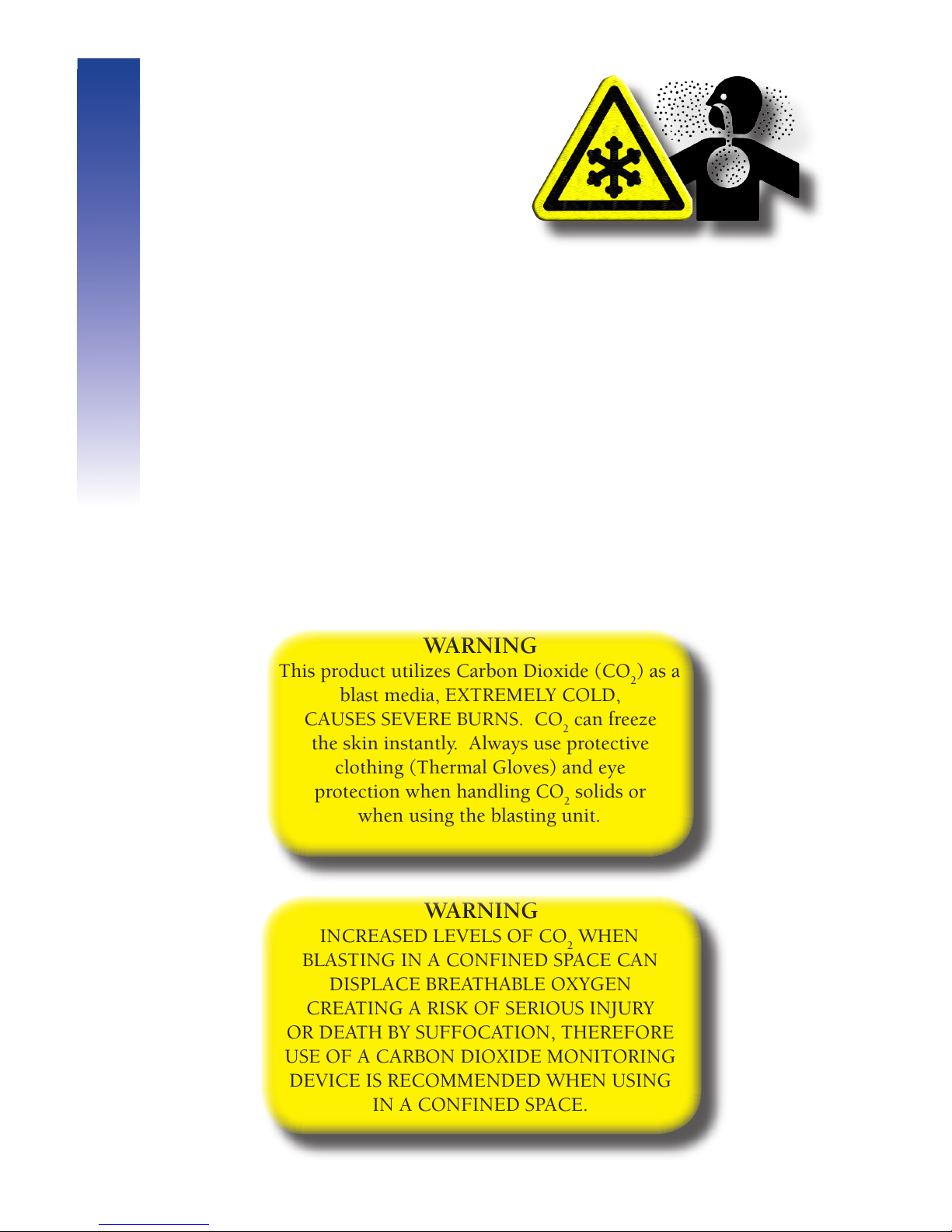
WARNING
This product utilizes Carbon Dioxide (CO2) as a
blast media, EXTREMELY COLD,
CAUSES SEVERE BURNS. CO2 can freeze
the skin instantly. Always use protective
clothing (Thermal Gloves) and eye
protection when handling CO2 solids or
when using the blasting unit.
Carbon Dioxide
Safety Precautions
Safety
WARNING
INCREASED LEVELS OF CO2 WHEN
BLASTING IN A CONFINED SPACE CAN
DISPLACE BREATHABLE OXYGEN
CREATING A RISK OF SERIOUS INJURY
OR DEATH BY SUFFOCATION, THEREFORE
USE OF A CARBON DIOXIDE MONITORING
DEVICE IS RECOMMENDED WHEN USING
IN A CONFINED SPACE.
Page 9

9
• ALWAYS tighten hose fittings with a wrench.
• NEVER USE hoses above the recommended working pressure. (see
table)
Blast Hose Safety Precautions
Part Number Description Working
Pressure
Machine
2N0177 3/4" Urebrade Hose 140 psi
(9.65 bar)
AeRO 75
AeRO 75-DX
(Low Pressure)
2N0178 1" Urebrade Hose 140 psi
(9.65 bar)
AeRO 75
2N0179 1-1/4" Urebrade
Hose
140 psi
(9.65 bar)
AeRO 75
AeRO 75-DX
(Low Pressure)
2N0180 1" Kevlar Hose 300 psi
(20 bar)
AeRO 75-DX
(High Pressure)
2N0181 1-1/4" Kevlar Hose 300 psi
(20 bar)
AeRO 75-DX
(High Pressure)
Safety
• NEVER DISCONNECT the supply air hose without first shutting off the
source air.
• BLEED the compressed air before disconnecting the hoses.
• NEVER OPERATE the equipment if the hose whip check is not
installed.
Page 10
10
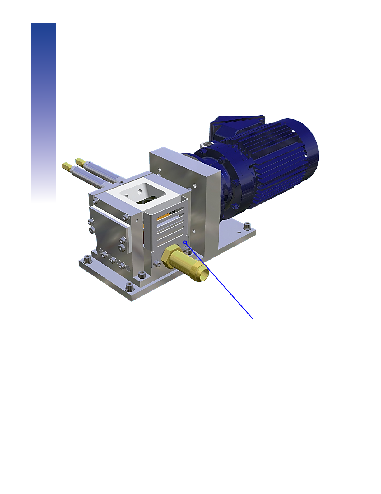
The finger guard on the Cold Jet AeRO 75 series protects from a potential
personal injury site located inside the machine. The guard, over the air
exhaust port, must remain installed at all times to serve its function.
Finger Guard
Finger Guard Precautions
Safety
Page 11

11
IMPORTANT
ALWAYS MAKE SURE THE HOPPER IS
EMPTY AND BLAST WITH AIR ONLY,
FOR 1 MIN. WHEN SHUTTING DOWN
LONGER THAN 15 MIN.
FAILURE TO DO SO MAY RESULT IN
FEEDER AND/OR NOZZLE FREEZE-UP.
• For optimal performance it is recommended that the air supply dew
point be -40oF (-40oC) or lower.
• For optimal performance make sure the air is clean and free from oil
and grit.
• If needed, use an after-cooler and an air dryer with air filtration,
to obtain desired air quality and dew point (air drying and filtration
equipment may be purchased from Cold Jet).
• If you intend to provide your own air drying and filtration equipment,
consult Cold Jet Customer Support for assistance in selecting the
correct models.
• The length of blast time at higher dew points depends on relative
humidity, temperature and excessive condensation in the hopper and
on the pellets.
• At EVERY blasting start-up ALWAYS purge the Cold Jet AeRO 75 &
75-DX with compressed air before adding pellets to the hopper.
• ALWAYS shut the fill lid to avoid foreign objects falling in.
• ALWAYS avoid bad ice.
Before You Begin
Safety
Page 12

12
Page 13

13
Component
Guide
Page 14

14
Page 15

15
Component Guide
• The Cold Jet AeRO 75 & 75-DX are portable units providing easy
access for difficult to reach cleaning applications.
• The Cold Jet AeRO 75 & 75-DX use dry ice pellets from either an on-
site pelletizer or shipped in from a distribution center.
• The blast machine requires a source of compressed air and standard
electrical power for operation.
• The blast machine contains an innovative, patented feeder and control
system to maintain consistent pellet flow.
• During operation the feeder transfers the pellets from the hopper to
a stream of compressed air at a rate determined by the feed control
system.
• After exiting the nozzle and striking the surface, the CO
2
pellets
sublimate into the atmosphere.
• The only residue left behind is the blasted contaminant.
• The Cold Jet AeRO 75 & 75-DX have the capacity to hold 75 lbs (34
kg) of CO2 pellets.
• The delivery is variable from 0 - 7 lbs/min (0 - 3.2 kg/min).
• The Cold Jet AeRO 75 can blast from 30 - 140 psi (2 - 9.66 bar) and
the AeRO 75-DX can blast from 30 - 300 psi (2 - 20 bar). Below 60
psi (4 bar) a regulator is required.
Introducing the AeRO 75 &
AeRO 75-DX
Page 16
16
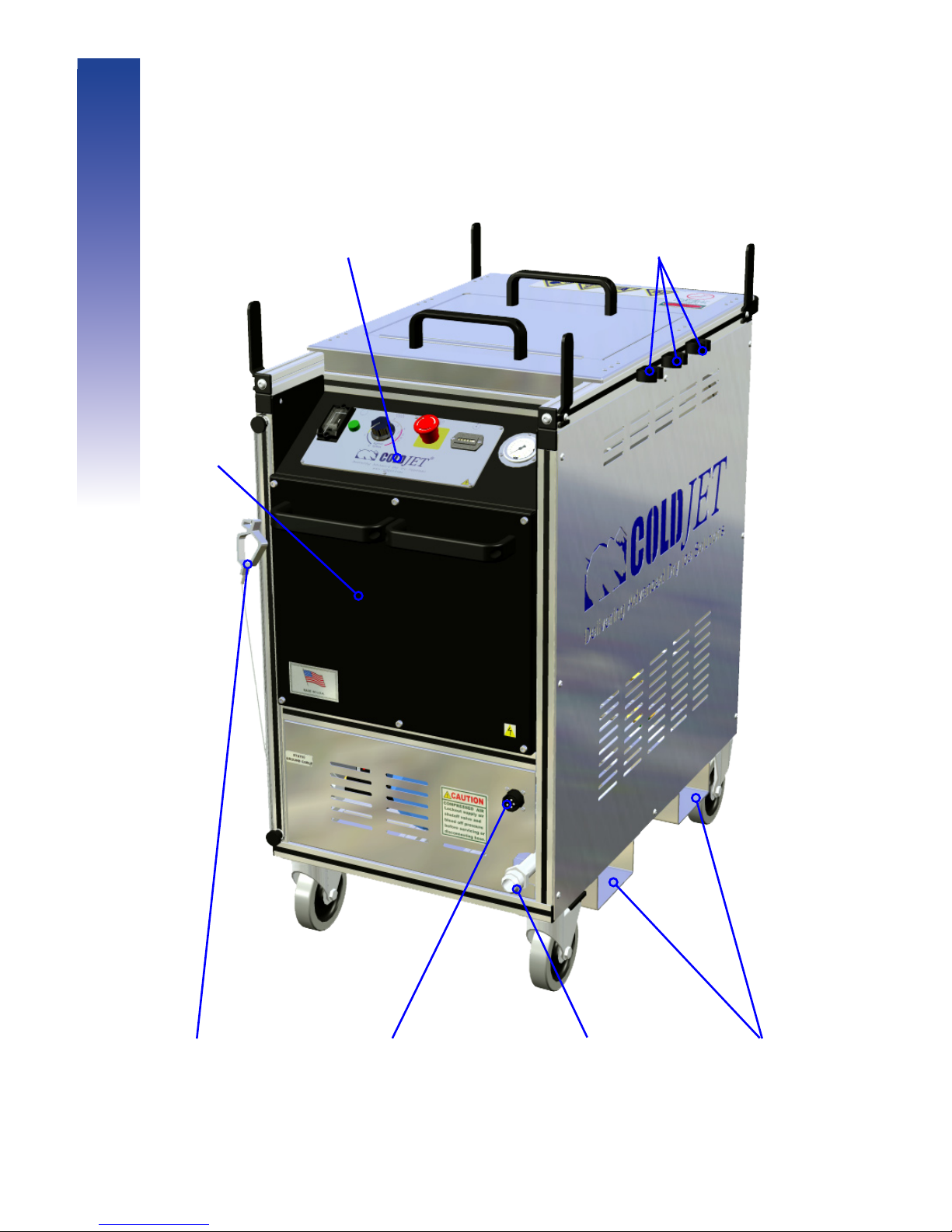
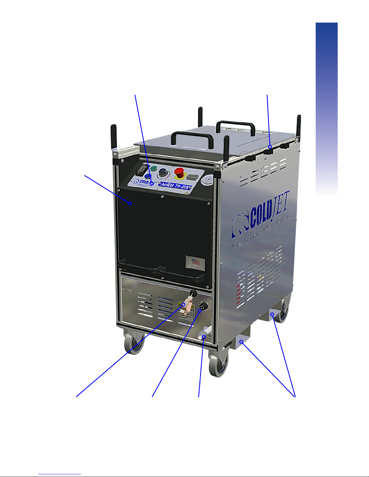
Blast Cable
Connector
Static Ground
Cable
Blast Hose
Connector
Control Panel
Fork-Lift
Tubes
Nozzle Hangers
AeRO 75 Front View
Component Guide
Electrical
Enclosure
(SERVICE ONLY)
Page 17
17
Blast Cable
Connector
Static Ground
Cable
Blast Hose
Connector
AeRO 75-DX Front View
Electrical
Enclosure
(SERVICE ONLY)
Control Panel
Fork-Lift
Tubes
Nozzle Hangers
Component Guide
Page 18
18
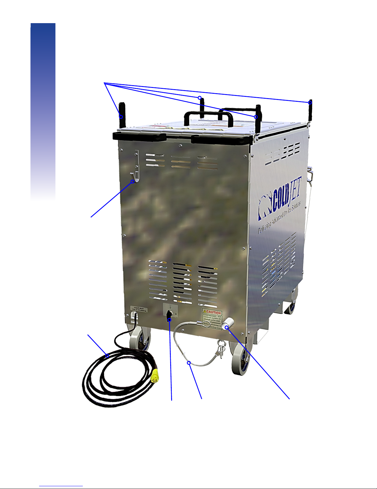
AeRO 75 Back View
Bleed
Valve
Air Supply Hose
Connect
AC Power
Cord
Whip
Check
Power Cord
Hanger
Hose
Hangers
Component Guide
Page 19
19
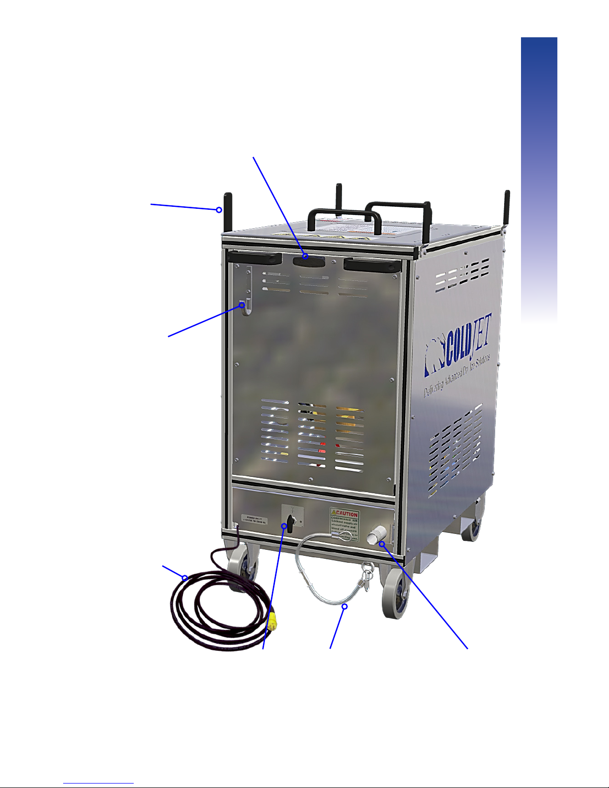
Bleed
Valve
Air Supply Hose
Connect
AC Power
Cord
Whip
Check
Power Cord
Hanger
Hose
Hangers
Hopper Release
Handle
AeRO 75-DX Back View
Component Guide
Page 20
20
Component Guide
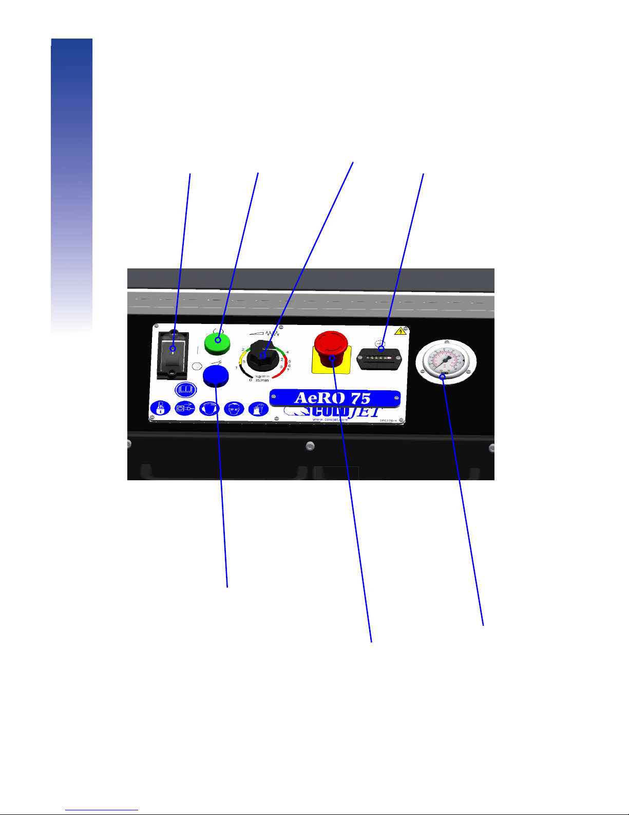
Power
Indicator
Power
Switch
Feed Rate
E-Stop
Hour
Meter
Pressure
Gauge
Machine Active light - When light
is on machine is ready to blast
(the hopper access door being open
is an example of the light being off).
Control Panel
Page 21
21
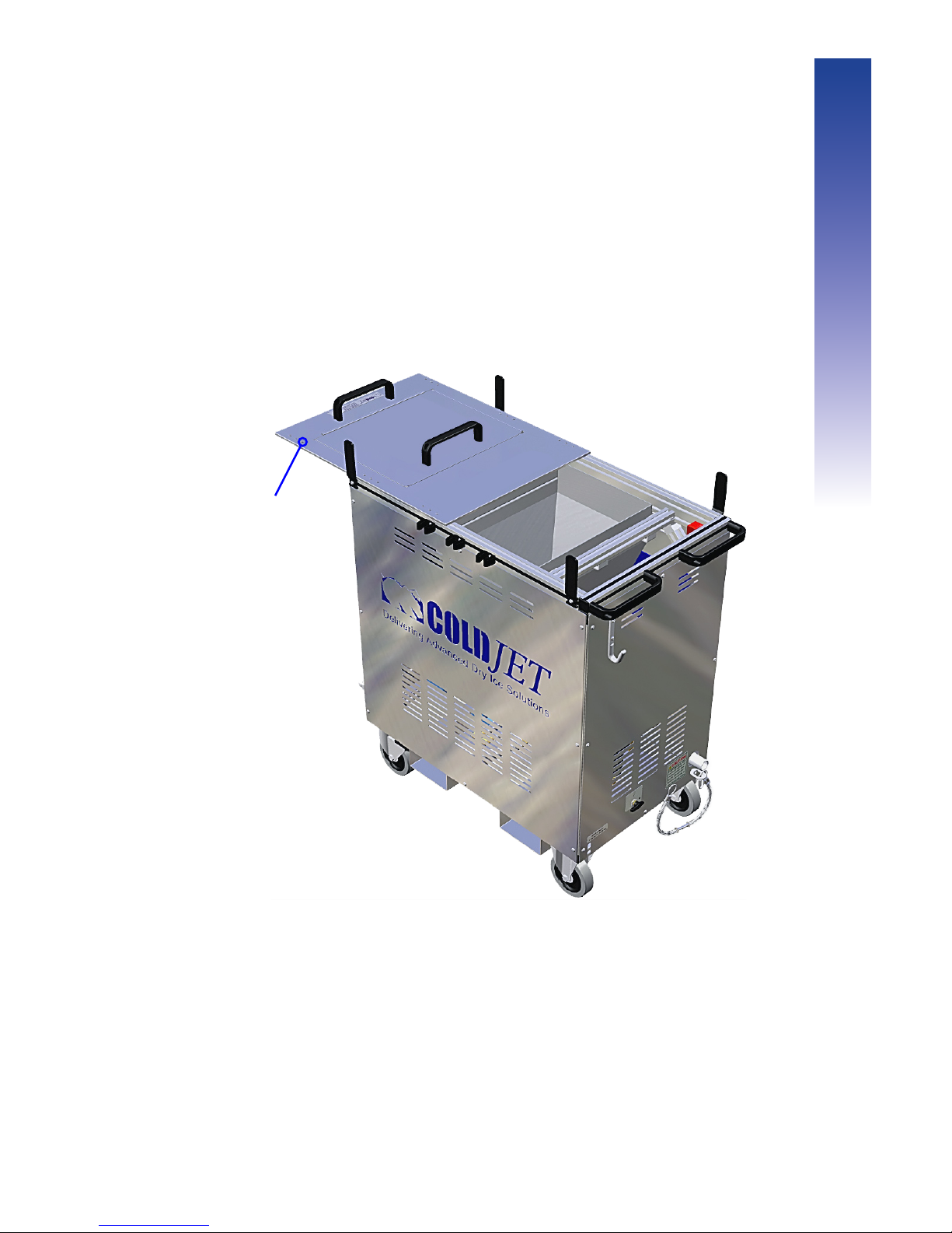
Component Guide
Hopper Access Door
- Used for accessing
hopper for ice or
debris removal. Unit
will not operate when
door is open.
Hopper
Page 22
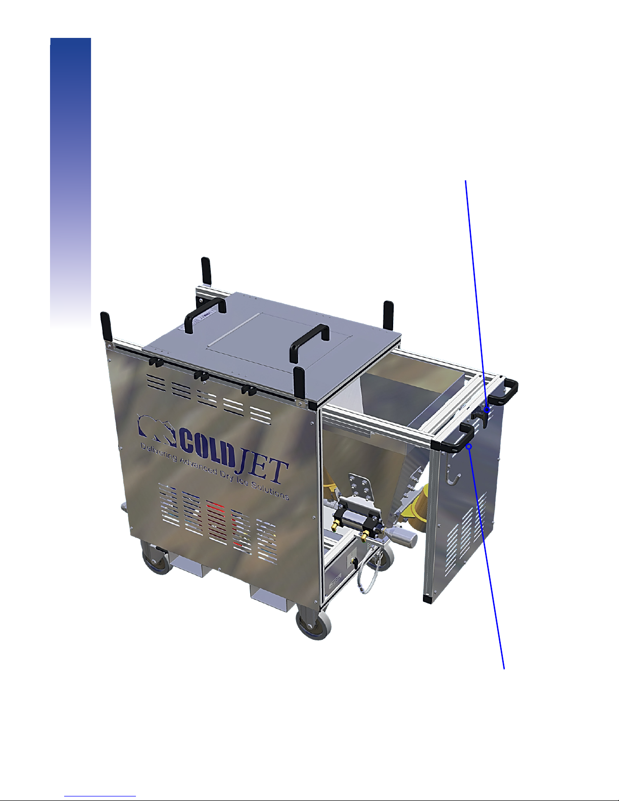
22
1. Rotate release handle
counter-clockwise.
2. Slide out hopper.
Component Guide
Slide Out Hopper (AeRO 75-DX Only)
Page 23
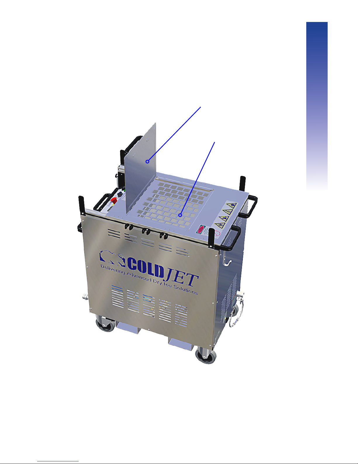
23
Fill Lid.
Used for adding ice.
Metal Grate Prevents large debris from
entering the hopper.
Component Guide
Top
Page 24
24
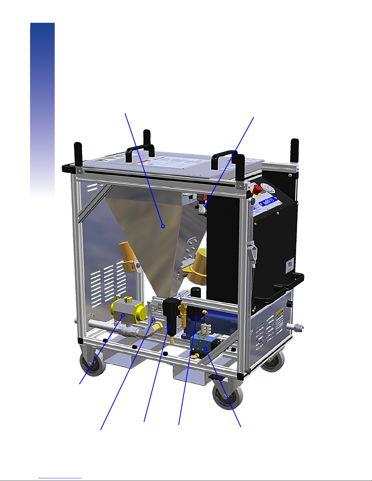
Component Guide
Inside (Standard Conguration)
Air Filter
(Pneumatic
Controls)
Airflow
Actuator &
Blast Valve
Hopper Assembly -
Includes two Vibrators and a
Pneumatic Thumper.
Control
Valves
Regulator
(Pneumatic
Controls)
Safety Switch -
Disables the system
when the door is
open.
Feeder
Page 25

25
Component Guide
Inside (Optional Regulator Conguration)
Optional Inline Pressure Regulator -
Used for precise blast air pressure control.
Air Pressure Knob - Used to set the
blast air pressure to the desired value
by turning the knob prior to blasting.
Page 26

26
Page 27
27
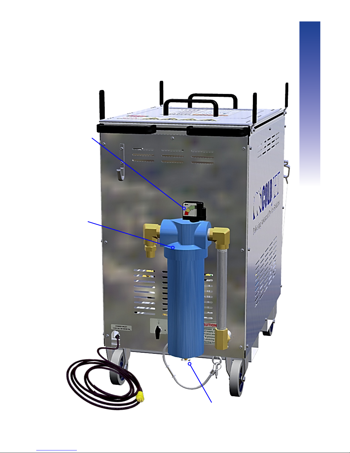
Drain Valve - Used to
drain excess water.
Differential
pressure
gauge
- Indicates if
the filter needs
changing.
Air Filter
- Used
to extract
moisture and
dirt from the
supply air.
Optional (Coalescing/Particulate Air Filter)
Component Guide
Page 28
28
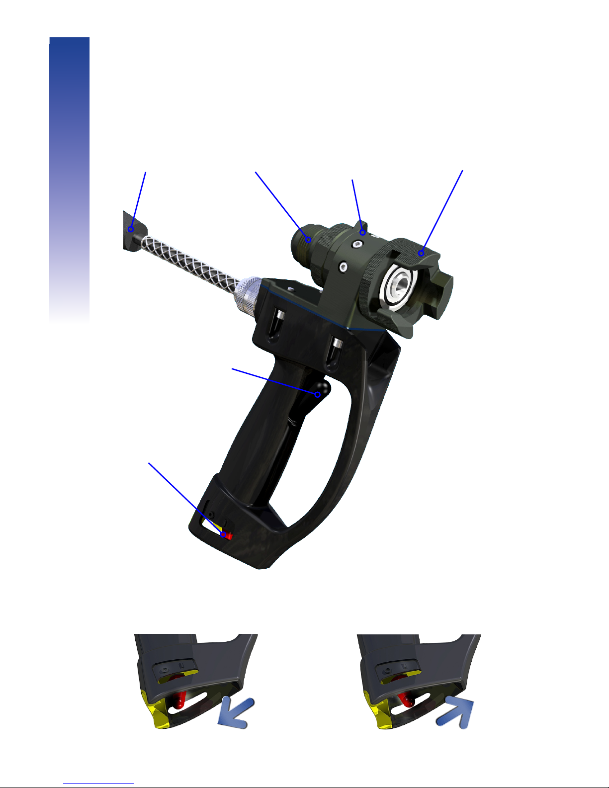
Safety ON
Safety OFF
Retention
Collar
Rotation Stop
Protects blast cable from
damage
Trigger
Also breaks up ice if
pressed rapidly
JICM
Connector
Blast Cable
Connector
Safety Switch
Component Guide
Single Feed Blast Applicator
(AeRO 75 Only)
Page 29
29
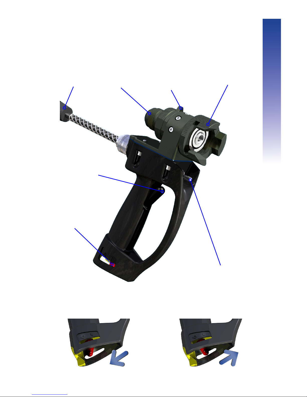
Safety ON Safety OFF
Retention
Collar
Rotation Stop
Protects blast cable from
damage
Trigger
Also breaks up ice if
pressed rapidly
JICM
Connector
Blast Cable
Connector
Tri-Mode Speed Control
Up - Sets speed to 2/3 of Max
Middle - User Set Speed
Down - Purge (removes nozzle clogs)
Safety Switch
Component Guide
Tri-Mode Blast Applicator
(AeRO 75-DX Only)
Page 30

30
Page 31

31
Operation
Page 32
32
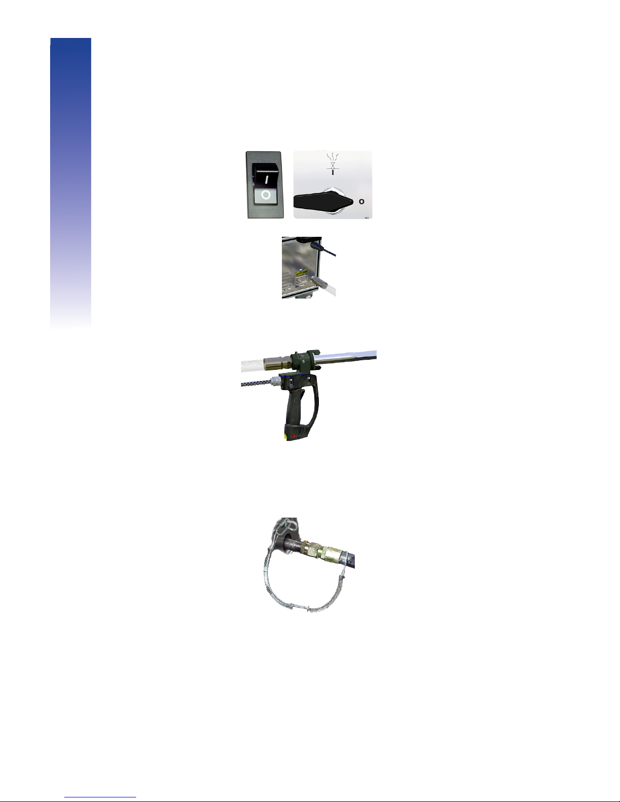
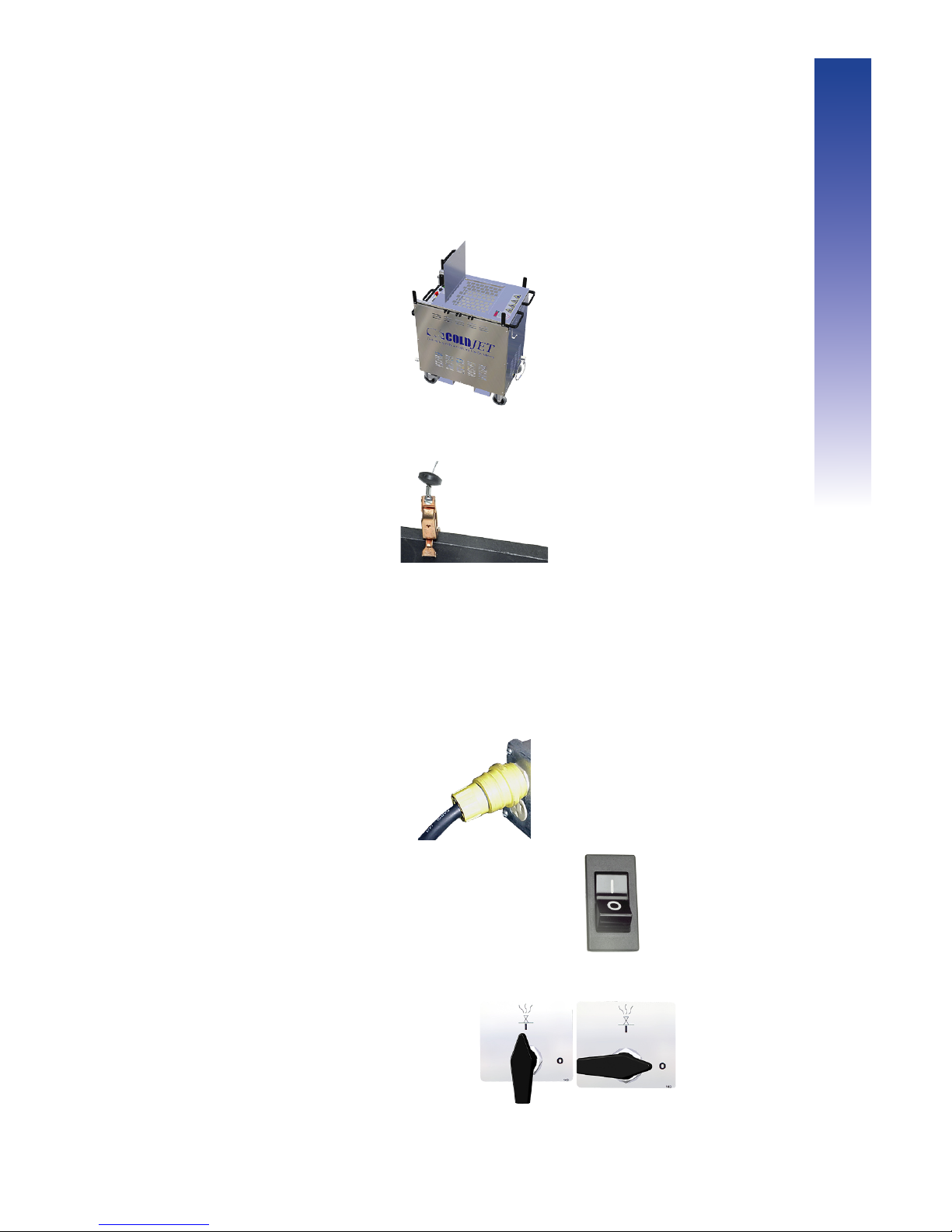
1 Make sure the Power Switch and bleed valve are in the OFF (O)
position.
2 Attach the blast hose and the control cable to the machine.
3 Securely attach the applicator to the blast hose and control cable.
Make sure the Rotation Stop is facing UP.
Verify that a nozzle is locked into the Blast Applicator.
4 Attach the whip-check to the air supply hose and extend it as far as
possible on the air hose.
Attach the Air Supply Hose to the inlet air pipe on the back of the
machine. (Check the data plate for the operating pressure range).
Starting Up
Operation
Page 33
33
5 Make sure the hopper is dry, clean, and free of debris.
6 Connect the Static Ground Cable to the material to be cleaned or to
an electrically conductive supporting structure of the material.
7 Turn on the air compressor, and allow the air supply hose to pressurize.
Check for leaks.
8 Plug the power cord into an electrical outlet. If an extension cord is
necessary, it must comply with the power requirements of this unit and
all governing electrical codes (Check the data plate for the operating
voltage range).
9 Turn the Power Switch to the ON (I) position.
10 Turn the Bleed Valve ON (I) to drain water out of the filter, then turn it
OFF (O) to close it.
Operation
Page 34
34
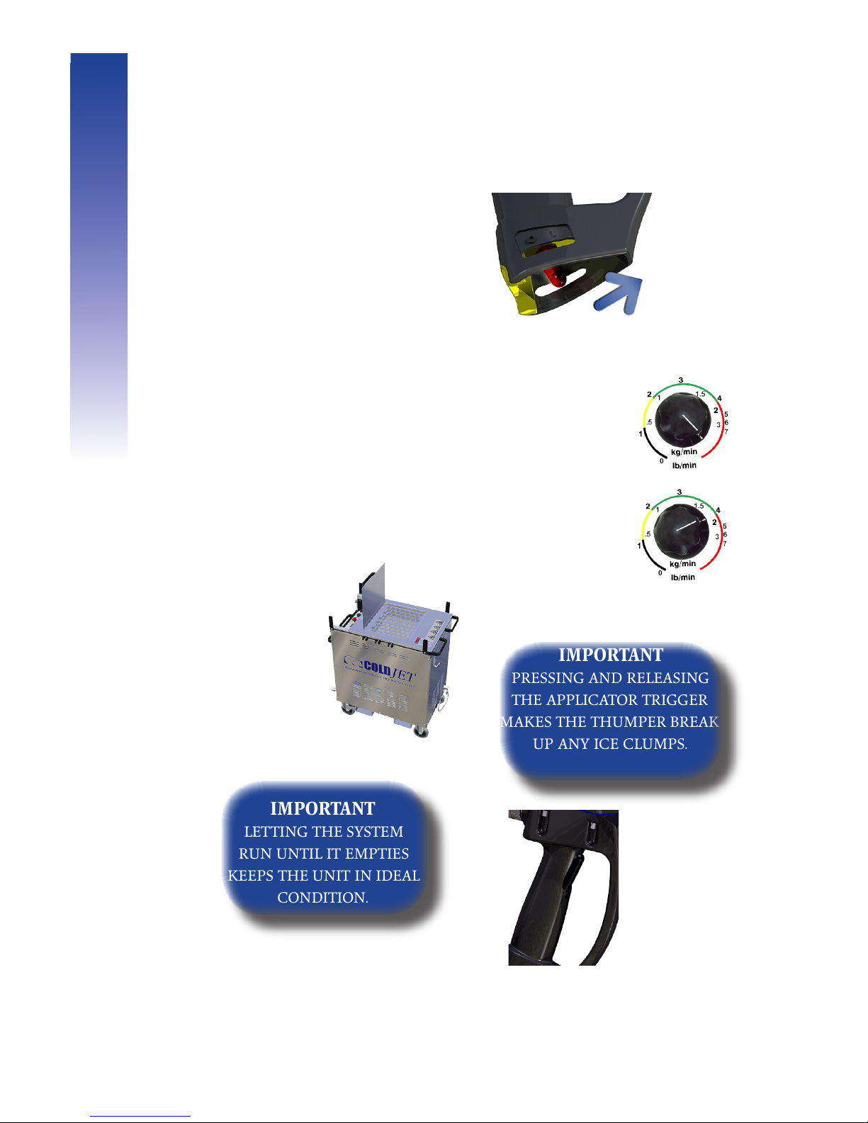
1 Push the Applicator Safety Switch
forward.
2 Purge the system by blasting with air
for 1 min.
How to Purge:
Before loading the pellets into the hopper, turn the feed
control to its maximum setting and pull the trigger.
After purging, return the feed control to the desired
blast setting.
3 Pour the pellets into the hopper.
4 Close the Fill Lid.
5 Squeeze the Applicator trigger to blast.
If desired push the speed switch up to increase the feed
rate to clean tough spots (AeRO 75-DX ONLY).
IMPORTANT
Pressing and releasing
the aPPlicator trigger
makes the thumPer break
uP any ice clumPs.
IMPORTANT
LETTING THE SYSTEM
RUN UNTIL IT EMPTIES
KEEPS THE UNIT IN IDEAL
CONDITION.
Blasting
Operation
Page 35
35
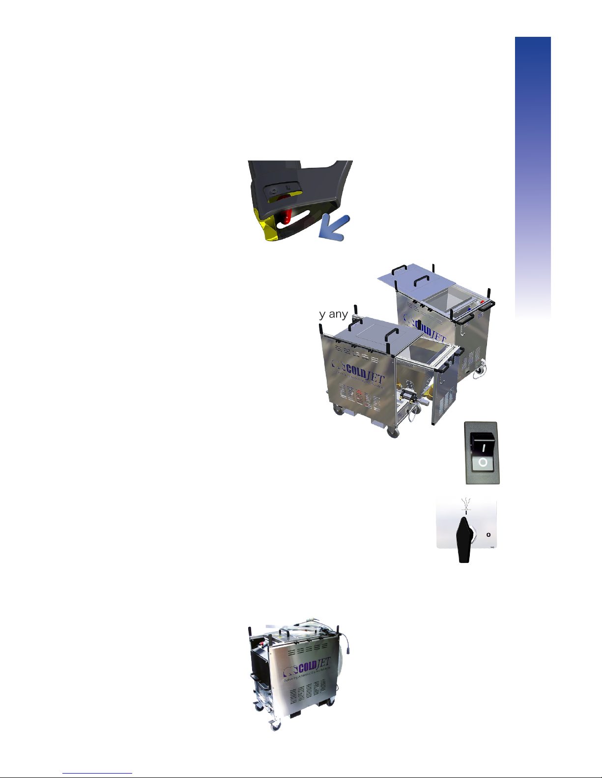
1 Stop blasting and push the safety switch back. (This activates the
safety).
2 For the AeRO 75 slide open the hopper
access door and scoop out the remaining
dry ice from the hopper. For the AeRO 75DX, just slide the hopper out to empty any
remaining ice.
3 Turn OFF the compressed air supply.
4 Turn the power switch OFF (O) to shut off the power.
5 Turn the Bleed Valve ON (I) to evacuate all remaining
pressure.
6 If open, close the Fill Lid.
7 When the air hose is fully depressurized, disconnect all electric cables,
then the hoses, and wrap them around the hose hangers.
Operation
Shutting Down
Page 36

36
Page 37

37
Maintenance
Page 38
38
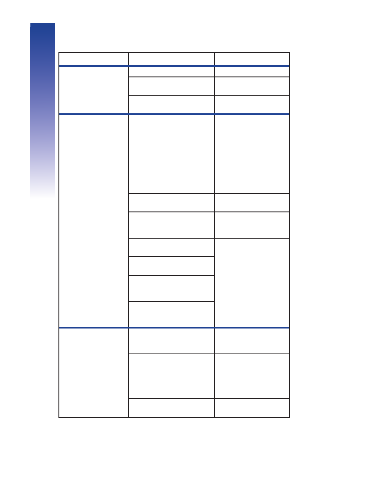
For additional help contact our Customer Support hotline:
+1-800-777-9101 (+1-513-576-8981)
Problem Check This Solution
Machine will
not start
GREEN light is
not on
Is the unit plugged in? If NO...Plug Unit in.
Is the power switch in the
ON (I) position?
If NO...Push power
switch to I.
It still will not start up? Call Cold Jet for support.
Machine will
not blast
Is the machine active light
(the BLUE light) on?
If NO...
Close the hopper access
door and reset the Estop. Also make sure
the slide-out hopper is
latched closed (DX only).
If the above doesn't work
then check fuses FU1
& FU2
Is the applicator safety
switch pushed back?
If YES...Flip the switch
forward.
Is the optional Coalescing
Filter gauge redlining?
If YES...Immediately
replace the filter element.
Is the air supply connected
and the air supply on?
If YES...The nozzle may
be clogged, blast with air
only to unclog it.
Is the air supply gauge
showing pressure?
Is the optional pressure
regulator open and
displaying pressure?
Is applicator cable connected
to the machine and the
applicator?
Machine blasts
AIR but NOT
pellets
Set feeder speed and check
the thumper for movement.
If no movement see
below.
Do Vibrator fuses FU3 and
FU4 glow orange?
If YES...Replace the
fuse(s) that glows
orange.
The Hopper may be clogged.
Squeeze the trigger to
break up ice clumps.
A foreign object may be
lodged in the feeder.
Call Cold Jet for support.
Maintenance
Troubleshooting
Page 39
39
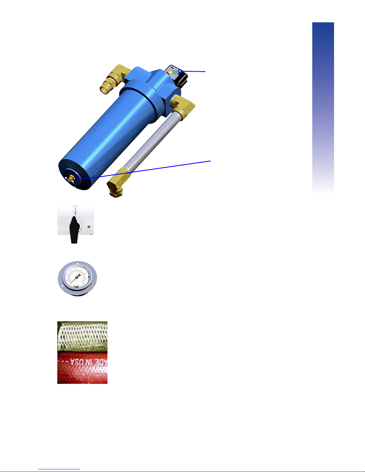
Drain water out of the air filter before
using the machine. (Turn the bleed valve
ON (I) to drain the water).
While in operation check the pressure
gauge for damage.
Check the air and blast hoses for
damage, like cuts or scuff marks.
Drain the water out of the
optional Coalescing filter by
opening the drain valve at
the bottom of the filter.
Make sure the gauge is in the
GREEN. If not then change
the filter element to avoid
damage to the machine
Daily Maintenance
Maintenance
Page 40
40
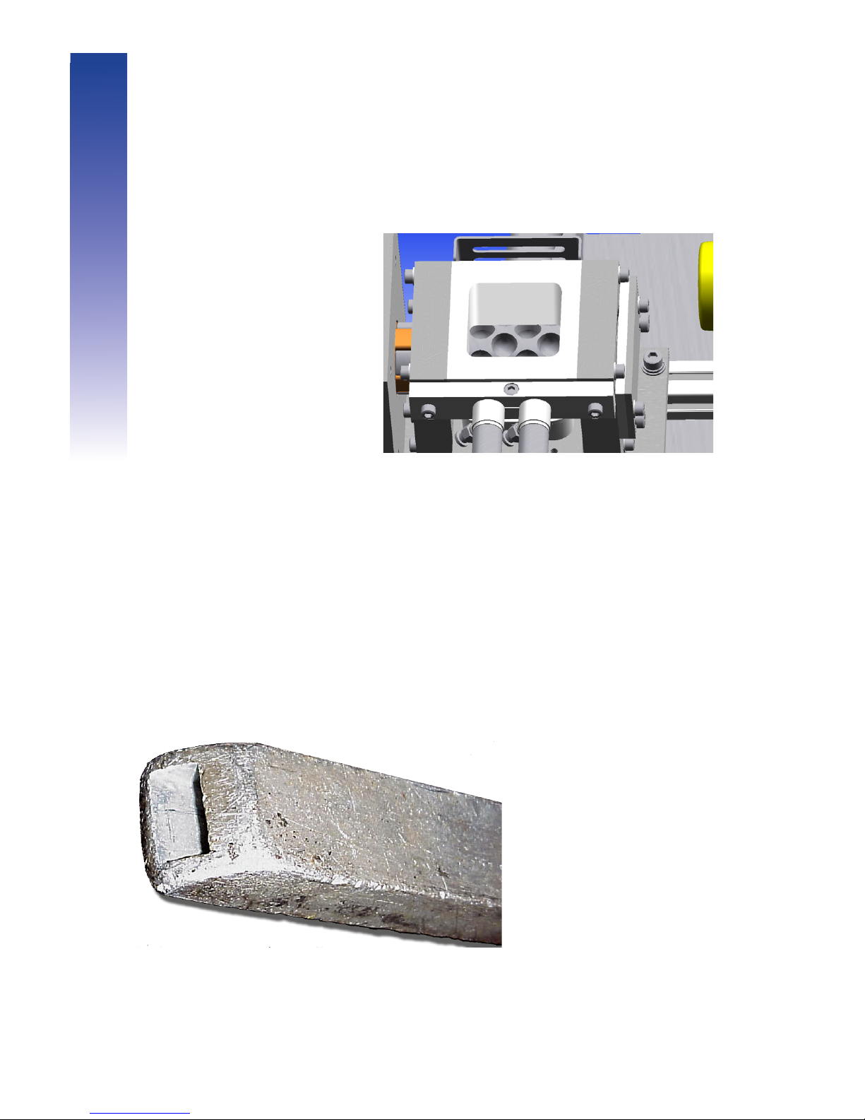
Make sure the nozzle airflow exit end
is not deformed or burred.
Look through the hopper to
check the rotor for nicks or
gouges. (Use a flashlight).
Maintenance
Weekly Maintenance
Page 41
41
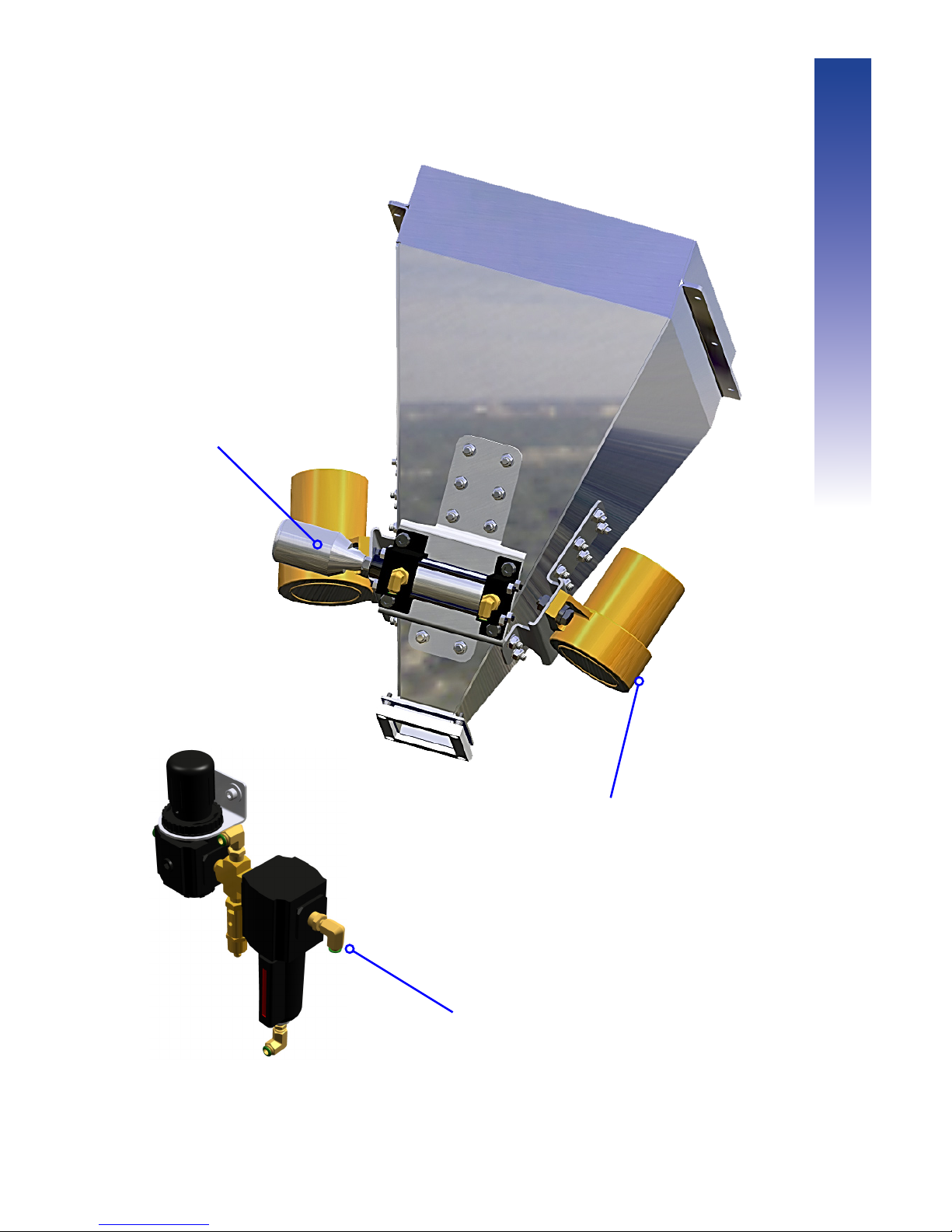
Check the
thumper
for worn or
damaged
parts and
also check
for loose
fittings.
Check the Vibrators for
vibration. Also check
the two mounting bolts,
on each vibrator, to
verify they are secure.
Check the Air Filter by
unscrewing the base a 1/4
turn clockwise.
Monthly Maintenance
Maintenance
Page 42

42
1 Check pads and rotor
2 Check pneumatic air lines
3 Check thumper and vibrator assemblies
4 Check condition of power cord
5 Check all lights
6 Check the pressure gauge
7 Check static ground cable
8 Inspect hoses for damage
9 Replace the air filter element
10 Check the accessories
11 Safety test the unit
12 Check all valves
If you are not an authorized Cold Jet Service Technician,
please call to schedule service.
+1-800-777-9101 or +1-513-576-8981 or
email: [email protected]
(Europe: 32 (0) 13 53 94 47, Office Hours: GMT +1.00 or
email: [email protected])
Maintenance
Biannual Maintenance
Page 43

43
Appendix
Page 44
44
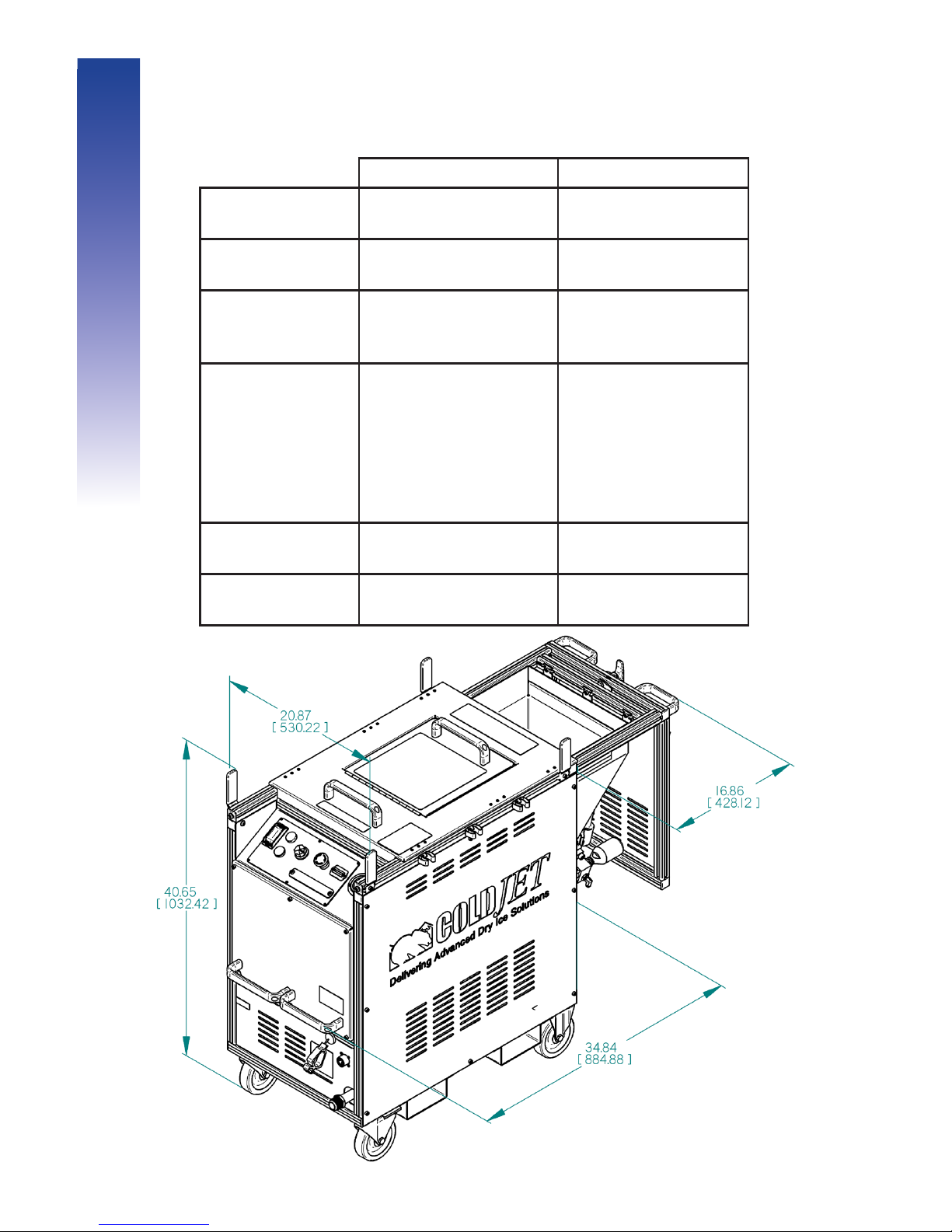
AeRO 75 AeRO 75-DX
Weight (empty):
295 lbs.
(134 kg.)
315 lbs.
(143 kg.)
Pellet Capacity:
75 lbs.
(34 kg.)
75 lbs.
(34 kg.)
Pellet Delivery
Rate:
Variable From:
0 - 7.1 lbs/min
(0 - 3.2 kg/min)
Variable From:
0 - 7.1 lbs/min
(0 - 3.2 kg/min)
Power
Requirements:
100 - 140 volts AC
single phase
(50/60 Hz) 9 amps
or
200 - 240 volts AC
single phase
(50/60 Hz) 4.3 amps
100 - 140 volts AC
single phase
(50/60 Hz) 9 amps
or
200 - 240 volts AC
single phase
(50/60 Hz) 4.3 amps
Feeder Drive:
1/2 Hp. AC Motor
1,750 RPM
3/4 Hp. AC Motor
1,750 RPM
Available Blast Air
Pressure:
30 - 140 psi.
(2 - 9.66 bar)
30 - 300 psi.
(2 - 20 bar)
Specications
Appendix
Page 45
45
Appendix
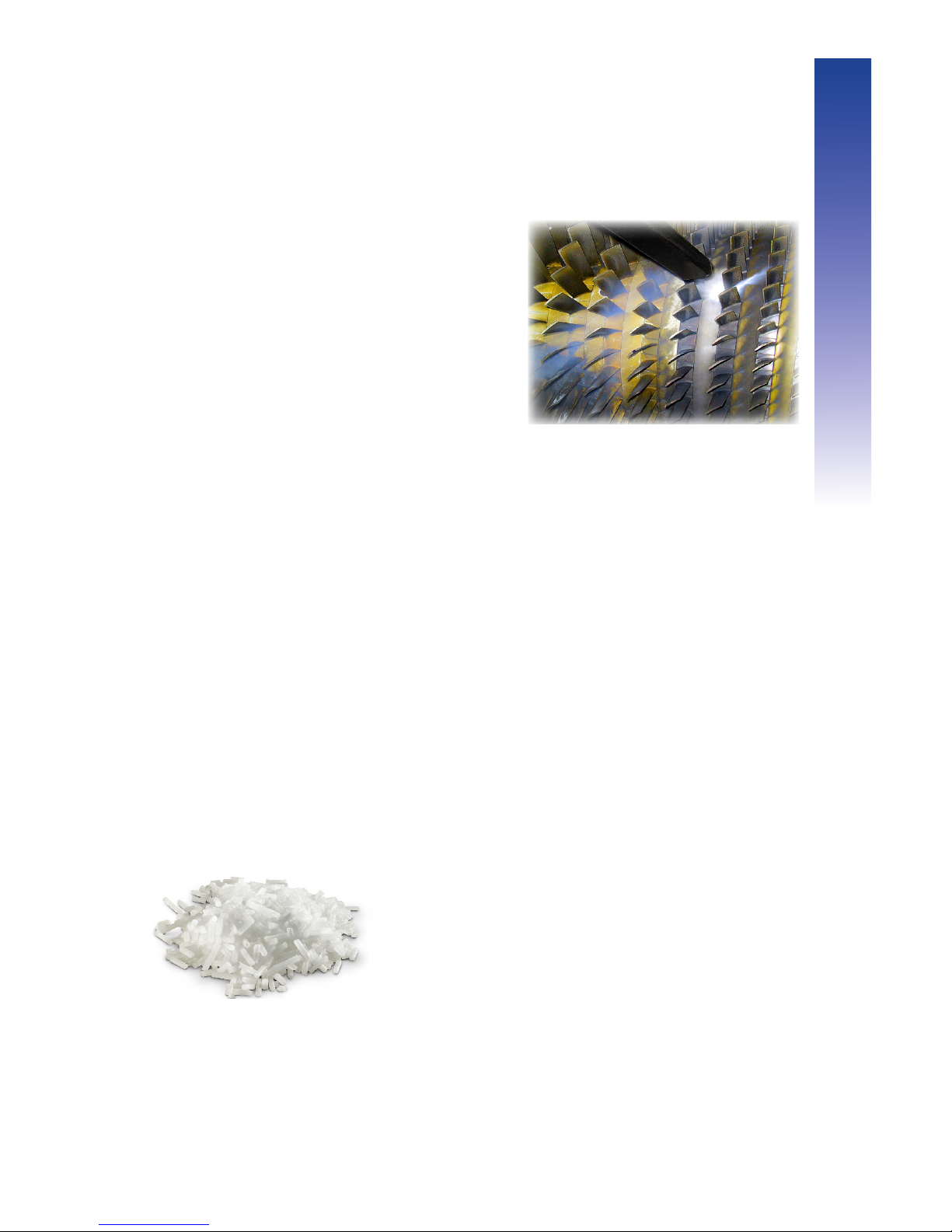
Handling Pellets
Blasting Techniques
• POSITION the blast hose for maximum
maneuverability BEFORE blasting.
• DO NOT kink the blast hose.
• HOLD nozzles PERPENDICULAR
to the surface for fastest cleaning
(recommended for most applications).
• OPTIMUM STAND OFF DISTANCE is
2 in (5 cm) for most nozzles.
• NEVER ALLOW foreign objects to
enter the hopper!
• DO NOT abuse the blast applicator or
cable.
• BLAST with AIR ONLY for 1 minute
after breaks (to melt any water ice
build-up inside the blasting unit).
• SLIDE hopper access door open to
empty pellets.
• HOPPER SHOULD BE EMPTY
BEFORE REFILLING.
Tips
• KEEP pellet boxes and fill lid CLOSED at all
times.
• DO NOT use powdery or clumped pellets.
• USE a plastic scoop (not metal) to fill hopper.
• PELLET-BOX liner fragments should not
enter hopper.
• DO NOT BREAK THE SEAL on pellet box
until pellets are needed.
• USE pellets as soon as possible after
opening the box.
• STORE pellet boxes out of direct sunlight.
• DO NOT use pellets larger than 1/8-inch
(3mm) in diameter.
Page 46

46
Appendix
The Cold Jet AeRO 75 series blast machine works best when the supply
air is free of any debris and has a dew point of -40°F (-40°C).
If Using Plant Air (Central Compressed Air System)
Manufacturing plants, with central compressed air systems, should have an
After Cooler and a 2-stage coalescing filter assembly downstream of the
receiver tank. Hot metal pipes are an indication this is needed.
To verify that the plant air system is adequate for the AeRO 75 (75-DX) the
air compressor needs to produce an air volume 10% greater than the blast
machine's maximum air volume...in addition to the air volume consumed by
normal plant operation.
To determine adequate air volume, blast while watching the pressure
gauge.
• If the gauge drops slowly the compressor is insufficient.
• If the gauge drops quickly there is a restriction or the pipe is too small.
• If the gauge stays steady then the compressor and piping are
adequate.
To maintain adequate pressure to the AeRO 75 (75-DX):
• From the air compressor to 50 ft (15 m) use a flexible 1 in (25 mm) air
hose (preferably the hose supplied with the machine).
• From the air compressor to beyond 50 ft (15 m) make sure the pipe is
1 in (25 mm) in diameter before attaching the air hose.
If an air drop isn’t used much, water and rust will collect in the line. Before
plugging into the air supply, purge the line, to prevent contamination of the
AeRO 75 (75-DX).
Blast Air Quality
Up to 140 psi (9.6 bar)
Page 47

47
Appendix
If Using Portable Air (minimum of 185 cfm - 5.6 m
3
/min)
Portable diesel air compressors are mainly used for shop tools, not dry ice
blasting units and are therefore not able to cool or remove air moisture.
An after cooler with a 15°F (-9°C) approach is required to reduce the
discharge air temperature 180°F (82°C) to within 15°F (-9°C) of ambient air
temperature.
Without the after cooler, the following will occur:
1 Incoming air moisture will rapidly cool and freeze at the AeRO 75 (75-
DX) feeder.
2 Water ice will accumulate in the feeder, distorting the air flow and seal.
3 Water ice buildup will continue inside the blast hose, to the nozzle.
4 Water ice will break off inside the hose and lodge in the nozzle,
causing a jam.
5 Water ice, may exit the nozzle, and damage the target surface.
For the above reasons, an after cooler and moisture trap/filter must be
used.
If blasting continuously, use an air dryer to further reduce the air moisture
(dew point). Desiccant dryers produce a dew point of -40°F (-40°C),
resulting in a dew point low enough for continuous blasting.
To verify the compressor is of adequate size for the AeRO 75 (75-DX) the
air compressor needs to produce an air volume 10% greater than the blast
machine's maximum permissable air volume.
To determine adequate air volume, blast while watching the pressure
gauge.
• If the gauge drops slowly the compressor is insufficient.
• If the gauge drops quickly there is a restriction or the pipe is too small.
• If the gauge stays steady then the compressor is adequate.
To maintain adequate pressure, the hose size from the compressor to the
AeRO 75 (75-DX) needs to be 1 in (25 mm) in diameter.
Page 48

48
Appendix
• Call +1-800-SEND-ICE (+1-800-736-3423)
or
+1-877-437-9423
• RETURN empty ice boxes promptly after use.
• Pellets are made using FOOD GRADE QUALITY dry ice.
•
Manufacturers of dry ice are located throughout the world for
the recommended manufacturer in your area call +1-800-777-9101
(Europe: 32 (0) 13 53 47) or e-mail [email protected]
(Europe: [email protected])
Cold Jet Services
• Equipment Upgrades
• Preventative Maintenance Repairs,
and Refurbishing
• Training
• Parts and Accessories
• Spare Parts Kits
• Extended Service Plans
• Equipment Rental
• Contract Cleaning Services
• Engineered Solutions
• 24-Hour Technical Phone Support
+1-800-777-9101 or 1-513-576-8981
(Europe: 32 (0) 13 53 95 47, Office Hours: GMT +1.00)
• Email Technical Support:
Ordering Pellets
Page 49
49
Appendix
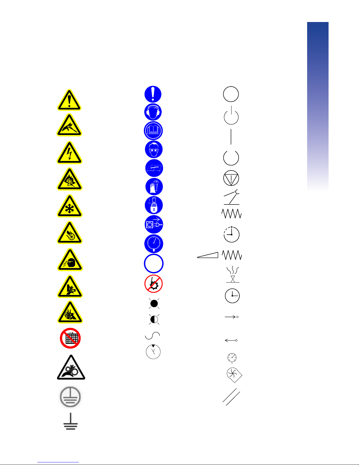
Machine Symbols
General mandatory
action
Wear ear protection
Read operator manual
Read service manual
Wear eye protection
Wear safety gloves
Lock out in
De-energized state
Unplug before opening
No foreign objects
CO
2 only
Maintain safe pressure
Skin puncture from
pressurized air jet
Electrical shock
or electrocution
Loud noise
Extreme cold
Hand cut from
impeller blade
Flying debris
Hand crush
from side
Explosive release
of pressure
Do not operate with
guard removed
Alternating current
Hydraulic motor
Light on
Light flashing
CO2
General danger
On
Off
Standby
Emergency stop
Ready
Applicator ready to
blast
Feed
Variable feed
Effect or action to a
reference point
Piston extrusion
Effect or action away from a
reference point
Piston retraction
Elapsed time display
Programmable timer
Hourmeter
Clock
Time switch
Timer
Reset
Bleeding
Rotary knife
Pressure
High chamber pressure
Moving Parts
Protective
Ground
Ground Test
Point
Page 50

50
Appendix
Page 51

51
Warranty Information
Cold Jet® LLC (“CJ”) warrants its products (“Equipment”) provided under this
Agreement to be free from defects in materials and workmanship for a period
of 12 months, under normal use, maintenance and service as stipulated in the
Operator’s Manual. CJ warrants that the equipment will be in good working order
on the Date of Shipment and will conform to CJ’s official published specifications.
The warranty period is 12 months for CJ manufactured Equipment. Original
Equipment Manufacturers’ warranties provided by CJ on equipment purchased
under this Agreement not manufactured by CJ will be passed through to
the Buyer. The warranty period commences on the Date of Shipment of the
Equipment.
CJ’s liability is limited to repairing or replacing, at its option, any covered part of its
Equipment, which CJ has determined to be defective. Said repair or replacement
will be made by CJ or its authorized representative free of charge to the Buyer,
except for any freight or travel expenses, during the warranty period. Any
replaced part will become the property of CJ. If, after repeated efforts, CJ is
unable to restore its Equipment to good working order, or to replace the defective
parts as warranted, CJ may, at its discretion, replace the Equipment in its entirety.
Any claim must be made to CJ, in writing, within 30 days of discovering the defect
and any claim not made within that period shall be deemed waived or released,
and thus denied.
Warranty service provided under this Agreement does not assume uninterrupted
operation of the Equipment. The suitability of the equipment for the purpose
intended is not included in the warranty.
This warranty shall not apply and CJ shall be neither responsible nor liable for:
a) Consequential, collateral or special losses or damages;
b) Equipment conditions caused by abnormal conditions of use, accident, neglect
or misuse of equipment, improper storage or damages resulting during shipment
as determined by CJ;
c) The replacement of normal wear items, including but not limited to air, blast and
whip end hoses;
d) Deviation from the Equipment’s prescribed maintenance programs, replacement
parts, operating instructions, specifications or other terms of sale;
e) Labor charges, loss or damage resulting from improper operation, maintenance
or repairs made by person(s) other than CJ or CJ-authorized service
representatives;
f) Improper application of the product. In no event shall CJ be liable for claims in
excess of the purchase price, whether there is a breach of contract or warranty
claim of negligence or negligent manufacture.
THIS WARRANTY IS THE SOLE WARRANTY OF CJ AND ANY OTHER
WARRANTIES, EXPRESS, IMPLIED IN LAW OR IMPLIED BY FACT, INCLUDING
ANY WARRANTIES OF MERCHANTABILITY AND FITNESS FOR PARTICULAR
USE, ARE HEREBY SPECIFICALLY EXCLUDED.
Page 52

 Loading...