


®
PLT 60
Operator Manual
Original Instructions [English] September 2019

Copyright © 2019 Cold Jet, LLC
All rights reserved. Printed in the USA.
Due to continued product development this information may change without notice. The
information and intellectual property contained herein is condential between Cold Jet and the
client and remains the exclusive property of Cold Jet. If you nd any problems in the documentation,
please report them to us in writing. Cold Jet does not warrant that this document is error-free.
No part of this publication may be reproduced, stored in a retrieval system, or transmitted in any
form or by any means, electronic, mechanical, photocopying, recording or otherwise without the
prior written permission of Cold Jet.
This manual reects the product conguration as was current at the time of its writing. An item’s
display in this manual does not guarantee the item’s availability at any time in the future. Images
shown are for representation purposes only. Products may vary from the images displayed. Cold Jet
is not liable for typographical errors or changes to specications presented.
ii

Contents
Introduction ........................................................................................................................................................1
Safety .................................................................................................................................................................... 3
PLT 60 System Description .............................................................................................................................7
Operations ........................................................................................................................................................17
Cold Jet CONNECT™ ........................................................................................................................................33
Maintenance .....................................................................................................................................................35
Warranty ............................................................................................................................................................39
EU Declaration of Conformity .......................................................................................................................41
Technical Schematics......................................................................................................................................43
Contact Information ........................................................................................................................................50
iii

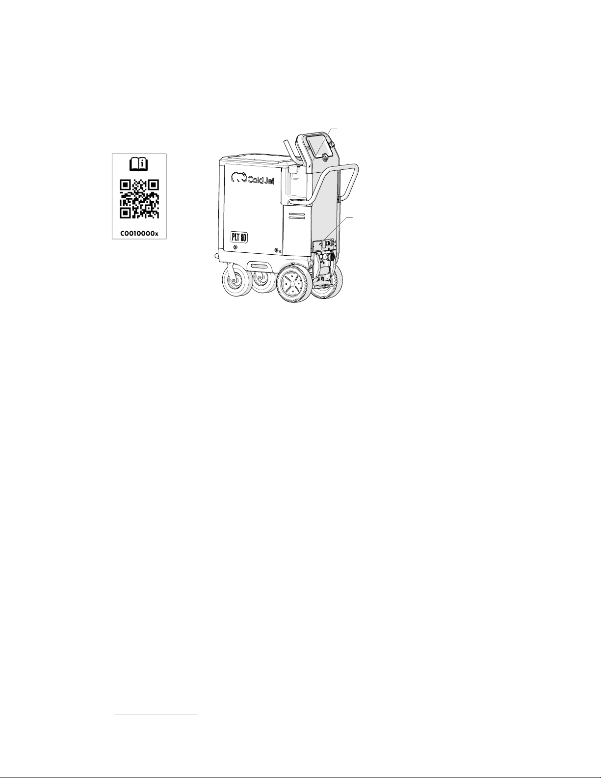
System Identication
Locate the tag(s) for this machine and record the information provided in the spaces below. To view
documentation for your machine, scan the QR code:
QR Code
Data Plate
ASSEMBLY No. _____________________________________________________________________________________________________
SERIAL No. _________________________________________________________________________________________________________
ELECTRICAL No. ____________________________________________________________________________________________________
AC VOLTS ___________________________________________________________________________________________________________
PHASE _______________________________________________________________________________________________________________
FREQUENCY ________________________________________________________________________________________________________
AMPS ________________________________________________________________________________________________________________
MAX OPERATION PRESSURE ______________________________________________________________________________________
MOTOR KW _________________________________________________________________________________________________________
Mo./Yr. ______________________________________________________________________________________________________________
SCCR _________________________________________________________________________________________________________________
Supplier Responsible for the Equipment:
Cold Jet, LLC
455 Wards Corner Road
Loveland, Ohio 45140 USA
Phone: +1-800-777-9101
Website: www.coldjet.com
v


Introduction
About This Manual
This manual should be kept with the machine and be readily accessible to machine operators and
maintenance personnel.
This manual contains information on the safety, transportation, operation and maintenance of this
machine.
The graphics used in this manual may show machine details that may be dierent than the actual
machine. Components of the machine may have been removed for illustrative purposes or the
continuing improvement of the machine’s design may cause changes that are not included in this
publication.
The owner of this machine is responsible for verifying the operator of this machine is properly
trained and understands the contents of this manual.
About The PLT 60
This machine combines patented technology in a lightweight and compact design that gives the
operator unparalleled control for dry ice cleaning and other applications.
y The Advanced Air-Flow System reduces pressure loss as the air ows straight through the
system which also decreases sublimation and loss of the dry ice particles.
y The Blast Pressure Control System can be regulated digitally from the 7” HMI color screen on
the control panel or certain applicators.
y The SureFlow System with Dynamic Agitation is designed to keep warm air, moisture and
debris out of the hopper while keeping the dry ice owing. The level of dry ice in the hopper
can be monitored from the HMI screen of the control panel or certain applicators.
y The Advanced Direct Drive Feeding System is a two-stage feeding system that improves feed
rate consistency and maximizes dry ice particle integrity.
Environmental Impact
Dry ice is a safe, clean and non-toxic medium approved by the EPA, USDA and FDA. The dry ice used
in this machine is made from reclaimed CO2 generated from other industrial processes.
1


Safety
General Safety Guidelines
This machine is designed to comply with international design standards and the European
Machinery Directives. Therefore, using the machine does not pose a risk to the operator when the
instructions in this manual are followed carefully. However, certain precautions must be followed
during its use. To understand all the necessary precautions, the machine operator must read the
entire manual before operating or performing maintenance on the machine.
Operation and maintenance should only be performed by authorized and trained personnel. Below
are some basic safety guidelines:
y Follow local governing codes to ensure a minimum standard of safety.
y Wear protective gloves, eye protection and hearing protection.
y Operate the machine in a well-ventilated work area.
y Follow the prescribed maintenance schedule (see “Maintenance” on page 35).
y Start up and shut down the machine according to the instructions in this manual.
y Do not operate a machine that is damaged or in disrepair.
y Do not store objects on top of machine hopper.
CO2 Safety
This machine uses dry ice (CO2 in solid form). The temperature of dry ice is -78.9°C (-109°F). Avoid
coming into direct contact with dry ice as it may cause severe tissue damage.
Study the material safety data sheet (MSDS) of dry ice (CO
) supplied with the delivery of dry ice and
2
follow all the recommendations and guidelines listed therein.
Operate the blaster in a well-ventilated work area with continuous CO
-level monitoring. The eects
2
of CO2 are entirely independent of the eects of oxygen deciency. Therefore, CO2 concentrations
at 3-5% causes headaches, fast breathing and discomfort while higher concentrations may cause
unconsciousness, suocation or respiratory arrest. The legal exposure limit set by OSHA is a 0.5%
average over an 8-hour workday and the acute (15 minute) exposure limit set is 3.0%.
Always use a CO
monitoring/alarm system when working with machinery that emits CO2 in a
2
conned room/space.
Electrostatic Discharge
Dry ice blasting may create electrostatic discharge(s). This machine is tted with eective
electrostatic dischargers to prevent injury or damage. Also, the machine must be plugged into a
properly grounded electrical outlet.
It is recommended to avoid operating the machine near explosive or ammable material. Also, use a
plastic shovel when handling dry ice to eliminate any additional static electricity.
3

Safety Labels
The symbols used on the machine were developed by the International Organization for
Standardization (ISO) and are dened below. These symbols may include yellow warnings triangles,
blue mandatory action circles or red prohibited action circles.
Symbol Denition
General Warning
Cold Temperature Warning
Pressurized Material Ejection Hazards
Electrostatic Discharge Warning
Asphyxiation Warning
Wear protective gloves
Wear hearing protection
Wear eye protection
Read operator and maintenance manual
Do not operate without Safeguard Grate/guard in place
No foreign objects allowed inside machine
CO2 is in use
Protective Earth/Ground
4

Symbol Denition
Frame/Chassis Terminal
There may be other safety labels or warning signs on the machine that contain additional
information regarding potential safety hazards not explained in this manual. Operators and
maintenance personnel should familiarize themselves with these safety labels and warning signs.
Replace any safety labels or warning signs if they become damaged, missing or illegible.
Cautions and Warnings
Please review the following cautions and warnings before operating or performing maintenance on
the machine.
CAUTION Read the instructions before using the machine. Only qualied personnel
should operate the PLT 60.
WARNING Ensure adequate ventilation when operating this equipment to prevent the
build-up of carbon dioxide gas. If used indoors or other conned space, a CO
detector should be used to monitor for excessive unsafe levels of CO2 gas and
provide a suitable warning.
2
WARNING Ensure that expended dry ice pellet emissions are not in the vicinity of air
ventilation.
WARNING This machine has been designed for use with 3mm dry ice pellets
recommended by Cold Jet. The use of other cleaning agents or chemicals may
adversely aect the safety of the machine.
WARNING High pressure jets can be dangerous if subject to misuse. The jet must not be
directed at persons, live electrical equipment or the machine itself.
WARNING Do not use the machine within range of persons unless they wear the
personal protective equipment (PPE).
WARNING Do not direct the blast stream against yourself or others in order to clean
clothes or foot-wear.
WARNING High pressure cleaners shall not be used by children or untrained personnel.
5

WARNING High pressure hoses, ttings and couplings are important for the safety of the
machine. Use only hoses, ttings and couplings recommended by Cold Jet.
WARNING To ensure machine safety, use only original spare parts from Cold Jet or
approved by Cold Jet.
WARNING The applicator and applicator hose contain electrical connections. Do not
immerse in water.
WARNING Do not use the machine if a supply cord or important parts of the machine are
damaged, (e.g. safety devices, high pressure hoses, applicator).
WARNING Inadequate extension cords can be dangerous. If an extension cord is used, it
shall be suitable for the environment in which it is used. If used outdoors the
connection has to be kept dry and o the ground. It is recommended that this
is accomplished by means of a cord reel which keeps the socket at least 2.4
inches (60 mm) above the ground.
WARNING Always switch o the main disconnecting switch, or unplug the blaster power
cord when leaving the machine unattended.
6

PLT 60 System Description
The PLT 60 will be supplied with the Performance Kit. This applicator kit is as follows:
y 3/4 in or 1 in Performance Applicator
y Performance nozzle
y Nozzle handle
y 1 in air supply hose 25 ft (7.62 meters)
y 3/4 in or 1 in Hybrid-Flex blast hose 20 ft (6.09 meters)
y Hose carrier
y Hose wrap
7

PLT 60 Data
Dimensions
Weight
Blast Medium
Hopper Capacity
Power
Requirement
Air Supply Pressure
Range
Air Flow Range
Air Flow Path
Blast Pressure
Range
Variable Feed Rate
Air Hose
Blast Hose
38.75 x 18.98 x 45.03 in (98.43 x 48.21 x 114.38 cm)
233 lb (105.69 kg)
3 mm dry ice pellets
60 lb (27 kg)
110/230 VAC (50/60 Hz) = AMPS 4.3
40-250 psi (2.8 - 17.2 bar)
50-165 cfm at 80 psi (1.4-4.7m3/min at 5.5 bar)
1 in (25 mm) straight-through
35-250 psi (2.4-17.2 bar)
0-6 lb/min (0-2.7 kg/min)
1in (25.4 mm) Air Supply Hose
¾ in (19 mm) Advanced combination material ex hose
1in (25.4 mm) Advanced combination material ex hose
Applicator
Control/Display
Communication
Integration
(Optional)
Noise Level
¾ in (19 mm) Performance Applicator with on/o; air only; light control
1in (25.4 mm) Performance Applicator with on/o; air only; light control
7 in (17.7 cm) LCD screen with rotary encoder dial
IoT connectivity via a cellular 3G/LTE Global and Cold Jet CONNECT™
Automation/Integration capable with PLC controlled system (Modbus protocol) by
utilizing the optional Integration Kit
Noise level 90 dB(A) up to 130 dB(A)
Note: The PLT 60 has many features such as nozzle selection, air pressure settings and hose sizes.
The material or materials and surrounding environment will also be key to actual sound pressure
levels at the machine or the blast area.
8
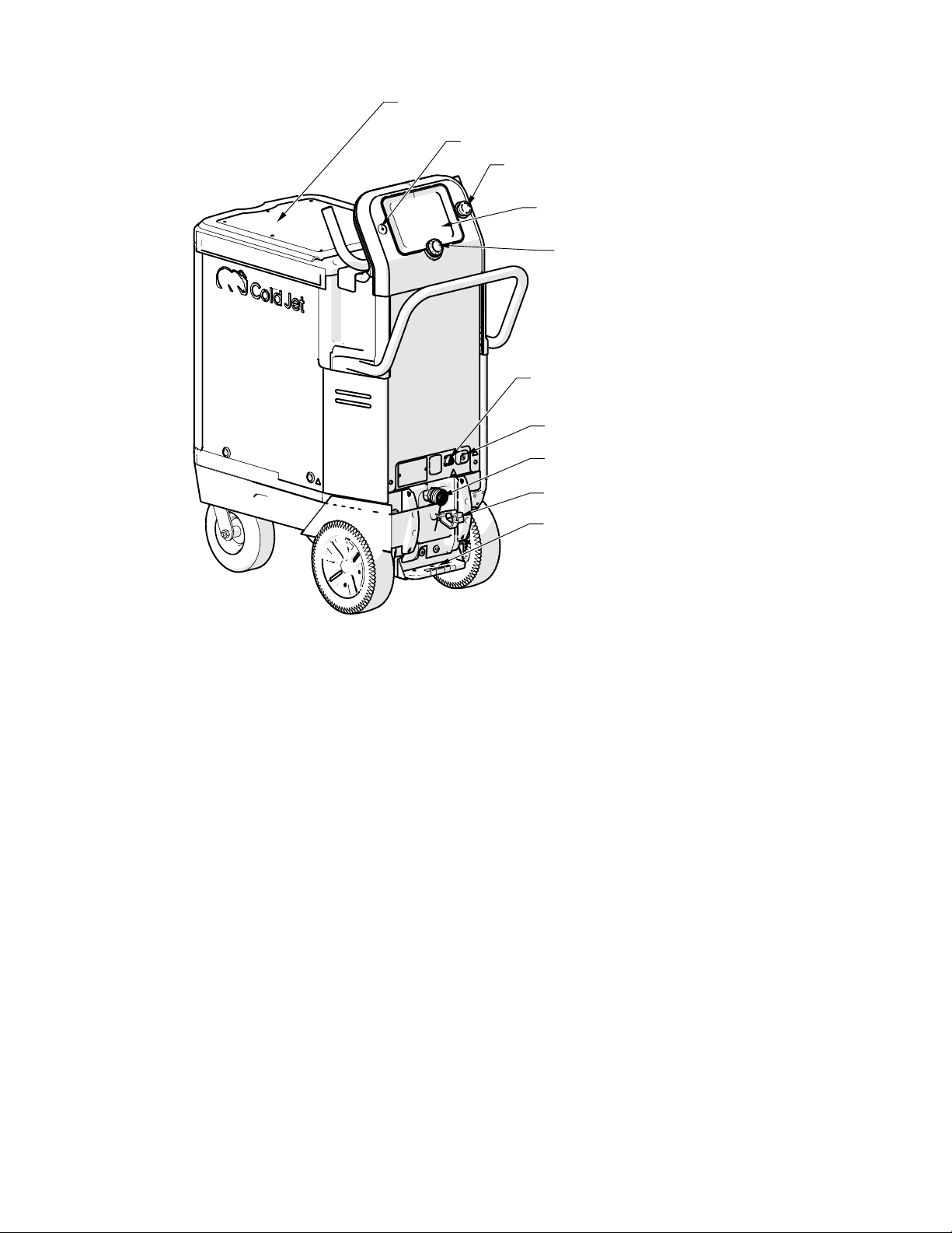
PLT 60 Components
Hopper Lid
Power Button
Emergency Stop
HMI Screen
Rotary Encoder Dial
Control Cable Connection
Power Supply Connection
Blast Hose Connection
Static Ground Reel
Parking Brake
9
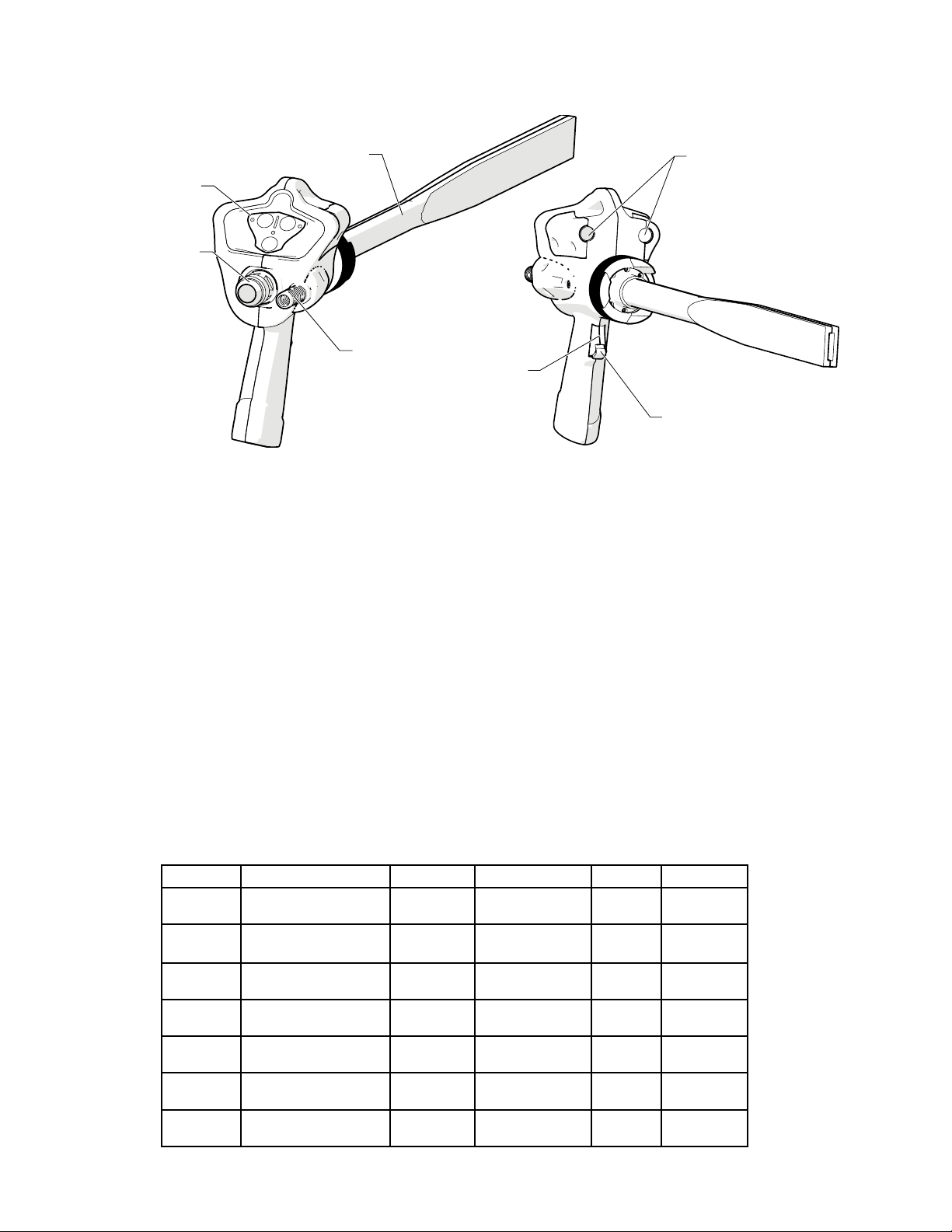
Performance Applicator Components
Nozzle
Applicator Controls
Blast Hose Connection
Applicator Control Cable
Lights
Trigger
Trigger Safety
Performance Applicator Nozzles
There are several dierent styles of nozzles, depending on the application the PLT 60 was ordered
for. The tables below can be used to help with initial settings as you set up the PLT 60 for operation.
Specialty nozzles are available on request.
Low and Standard Flow Nozzles
These straight nozzles have standard air consumption rate of 100 cfm or less at 80 psi.
Nozzle Air Consumption Blast Swath Dry Ice Feed rate Length Material
106S.6
110S.6
123S.7
310S.5
312S1
323S1
312S2
50cfm @ 80psi
1.4m3/min @ 5.5 bar
50cfm @ 80psi
1.4m3/min @ 5.5 bar
50cfm @ 80psi
3
1.4m
/min @ 5.5 bar
100cfm @ 80psi
2.8m3/min @ 5.5 bar
100cfm @ 80psi
3
/min @ 5.5 bar
2.8m
100cfm @ 80psi
2.8m3/min @ 5.5 bar
100cfm @ 80psi
2.8m3/min @ 5.5 bar
0.6 in
(1.5 cm)
0.6 in
(1.5 cm)
0.7 in
(1.8 cm)
0.45 in
(1.1 cm)
1 in
(2.5 cm)
1 in
(2.5 cm)
1.8 in
(4.6 cm)
1-3 lbs/min
0.5-1.4 kg/min
1-3 lbs/min
0.5-1.4 kg/min
1-3 lbs/min
0.5-1.4 kg/min
2-4 lbs/min
0.9-1.8 kg/min
2-4 lbs/min
0.9-1.8 kg/min
2-4 lbs/min
0.9-1.8 kg/min
2-4 lbs/min
0.9-1.8 kg/min
6 in
(15.2 cm)
10 in
(25.4 cm)
23 in
(58.4 cm)
10 in
(25.4 cm)
12 in
(30.5 cm)
23 in
(58.4 cm)
12 in
(30.5 cm)
Anodized
Aluminum
Anodized
Aluminum
Anodized
Aluminum
Aluminum
Aluminum
Aluminum
Aluminum
10

Specialty Nozzles
These nozzles have various congurations for special applications and operation.
Nozzle Air Consumption Blast Swath Dry Ice Feed rate Length Material
112HK
114P.5
307A135V.8
307A45H1
307A90H.8
307A90V1
308A45H.8
308A45V.8
309A45H.8
317A90H1
509C
70cfm @ 80psi
2.0m3/min @ 5.5 bar
70cfm @ 80psi
2.0m3/min @ 5.5 bar
100cfm @ 80psi
3
/min @ 5.5 bar
2.8m
100cfm @ 80psi
3
/min @ 5.5 bar
2.8m
100cfm @ 80psi
2.8m3/min @ 5.5 bar
100cfm @ 80psi
2.8m3/min @ 5.5 bar
100cfm @ 80psi
2.8m3/min @ 5.5 bar
100cfm @ 80psi
2.8m3/min @ 5.5 bar
120cfm @ 80psi
3
/min @ 5.5 bar
3.4m
100cfm @ 80psi
2.8m3/min @ 5.5 bar
150cfm @ 80psi
4.3m3/min @ 5.5 bar
0.25 in
(0.6 cm)
0.25 in
(0.6 cm)
0.75 in
(1.9 cm)
1 in
(2.5 cm)
0.75 in
(1.9 cm)
1 in
(2.5 cm)
0.75 in
(1.9 cm)
0.75 in
(1.9 cm)
0.75 in
(1.9 cm)
1 in
(2.5 cm)
N/A
1-3 lbs/min
0.5-1.4 kg/min
1-3 lbs/min
0.5-1.4 kg/min
2-4 lbs/min
0.9-1.8 kg/min
2-4 lbs/min
0.9-1.8 kg/min
2-4 lbs/min
0.9-1.8 kg/min
2-4 lbs/min
0.9-1.8 kg/min
2-4 lbs/min
0.9-1.8 kg/min
2-4 lbs/min
0.9-1.8 kg/min
3-5 lbs/min
1.4-2.3 kg/min
2-4 lbs/min
0.9-1.8 kg/min
3-5 lbs/min
1.4-2.3 kg/min
12 x 2 in
(30.5 x 5.1 cm)
10.3 in
(26.2 cm)
7.3 X 6.3 in
(18.6 x 16 cm)
7.3 x 5 in
(18.6 x 12.7 cm)
7 x 5.3 in
(17.8 x 13.5 cm)
7.3 x 7 in
186 x 178 mm
7.7 x 3.5 in
(19.6 x 8.9 cm)
7.7 x 3.5 in
(19.6 x 8.9 cm)
8.9 x 4 in
(22.6 x 10.2 cm)
16.6 x 3.4 in
(42.2 x 8.6 cm)
9 in
(22.9 cm)
Polymer
Coated SST
Polymer
Polymer
Coated SST
Polymer
Coated SST
Polymer
Coated SST
Polymer
Coated SST
Polymer
Coated SST
Polymer
Coated SST
Aluminum
Polymer
Coated SST
Multi
11
 Loading...