

ColdfusionX JLD-612, TET-612 Instruction Manual
Instructional Manuel
for
Rev c1.1 12-23-2011
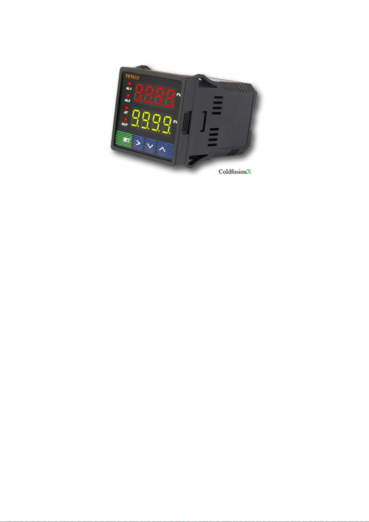
JLD-612/ TET-612 PID Temperature Controller
1. Product Highlight
Thermocouple supported: T, R, J, B, S, K, E, Wre3-Wre25.
Thermo Resistor supported: Pt100, Cu50.
Five ways outputs:
• Two Relay alarms output
• Two Relay output(J1), one PID relay output (J2, N.O.)
• Two Relay alarm output, and one PID SSR signal output (for an external SSR).
• Two Relay alarm output, and one PID SSR feedback output (for s SSR).
• Once Relay alarm output (J1), one Relay control (J2).
Time proportional PID controlled output to either a Relay output or the SSR control output.
Temperature can be set to display in either Fahrenheit or Celsius.
Manual control is capable
2. Specifications
Operating supply voltage: AC85-265V or DC85-360V.
Power consumption: =< 2 Watt.
Sampling speed: 4/sec.
SSR activated voltage: open circuit: 6V; short circuit: 40mA.
Accuracy: 0.2% of full scale.
LED Display: 0.28 inch; Red color.
Out of range indication: “EEEE”.
Ambient temperature requirement: 0~+50 Deg C.
Humidity requirement: =< 85% RH.
Relay Contact : AC220V / 3A.
Controller dimension: 48x48x82(mm).
Opening for installation: 45x45(mm).
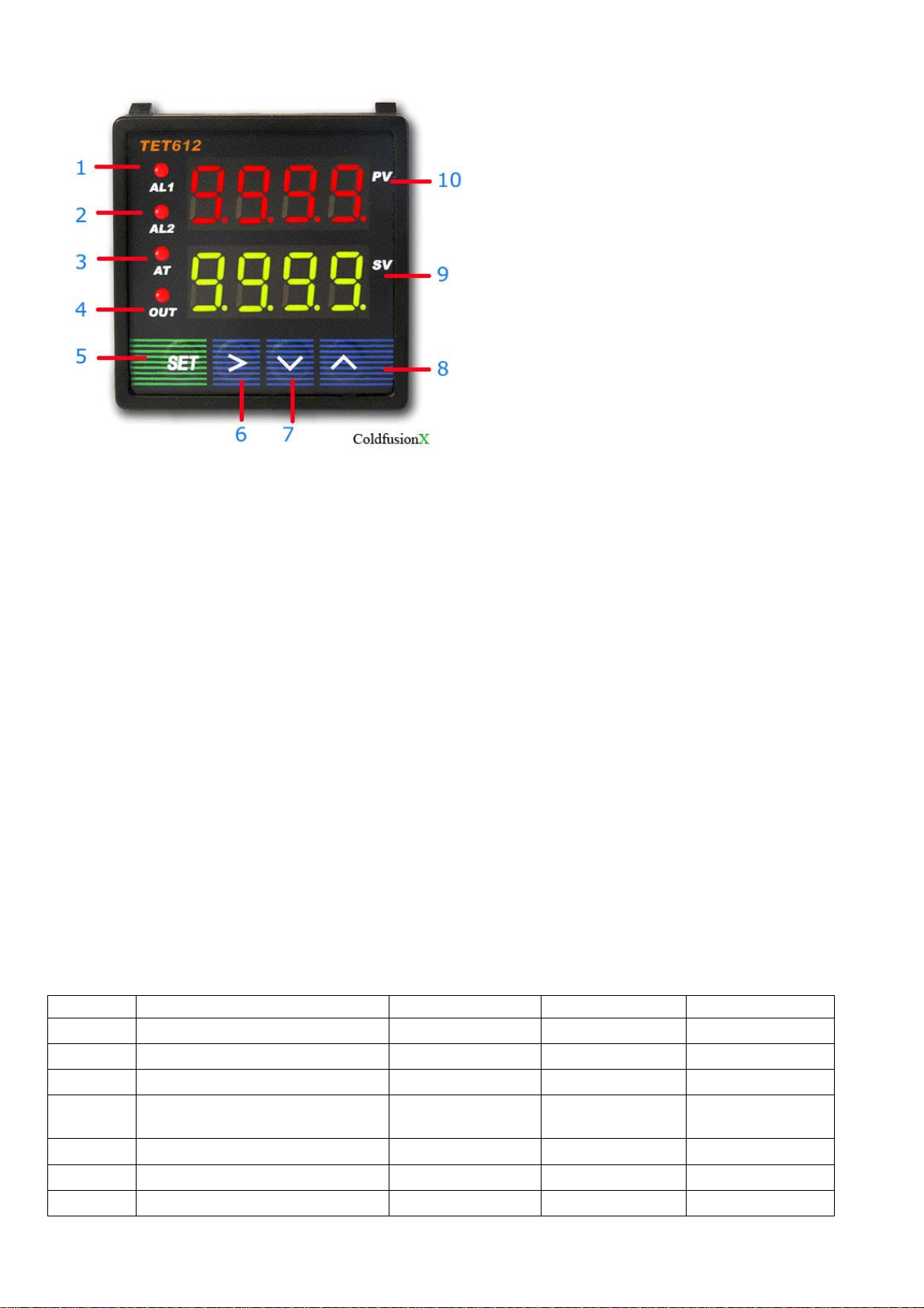
3. Panel Illustrations and Descriptions
Figure 1
1 -- AL1, relay J1 indicator.
2 -- AL2, relay J2 indicator.
3 -- AT, blanking during auto tuning process.
4 -- Out, output indicator.
5 -- Setting / Confirm.
6 -- Digit select / Auto tuning.
7 -- Select next parameter / value increment.
8 -- Selection previous parameter / value decrement.
9 -- Target value.
10-- Current value.
4. Parameter Setting
i Press (SET) to enter setting mode, enter ”0089”, then press (SET) again.
ii Press (v) and/or (^) and then (SET) to select parameters.
iii Press (SET) to confirm entry or to select
iv Press (^) to until “End” appear in red display to exit parameter setting loop.
a) Initialization parameter setting loop.
Table 1. Initialization Parameters:
Symbol Description Range Default Comment
Inty
Outy
Hy
PSb
Rd
CorF
End
Method of controlled output 0,1,2,3,4 2 Note 1
Temp. sensor See table 2 Pt10.0
Step-Type Feedback 0-9999 0.3
Temp sensor error
correction coefficient
Heating=0;Cooling=1 0,1 0
Celsius=0;Fahrenheit=1 0,1 0
Exit
-1000~1000
deg C
0

<-
Pt100
Table 2. Temperature Sensor Type:
Symbol Description Range Comment
T
R
J
WRe
B
S
K
E
P10.0
P100
Cu50
Note: if a wrong probe is using, it may cause “EEE.E” error. Default is “K”
Probe Connection:
For J, K or any two wires probe, connection terminals are #9, #10
For Pt-100 probe (3 wires), the red wire is connected to #8, and the two blues are connected to
#9, #10
Output setting ‘OutY’
T Thermocouple -200 ~ 4000 Internal Resistant 100k
R Thermocouple -50 ~ 1600 Internal Resistant 100k
J Thermocouple -200 ~ 1200 Internal Resistant 100k
WRe Thermocouple 0 ~ 2300 Internal Resistant 100k
B Thermocouple 350 ~ 1800 Internal Resistant 100k
S Thermocouple -50 ~ 1600 Internal Resistant 100k
K Thermocouple -200 ~ 1300 C
-328 ~ 2372 F
E Thermocouple -200 ~ 900 Internal Resistant 100k
P10.0 Thermo
Resistor
Pt100 Thermo
Resistor
Cu50 Thermo
Resistor
-200.0 ~ 600.0 Constant Output 0.2mA
-200 ~ 600 Constant Output 0.2mA
-50.0 ~ 150.0 Constant Output 0.2mA
Internal Resistant 100k
0: Relay J1 and J2 as Alarm outputs; SSR and SV Disabled, it is normally used for upper/lower
1: Relay J1 alarm output; Relay J2 PID output controlled by SV. AH2, AL2 values are not used;
2: Relay J1 and J2 as alarm outputs; SSR PID output 8V SSR signal. Target: SV
3. J1, J2 alarm output; differential control by SSR. See Fig 3
4. J1 alarm, differential control on J2, SSR disabled, AH2, AL2 disabled. See Fig 3
Fig. 2
limits alarm trigger control. See Fig 2
SSR control output disabled. See Fig 2
 Loading...