

Instructional Manuel
for
Rev c1.1 12-23-2011
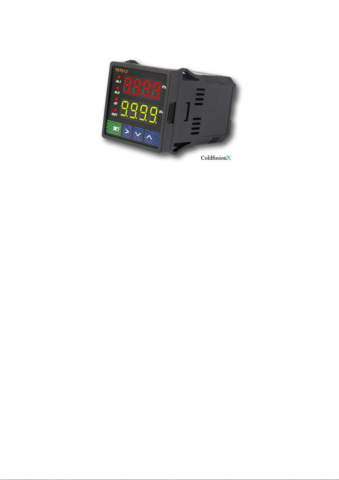
JLD-612/ TET-612 PID Temperature Controller
1. Product Highlight
Thermocouple supported: T, R, J, B, S, K, E, Wre3-Wre25.
Thermo Resistor supported: Pt100, Cu50.
Five ways outputs:
• Two Relay alarms output
• Two Relay output(J1), one PID relay output (J2, N.O.)
• Two Relay alarm output, and one PID SSR signal output (for an external SSR).
• Two Relay alarm output, and one PID SSR feedback output (for s SSR).
• Once Relay alarm output (J1), one Relay control (J2).
Time proportional PID controlled output to either a Relay output or the SSR control output.
Temperature can be set to display in either Fahrenheit or Celsius.
Manual control is capable
2. Specifications
Operating supply voltage: AC85-265V or DC85-360V.
Power consumption: =< 2 Watt.
Sampling speed: 4/sec.
SSR activated voltage: open circuit: 6V; short circuit: 40mA.
Accuracy: 0.2% of full scale.
LED Display: 0.28 inch; Red color.
Out of range indication: “EEEE”.
Ambient temperature requirement: 0~+50 Deg C.
Humidity requirement: =< 85% RH.
Relay Contact : AC220V / 3A.
Controller dimension: 48x48x82(mm).
Opening for installation: 45x45(mm).
3. Panel Illustrations and Descriptions
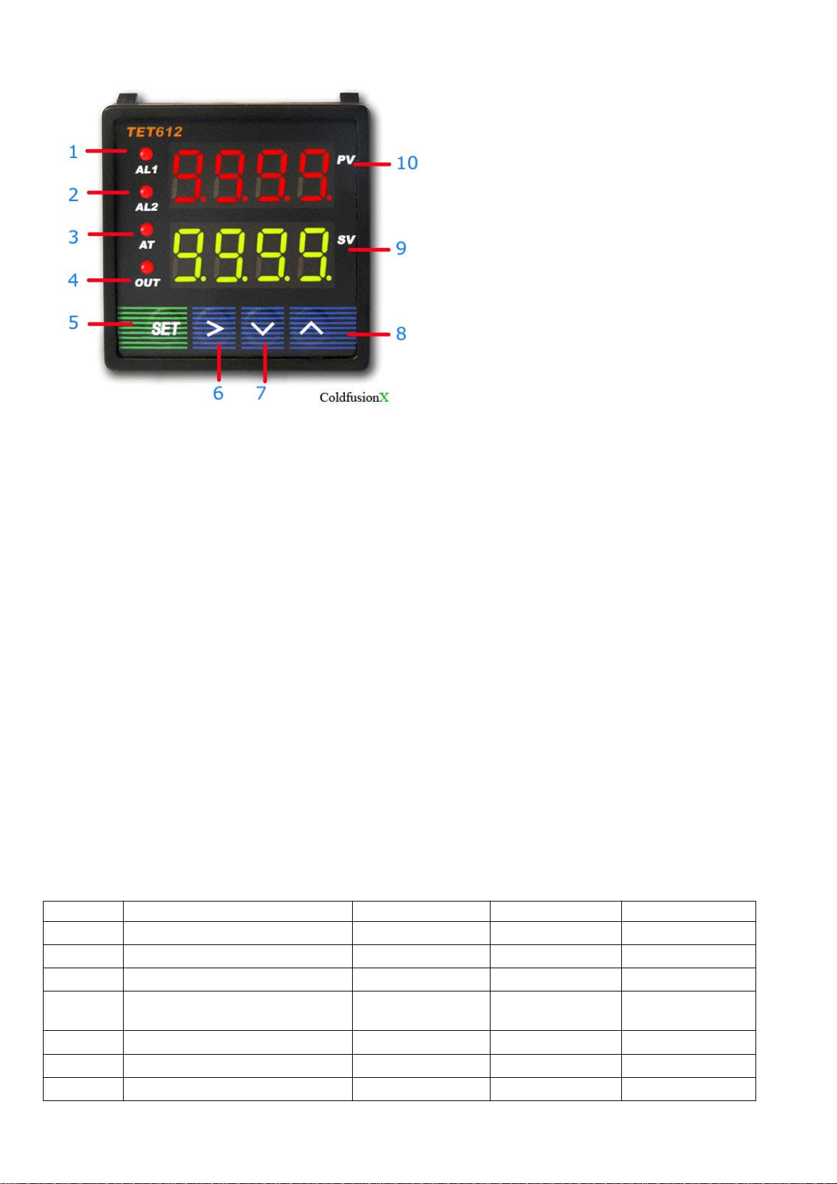
Figure 1
1 -- AL1, relay J1 indicator.
2 -- AL2, relay J2 indicator.
3 -- AT, blanking during auto tuning process.
4 -- Out, output indicator.
5 -- Setting / Confirm.
6 -- Digit select / Auto tuning.
7 -- Select next parameter / value increment.
8 -- Selection previous parameter / value decrement.
9 -- Target value.
10-- Current value.
4. Parameter Setting
i Press (SET) to enter setting mode, enter ”0089”, then press (SET) again.
ii Press (v) and/or (^) and then (SET) to select parameters.
iii Press (SET) to confirm entry or to select
iv Press (^) to until “End” appear in red display to exit parameter setting loop.
a) Initialization parameter setting loop.
Table 1. Initialization Parameters:
Symbol Description Range Default Comment
Inty
Outy
Hy
PSb
Rd
CorF
End
Method of controlled output 0,1,2,3,4 2 Note 1
Temp. sensor See table 2 Pt10.0
Step-Type Feedback 0-9999 0.3
Temp sensor error
correction coefficient
Heating=0;Cooling=1 0,1 0
Celsius=0;Fahrenheit=1 0,1 0
Exit
-1000~1000
deg C
0

<-
Pt100
Table 2. Temperature Sensor Type:
Symbol Description Range Comment
T
R
J
WRe
B
S
K
E
P10.0
P100
Cu50
Note: if a wrong probe is using, it may cause “EEE.E” error. Default is “K”
Probe Connection:
For J, K or any two wires probe, connection terminals are #9, #10
For Pt-100 probe (3 wires), the red wire is connected to #8, and the two blues are connected to
#9, #10
Output setting ‘OutY’
T Thermocouple -200 ~ 4000 Internal Resistant 100k
R Thermocouple -50 ~ 1600 Internal Resistant 100k
J Thermocouple -200 ~ 1200 Internal Resistant 100k
WRe Thermocouple 0 ~ 2300 Internal Resistant 100k
B Thermocouple 350 ~ 1800 Internal Resistant 100k
S Thermocouple -50 ~ 1600 Internal Resistant 100k
K Thermocouple -200 ~ 1300 C
-328 ~ 2372 F
E Thermocouple -200 ~ 900 Internal Resistant 100k
P10.0 Thermo
Resistor
Pt100 Thermo
Resistor
Cu50 Thermo
Resistor
-200.0 ~ 600.0 Constant Output 0.2mA
-200 ~ 600 Constant Output 0.2mA
-50.0 ~ 150.0 Constant Output 0.2mA
Internal Resistant 100k
0: Relay J1 and J2 as Alarm outputs; SSR and SV Disabled, it is normally used for upper/lower
1: Relay J1 alarm output; Relay J2 PID output controlled by SV. AH2, AL2 values are not used;
2: Relay J1 and J2 as alarm outputs; SSR PID output 8V SSR signal. Target: SV
3. J1, J2 alarm output; differential control by SSR. See Fig 3
4. J1 alarm, differential control on J2, SSR disabled, AH2, AL2 disabled. See Fig 3
Fig. 2
limits alarm trigger control. See Fig 2
SSR control output disabled. See Fig 2

Fig. 3
Ini
ll
Rd=0 (heating) Rd=1 (cooling)
To initial:
PV ≤ (SV – HY) PV ≥(SV + HY)
Relay latched or SSR On Relay latched or SSR On
To stop:
PV ≥ SV PV ≤ SV
Relay unlatched or SSR off Relay unlatched or SSR off
Note: HY = AH - AL
tia
Op e r a t i n g Mode
zation parameter setting
Par amet er Di spl ay
Ent er Code
0089
inty
Outy
Atud
psb
Heat i ng / Cool i ng Selection
rd
corf
XXXX
X
X
XXXX
X
X
end
Figure 4.

b) To enter PID parameter setting mode press (SET), then enter code “0036”, press (SET) again.
Table 3. PID and Relevant Parameters:
Symbol Description Range Default Comment
P
I
D
SouF
Ot
Filt
End
P,I and d parameters control the accuracy and respond time of the temperature controller. Autotuning is recommended for user who does not familiar PID control theory. P, I and d values
should only be adjusted by professionals.
Note 4
Proportional Band (P): When P increases, fluctuation of object being controlled decreases. When
P decreases, fluctuation of object being controlled increases. When P value is too small, system
may become non-converge.
Note 5
Integration time (I): its purpose is to reduce static error. When I decrease, respond speed is
faster but system is less stable. When I increase, respond speed is slower, but system is more
stable.
Note 6
Differentiation time (d): its purpose is to control in advance and compensate delay. Setting dvalue too small or too large would decrease system stability, oscillation or even non-converge.
Note 7
Proportional Band 0.1 ~ 99.9 (%) 5.0 Note 4
Integration Time 2 ~ 1999 (Sec) 100 Note 5
Differentiation Time 0 ~ 399 (Sec) 20 Note 6
Overshoot Suppression
Coefficient
Control Period 2 ~ 199 (Sec) 2 Note 8
Digital Filtering Strength 0 ~ 3 0 Note 9
Exit
0.0 ~ 1.0 0.2 Note 7
Overshoot suppression coefficient. When overshoot exists, increase SouF. When undershoot
exists, decrease SouF.
Note 8
Control Period (ot): When ot gets smaller, heating/cooling cycle is drived faster, system respond
speed is faster. But when using contact control (Relays), contacts wear out faster.
When contact control (Relay) is used, normally set ot=5~15.
When non-contact control (SSR) is used, normally set ot=2.

Note 9
Digital Filtering (Filt): Filt=0, filter disabled; Filt=1, weak filtering effect; Filt=3, strongest
filtering effect; Stronger the filtering, more stable the readout, but has more readout display delay.
C) To enter temperature and alarm parameter setting mode press (SET), then enter code “0001”,
press (SET) again.
Table 4. Temperature Setting and Alarm Related Parameters:
Symbol Description Range Default Comment
SV
AH1
AL1
AH2
AL2
End
5. Auto-Tuning
By simply press a single button the built-in artificial intelligent is activated to automatically
Target
Temperature (SV)
Relay Closed With testing
Relay Opened With testing
Relay Closed With testing
Relay Opened With testing
Exit
With testing
range
range
range
range
range
80.0
80.0
90.0
80.0
90.0
calculate and set parameters (P, I, D, SouF, ot) that fit the condition to be controlled.
SV
Measuri ng
Cur v e
Figure 6.
a) How to Start and stop auto-tuning process:
i. To activate auto-tuning, press and hold (>) until “AT” indicator blinks, which indicates autotuning is in progress. When auto-tuning finish, “AT” indicator is off. Now newly calculated PID
parameters are remembered and start to be used.
a) ii. To EXIT during auto-tuning process, press and hold (>) until “AT” indicator turns off. Then
previous PID parameters values are resumed. . Note, in order to have auto-tuning to work
properly, a closed-loop system must be established; that is a SSR, heater, thermocouple are
all connected. It may take an hour or up to 24hrs to complete the Auto-tuning. The amount of
time it take is totally depends on how complicated the environment that the controller being
installed.
ON OFF ON
OFF

Pt100 - Red lead terminal 8
Blue leads to terminals 9 and 10
6. Connection Terminals (back view).
Polarity of power at terminal 1 and 2 do not matter. The “R” is not an external resistor; it is only
available from the Pt-100 thermistor.
Relay J1: #3, #4 = normally closed, #4, #5 = normally open
Relay J2: #13, #14 = normally open
Note: terminal #11 is an opened slot and
there is a diode installed for ambient
temperature referencing. It’s not a missing
screw or defective. For DC type controller,
the power is 12V ~ 32V. The ‘R’ is not a
resistor but it is a feedback resistance from
the PT-100 probe. Do not reverse + / -
when installing a thermocouple. If so, the
increment and decrement reading will be
opposite. For PT100 probe, red wire goes
to #8 while two blues wires go to #9,#10
SSR Control
Fig 7
Caution: a heat-sink is required for the SSR
Relay J1 Control

Relay
Note: Vref can be AC or DC. It depends on the type of the relay it power
7. Device Application Example
a) User wants to control temperature (T) of a furnace, and 0 ~ 1000 deg Celsius sensor range is
required. Furnace is wanted to be maintained at 800 deg C. Alarm1 will go off if T>850 deg C,
and Alarm2 will go off if T<750 deg C. System power supply is AC110V. Installation opening is
45x45(mm). SSR will be used to control the heating element.
b) Choose JLD612 with a K-type thermocouple.
c) See figure for connection diagram.
d) Parameter setting:
(Inty)=
K; (SV)=800 deg C;
(outy)=2; (AH1)=850 deg C;
(Hy)=0.3; (AL1)=848 deg C;
(psd)=0; (AH2)=750 deg C;
(rd)=0; (AL2)=752 deg C;
(CorF)=0;
(auto-tuning is used to set PID parameters)
e) Power up the controller. Keep pressing (>) to activate auto-tuning. When “AT” stop blinking,
new PID parameters are generated and recorded for the system. The controller back to
normal operation mode and the furnace temperature will stay at 800 deg ‘C.
Presents by Lightobject.com. All Rights Reserved.
 Loading...