

Page 1
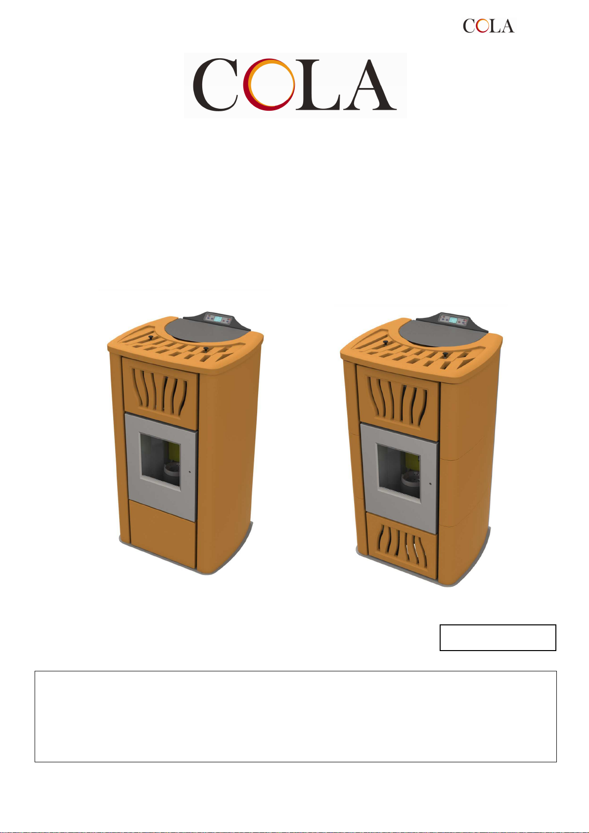
Manuale d’installazione, uso e manutenzione
Installation, use and maintenance manual
Manuel d’installation, d'utilisation et d'entretien
Installations-, Bedienungs- und Wartungsanleitung
Stufa a pellet mod - Pellet stove model - Poêle à granulés mod. - Pelletofen Modell
TERMO-POWER - TERMO POWER LUX
484215150-M4_03/12
Hardware - M
Leggere attentamente le istruzioni prima dell’installazione, utilizzo e manutenzione.
Il manuale è parte integrante dell’apparecchio.
Read the instructions carefully before installation, use and maintenance.
The manual is an integral part of the unit.
Lire attentivement les instructions avant d'installer, d'utiliser et d'entretenir le poêle.
Le manuel fait partie intégrante de l'appareil.
Vor Installation, Gebrauch und Wartung muss diese Anleitung aufmerksam durchgelesen werden.
Das Handbuch ist wesentlicher Bestandteil des Geräts.
TERMO-POWER
1
Page 2

IT
............................................................................................................................................
La Ditta COLA garantisce i propri prodotti secondo le norme attualmente in vigore , ad esclusione delle parti
soggette a normale usura . Per le condizioni di garanzia rivolgersi all’importatore o al rappresentante autorizzato, il
quale può integrare il periodo della garanzia obbligatoria con un periodo supplementare a sua totale ed esclusiva
responsabilità. La garanzia del prodotto decade per qualsiasi inconveniente, rottura o incidente dovuto al mancato
rispetto o applicazione delle indicazioni contenute nel presente manuale
GB
.......................................................................................................................................
COLA guarantees its products, except for parts subject to normal wear, in accordance with the current regulations.
For the warranty terms, please contact the importer or the authorised agent who can integrate the compulsory
warranty period with an additional period under his sole and exclusive responsibility.
The product warranty is invalidated for any trouble, breakage or accident due to failure to comply with or apply the
instructions provided in this manual.
FR
.......................................................................................................................................
La société COLA garantit ses produits selon les normes actuellement en vigueur, à l'exception des parties qui sont
soumises à une usure normale. Pour les conditions de garantie, s’adresser à l’importateur ou au représentant
autorisé qui pourra accorder une extension de la durée contractuelle constructeur sous sa propre responsabilité. La
garantie déchoit automatiquement et de plein droit pour tous les dommages, ruptures ou incidents causés par
l’inobservation ou l'inapplication des instructions contenues le présent manuel.
DE
.....................................................................................................................................
Die Firma COLA garantiert ihre Produkte gemäß den derzeit geltenden Bestimmungen mit Ausnahme der
Verschleißteile.
Für die Garantiebedingungen wenden Sie sich bitte an den Importeur oder an den autorisierten Vertreter, der die
obligatorische Garantielaufzeit auf ausschließlich eigene Verantwortung verlängern kann.
Die Garantie des Produkts erlischt im Fall von Störungen, eines Defekten oder Unfällen, die auf die Missachtung der
in dieser Anleitung enthaltenen Anleitungen zurückzuführen sind.
3-40
41-77
79-115
116-152
TERMO-POWER
2
Page 3

1. AVVERTENZE GENERALI
1.1. Introduzione
1.2. Come utilizzare il manuale
1.3. Norme di sicurezza
1.4. Descrizione tecnica
1.5. Combustibile e uso consentito
1.6. Accessori in dotazione
1.7. Riferimenti normativi
1.8. Targa di identificazione
1.9. Messa fuori servizio della stufa
1.10. Istruzioni per richiesta di intervento e
ricambi
2. TRASPORTO ED INSTALLAZIONE
2.1. Imballo, movimentazione, spedizione e
trasporto
2.2. Luogo d’installazione, posizionamento e
sicurezza antincendio
2.3. Presa aria
2.4. Scarico fumi di combustione
2.4.1. Tipologie di installazione
2.5. Controllo posizione bracere e turbolatori
2.6. Collegamento elettrico
2.7. Schema elettrico
2.8. Schema elettrico per impianto a zone
2.9. Collegamenti idraulici
2.10. Pronto intervento
3. SICUREZZE DELLA STUFA
3.1. Distanza sicurezza mat. infiammabili.
3.2. Sicurezza scarico fumi
3.3. Sicurezza sovrapressione in camera di
combustione
3.4. Surriscaldamento – termostato sicurezza
temperatura serbatoio pellet
3.5. Sicurezza contro il ritorno di fiamma sul
canale alimentazione pellet
3.6. Dispositivo elettrico di protezione della
sovracorrente
3.7. Sicurezza da interruzione di alim.elettrica
3.8. Sicurezza sovrapressione circuito idr.
3.9. Guasto ventilatore fumi
4. USO DELLA STUFA
4.1. Premessa
4.2. Descrizione del pannello comandi
4.3. Accensione
4.3.1 Controllo prima dell’accensione
4.3.2 Fase di avvio
4.4. Fase di lavoro
4.4.1 Modifica impostazione temperatura
ambiente
4.4.2 Modifica impostazione temperatura
acqua
4.4.3 Riavvio da STAND-BY
4.4.4 Pulizia del braciere
4.4.5 Acqua calda sanitaria con scambiatore
rapido
4.4.6 Acqua calda sanitaria con bollitore ad
accumulo
4.4.7 Impianto con puffer / accumulatore di
calore
4.6 Menù
4.6.1 menù 01 – regola ventole
4.6.2 menù 02 – set orologio
4.6.3 menù 03 – abilita crono
4.6.4 menù 04 – scegli lingua
4.6.5 menù 05 – modo stand-by
4.6.6 menù 06 – cicalino
4.6.7 menù 07 – carico iniziale
4.6.8 menù 08 – stato stufa
4.6.9 menù 09 – tarature tecnico
4.7 Telecomando
4.7.1 sostituzione batteria
4.8 Termostato – cronotermostato esterno
4.9 Periodo di inattività (fine stagione)
5. PULIZIA DELLA STUFA
5.1 Pulizia braciere
5.2 Pulizia contenitore cenere
5.3 Pulizia del vetro
5.4 Pulizia estrattore fumi e camera di
combustione
5.5 Pulizia debimetro
5.6 Pulizia delle ceramiche (modelli in
ceramica)
5.7 Pulizia raccordo fumi – canna fumaria
5.8 Pulizia scambiatori con il dispositivo
scuoti-turbolatori
6. MANUTENZIONE
6.1 Premessa
6.2 Smontaggio rivestimento T-POWER
6.3 Smontaggio rivestimento T-POWER LUX
6.4 Componenti interni della stufa
6.5 Componenti elettrici
6.6 Componenti idraulici
7. RICERCA GUASTI
7.1 Gestione degli allarmi
8. ALLEGATI
8.1 Informazioni marcatura CE
TERMO-POWER
3
Page 4
1 AVVERTENZE GENERALI
1.1 Introduzione
Gentile Cliente ,
Desideriamo innanzi tutto ringraziarLa per la fiducia accordataci acquistando un nostro prodotto. La invitiamo a
leggere e seguire attentamente i consigli contenuti in questo manuale d’installazione, uso e manutenzione al fine di
poter sfruttare al meglio le qualità del prodotto.
1.2 Come utilizzare il manuale
La ditta produttrice si riserva di apportare in qualsiasi momento, senza preavviso alcuno, eventuali modifiche
tecniche od estetiche ai prodotti.
Le operazioni d’installazione , uso e manutenzione della stufa devono soddisfare i requisiti descritti in questo
manuale nonchè le leggi e le norme Europee , Nazionali , Regionali , Provinciali e Comunali .
I disegni, le misure, gli schemi ed ogni altra configurazione, sono qui riportati solo a scopo esemplificativo.
Il presente manuale costituisce parte integrante del prodotto ; verificare che sia sempre a corredo dell’apparecchio e
in caso di vendita , trasferimento ad un altro proprietario o installato in un altro luogo assicurarsi della sua presenza
in modo che possa essere consultato in qualsiasi momento .
In caso di smarrimento o danneggiamento richiedere copia al Centro di Assistenza Tecnico autorizzato in modo che
l’apparecchio abbia sempre a corredo il proprio manuale .
Questo simbolo indica la presenza di un messaggio importante a cui prestare particolare attenzione in
quanto la mancata osservanza di quanto scritto, può provocare seri danni alla stufa e alle persone
1.3 Norme di sicurezza.
- Leggere il manuale d’uso e manutenzione prima di installare , accedere e manutentore la stufa .
- Eseguire installazione,collegamento elettrico,collaudo e manutenzione da un tecnico qualificato e/o autorizzato.
- Collegare la stufa ad una canna fumaria a Norma tramite un terminale ispezionabile ; Il collegamento di più
apparecchi può avvenire solo se viene contemplato dalle Norme locali e concesso dall’Organismo di controllo della
canna fumaria.
- Collegare la stufa all’aspirazione tramite un tubo o presa d’aria dall’esterno .
- Collegare la stufa ad una presa elettrica a Norma tensione 230 V- 50 Hz .
-
Nel modello TERMO collegare l’apparecchio all’impianto di riscaldamento ; esso non può in nessun
caso essere usato senza l’allacciamento idraulico e senza la carica dell’acqua interna alla termocamera .
- Verificare che l’impianto elettrico e le prese abbiano la capacità di sopportare l’assorbimento massimo
dell’apparecchio riportata sull’etichetta e sul presente manuale.
- Prima di ogni manutenzione staccare la spina elettrica dalla stufa ed operare solo con stufa fredda.
- Non impiegare liquidi o sostanze infiammabili per accendere la stufa o per ravvivare la fiamma: a stufa
accesa l’accensione del pellet è automatica.
- La stufa a pellet deve essere alimentata solo ed esclusivamente con pellet di legna aventi le
caratteristiche descritte nel presente manuale.
- La stufa non deve essere usato come inceneritore .
- Non chiudere in alcun caso le aperture di ingresso dell’aria comburente e uscita fumi .
- E’ vietato manipolare sostanze facilmente infiammabili o esplosive nelle vicinanze della stufa durante
il suo funzionamento.
- Non rimuovere la griglia di protezione del serbatoio pellet.
- E’ vietato il funzionamento della stufa con la porta fuoco aperta e/o vetro rovinato o rotto.
- Durante il funzionamento il forte calore sviluppato dalla combustione del pellet surriscalda le superfici esterne
della stufa in particolare porta fuoco, maniglia e tubo scarico fumi .Evitare quindi di entrare in contatto con tali
parti senza opportune protezioni .
- Tenere ad opportuna distanza di sicurezza oggetti non resistenti al calore e/o infiammabili .
- Pulire regolarmente il braciere ad ogni accensione o ricarica pellet .
- Evitare la formazione di fumo ed incombusti in fase di accensione e/o durante il normale funzionamento,
l’eccessivo accumulo di pellet incombusto nel braciere deve essere rimosso manualmente prima di procedere
con una nuova accensione .
- Pulire regolarmente il condotto e deflettori fumi all’interno della camera di combustione da personale qualificato .
- Avvertire bambini e ospiti dei pericoli sopra descritti .
-
In caso di anomalie di funzionamento, la stufa può essere riaccesa solo dopo avere ripristinato la
causa del problema .
- Qualsiasi manomissione e/o sostituzione non autorizzata di particolari non originali della stufa può causare
pericolo per l’incolumità dell’utente e solleva il costruttore da ogni responsabilità civile e penale.
- Utilizzare solo ricambi originali consigliati dal produttore .
Una voce che richiede particolare attenzione è evidenziata in con il “testo in grassetto”
La ditta produttrice non è responsabile di inconvenienti, rotture o incidenti dovuti al mancato rispetto o
alla mancata applicazione delle indicazioni soprascritte e contenute nel manuale .
TERMO-POWER
4
Page 5

1.4 Descrizione tecnica
La stufa funziona esclusivamente a pellet e permette una facile installazione con l’impianto di riscaldamento . I
sistemi di controllo automatici di cui è dotata garantiscono una resa termica ottimale ed una completa combustione,
inoltre sono presenti dei sistemi di sicurezza atti a garantire un funzionamento sicuro sia per i componenti della stufa
sia per l’utente .
L’apparecchio installato a norma funziona con qualsiasi condizione climatica esterna e comunque in condizioni
critiche (vento forte , gelo , ect.) possono intervenire i sistemi di sicurezza che spengono la stufa .
Struttura
Camera di combustione
Potenza termica nominale - ridotta
Pot. termica produzione H2O P nom.- P rid
Pot. termica resa al riscaldamento aria P nom – P rid
Consumo orario P nom.- P rid
Rendimento P nom.- P rid
Temperatura uscita fumi P nom.- P rid
Emissioni CO al 13% O2
Flusso gas di scarico
Emissioni polveri al 13% O2
Tiraggio minimo
Tubo uscita fumi
Tubo presa d’aria
acciaio e ghisa
acciaio
P.nom 23.5 kW P rid. 7.1 kW
P.nom 20.1 kW P rid. 5.6 kW
P.nom 3.4 kW P rid 1.44 kW
P.nom. 5.1 kg./h* P.
rid
.1.52 kg./h.*
P.nom. 93.6 % P.rid. 95.2 %
P.nom. 119.3 °C P.rid. 58.9 °C
P.nom. 0.005 % P.rid. 0.01 %
P.nom. 13.9 g/s P.rid. 7.6 g/s
P.nom. 10.7 mg/m3
10 Pa
Ø 100 mm
Ø 50 mm
Alimentazione elettrica
Assorbimento elettrico
Distanza minima di sicurezza dietro,lato dx lato sx
pavimento
Capacità vaso d’espansione
Capacità termocamera
Pressione max di esercizio
Dimensioni (mm)
Peso della stufa
Capacità serbatoio
Volume max riscaldabile
230 V - 50 Hz
420 W max in fase di accensione
140 W per il normale funzionamento
200 – 200 – 0 mm
8 litri
Litri 23
2 bar
H x L x P = 1241 x 700 x 627 mm
212 kg - T-POWER
254 kg - T-POWER LUX
48 kg
530 m3 **
* Il consumo di pellet può variare dal tipo di pellet utilizzato .
** Considerando 35 W/h per m3. Il fabbisogno energetico dell’edificio può variare in funzione
dell’isolamento , della tipologia e della zona climatica .
TERMO-POWER
5
Page 6
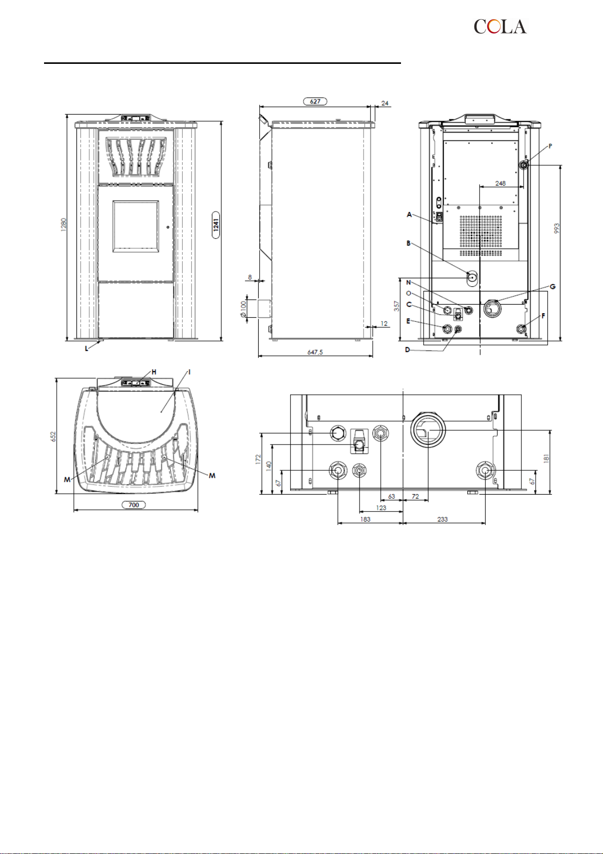
Ingombri termo-stufa pellet TERMO-POWER – TERMO-POWER LUX
Legenda:
A - Allacciamento cavo elettrico
B - Aspirazione aria comburente
C - Scarico acqua in sovrappressione ( 1/2" femm - 3 bar )
D - Allacciamento acquedotto
E - Ritorno impianto ( 1" maschio )
F - Mandata impianto ( 1" maschio )
G - Allacciamento tubo espulsione fumi D 100 mm
H - Pannello comandi mod.F047
I - Sportello serbatoio pellet
L - Piedini regolabili
M - Pomello scuoti turbolatori
N - Mandata sanitario opzionale ( 3/4" M – POMPA _ ½” M – SCAMBIATORE)
O - Ritorno sanitario opzionale ( 3/4" M – POMPA _ ½” M – SCAMBIATORE)
P - Attacco supplementare mandata senza pompa ( 1" maschio )
Ingombri stufa Termo-POWER
TERMO-POWER
6
Page 7
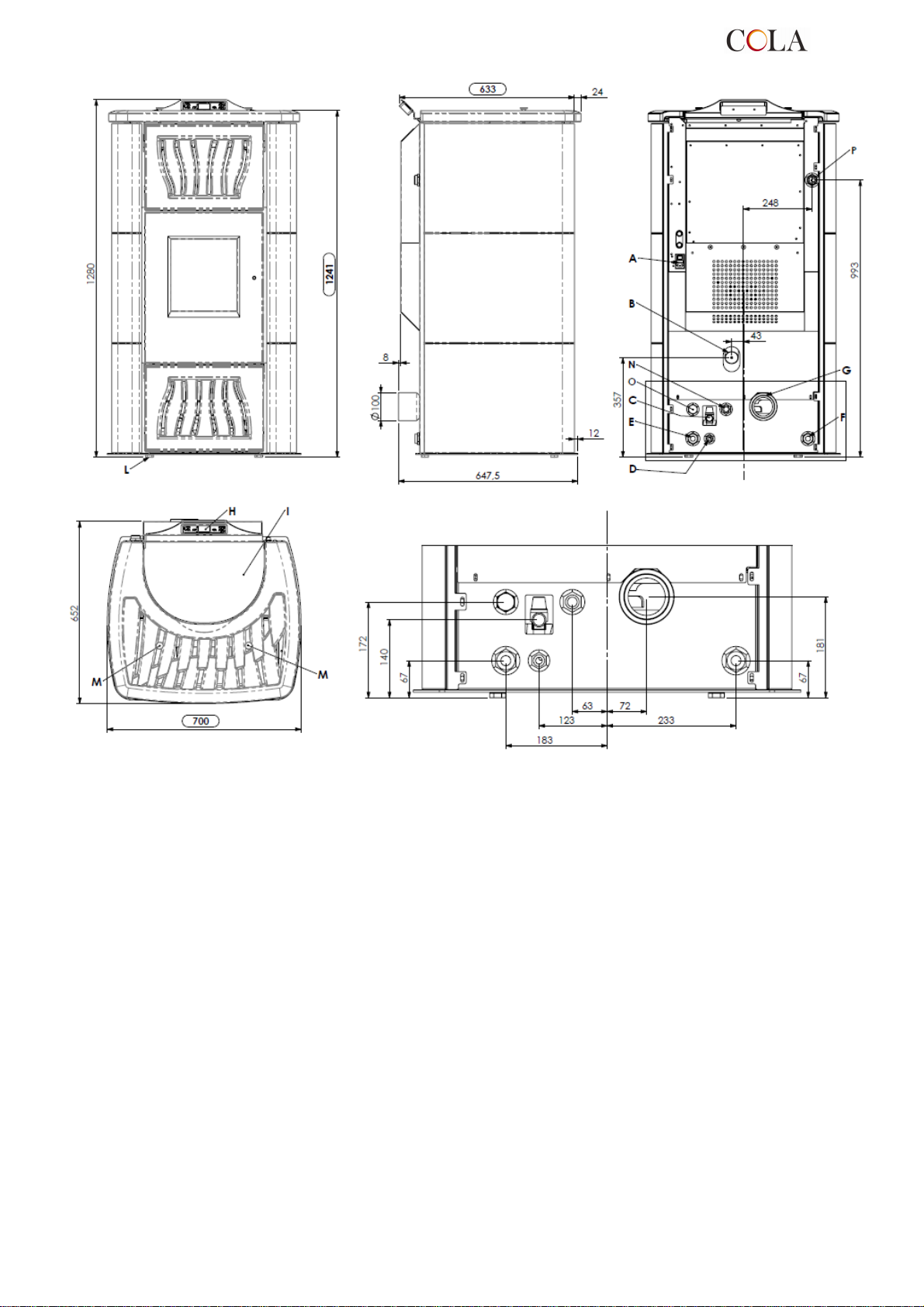
Legenda:
A - Allacciamento cavo elettrico
B - Aspirazione aria comburente
C - Scarico acqua in sovrappressione ( 1/2" femm - 3 bar )
D - Allacciamento acquedotto
E - Ritorno impianto ( 1" maschio )
F - Mandata impianto ( 1" maschio )
G - Allacciamento tubo espulsione fumi D 100 mm
H - Pannello comandi mod.F047
I - Sportello serbatoio pellet
L - Piedini regolabili
M - Pomello scuoti turbolatori
N - Mandata sanitario opzionale ( 3/4" M – POMPA _ ½” M – SCAMBIATORE)
O - Ritorno sanitario opzionale ( 3/4" M – POMPA _ ½” M – SCAMBIATORE)
P - Attacco supplementare mandata senza pompa ( 1" maschio )
Ingombri stufa Termo-POWER LUX
TERMO-POWER
7
Page 8
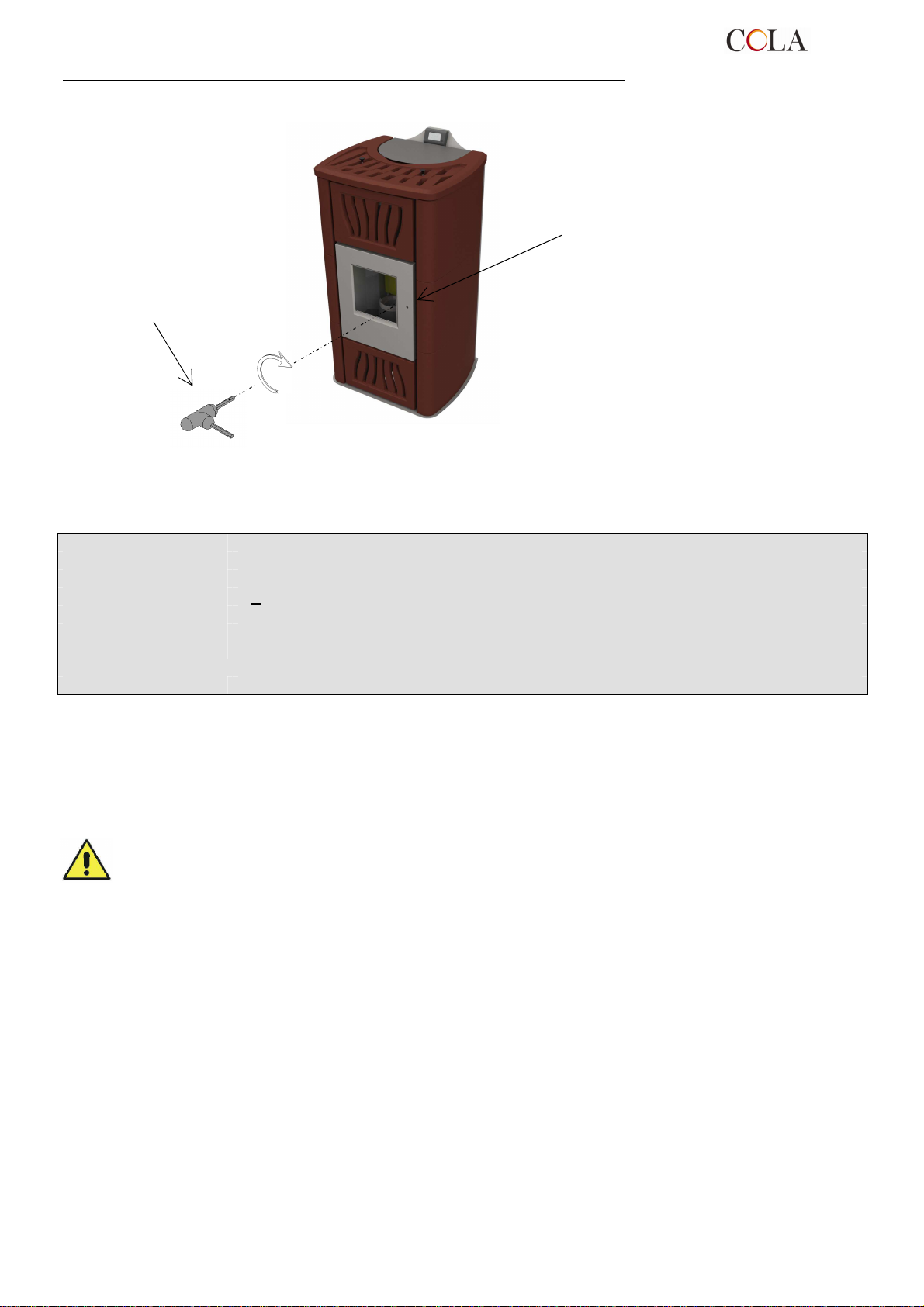
Apertura – chiusura porta fuoco termo-stufa a pellet TERMO POWER
Per aprire la porta inserire la
maniglia in dotazione e ruotare in
Maniglia apertura-chiusura
porta fuoco ;
- Apertura: senso antiorario
- Chiusura: senso orario
senso orario
1.5 Combustibile e uso consentito
Le stufe a pellet funzionano esclusivamente con pellet (pastiglie) di varie essenze di legno conformi alla normativa
DIN plus 51731 o UNI EN 14961-2 o Ö-Norm M 7135 ovvero aventi le seguenti caratteristiche :
Potere calorico : min 4.8 kWh/kg (4180 kcal/kg)
Densità: 680-720 kg
Umidità: max 10% del peso
Diametro: 6 +0.5 m
Percentuale ceneri: max 1.5% del peso
Lunghezza: min 6 mm- max 30 mm
Composizione: 100% legno non trattato dell’industria del legno o post consumo senza aggiunta di
sostanze leganti e privo di corteccia conforme alle normative vigenti
Imballo: in sacchi realizzati in materiale ecocompatibile o biologicamente decomponibile o in carta
Il serbatoio di contenimento del pellet si trova nella parte posteriore della stufa . Lo sportello di apertura è
posizionato nella parte superiore e il caricamento avviene manualmente solo a stufa spenta ponendo attenzione a
non farlo fuoriuscire dal serbatoio .
L’utilizzo di pellet con caratteristiche diverse rispetto a quello testato dal tecnico durante la 1°ac censione implica una
nuova taratura dei parametri di carico pellet della stufa , tale intervento è escluso dalla garanzia .
- Immagazzinare il pellet in luogo asciutto e privo di umidità .
- Ai fini di un funzionamento regolare ed efficiente non è possibile il caricamento manuale del pellet o
altri combustibili nel braciere
- Evitare il caricamento nel serbatoio di combustibili non conformi .
- Evitare il caricamento nel serbatoio di corpi estranei quali contenitori , scatole , sacchetti , metalli etc…
- L’utilizzo di pellet scadenti e non conforme , danneggia e compromette il funzionamento
dell’apparecchio facendo decadere la validità della garanzia con esclusione della responsabilità da
parte del costruttore .
1.6 Accessori in dotazione
La dotazione è comprensiva di :
Cavo alimentazione elettrica ;
Manuale d’installazione , uso e manutenzione ;
Chiave di apertura – chiusura ;
Telecomando .
1.7 Riferimenti normativi
Norma UNI 10683:2005 : Requisiti di installazione dei generatori di calore alimentati a legna o altri biocombustibili
solidi ;
Norma UNI EN14785:2006 : Requisiti di progettazione , fabbricazione , costruzione , sicurezza e prestazioni ,
Norma CEI EN 60335-1 : Sicurezza degli apparecchi elettrici d’uso domestico e similare – parte1 ;
istruzioni e marcature , unitamente ai relativi metodi di prova per le omologazioni
degli apparecchi funzionanti a pellet ;
TERMO-POWER
8
Page 9
Requisiti per elettrodomestici, attrezzi elettrici e
Norma CEI EN 60335-2-102 : Sicurezza degli apparecchi elettrici d’uso domestico e similare –parte 2 ;
Norma CEI EN 55014-1 : Resistenza elettromagnetica –
apparecchi elettrici simili – Parte 1: Emissione di disturbo ;
Norma CEI EN 55014-2 : Resistenza elettromagnetica – Requisiti per elettrodomestici, attrezzi elettrici e apparecchi
elettrici simili – Parte 2 : Immunità ; Norma famiglia di prodotti ;
Norma CEI EN 61000-3-2 : Limiti per le emissioni di corrente armonica ( Corrente ingresso ≤16 A per fase ) ;
Norma CEI EN 61000-3-3 : Limitazione delle fluttuazioni di tensione e del flicker in sistemi di alimentazione in bassa
tensione per apparecchiature con corrente nominale ≤ 16 A ;
Norma CEI EN 62233 : Metodi di misura per campi elettromagnetici degli apparecchi elettrici di uso domestico e
similari con riferimento all’esposizione umana .
Norme DIN plus 51731 – UNI EN14961-2 - Ö-Norm M 7135 : Norme riguardanti le specifiche e la classificazione
del pellet .
1.8 Targa di identificazione
La targa di identificazione è visibile sulla superficie interna dello sportello serbatoio pellet o sulla parete posteriore
della stufa. Su di essa sono riportati i seguenti dati:
Modello
►
Numero di matricola
►
Tipo di combustibile
►
Potenza termica nominale e ridotta
►
Consumo alla Pnom e Prid
►
Temperatura fumi alla Pnom e Prid
►
Rendimento termico
►
Tensione di alimentazione
►
Potenza elettrica assorbita
►
Dimensione tubo gas di scarico
►
Dimensione tubo di aspirazione
►
Tiraggio minimo
►
Dimensioni esterne stufa
►
Dimensioni attacchi idraulici
►
Distanza di sicurezza da materiali infiammabili
►
Peso
►
1.9 Messa fuori servizio della stufa
Nel momento in cui si decide di non utilizzare definitivamente la stufa, scollegare l’alimentazione elettrica e scaricare
completamente il pellet dal serbatoio. Per provvedere allo smaltimento della stufa, è necessario sigillarla all’interno
di un robusto imballo e contattare gli organismi locali preposti per queste operazioni in modo da procedere secondo
le norme locali vigenti, oppure riconsegnarla al rivenditore al momento dell’acquisto di una nuova apparecchiatura
similare .
Ai sensi dell’art.13 del Decreto Legislativo n°151 d el 25 luglio 2005 di attuazione della Direttiva 2002/96/CE del 23
Febbraio 2003 sui Rifiuti di Apparecchiature Elettriche ed Elettroniche relative alle misure e procedure finalizzate a
prevenire la produzione di rifiuti di apparecchiature elettriche ed elettroniche, denominate RAEE, promuovendo il
reimpiego , il riciclaggio e altre forme di recupero in modo da ridurne la quantità da avviare allo smaltimento e
migliorando l’intervento dei soggetti che partecipano al ciclo di vita di tali prodotti .
Il simbolo del cassonetto barrato riportato sull’etichetta dell’apparecchiatura indica che il prodotto alla fine della
propria vita utile deve essere raccolto separatamente dai altri rifiuti urbani .
1.10 Istruzioni per richiesta di intervento e ricambi
Per richiedere qualsiasi intervento e/o ricambio contattare il proprio rivenditore, importatore di zona o il centro di
assistenza autorizzato più vicino, esponendo in modo chiaro i seguenti dati: modello della stufa; numero di serie,
data di acquisto, lista dei ricambi e informazioni sulle anomalie o malfunzionamenti riscontrati.
- Gli interventi sui componenti devono essere effettuati da personale autorizzato e/o qualificato.
- Prima di ogni intervento accertarsi che sia disinserito ogni collegamento elettrico e che la stufa sia
fredda.
- Utilizzare solo ricambi originali.
2 TRASPORTO ED INSTALLAZIONE
2.1 Imballo, movimentazione, spedizione e trasporto
Il sollevamento della stufa completa di imballo può essere effettuato mediante carrello elevatore, inserendo le
forche, di adeguata lunghezza, nelle apposite sedi del bancale in legno. E’ necessario accertarsi che i dispositivi
utilizzati per il sollevamento e il trasporto siano in grado di sopportare il peso della stufa indicato sulla targhetta di
identificazione e sul presente manuale.
Evitare il passaggio del carico su zone nelle quali la caduta del carico può essere un pericolo.
Aprire l’imballo, rimuovere la stufa dal bancale e posizionarla nel luogo prescelto facendo attenzione che sia
conforme a quanto previsto seguendo le illustrazioni delle pagine seguenti .
Si raccomanda di adagiare la stufa sul pavimento con la massima cautela evitando qualsiasi urto e di posizionarla
nella zona preposta ; inoltre è indispensabile verificare la portata del pavimento in funzione del peso della stufa , in
caso contrario consultare un tecnico specializzato.
Lo smaltimento o il riciclaggio dell’imballo è a cura dell’utente finale in conformità alle norme locali vigenti in materia.
TERMO-POWER
9
Page 10
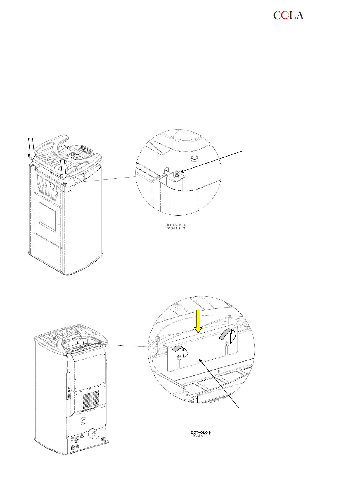
Antivibrante
2.1.1
Montaggio coperchio TERMO POWER
All’interno dell’imballo della stufa viene collocato il coperchio protetto e opportunamente confezionato :
- aprire la confezione con cautela , controllare l’integrità del pezzo e installarlo al termine del piazzamento della stufa
come segue :
X - posizionare il coperchio rispettando la posizione dei 2 antivibranti (dettaglio A) sulla stufa che permettono il
centraggio dello stesso .
Y - bloccare il coperchio in posizione fissando l’arresto centrale senza forzature come da figura .
X
Y
Arresto
TERMO-POWER
10
Page 11
X
4
4
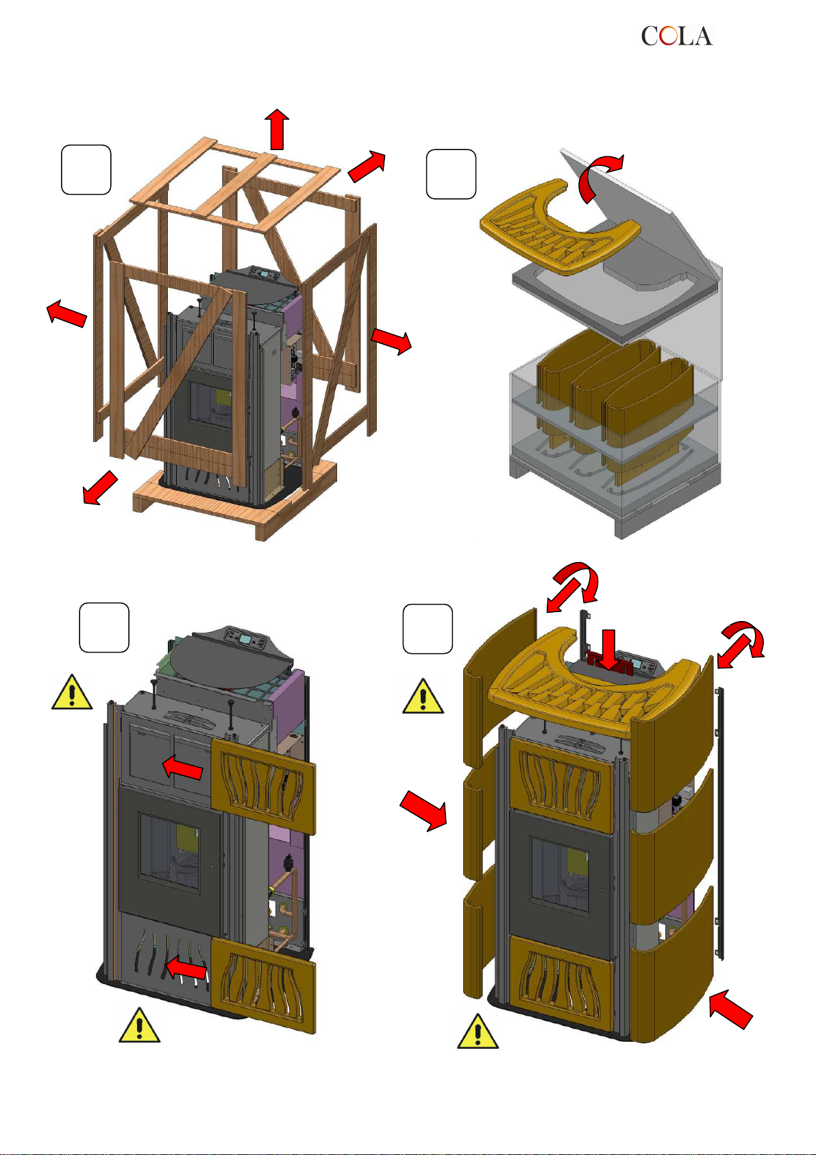
2.1.2
Montaggio maioliche TERMO POWER LUX
A
C
B
X
D
TERMO-POWER
11
Page 12
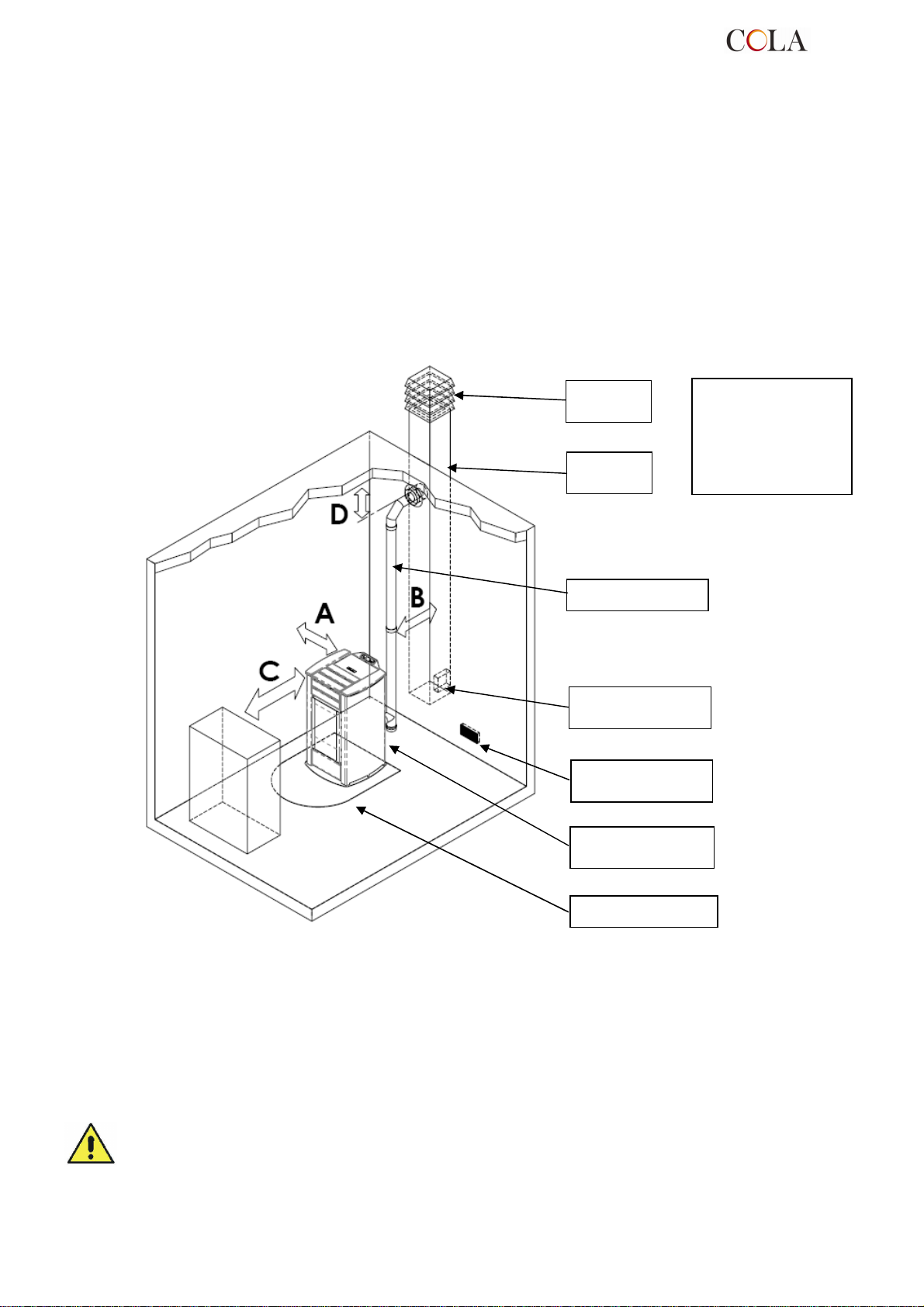
2.2 Luogo d’installazione, posizionamento e sicurezza antincendio
L’ambiente di installazione deve essere sufficientemente ventilato per consentire l’evacuazione di eventuali piccole
perdite di fumo di combustione.
L’apparecchio è idoneo al funzionamento in ambiente domestico con temperatura minima non inferiore a 0°C, viene
fornito completo della funzione antigelo, che attiva il funzionamento della pompa di riscaldamento x temperature
dell’acqua contenuta nell’impianto inferiori a 6°C, salvaguardando: termocamera, circuito di riscaldamento-sanitario.
La funzione antigelo è attiva solo a stufa alimentata elettricamente.
Per evitare il rischio di incendio è necessario proteggere dal calore le strutture circostanti la stufa. Per esempio i
pavimenti in legno o in materiale infiammabile devono essere opportunamente protetti con pannello in acciaio o
vetro temperato. Eventuali travature e tavole in legno poste sopra e attraversate dalla canna fumaria devono essere
opportunamente protette secondo le indicazioni delle specifiche norme vigenti di installazione. Per ogni evenienza è
consigliabile disporre di idonei dispositivi antincendio.
La distanza minima frontale per la protezione di oggetti infiammabili è di 1,5 m. Le distanze minime di sicurezza da
materiali infiammabili devono essere minimo di 0,2 m e comunque devono rispettare la tabella di seguito riportata :
Comignolo
antivento
Canna
fumaria
Raccordo fumi
Sportello ispezione
su canna fumaria
Presa d’aria a parete
min. 100 cm²
Raccordo a T con
tappo d’ispezione
A = 200 mm
B = 200 mm
C = 1500 mm
D = 200 mm
Base salva-pavimento
Ogni installazione deve prevedere uno spazio tecnico di manovra di facile accesso per eventuali manutenzioni .
La stufa è fornita di 4 piedini regolabili per facilitare il posizionamento in presenza di pavimenti non perfettamente
planari : per regolare l’altezza inclinare la stufa e ruotare il piedino interessato al livellamento .
La stufa viene fornita con la sonda ambiente fissata tramite un fascetta sulla parete posteriore della stufa ; si
consiglia la rimozione della fascetta e un posizionamento della sonda ideale per la migliore rilevazione della
temperatura nel contesto dell’ambiente e della lunghezza del cavo .
Per una rilevazione lontana dalla stufa si consiglia l’installazione di un termostato/cronotermostato ambiente – rif.
par.4.8.
- Non è ammessa l’installazione della stufa nelle camere da letto,nei bagni e in generale nei locali dove
è già installato un altro apparecchio da riscaldamento senza un afflusso di aria indipendente .
- In presenza di pavimento in legno installare una base salva-pavimento in conformità alle norme vigenti.
-
Per ogni evenienza è consigliabile disporre di idonei dispositivi antincendio .
- E’ vietato il posizionamento della stufa in ambienti con atmosfera esplosiva .
TERMO-POWER
12
Page 13
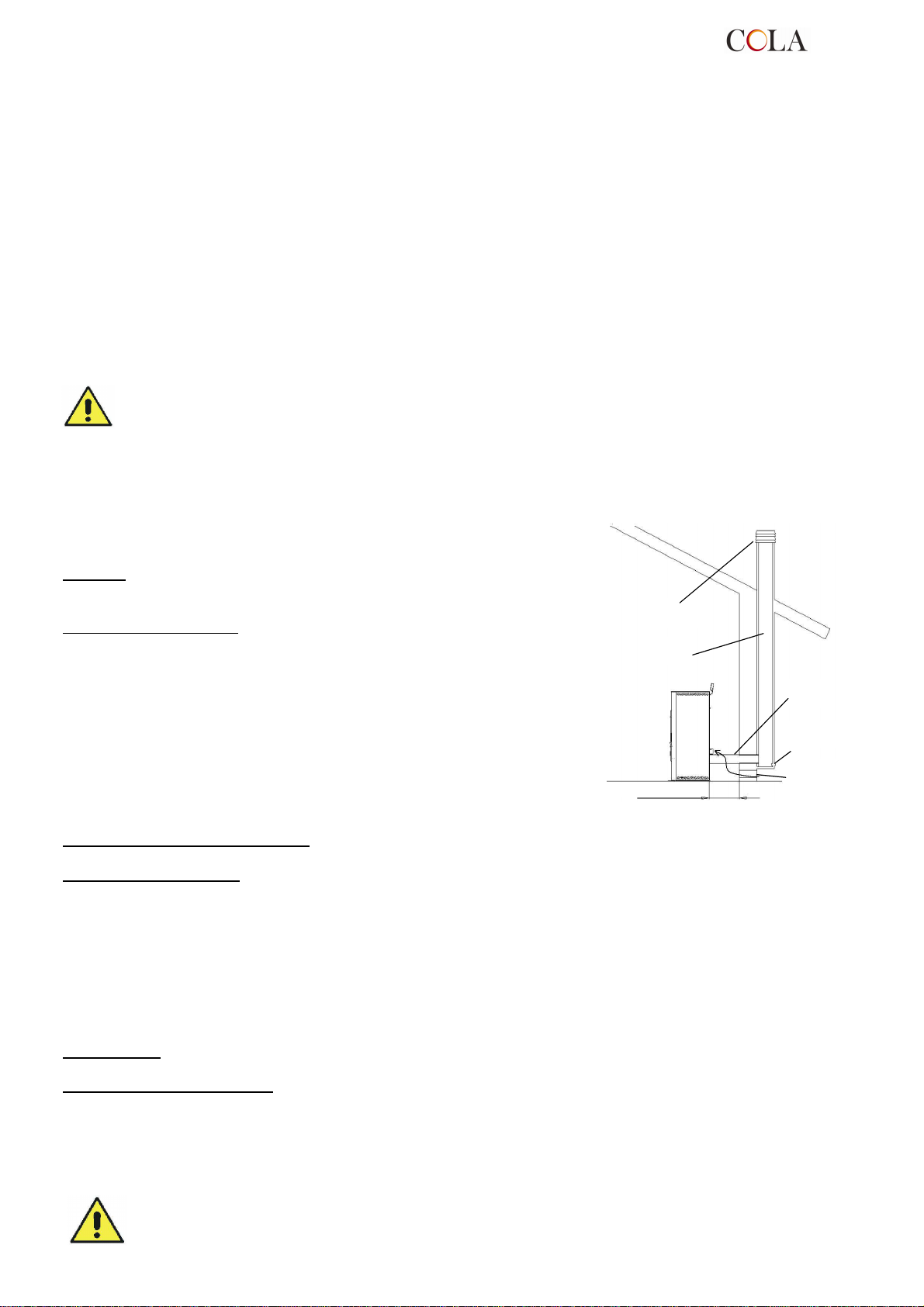
Canna
Comignolo
Presa d’aria
Camera
Distanza min 0.2m
Raccordo
2.3 Presa d’aria
Il condotto di aspirazione o presa d’aria della stufa è collocato posteriormente ed è di sezione circolare con diametro
pari a 50 mm.
L’aria di combustione può essere aspirata :
dall’ambiente a condizione che in prossimità della stufa sia praticata una presa d’aria a parete comunicante con
►
l’esterno di superficie minima di 100 cm² opportunamente posizionata da non essere ostruita e protetta
esternamente da una griglia ;
oppure con collegamento direttamente all’esterno con un appropriato tubo con diametro interno pari a 50mm e
►
con lunghezza massima di 1.5 m .
2.4 Scarico fumi di combustione
Lo scarico fumi può essere fatto attraverso un allacciamento ad una canna fumaria tradizionale.
- Si raccomanda all’installatore di verificare l’efficienza e lo stato della canna fumaria, la rispondenza alle
disposizioni regole locali, norme nazionali ed europee.
- E necessario utilizzare tubi e raccordi certificati con adeguate guarnizioni che garantiscono la tenuta.
- In caso di incendio spegnere la stufa , chiamare tempestivamente i pompieri ed evitare continui tentativi
di spegnimento.
2.4.1 Tipologie delle installazioni
Di seguito vengono elencate definizioni e requisiti per realizzare secondo
Norma italiana UNI10683 per la corretta installazione di uno scarico
fumario:
CAMINO : condotto verticale avente lo scopo di raccogliere ed espellere ad
un opportuna altezza dal suolo i prodotti di combustione provenienti da un
solo apparecchio e nei casi consentiti più di uno.
Requisiti tecnici CAMINO :- essere a tenuta dei prodotti di combustione,
isolato e coibentato in funzione dell’impiego ;
- avere un andamento prevalentemente verticale con deviazioni dall’asse
< 45° ;
- essere adeguatamente distanziato da materiali infiammabili con
intercapedine d’aria o isolante;
- avere sezione interna preferibilmente circolare , costante , libera ed
indipendente ;
- è consigliato che il camino sia dotato di camera ispezionabile per la
raccolta di materiali solidi
- ed eventuali condense collocato sotto l’imbocco del canale da fumo .
CANALE o RACCORDO da FUMO : condotto o elemento di collegamento tra apparecchio e camino per
l’evacuazione dei prodotti della combustione .
Requisiti tecnici CANALE : - non deve attraversare locali nel quali è vietata l’installazione di apparecchi da
combustione ;
- è vietato l’uso di tubi metallici flessibili o in fibro-cemento ;
- è vietato l’impiego di elementi in contro-pendenza ;
- nei tratti orizzontali devono avere andamento con pendenza minima del 3% verso l’alto ;
- la lunghezza del tratto orizzontale deve essere minima e non maggiore di 3 m ;
- il numero di cambi direzione , senza il raccordo a T non deve essere maggiore di 3 ;
- con cambio di direzione > 90° usare al max 2 curv e con lunghezza in proiezione orizzontale non maggiore di 2 m
- il canale da fumo deve essere a sezione costante e permettere il recupero della fuliggine .
COMIGNOLO :
combustione .
dispositivo posto alla sommità del camino atto a facilitare la dispersione in atmosfera dei prodotti della
Requisiti tecnici COMIGNOLO : - avere sezione equivalente a quella del camino ;
- avere sezione utile non minore del doppio di quella interna del camino ;
- deve impedire la penetrazione di pioggia e di corpi estranei ed in ogni condizione atmosferica assicurare lo
scarico dei prodotti di combustione ;
- deve garantire un adeguata diluizione dei prodotti ed essere posizionato al di fuori della zona di reflusso;
- deve essere privo di mezzi meccanici di aspirazione .
Lo scarico diretto dei prodotti della combustione deve essere previsto a tetto ed è vietato verso spazi
chiusi anche a cielo libero .
antivento
fumaria
fumi
ispezionabile
esterna
min.100 cm
2
TERMO-POWER
13
Page 14
2.5 Controllo posizione braciere e turbolatori
Prima di accendere la stufa è importante controllare che il braciere sia in posizione corretta ovvero alloggi negli
appositi incastri . Inoltre controllare che il dispositivo scuoti turbo latori sia a riposo ovvero in posizione inferiore .
Una posizione errata del braciere e/o turbo latori comporta malfunzionamenti ed un eccessivo annerimento del vetro.
Ad ogni accensione dell’apparecchio controllare la corretta posizione del braciere e del dispositivo di
scuotimento turbolatori .
2.6 Collegamento elettrico
Collegare il cavo di alimentazione elettrica da una parte alla presa posteriore della stufa e dall’altra su una presa
elettrica a parete .
La tensione fornita dall’impianto deve corrispondere a quella indicata sulla targhetta di identificazione della stufa, e
nel paragrafo relativo ai dati tecnici di questo manuale.
Nel periodo di inutilizzo della stufa è consigliabile togliere il cavo di alimentazione dalla stessa.
- Assicurarsi che l’impianto elettrico sia a norma, provvisto della messa a terra e dell’interruttore
differenziale secondo le Norme vigenti.
- Il cavo di alimentazione non deve mai toccare il tubo di scarico della stufa.
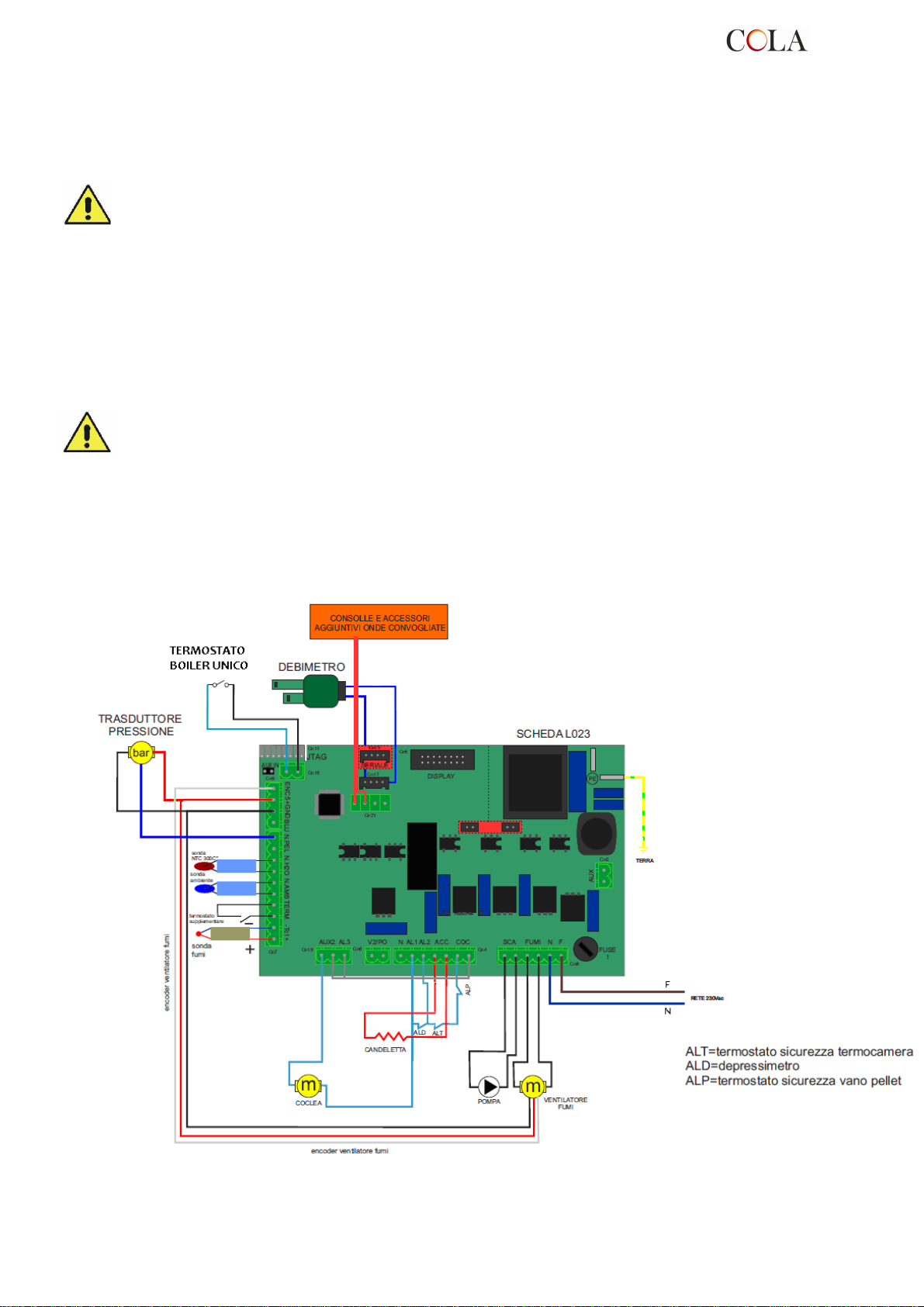
2.7 Schema elettrico
2.7.1 Schema elettrico base ( di serie su T-POWER 30 )
TERMO-POWER
14
Page 15
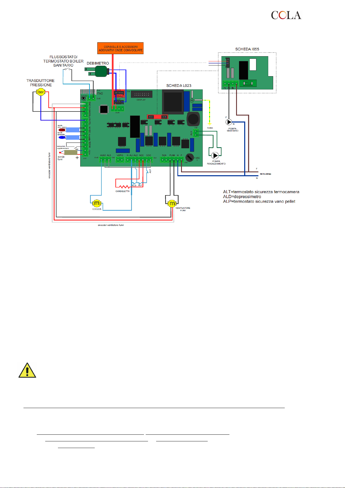
2.7.2 Schema elettrico con pompa sanitario
2.8 Schema elettrico per impianto a zone
Prima di installare la termostufa nell’abitazione verificare la tipologia dell’impianto di riscaldamento; se sono
presenti più zone, è necessario inserire un’apposita centralina elettronica per circuiti multizona disponibile come
optional. Questo al fine di evitare il surriscaldamento della termocamera per la possibile chiusura contemporanea
delle valvole di zona ed il conseguente blocco del flusso d’acqua calda.
2.9 Collegamenti idraulici
La potenzialità termica dell’apparecchio va stabilita preliminarmente con un calcolo del fabbisogno di calore
dell’edificio secondo le norme vigenti. L’impianto deve essere corredato di tutti i componenti per un corretto e
regolare funzionamento; infatti secondo le norme e la buona tecnica d’installazione devono essere interposti , fra
stufa ed impianto di riscaldamento , le valvole d’intercettazione e le valvole di non ritorno che permettano d’isolare la
stufa dall’impianto in caso di manutenzioni e/o controlli .
Durante il caricamento dell’acqua nella termo camera procedere lentamente per consentire la corretta e completa
evacuazione dell’aria dallo sfiato .
La stufa a pellets presenta al suo interno il circuito idraulico di riscaldamento e precisamente : circolatore , valvola di
sicurezza , sfiato aria , sonde di temperatura e trasduttore di pressione .
Si rende noto che qualora l’impianto di riscaldamento sia gestito a zone è indispensabile introdurre una centralina
multizona disponibile su richiesta .
Durante il trasporto della stufa si possono verificare allentamenti e/o cedimenti delle guarnizioni
dell’impianto idraulico causando delle perdite d’acqua durante il regolare funzionamento; a tale scopo si
raccomanda sia durante il caricamento d’acqua sia dopo le prime ore di funzionamento di controllare il
serraggio delle ghiere di attacco circolatori e termo camera nonché di scaricare i residui di aria rimasti
nell’impianto .
Per collegare la termostufa ad un impianto sanitario si consiglia di rivolgersi ad un tecnico competente al fine di
ottimizzare al meglio i collegamenti idraulici e le prestazioni dell’intero impianto senza compromettere la funzionalità
dell’apparecchio .
Per il collegamento al circuito sanitario è necessario richiedere uno dei seguent i optional :
- una pompa sanitario sul collettore di mandata
- oppure pompa sanitario, scambiatore a piastre e tubi di collegamento da collocare internamente alla stufa
- oppure una valvola a 3 vie monostabile da installare esternamente alla stufa .
con i relativi tubi di collegamento da collocare internamente alla stufa
TERMO-POWER
15
Page 16
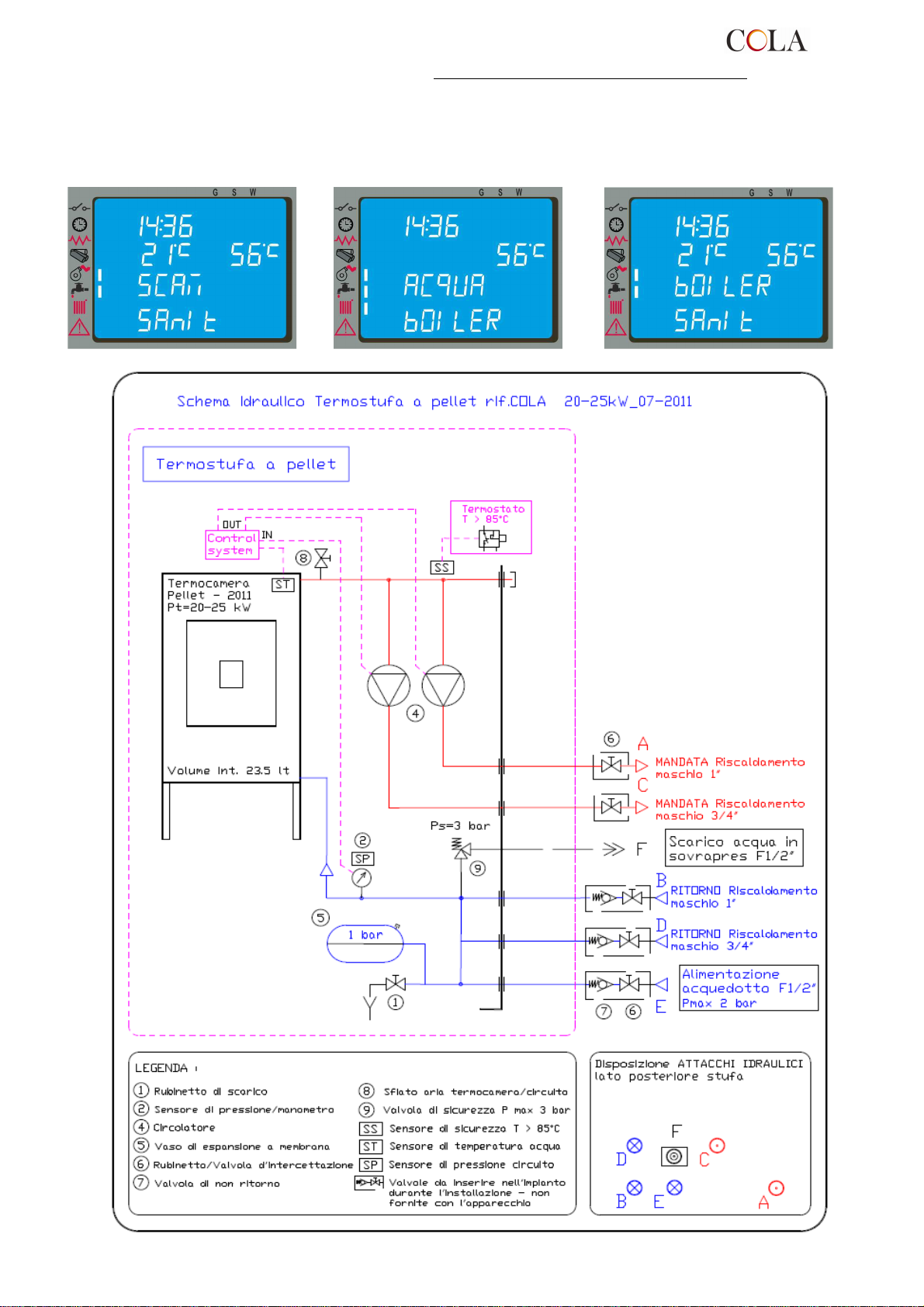
La richiesta di questi accessori va accompagnata alla scheda elettronica supplementare mod. ‘I055’ per la gestione
dei comandi con l’eventuale aggiornamento software da collocare sulla scheda base di controllo .
Completato il collegamento sanitario è necessario entrare nel menu tecnico del controllo e selezionare la tipologia
del circuito ; ogni specifica funzione sanitario impostata : SCAMBIATORE SANITARIO , BOILER o BOILER
SANITARIO compare sul display al momento della commutazione riscaldamento-sanitario con uno dei messaggi
sotto riportati e rimane fino al termine della richiesta di acqua calda sanitaria da termostato o flusso stato :
TERMO-POWER
16
Page 17
2.10 Pronto intervento
Per ogni evenienza è consigliabile disporre di idonei dispositivi antincendio .
Se si manifesta un incendio procedere come segue :
- Scollegare immediatamente la presa di corrente ;
- Spegnere tramite l’uso di estintori ;
- Richiedere l’immediato intervento dei vigili del fuoco ;
- Non spegnere il fuoco con l’uso di getti d’acqua .
3 SICUREZZE DELLA STUFA
3.1 Distanza sicurezza da materiali infiammabili
L’apparecchio va collocato ad una distanza minima perimetrale da materiali infiammabili al fine di evitare pericoli di
incendio secondo le indicazioni presenti nella tabella tecnica del manuale e riportate nella targa dello stesso.
Porre attenzione alla tipologia del pavimento : per materiali delicati ed infiammabili si raccomanda l’utilizzo di piastre
in acciaio o vetro temperato come base di appoggio ( vedere capitolo 2 - Trasporto ed Installazione) . In caso di
presenza di oggetti ritenuti particolarmente delicati quali mobili, tendaggi, divani aumentare considerevolmente la
distanza della stufa .
3.2 Sicurezza scarico fumi
Nel normale funzionamento, la camera di combustione è in depressione garantendo la tenuta da eventuali perdite di
fumo nell’ambiente. Nel caso in cui non si raggiunge un certo valore di vuoto o lo scarico di uscita dei fumi è ostruito,
il vacuostato capta la mancanza di depressione all’interno della camera di combustione oppure il debimetro rileva
l’assenza di flusso d’aria comburente che tramite il controllo elettronico interrompe il funzionamento del motore
rotazione coclea avvisando l’utente dell’anomalia con un messaggio sul pannello comandi ‘ AL8 MANCA DEPRESS
‘ o ‘ AL9 TIRAGGIO INSUFF ‘ .
3.3 Sicurezza sovrapressione in camera di combustione
Eventuali e/o improvvise sovrapressioni dei fumi di combustione all’interno della camera e dei condotti di
evacuazione dei fumi vengono scaricati attraverso l’apertura delle valvole di sicurezza poste sopra lo scambiatore di
calore. Durante il normale funzionamento queste valvole sono chiuse dal proprio peso e dalla depressione della
camera e garantiscano la tenuta contro l’eventuale uscita dei fumi.
Controllare periodicamente la chiusura, lo stato di integrità del dispositivo e il relativo funzionamento .
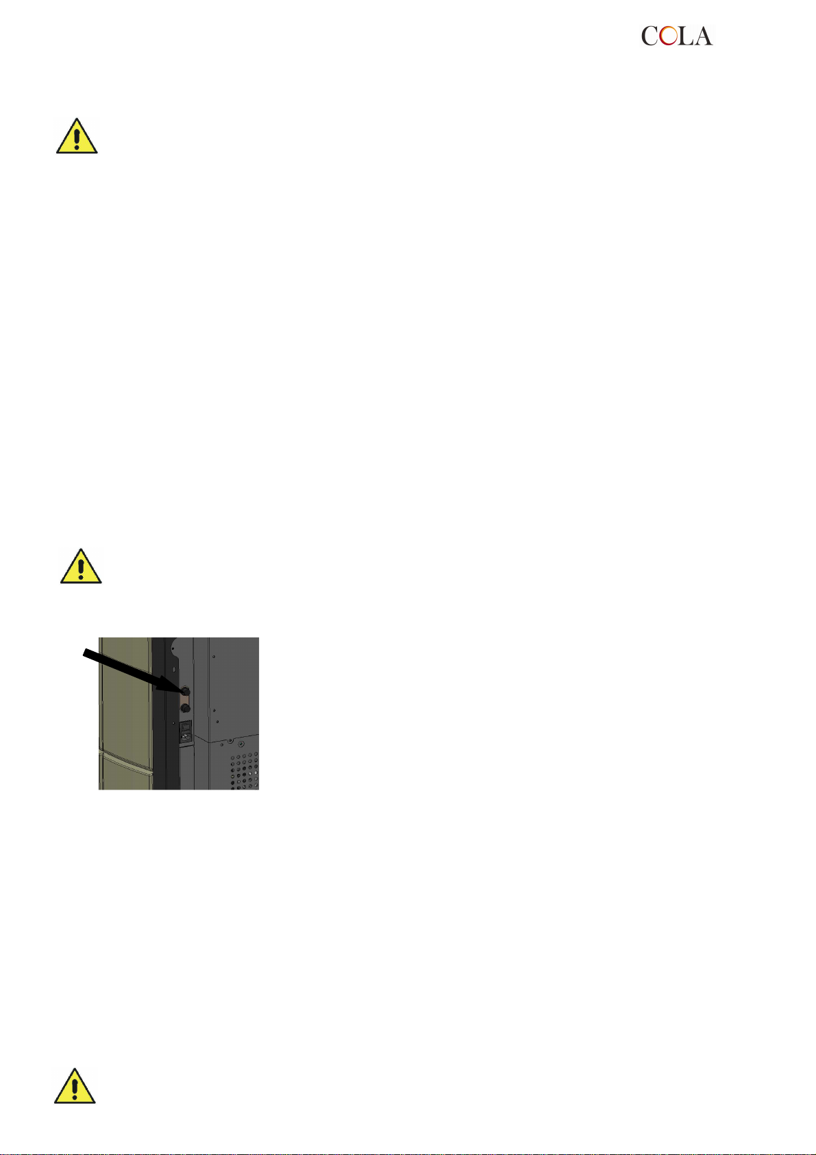
3.4 Surriscaldamento- termostati di sicurezza
Sulla parete inferiore del serbatoio, e precisamente sul convogliatore del pellet e
sulla parte più alta della termocamera sono posizionate due sonde di temperatura
collegate ai rispettivi termostati di sicurezza che in caso di eccessivo
riscaldamento disattivano automaticamente l’alimentazione del pellet. In tal caso
l’estrattore e/o ventilatori continuano a funzionare consentendo il rapido
raffreddamento dell’apparecchio. L’anomalia viene visualizzato sul pannello
comandi con il messaggio ‘ AL 7 SICUREZ-TERMICA ’. In caso di intervento
operare come segue:
Lasciare raffreddare la stufa per almeno 45 minuti.
►
Ripristinare il termostato premendo il pulsante vicino all’interruttore dietro la
►
stufa (figura a lato).
Riavviare la stufa come da normale avvio .
►
Temperatura d’intervento termostato serbatoio pellet : > 85°C
Temperatura d’intervento termostato termocamera : > 95°C
3.5 Sicurezza contro il ritorno di fiamma sul canale alimentazione pellet
Le soluzioni che impediscono il ritorno di fiamma sono:
depressione in camera di combustione ved. par 3.2.
►
la forma a sifone del canale di alimentazione pellet.
►
la sicurezza sulla temperatura del serbatoio ved. par 3.4.
►
►
3.6 Dispositivo elettrico di protezione dalla sovracorrente
L’apparecchio è protetto contro la sovracorrente da fusibile/i da 2A inseriti sull’alimentazione dell’interruttore
generale della stufa dislocato posteriormente .
3.7 Sicurezza da interruzione di alimentazione elettrica
La mancanza temporanea dell’alimentazione elettrica non limita la sicurezza della stufa e la temperatura del
serbatoio non raggiunge valori elevati (< 85°C) vis te la modesta quantità di pellet in combustione nel braciere.
Tale anomalia può creare una breve fuori uscita di fumi nell’ambiente che non comporta alcun pericolo .
E’ vietato manomettere i dispositivi di sicurezza .
TERMO-POWER
17
Page 18
Display LCD retroilluminato
3.8 Sicurezza sovrapressione circuito idraulico
Eventuale sovrapressione dell’acqua all’interno della camera , per P>3 bar , viene scaricata attraverso l’intervento
della valvola di sicurezza installata sull’impianto idraulico interno alla stufa .
E’ vietato manomettere i dispositivi di sicurezza .
3.9 Guasto ventilatore estrazione fumi
Se per qualsiasi motivo il ventilatore di estrazione fumi si ferma , il controllo elettronico blocca istantaneamente la
fornitura di pellet visualizzando il messaggio ‘AL4 ASPIRAT-GUASTO’ .
4 USO DELLA STUFA
4.1 Premessa
La stufa a pellet presenta il vantaggio di unire il calore della fiamma del legno, alla comodità della gestione
automatica della temperatura con la possibilità di programmare settimanalmente l’accensione e lo spegnimento .
E possibile eseguire il collegamento ad un termostato e/o cronotermostato esterno per la rilevazione della
temperatura in un punto diverso da quello in cui è collocata la stufa.
Per un utilizzo sicuro e affidabile è consigliato osservare le seguenti prescrizioni :
- con la prima messa in funzione si possono riscontrare cattivi odori , pertanto si deve provvedere ad una buona
aerazione della stanza, soprattutto durante il primo periodo di funzionamento ;
- il caricamento del serbatoio deve essere fatto esclusivamente con pellet, durante tale operazione evitare che il
sacco venga a contatto con le superfici calde della stufa ;
- non inserire nel serbatoio nessun altro tipo di combustibile che non sia pellet conforme a quanto prescritto;
- l’apparecchio non deve essere utilizzato come inceneritore di rifiuti ;
- la stufa deve funzionare solo ed esclusivamente con la porta fuoco sempre chiusa .
- le guarnizioni della porta fuoco vanno controllate periodicamente per evitare che vi siano infiltrazioni d’aria ;
- per garantire un efficiente rendimento termico ed una corretta funzionalità è necessario effettuare la pulizia
periodica del braciere ad ogni carico pellet ;
- alla prima accensione è importante non surriscaldare la stufa ma portarla gradatamente in temperatura
impostando temperature di funzionamento basse ( vedere paragrafo impostazione temperatura ) ;
- la stufa durante l’accensione, funzionamento e spegnimento, a causa delle dilatazioni termiche a cui è soggetta,
può generare leggeri scricchiolii .
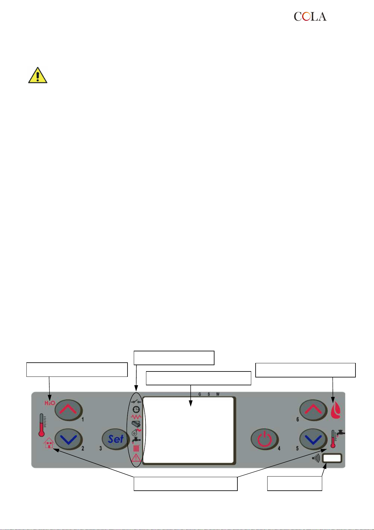
4.2 Descrizione del pannello comandi
Il pannello comandi è costituito da un display LCD retroilluminato , dal tasto di accensione/spegnimento ‘P4’ , dal
tasto funzione SET/MENU ‘P3’ , dai quattro tasti menu ‘P1’, ‘P2’, ‘P5’ ,‘P6’ e da 7 led indicanti lo stato di
funzionamento della stufa .
Indicazioni display superiore
Segnalatori di stato
Indicazioni display superiore
TERMO-POWER
Indicazioni display inferiore
18
Ricevitore IR
Page 19
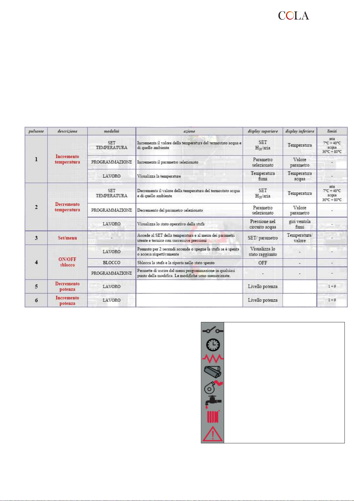
Il pannello consente l’accensione e lo spegnimento della stufa , la regolazione durante il funzionamento e permette il
settaggio dei programmi di gestione e manutenzione .
Sul display sono visualizzate tutte le informazioni sullo stato di funzionamento della stufa .
Per accedere ai menu procedere come segue :
- premere il tasto SET ‘P3’ ;
- premere i tasti ‘P5’ , ‘P6’ per scorrere i vari menù ;
- premere su uno dei tasti di incremento/decremeto ‘P1’, ‘P2’ per settare il parametro desiderato ;
- premere il tasto SET ‘P3’ per confermare il valore del parametro .
Accedendo al menu è possibile ottenere i vari tipi di visualizzazione ed effettuare le impostazioni disponibili a
seconda del livello di accesso .
Di seguito è riportata la tabella dei comandi e dei relativi messaggi visualizzati in fase di programmazione o
impostazione dei parametri operativi :
Decrementa la potenza o il valore della Temperatura
termostato acqua del boiler sanitario ( se abilitato )
Incrementa la potenza o il valore della Temperatura
termostato acqua del boiler sanitario ( se abilitato )
La Figura a fianco descrive il significato dei segnalatori di stato
sulla parte sinistra del display .
L’attivazione nel display di uno dei segmenti segnala l’attivazione
del dispositivo corrispondente secondo l’elenco a fianco .
Temperatura
SET sanitario
Temperatura
SET sanitario
Contatto esterno
Crono
Resistenza elettrica
Coclea
Estrattore fumi
Attivazione Circuito SANITARIO
Attivazione Circuito RISCALDAMENTO
ALLARME
TERMO-POWER
19
Page 20
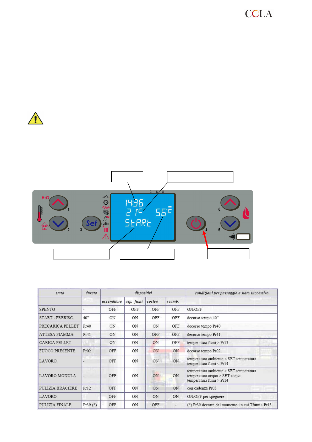
Finestra di dialogo
Pulsante ‘P4’
4.3 Accensione
4.3.1 Controllo prima dell’accensione
Prima di procedere con l’accensione della stufa è necessario verificare i seguenti punti :
- assicurarsi di aver letto e compreso quanto riportato nel manuale ;
- il serbatoio deve essere carico di pellet ;
- la camera di combustione deve essere pulita ;
- il braciere deve essere completamente libero, pulito da eventuali residui di combustione e posizionato
correttamente nella sede del portabraciere ;
- verificare la chiusura ermetica della porta fuoco e del cassetto cenere ;
- verificare il collegamento del cavo elettrico e la commutazione in ON/1 dell’interruttore collocato posteriormente
alla stufa .
- verificare l’apertura delle valvole di intercettazione mandata e ritorno nonché la pressione del circuito idraulico.
- Alla prima messa in funzione togliere dal focolare della stufa e del vetro tutti i componenti che
potrebbero bruciare ( istruzioni/etichetta ) .
- Eventuali accensioni eseguite a seguito di lunghe inattività dell’apparecchio richiedono il ripristino di
eventuali residui di pellet giacenti da tempo all’interno del serbatoio in quanto combustibile umido non
più idoneo alla combustione e una pulizia completa della camera di combustione .
4.3.2 Fase di avvio
Per accendere la stufa premere il pulsante ‘P4’ per 3 secondi : sul display comparirà la scritta ‘START’ .
Questa fase è automatica ed è completamente gestita da controllo elettronico senza alcuna possibilità di intervenire
sui parametri .
Orologio
Temperatura ambiente
La stufa esegue in sequenza le fasi di avvio secondo le modalità definite dai parametri che ne gestiscono livelli e
tempistica raggiungendo la condizione di lavoro a meno che non insorgono anomalie o allarmi secondo il prospetto
seguente :
Temperatura acqua
TERMO-POWER
20
Page 21
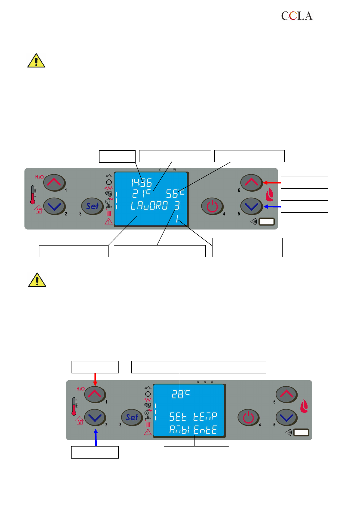
Finestra di dialogo
Pulsante ‘P6’
fisso
Finestra di dialogo
Pulsante ‘P
1’
Pulsante ‘P
2’
Trascorso un certo tempo , se la temperatura fumi non ha raggiunto il valore minimo ammesso la stufa si pone in
stato di allarme .
- E’ vietato utilizzare liquidi infiammabili per l’accensione .
- In caso di continue mancate accensioni contattare il Centro di Assistenza .
In alternativa è possibile accendere la stufa premendo contemporaneamente il pulsante P4 e P5 per 3 secondi. Sul
display compare la scritta ATTESA RICHIESTA. Con questa modalità la stufa si pone in uno stato di attesa ed
esegue la fase di accensione-start solo se viene riconosciuta una richiesta di calore, ad esempio per riscaldare
l’ambiente o per l’acqua calda sanitaria (se disponibile).
4.4 Fase di lavoro
Conclusa in modo positivo la fase di ‘AVVIO’ , la stufa passa alla modalità ‘LAVORO ‘ che rappresenta il normale
modo di funzionamento .
L’utente può regolare la potenza di riscaldamento attraverso i pulsanti ‘P6’ e ‘P5’ dal valore massimo di 5 ad un
valore minimo di 1 .
Orologio
Temperatura ambiente
Temperatura acqua
Pulsante ‘P5’
Potenza impostata a 3 –
Potenza reale in lavoro
pari a 1 - lampeggiante
- Si raccomanda di controllare il livello del pellet nel serbatoio per evitare che la fiamma si spenga per
mancanza di pellet .
- Durante il caricamento del pellet assicurarsi che l’apparecchio sia spento .
- Il coperchio del serbatoio pellet deve rimanere sempre chiuso , va aperto solamente durante il
caricamento del combustibile .
- I sacchi di pellet devono essere riposti lontano dalla stufa almeno 1,5 m .
4.4.1 Modifica impostazione temperatura ambiente
Per modificare la temperatura ambiente è sufficiente selezionare la modalità MODIFICA SET AMBIENTE con la
pressione sul pulsante P2 .
Agire successivamente sui pulsanti ‘P1’ e ‘P2’ : il display visualizza lo stato corrente del SET di temperatura .
Valore impostato della Temperatura ambiente
TERMO-POWER
21
Page 22
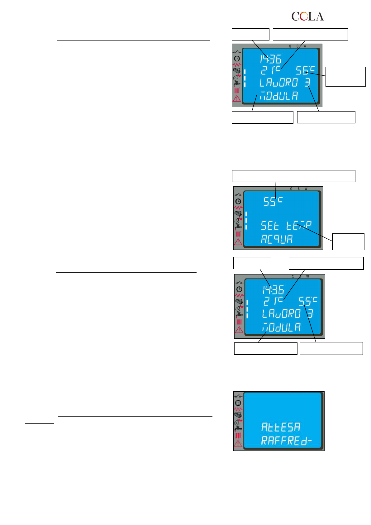
Orologio
Temperatura
ambiente
Finestra di dialogo
Potenza
impostata
Temperatura
acqua
Valore impostato temperatura acqua
Orologio
Finestra di dialogo
Quando la temperatura ambiente ha raggiunto il valore impostato
oppure la temperatura fumi ha raggiunto il valore massimo settato,
la potenza viene automaticamente portata al valore minimo ,
condizione di MODULAZIONE .
Se viene attivata la modalità STAND-BY , la stufa si spegne con
un tempo di ritardo dopo aver raggiunto il SET di temperatura.Il
riavvio avviene dopo che la temperatura ambiente è inferiore ad un
certo valore prefissato rispetto alla temperatura ambiente .
Quando la temperatura dei fumi arriva ad un valore massimo
impostato compare sul pannello di controllo il messaggio ‘MODULA
F’ e la stufa attiva la procedura di modulazione della fiamma senza
alcun intervento dell’utente mentre se la temperatura supera i
280°C appare l’allarme ‘ALLARM HOT FUMI ‘e la stufa attiva la
procedura di spegnimento .
4.4.2 Modifica impostazione temperatura acqua
Per modificare la temperatura ambiente è sufficiente selezionare la
modalità MODIFICA SET ACQUA con la pressione sul pulsante P1.
Agire successivamente sui pulsanti ‘P1’ e ‘P2’ : il display visualizza
lo stato corrente del SET di temperatura .
Quando la temperatura acqua ha raggiunto il valore impostato ,
come condizione anche contemporanea a quella descritta nel
par.4.4.1, la potenza viene automaticamente portata al valore
minimo , condizione di MODULAZIONE .
Nella versione idro la condizione di set Temperatura acqua non
soddisfatta viene visualizzata con l’attivazione del segmento/led [A].
4.4.3 Riavvio da STAND-BY
Dopo l’avvenuto spegnimento , la stufa si pone in condizione di
raffreddamento portando la velocità dell’estrattore fumi al valore
impostato per la pulizia braciere . La riaccensione avviene non
appena la temperatura ambiente ha raggiunto il valore di SET
impostato .
Temperatura ambiente
Temperatura acqua
Finestra
di dialogo
TERMO-POWER
22
Page 23
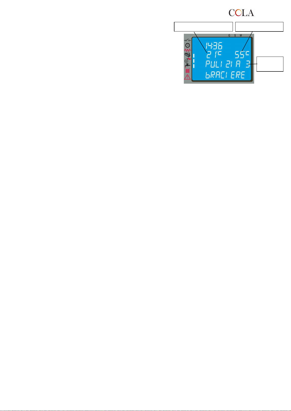
Temperatura ambiente
impostata
Temperatu acqua
4.4.4 Pulizia del braciere
Durante la normale operatività nella modalità lavoro , a intervalli
prestabiliti da parametro viene attivata la modalità ‘PULIZIA
BRACIERE’ per una durata prefissata .
Potenza
4.4.5 Acqua calda sanitaria con scambiatore rapido
Quando viene richiesta acqua calda sanitaria, nel display compare la scritta SCAM SANIT e si accende il LED
indicato dal rubinetto. La funzione, comunque, viene eseguita solamente se la stufa è accesa, ed ha raggiunto una
sufficiente temperatura dell’acqua all’interno della termocamera.
Nei restanti casi il servizio non viene fornito.
4.4.6 Acqua calda sanitaria con bollitore ad accumulo
Questo tipo di installazione richiede l’utilizzo di un termostato esterno, che misuri la temperatura dell’acqua sanitaria
del bollitore. Quando la temperatura si abbassa al di sotto della temperatura di SET impostata nel termostato esterno
si attiva la funzione sanitario , nel display della stufa compare la scritta BOILER SANIT e si accende il LED indicato
dal rubinetto fintantoché viene soddisfatta la richiesta .
Se la stufa è nella fase di ATTESA RICHIESTA si accende automaticamente e si pone in LAVORO. Raggiunta la
temperatura di lavoro dell’acqua nella termocamera, si attiva la fornitura d’acqua al bollitore.
Quando la temperatura di SET del bollitore è soddisfatta, la stufa converte il calore residuo all’impianto di
riscaldamento per circa 2 minuti e poi, se non c’è ulteriore richiesta, si pone in ATTESA RICHIESTA o in
MODULAZIONE, a seconda delle impostazioni (vedi prg. 4.6.5).
Se la stufa è nello stato SPENTO, non si accende e non fornisce il servizio.
4.4.7 Impianto con puffer / accumulatore di calore
Questo tipo di installazione richiede l’utilizzo di un termostato esterno, che misuri la temperatura dell’acqua del puffer.
Quando la temperatura si abbassa al di sotto della temperatura di SET impostata nel termostato esterno, nel display
della stufa compare la scritta ACQUA PUFFER o ACQUA BOILER e si accendono i 2 LED indicati rispettivamente
dal rubinetto e dal radiatore in quanto può soddisfare l’impianto di riscaldamento e sanitario .
Se la stufa è nella fase di ATTESA RICHIESTA si accende automaticamente e si pone in LAVORO e raggiunta la
temperatura di lavoro dell’acqua nella termocamera, si attiva la fornitura d’acqua al puffer .
Quando la temperatura di SET del puffer è soddisfatta, la stufa si pone in ATTESA RICHIESTA (si raccomanda di
impostare la funzione di STAND-BY su ON, vedi prg. 4.6.5).
Se la stufa è nello stato SPENTO, non si accende e non fornisce il servizio.
TERMO-POWER
23
Page 24
Orologio
Temperatura ambiente
Temperatura ambiente
4.5 Spegnimento
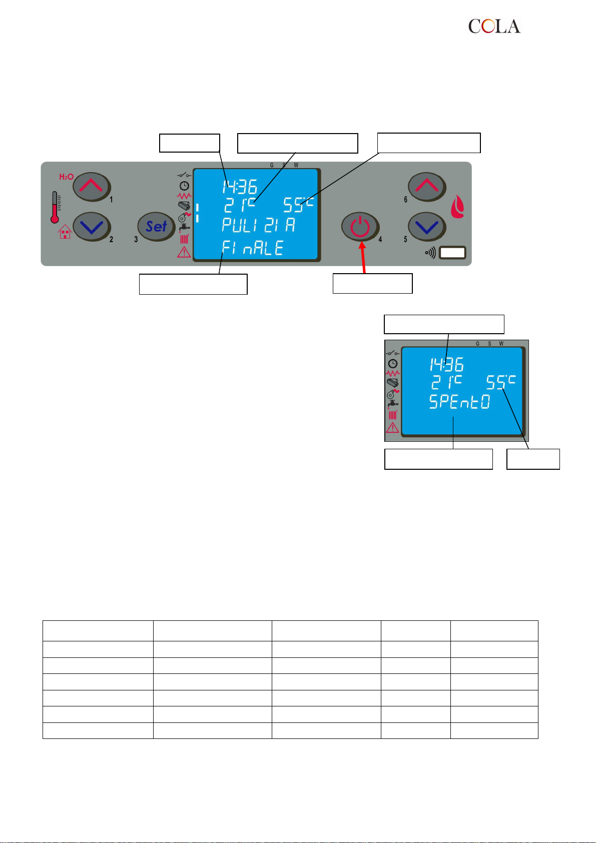
Per spegnere la stufa è sufficiente premere sul pulsante ‘P4’ per circa 2 secondi .
La coclea è immediatamente arrestata e l’estrattore fumi viene portato a velocità elevata facendo apparire sul
display la scritta ‘PULIZIA FINALE’ .
Temperatura acqua
Finestra di dialogo
Pulsante ‘P4’
Al termine dell’operazione comparirà sul display nella finestra di
dialogo la scritta ‘SPENTO’ .
Durante la fase di spegnimento non è possibile riavviare la stufa
fino a che la temperatura fumi non è scesa al di sotto di un valore
prefissato per un tempo prestabilito , visualizzando sulla finestra di
dialogo la scritta ‘ATTESA RAFFRED’ .
Finestra di dialogo T acqua
4.6 Menu
Premendo il tasto ‘P3’ ( SET ) si accede al menu ; questo è suddiviso in varie voci e livelli che permettono di
accedere alle impostazioni del controllo elettronico .
Il prospetto seguente sintetizza la struttura del menu con le sole selezioni disponibili per l’utente .
Livello 1 Livello 2
Livello 3
Livello 4
Valore
02 – set orologio
02 - ore Ore
03 - minuti Minuti
04 - giorno Giorno
05 - mese Mese
06 - anno Anno
TERMO-POWER
01 - giorno Giorno
24
Page 25

Livello 1 Livello 2
03 – set crono
01 – abilita crono on / off
01 – crono giorno on / off
02 – start 1 giorno ora
03 – stop 1 giorno ora
04 – start 2 giorno ora
05 – stop 2 giorno ora
01 – crono settim on / off
02 – start 1 giorno ora
03 – stop 1 giorno ora
04 – lunedi prog 1 on / off
05 – martedi prog 1 on / off
06 – mercoledi prog 1 on / off
07 – giovedi prog 1 on / off
08 – venerdi prog 1 on / off
09 – sabato prog 1 on / off
10 – domenica prog 1 on / off
11 – start prog 2 ora
12 – stop prog 2 ora
13 – lunedi prog 2 on / off
14 – martedi prog 2 on / off
15 – mercoledi prog 2 on / off
16 – giovedi prog 2 on / off
17 – venerdi prog 2 on / off
18 – sabato prog 2 on / off
19 – domenica prog 2 on / off
20 – start prog 3 ora
21 – stop prog 3 ora
22 – lunedi prog 3 on / off
23 – martedi prog 3 on / off
24 – mercoledi prog 3 on / off
25 – giovedi prog 3 on / off
26 – venerdi prog 3 on / off
27 – sabato prog 3 on / off
28 – domenica prog 3 on / off
29 – start prog 4 ora
30 – stop prog 4 ora
31 – lunedi prog 4 on / off
32 – martedi prog 4 on / off
33 – mercoledi prog 4 on / off
34 – giovedi prog 4 on / off
35 – venerdi prog 4 on / off
36 – sabato prog 4 on / off
37 – domenica prog 4 on / off
01 – crono week-end on / off
02 – start 1
01 – abilita crono
02 – program giorno
03 – program settim
04 – program week-end
Livello 3
Livello 4
Valore
03 – stop 1
04 – start 2
05 – stop 2
TERMO-POWER
25
Page 26
Input
Livello di menu
Input
Livello 1 Livello 2
Livello 3
Livello 4
Valore
04 – scegli lingua
01 - italiano set
02 - francese set
03 - inglese set
04 - tedesco set
05 – modo stand-by
06 – cicalino
07 – carico iniziale
08 – stato stufa
on / off
on / off
set
-
4.6.1 Menu 01 – regola ventole
La voce di menu 01 ,se abilitata regola la velocità dei ventilatori supplementari ( non disponibili ) .
Nella versione canalizzabile il collegamento elettrico viene visualizzato con l’attivazione dei due segmenti/led [ B ].
4.6.2 Menu 02 – set orologio
Prima di operare con la stufa è necessario impostare l’ora e la data corrente affinchè si abbia un riferimento per le
possibili programmazioni sul crono .
Il controllo elettronico è provvisto di batteria al litio mod. CR2032 da 3 Volt che permette all’orologio interno un
autonomia superiore ai 4-5 anni ; qualora a stufa spenta l’orologio non mantiene l’orario o alla riaccensione viene
visualizzato una serie di zeri è necessario procedere alla sostituzione chiamando un centro di assistenza
autorizzato.
4.6.3 Menu 03 – abilita crono
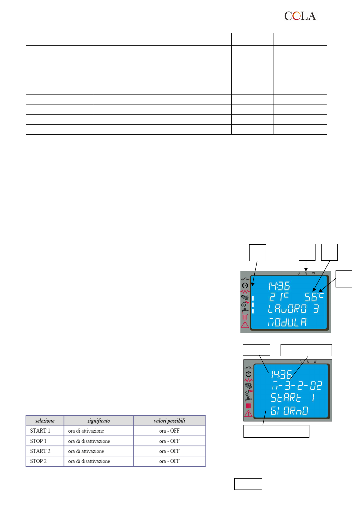
Permette di abilitare e disabilitare tutte le funzioni del cronotermostato ; con
la selezione ON si attiva la funzione e viene visualizzata il relativo
segmento/led [ D ]
Quando viene inserita la programmazione Giornaliera , Settimanale o Week
End nella parte superiore del display a destra appare rispettivamente il
segmento/led appropriato [ C ].
Per quanto riguarda le selezioni e l’inserimento degli orari è necessario
agire sui sei pulsanti attenenendosi alla tabella del paragrafo 4.2 .
D
C
B
Entrando nel sottomenu : PROGRAM GIORNO è possibile
abilitare , disabilitare e impostare le funzioni del cronotermostato
giornaliero .
E’ possibile settare due fase di funzionamento delimitate dagli
orari impostati secondo la tabella seguente dove l’impostazione
OFF indica all’orologio di ignorare il comando .
A
TERMO-POWER
Finestra di dialogo
26
Page 27
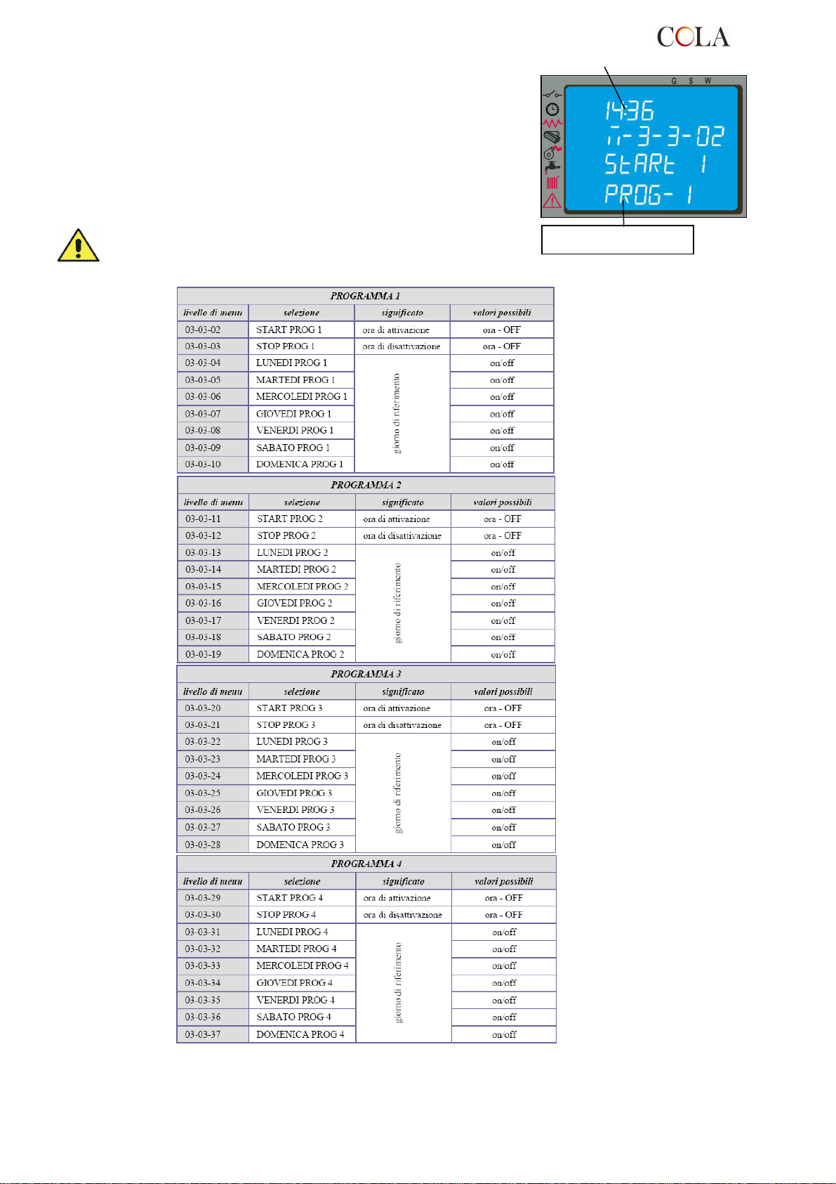
Entrando nel sottomenu : PROGRAM SETTIM è possibile
abilitare , disabilitare e impostare le funzioni del cronotermostato
settimanale .
Il programmatore settimanale dispone di 4 programmi
indipendenti il cui effetto finale è composto dalla combinazione
delle 4 programmazioni .
Il programmatore settimanale può essere attivato o disattivato ,
inoltre , impostando OFF nel campo orari , l’orologio ignora il
comando corrispondente .
Effettuare la programmazione con attenzione evitando di
far sovrapporre le ore di attivazione e/o disattivazione
nello stesso giorno in differenti programmi .
Finestra di dialogo
TERMO-POWER
27
Page 28
Pulsante ‘P4’
Pulsante ‘P
1’
Livello di menu
Livello di menu
Livello di menu
Finestra di dialogo
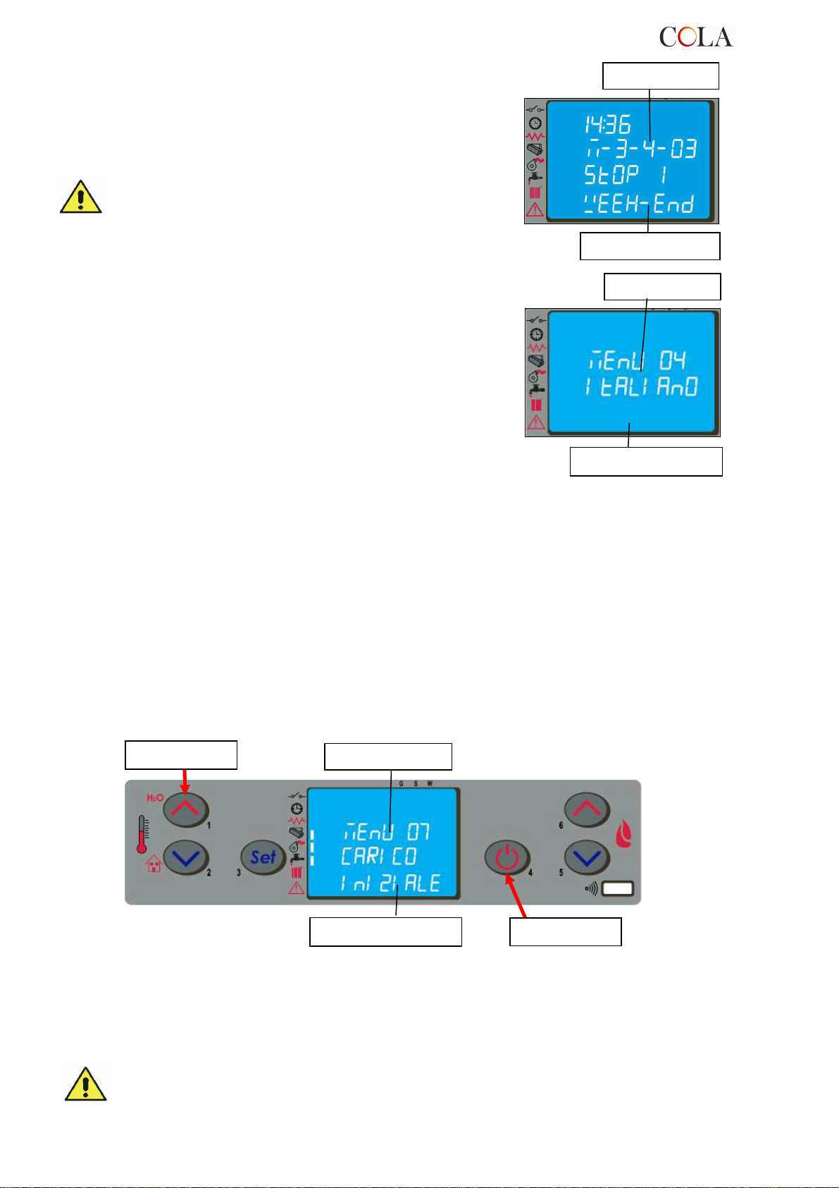
Entrando nel sottomenu : PROGRAM WEEK-END è possibile
abilitare , disabilitare e impostare le funzioni del cronotermostato
nel week-end ( fine settimana : sabato – domenica ).
Attivare la programmazione WEEK-END solamente
dopo aver disattivato la programmazione settimanale .
Al fine di evitare operazioni di avvio e spegnimento non
voluti , attivare un solo programma per volta .
Disattivare il programma giornaliero se si desidera
impiegare quello settimanale ; con questa impostazione
è opportuno disattivare il programma week-end .
4.6.4 Menu 04 – scegli lingua
Con questa selezione è possibile selezionare la lingua di dialogo
tra quelle disponibili inserite nel menu e precisamente :
- ITALIANO
- FRANCESE
- INGLESE
- TEDESCO
Finestra di dialogo
4.6.5 Menu 05 – modo stand-by
Con la selezione ON nella modalità STAND-BY la stufa si spegne automaticamente dopo che la temperatura
ambiente o la temperatura dell’acqua è rimasta superiore al valore di SET per un tempo prefissato.
La successiva riaccensione in automatico sarà possibile solamente quando la temperatura ambiente o dell’acqua
scende al di sotto di valore prestabilito inserito nella tabella parametri ( default 2°C ).
I comandi manuali da pannello camandi o da telecomando sono prioritari rispetto alla programmazione .
Con la selezione OFF la stufa non attiva la modalità STAND-BY e funziona normalmente attivando la funzione
MODULAZIONE quando la temperatura supera il valore di SET .
4.6.6 Menu 06 – cicalino
Con questa selezione è possibile attivare o disattivare la segnalazione acustica della stufa.
4.6.7 Menu 07 – carico iniziale
L’impostazione del CARICO INIZIALE consente di effettuare , a stufa spenta o fredda, un precarico pellet per un
tempo pari a 90 sec . Si avvia con il pulsante P1 e si interrompe con il pulsante P4 .
.
Finestra di dialogo
4.6.8 Menu 08 – stato stufa
Con tale selezione è possibile visualizzare lo stato istantaneo della stufa riportando la condizione di funzionamento
dei vari dispositivi ad essa collegati ; per il monitoraggio sono disponibili diverse pagine poste in successione .
4.6.9 Menu 09 – tarature tecnico
Tale selezione è riservata al solo tecnico autorizzato del centro di assistenza COLA .
La modifica dei parametri tecnici sul menu 09 deve essere effettuata da personale autorizzato e
competente ; eventuali modifiche fatte in modo casuale possono provocare gravi danni che escludono da
qualsiasi responsabilità la ditta COLA .
TERMO-POWER
28
Page 29
L
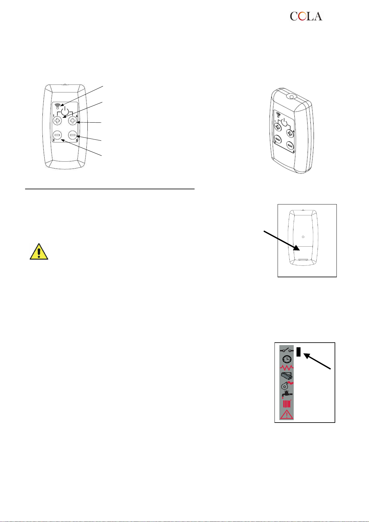
4.7 Telecomando
Il telecomando funziona con le impostazioni settate nel pannello di comando e consente l’accensione-spegnimento
della stufa , la regolazione della potenza e la temperatura che si desidera avere .
Essendo un dispositivo che trasmette tramite un diodo ad infrarosso è necessario il puntamento verso l’unità
ricevente inserita nel pannello di comando .
Il telecomando consente le seguenti operazioni :
: Led acceso con la pressione di qualsiasi tasto
Tasto P1+P6 : Accensione-spegnimento stufa
Tasto P1: Aumento temperatura ambiente
Tasto P6: Aumento livello di potenza
Tasto P5: Diminuzione livello di potenza
Tasto P2: Diminuzione temperatura ambiente
Sostituzione batteria
Il telecomando viene fornito senza la batterie di alimentazione , esso funziona
con una batteria posta nella parte inferiore del dispositivo e per il suo inserimento ed
eventuale sostituzione è necessario procedere nel modo seguente :
-
Aprire il coperchio posto nella parte posteriore del telecomando ;
- Sostituire la batteria modello p23ga da 12V nella sede rispettando la polarità ;
- Chiudere il telecomando ;
- Controllare il regolare funzionamento .
- Tenere il telecomando lontano da fonti di calore dirette e dall’acqua .
- La batteria del telecomando deve essere sostituita e smaltita in modo
sicuro rispettando le norme locali ;
4.8 Termostato - cronotermostato esterno
L’apparecchio di serie controlla la temperatura ambiente tramite un proprio termostato
digitale che ha la funzione di rilevare la temperatura attraverso una sonda e di
abbassare la potenza quando viene raggiunta la temperatura impostata .
Se si desidera utilizzare un termostato esterno rivolgersi ad un tecnico autorizzato e
seguire le seguenti indicazioni :
- spegnere l’apparecchio agendo sull’interruttore generale posto sul lato posteriore e
staccare il cavo dall’alimentazione ;
- smontare la pannellatura laterale per accedere al controllo elettronico ;
- con riferimento allo schema elettrico , collegare i due cavi del termostato sui relativi
morsetti TERM della scheda ;
- rimontare il tutto e verificare il corretto funzionamento .
Di seguito viene riportata la procedura di impostazione :
- termostato esterno : impostare un SET temperatura pari a 7°C ;
- cronotermostato esterno : impostare un SET temperatura pari a 7°C e disabilitare
dal menu 03-01 le funzionalità crono .
Per ognuna delle impostazioni tutte le funzioni del menu non cambiano e la
segnalazione del collegamento avviene con l’accensione del led a segmento sullo
barra degli stati nel display .
4.9 Periodo di inattività
( fine stagione )
Se la stufa non viene utilizzata per lunghi periodi, e/o a fine di ogni stagione è consigliato operare come segue :
- togliere completamente il pellet dal serbatoio ;
- scollegare l’alimentazione elettrica ;
- pulire accuratamente e, se necessario, sostituire eventuali parti danneggiate da parte di personale qualificato ;
- proteggere la stufa dalla polvere con idonea copertura ;
- sistemare in un luogo asciutto sicuro e riparato da agenti atmosferici .
TERMO-POWER
29
Page 30
r la
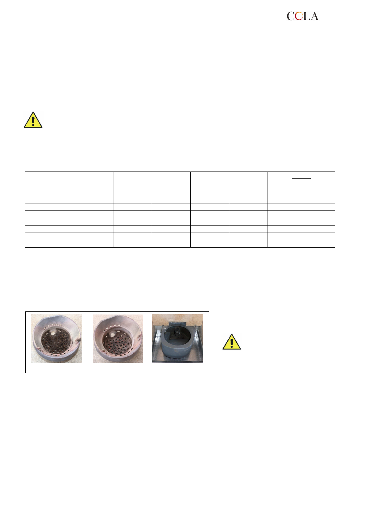
circolazione dell’aria sulla superficie interna del vetro . E’ importante mantenere pulite tali fessure da eventuali
depositi di cenere e polvere. Eseguire quindi periodicamente una pulizia lungo tutto il contorno del vetro, lato interno
Il braciere deve appoggiare sul
porta braciere e precisamente su
tutta la fascia anulare senza
5 PULIZIA DELLA STUFA
E’ importante procedere alla pulizia della stufa per evitare : annerimento del vetro, cattiva combustione, deposito di
cenere ed incombusti nel braciere nonché minore efficienza termica .
La stufa deve funzionare solo ed esclusivamente con porta fuoco sempre chiusa.
Le guarnizioni porta fuoco devono essere controllate periodicamente per evitare infiltrazioni d’aria ; infatti la camera
di combustione ed il condotto di scarico pellet lavorano in depressione mentre con lo scarico fumi in leggera
pressione .
Le operazioni di pulizia ordinarie vengono normalmente effettuate dal cliente seguendo le indicazioni del manuale
mentre le manutenzioni straordinarie , almeno 1 all’anno , devono essere svolte dal Centro Assistenza Tecnico
autorizzato .
- Le operazioni di pulizia di tutte le parti vanno eseguite a stufa completamente fredda ed
elettricamente scollegata ;
- Smaltire i rifiuti della pulizia secondo le norme locali vigenti ;
- E’ vietato mettere in funzione la stufa priva dei rivestimenti esterni ;
- Evitare la formazione di fumo ed incombusti in fase di accensione e/o durante il normale
Di seguito vengono riassunti gli interventi di controllo e/o manutenzione utili per il corretto utilizzo e funzionamento
della stufa .
Braciere
Vano cenere-cassetto
Vetro porta
Fascio tubiero termocamera
Collettore – estrattore fumi
Guarnizione porta - vetro
Canna – raccordo fumario
5.1 Pulizia braciere
Togliere il braciere, ed asportare i residui di cenere che si sono depositati nella camera di combustione e nel porta
braciere . A tale scopo può essere utilizzato un idoneo aspiratore. Questa operazione dovrà essere eseguita
quotidianamente soprattutto in presenza di accumulo di materiale incombusto per assicurare una perfetta
condizione di combustione in quanto i fori del braciere permettono il passaggio dell’aria di combustione .
funzionamento.
Parti / Periodo
Tipologia della pulizia
1 giorno
pulizia
ordinaria
2-3 giorni
pulizia
ordinaria
1 mese
pulizia
ordinaria
2 - 3 mesi
pulizia
ordinaria
pulizia straordinaria :
effettuata dal Centro
■
■
■
■ ■
■ ■
■
■
1 anno
Assistenza Tecnico
presentare luci di passaggio aria.
Braciere sporco Braciere pulito Porta Braciere pulito
5.2 Pulizia contenitore cenere
Direttamente sotto il braciere - porta braciere è collocato il contenitore cenere . Per procedere alla sua pulizia è
necessario aprire la porta fuoco ed aspirare con un idoneo aspiratore la cenere presente al suo interno ed eventuali
residui di combustione.
Dopo la pulizia, è necessario chiudere lo sportello .La pulizia del contenitore cenere può essere eseguita ogni 2-3
giorni in funzione dell’utilizzo della stufa.
5.3 Pulizia del vetro
La pulizia del vetro può essere effettuata con un panno umido utilizzando detergenti specifici non abrasivi .
Tra vetro, ferma vetri e porta fuoco sulla parte inferiore e superiore sono state realizzate apposite fessure pe
ed esterno alla porta .
TERMO-POWER
30
Page 31
bassa di f
unzionamento termostufa .
5.4 Pulizia estrattore fumi e della camera di combustione
Almeno una volta all’anno si deve procedere alla pulizia della camera di combustione, rimovendo tutti i residui di
combustione dai tubi fumi interni, e dal percorso fumi. Per eseguire tale operazione è necessario rimuovere il
coperchio superiore della stufa , il coperchio della termocamera e lo sportello inferiore d’ispezione svitando le
necessarie viti di fissaggio e procedere quindi alla pulizia dei turbo latori e dei tubi fumo interni alla camera.
Inoltre è importante pulire l’estrattore fumi collocato sotto il collettore inferiore fumi che si accede attraverso il vano
dello sportello d’ispezione
Ogni 3-4 mesi pulire le pareti interne della camera di combustione con opportune attrezzature (pennelli) ed
eventualmente sostituire la parete in vermiculite in quanto considerata materiale di usura.
La stufa ogni 1800 ore di funzionamento segnala , tramite un messaggio ‘ SCADENZA SERVICE ’ , la richiesta di
manutenzione straordinaria ( non in garanzia ) da parte di personale qualificato , il quale provvede ad una pulizia
completa e al ripristino del messaggio .
Eventuali urti o forzature possono danneggiare l’estrattore fumi rendendolo rumoroso durante
il funzionamento pertanto si consiglia di far eseguire tale operazione da personale qualificato .
5.5 Pulizia debimetro
All’interno del tubo di aspirazione è installato un debimetro ( misuratore del flusso d’aria comburente ) , il quale
periodicamente , ogni 3-4 mesi necessità di una pulizia interna con opportune attrezzature ( soffio d’aria compressa
o idonei pennelli ) .
5.6 Pulizia delle ceramiche
Le ceramiche sono di fabbricazione artigianale e come tali possono presentare delle piccole imperfezioni superficiali
sia come micro puntinature sia come disomogeneità cromatiche . Per la pulizia delle ceramiche si consiglia di usare
un panno morbido ed asciutto ; l’utilizzo di eventuali detergenti potrebbe evidenziare le eventuali imperfezioni .
5.7 Pulizia raccordo fumi – canna fumaria
Il raccordo fumi deve essere pulito minimo una volta all’anno o quando se ne presenti la necessità .
L’operazione di pulizia prevede l’aspirazione e la rimozione dei residui su tutti i tratti verticali e orizzontali nonché le
curve dall’apparecchio alla canna fumaria .
E consigliato pulire annualmente anche la canna fumaria per avere la garanzia di una corretta e sicura evacuazione
dei fumi .
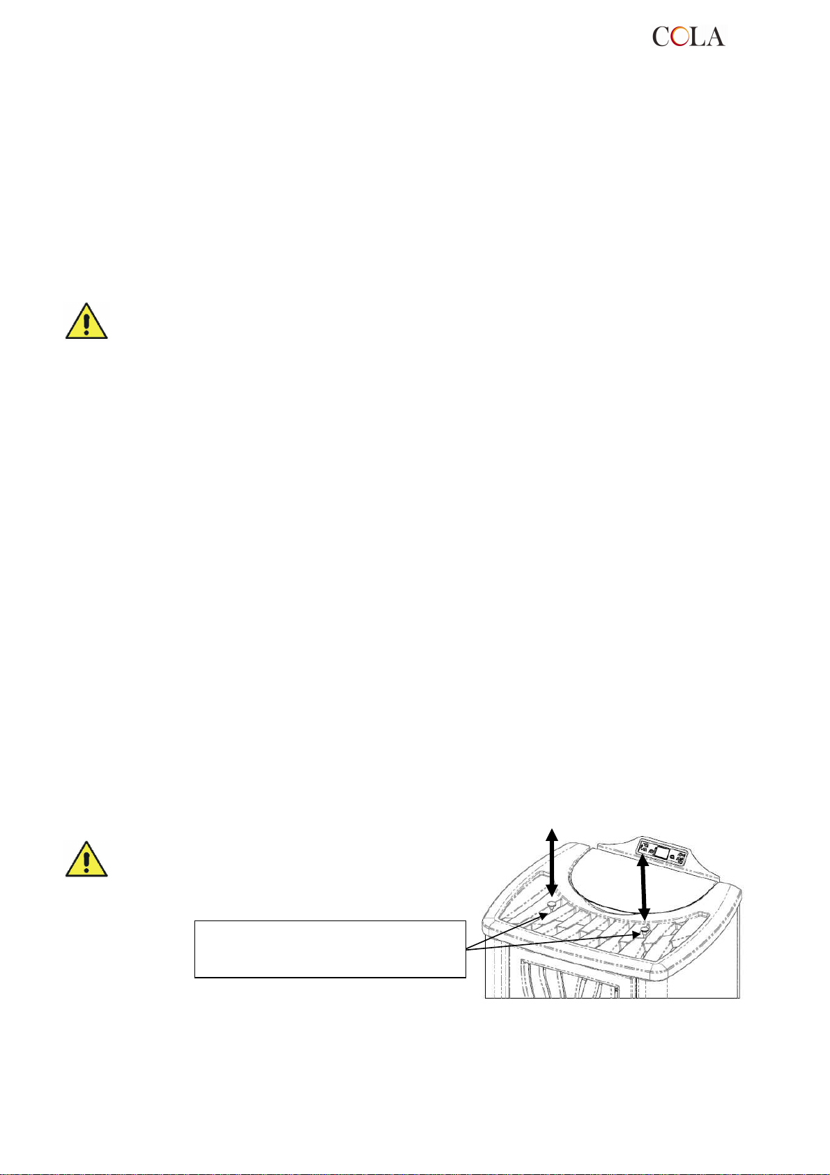
5.8 Pulizia scambiatori con il dispositivo scuoti-turbolatori
La pulizia dei tubi passaggio fumi interni alla termo camera va
eseguita almeno una volta al giorno agendo ripetutamente sui
due pomelli con movimento dal basso verso l’alto e viceversa .
Eseguire l’operazione a stufa spenta e fredda .
Pomelli di comando DX – SX del
dispositivo scuoti-turbolatori in posizione
TERMO-POWER
31
Page 32
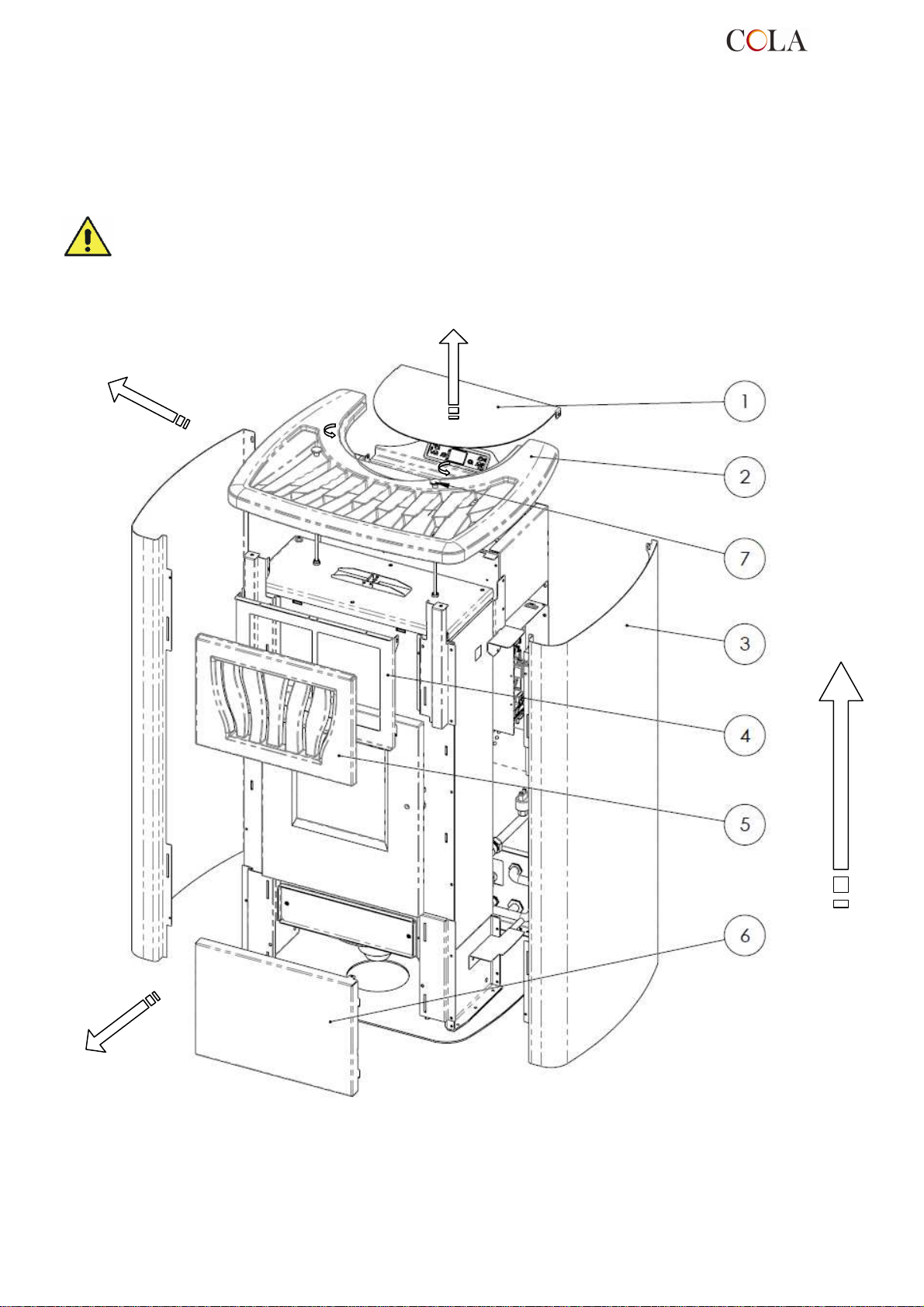
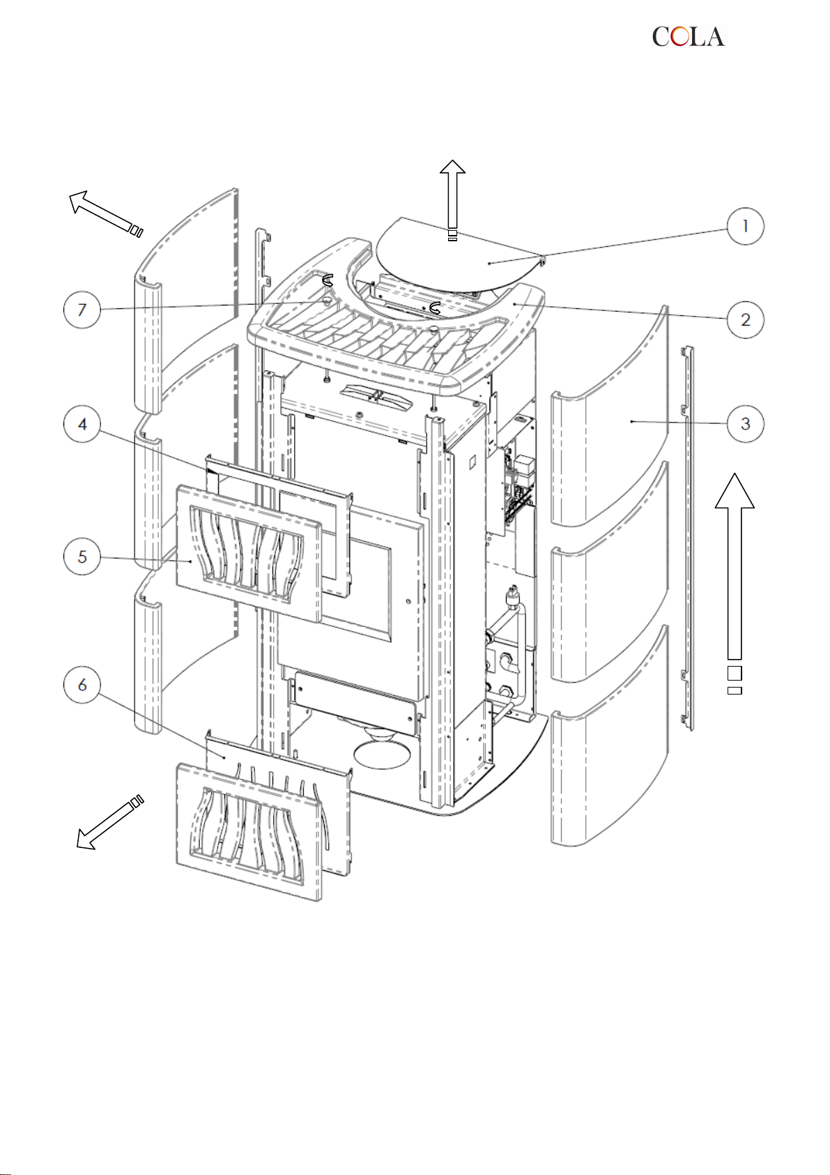
Legenda :
6 MANUTENZIONE
6.1 Premessa
Gli interventi sui componenti interni della stufa devono essere effettuati da personale qualificato, rivolgendosi al
centro assistenza autorizzato più vicino.
Prima di ogni intervento accertarsi che sia disinserita la spina dell’alimentazione elettrica e la stufa sia
completamente fredda.
6.2 Smontaggio rivestimento TERMO POWER
1- Sportello pellet
2- Coperchio in maiolica
3- Pannello laterale
4- Supporto frontalino superiore
5- Frontalino superiore in maiolica
6- Frontalino inferiore
7- Prolunghe con pomello per turbolatori
TERMO-POWER
32
Page 33
Legenda :
6.3 Smontaggio rivestimento TERMO POWER LUX
1-Sportello pellet
2-Coperchio in maiolica
3-Maiolica laterale
4-Supporto frontalino superiore
5-Frontalini superiore-inferiore in maiolica
6-Supporto frontalino inferiore
7-Prolunghe con pomello per turbolatori
TERMO-POWER
33
Page 34
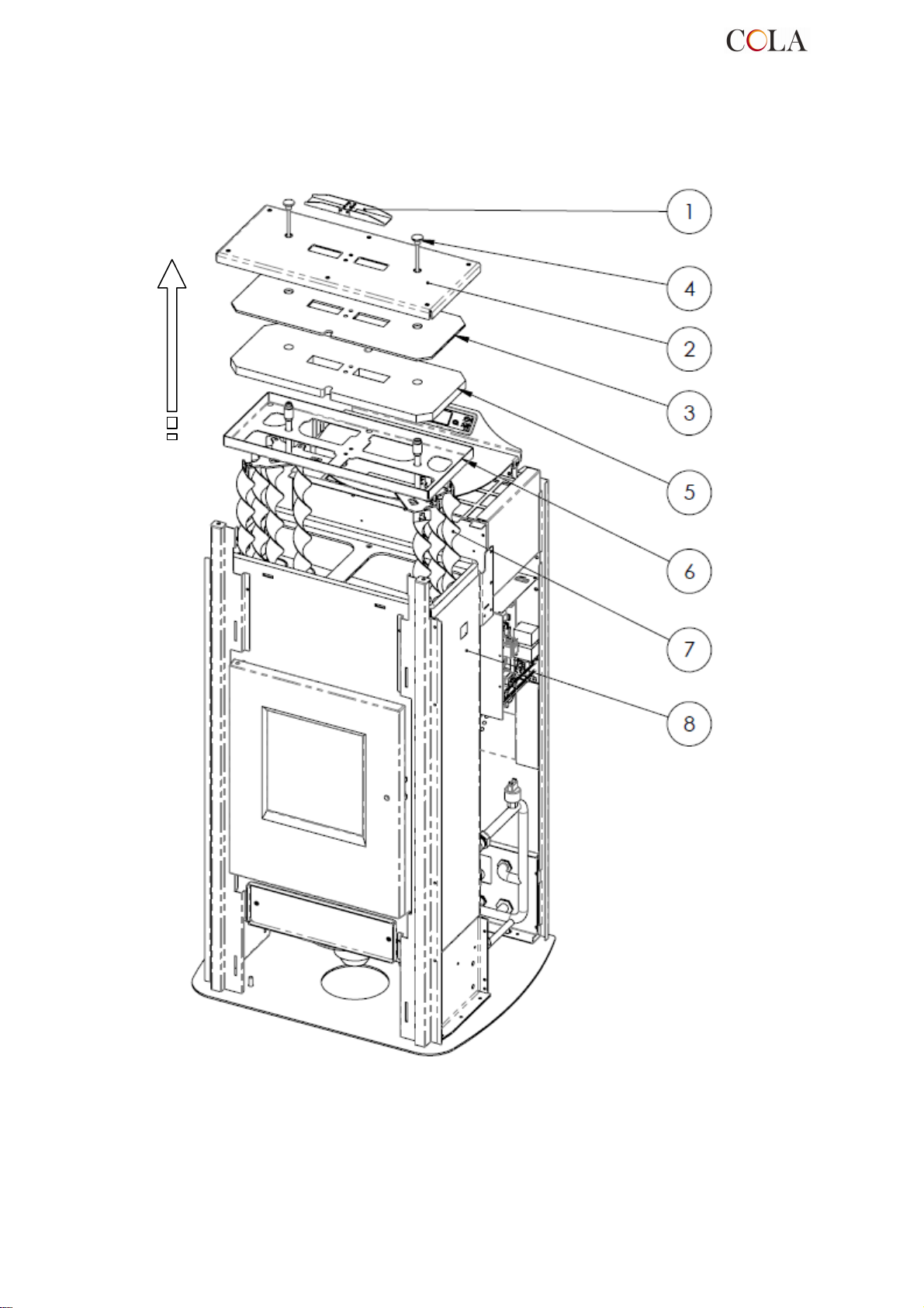
Vista esplosa della camera di combustione e delle parti collegate rif.
Legenda :
6.4 Componenti interni della stufa
TERMO-POWER
34
1-Valvola di sicurezza
2-Coperchio termocamera
3-Protezione in isolcart
4-Pomello per scuotimento turbolatori
5-Protezione in vermiculite
6-Telaio inferiore coperchio
7-Turbolatori
8-Termocamera
Termo-stufa mod.TERMO-POWER
Page 35
Legenda:
Legenda:
Legenda:
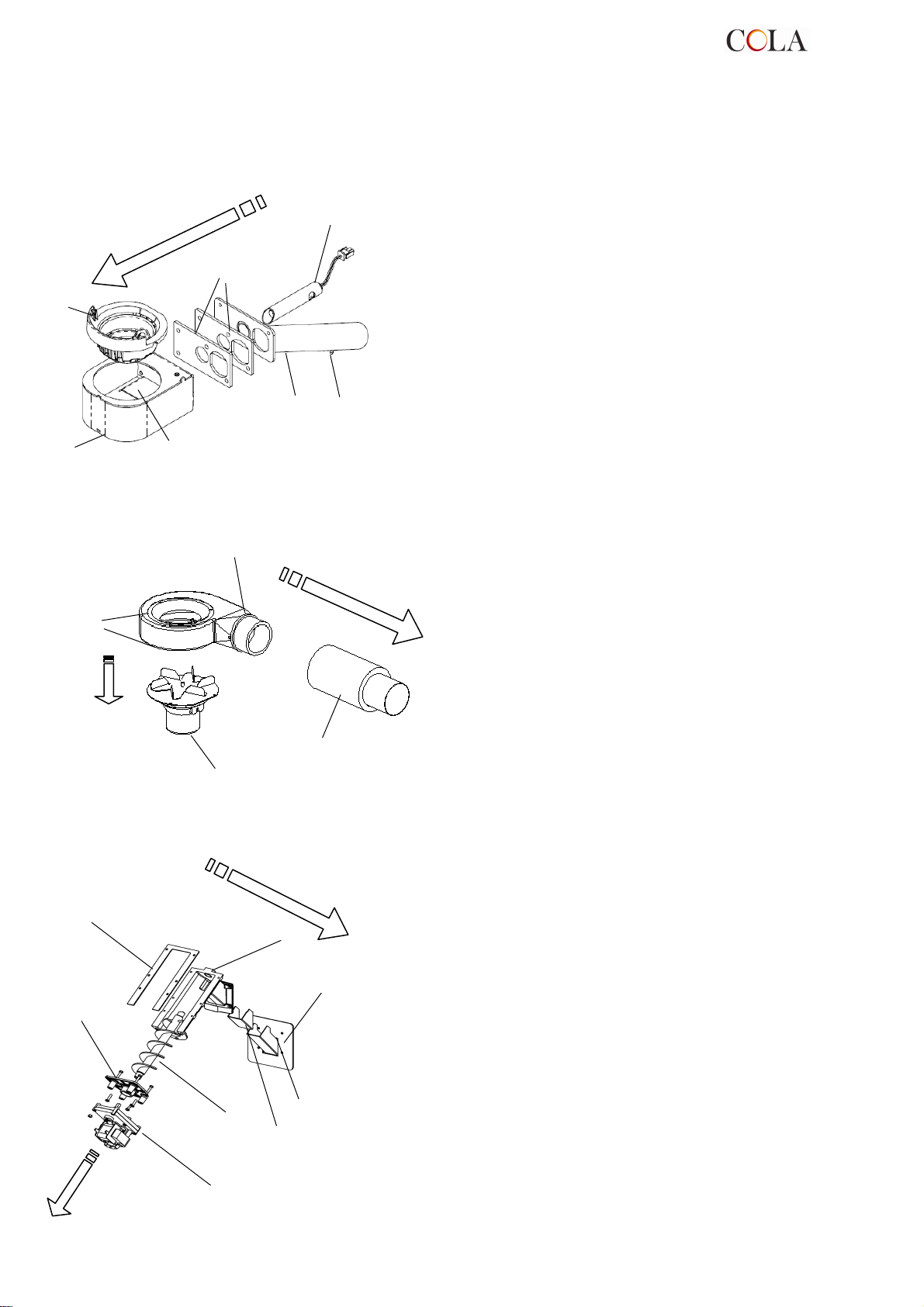
Rappresentazioni esplose di:
1- Gruppo braciere
2- Gruppo estrattore fumi
3- Gruppo coclea
6
1
2
3
5
1-Braciere
2-Porta braciere saldato
3-Deviatore fumi interno
4-Gruppo saldato tubo aspirazione
aria comburente
4
7
5-Resistenza elettrica
6- Guarnizioni
7- Venturimetro
1
2
4
3
1
8
7
2
1-Voluta estrattore fumi
2-Guarnizione termica
3-Motore estrattore fumi
4-Tubo espulsione fumi
1-Guarnizione serbatoio - convogliatore
2-Flangia ferma motoriduttore
3-Motoriduttore
4-Coclea
5-Guarnizione per scivolo
6-Scivolo caduta pellet
7-Guarnizione camera-convogliatore
8-Convogliatore pellet
4
3
6
5
TERMO-POWER
35
Page 36
Legenda :
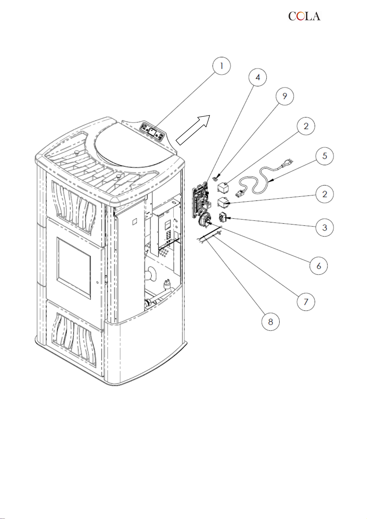
6.5 Componenti elettrici
1-Pannello comandi mod.F047
2-Termostati di sicurezza
3-Interuttore ON-OFF con fusibili
4-Scheda elettronica
5-Cavo alimentazione
6-Vacuostato
7-Sonda fumi
8-Sonda ambiente
9-Connessione seriale
TERMO-POWER
36
Page 37
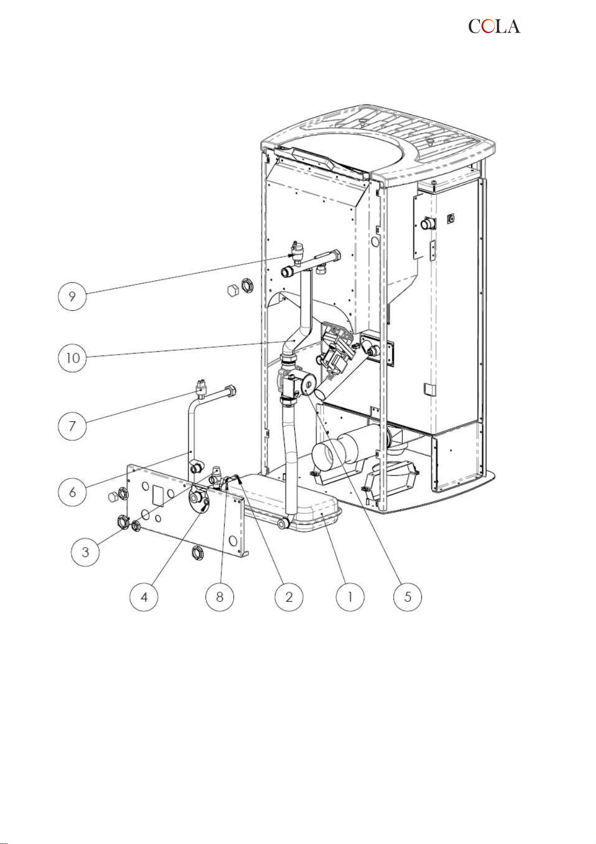
Legenda :
6.6 Componenti idraulici
TERMO-POWER
1- Vaso espansione a membrana
2- Rubinetto scarico impianto
3- Valvola di sicurezza
4- Attacco carico impianto
5- Circolatore
6- Tubo di ritorno
7- Trasduttore di pressione
8- Attacco Vaso di espansione
9- Valvola di sfiato aria
10- Tubo mandata
37
Page 38

7 RICERCA GUASTI
7.1 Gestione degli allarmi
La presenza di un allarme si identifica con l’emissione di un segnale acustico (se attivato) e con un messaggio
presente sul pannello di controllo.
In caso di allarme spegnere la stufa, risolvere la causa che lo ha provocato e riavviare la stufa secondo la normale
procedura illustrata nel presente manuale.
Ogni condizione di allarme causa l’immediato spegnimento della stufa .
Sotto sono elencati gli allarmi che possono comparire sul pannello di controllo con cause e rimedi :
ALLARMI - MESSAGGI
Segnalazione Anomalia Cause possibili Rimedi
-Portare la stufa in OFF
premendo il pulsante P4 e
AL 1
BLACK OUT
AL 2
SONDA
FUMI
AL 3
HOT FUMI
-La stufa non si avvia .
-Avviene nel caso di guasto
della sonda di rilevamento
della temperatura dei fumi .
-Viene attivata la procedura di
spegnimento .
-Avviene nel caso cui la sonda
fumi rilevi una temperatura dei
fumi superiore a 280°C.
-Viene attivata la procedura di
spegnimento .
-Manca l’alimentazione
elettrica durante la fase di
accensione .
-La sonda è guasta
-La sonda è scollegata dalla
scheda .
-Il ventilatore tangenziale è
difettoso .
-Manca l’alimentazione al
ventilatore tangenziale .
-Eccessivo carico pellet .
ripetere la procedura di
accensione .
-Altre operazioni di ripristino
devono essere condotte da
un centro di assistenza .
-Le operazioni di ripristino
devono essere condotto da un
centro di assistenza .
-Regolare l’afflusso del pellet.
-Altre operazioni di ripristino
devono essere condotte da un
centro di assistenza .
AL 4
ASPIRAT-
GUASTO
AL 5
MANCATA
ACCENS
AL 6
MANCANO
PELLET
AL 7
SICUREZ
TERMICA
-Avviene quando il ventilatore
di aspirazione fumi è guasto.
-Viene attivata la procedura di
spegnimento .
-In fase di accensione non
parte la fiamma.
-Viene attivata la procedura di
spegnimento .
- Non viene alimentato di
pellet il braciere.
-Avviene nel caso di intervento
del termostato di sicurezza
della temperatura canale
coclea o della temperatura
acqua della termo camera .
-Il sistema viene arrestato.
-Il ventilatore fumi è bloccato.
-Il sensore controllo velocità è
guasto .
-Manca l’alimentazione
elettrica al ventilatore fumi .
-Il serbatoio del pellet è vuoto.
-La resistenza elettrica è
difettosa, sporca o fuori dalla
corretta posizione .
-Taratura carico pellet non
corretta .
-Il serbatoio del pellet è vuoto.
-Il motoriduttore di carico pellet
deve assestarsi .
-Il motoriduttore non carica
pellet .
-Il termostato di sicurezza ha
rilevato una temperatura
superiore alla soglia di
taratura per un
surriscaldamento della parte
inferiore del serbatoio o
dell’acqua della termo camera
, bloccando il funzionamento
del motoriduttore .
-Le operazioni di ripristino
devono essere condotte da
un centro di assistenza .
-Verificare la presenza di
pellet nel serbatoio .
-Verificare le procedure di
accensione .
-Altre operazioni di ripristino
devono essere condotto da
un centro di assistenza .
-Verificare la presenza di
pellet nel serbatoio .
-Regolare l’aflusso del pellet
-Altre operazioni di ripristino
devono essere condotto da
un centro di assistenza .
-Verificare la causa dello
eccessivo surriscaldamento.
-Sbloccare il termostato
interessato al
surriscaldamento agendo sul
pulsante di ripristino .
TERMO-POWER
38
Page 39

centro di assistenza .
La ditta si
riserva di apportare in qualsiasi momento, senza preavviso alcuno, eventuali modifiche tecniche od estetiche ai prodotti.
I disegni, le misure, gli schemi ed ogni altra configurazione, sono qui riportati solo a scopo esemplificativo.
Segnalazione Anomalia Cause possibili Rimedi
-Verificare la pulizia del
condotto fumario e della
camera di combustione .
-Verificare la chiusura
ermetica della porta .
-Verificare la chiusura delle
valvole antiscoppio .
-Altre operazioni di ripristino
devono essere condotte da un
-Verificare la pulizia del
condotto fumario e della
camera di combustione .
-Verificare la chiusura
ermetica della porta .
-Verificare la chiusura delle
valvole antiscoppio .
-Altre operazioni di ripristino
devono essere condotte da un
centro di assistenza .
-Verificare la causa del
problema ripristinando la
pressione del circuito e
riportando al valore di normale
funzionamento .
-Le operazioni di ripristino
devono essere condotte da un
centro di assistenza .
-Le operazioni di ripristino
devono essere condotto da un
centro di assistenza .
-Verificare la causa del
problema ripristinando la
temperatura elevata e
riportando il valore al normale
funzionamento .
-Lo sblocco dell’allarme sarà
possibile solamente a
spegnimento ultimato .
AL 8
MANCA
DEPRESS
AL 9
TIRAGGIO
INSUFF
AL E
PRESS
ACQUA
AL b
ERRORE
TRIAC COC
AL c
SONDA
ACQUA
AL d
HOT
ACQUA
ATTESA
RAFFRED
-In fase di lavoro la stufa
rileva una pressione inferiore
alla soglia di taratura del
vacuostato.
-Il sistema viene arrestato.
-Compare quando il flusso
d’aria comburente è sotto
una certa soglia .
-Avviene quando la
pressione dell’acqua non
rientra nei valori di corretto
funzionamento.
-Il sistema viene arrestato.
-Avviene quando il
motoriduttore funziona in
continuo e più di 60 sec.
-Il sistema viene arrestato.
-Avviene di guasto della
sonda di rilevamento della T
acqua visualizzando T H2O
= 0 °C - Viene attivata la
procedura di spegnimento .
-Avviene quando la
temperatura dell’acqua ha
superato i limiti prestabiliti .
-Il sistema viene arrestato.
-Avviene riaccendendo
subito dopo aver spento la
stufa .
-La camera di combustione è
sporca .
-Il condotto fumi è ostruito.
-La porta fuoco non è chiusa.
-Le valvole antiscoppio sono
aperte-inceppate .
-Il vacuostato è difettoso .
-La camera di combustione è
sporca .
-Il condotto fumi è ostruito.
-La porta fuoco non è chiusa.
-Le valvole antiscoppio sono
aperte-inceppate .
-Il debimetro è difettoso .
- Avviene quando il trasduttore
di pressione inserito nel
circuito idraulico rileva una
pressione inferiore o superiore
ai limiti prestabiliti .
-Il controllo rileva che il relè
comando motoriduttore è in
avaria ( contatti incollati) .
-La sonda è guasta
-La sonda è scollegata dalla
scheda .
- Avviene quando la sonda di
temperatura inserita nella
termocamera rileva un valore
superiore ai 92 °C.
-Tentativo di sblocco in fase di
spegnimento con la stufa
calda in fase diraffreddamento
-Il controllo non rileva la
GUASTO
DEBIMET
PERICOLO
GELO
SCADENZA
SERVICE
TERMO-POWER
-Avviene quando il debimetro
viene scollegato .
-Avviene quando la
temperatura acqua scende
sotto una certa temperatura
.
-Avviene quando la stufa ha
superato le 1800 ore di
funzionamento dal
precedente intervento di
manutenzione .
quantità d’aria comburente
ma non spegne la stufa ,
esclude solamente le funzioni
del debimetro .
-Il controllo della stufa rileva la
temperatura acqua sotto i 6°C
e avvisa tramite il display .
-Avviso di manutenzione
straordinaria .
39
- Le operazioni di ripristino
devono essere condotte da
un centro di assistenza .
- La pompa si accende per
movimentare l’acqua
all’interno del circuito di
riscaldamento .
- Monitorare la temperatura
dell’acqua affinchè non
scenda sotto i 0°C .
- Le operazioni di pulizia -
manutenzione straordinaria e
di ripristino devono essere
condotte da un centro di
assistenza autorizzato.
Page 40
8 ALLEGATI
INFORMAZIONI MARCATURA CE
COLA
2012
EN 14785 : 2006
Distanza minima di sicurezza da materiali infiammabili
Dietro - lato dx/sx - pavimento
Apparecchi per il riscaldamento domestico a pellet di legno
Ref. TERMO POWER – TERMO POWER LUX
Emissioni di CO al 13% O2 nei prodotti di combustione :
Emissioni polveri al 13% O2 nei prodotti di combustione :
Massima pressione idrica di esercizio : 2 bar
Temperatura gas di scarico :
Potenza termica nominale e ridotta
Rendimento
Tipi di combustibile
Potenza elettrica
Tensione nominale
Frequenza nominale
: 200 – 200 - 0 mm
Pnom : 0,005 %
Prid : 0,01 %
Pnom : 10.7 mg/m3
P.nom. 119.3 °C
P.rid. 58.9 °C
Pnom : total 23.5 kW
water heat 20.1 kW
space heat 3.4 kW
Prid : total 7.1 kW
water heat 5.6 kW
space heat 1.44 kW
Pnom : 93.6 %
:
:
:
:
:
Prid : 95.2 %
Pellet di legno
420 W – 140 W
230 V
50 Hz
TERMO-POWER
40
Page 41

1. GENERAL INFO
RMATION
1.1. Introduction
1.2. Using the manual
1.3. Safety rules
1.4. Technical description
1.5. Permissible use and fuel
1.6. Accessories supplied
1.7. Reference standards
1.8. Dataplate
1.9. Stove decommissioning
1.10. Instructions for requesting assistance
and replacement parts
2. TRANSPORT AND INSTALLATION
2.1. Packing, handling, shipment and
transport
2.2. Place of installation, positioning and fire-
prevention safety
2.3. Air inlet
2.4. Fume exhaust
2.4.1. Types of installation
2.5. Brazier and turbulator position check
2.6. Electrical connection
2.7. Wiring diagram
2.8. Wiring diagram for zone system
2.9. Plumbing connections
2.10. Emergency
3. STOVE SAFETY
3.1. Safety distance from flammable
materials.
3.2. Fume exhaust safety
3.3. Combustion chamber overpressure safety
3.4. Overheating - pellet hopper temperature
safety thermostat
3.5. Safety against flare-back in the pellet
chute
3.6. Overcurrent electrical protection device
3.7. Power failure safety
3.8. Water circuit overpressure safety
3.9. Fume fan failure
4. STOVE USE
4.1. Introduction
4.2. Description of control panel
4.3. Lighting
4.3.1 Check before lighting
4.3.2 Startup stage
4.4. Work stage
4.4.1 Modifying the room temperature setting
4.4.2 Modifying the water temperature setting
4.4.3 Restart from STAND-BY
4.4.4 Cleaning the brazier
4.4.5 Water heater with heat exchanger quickly
4.4.6 Water heater with storage tank
4.4.7 System with puffer / heat storage
4.5. Shutting down
5 STOVE CLEANING
6 MAINTENANCE
7 TROUBLESHOOTING
8 ENCLOSURES
4.6 Menu
4.6.1 menu 01 – adjust fans
4.6.2 menu 02 – set clock
4.6.3 menu 03 – enable chrono
4.6.4 menu 04 – select language
4.6.5 menu 05 – standby mode
4.6.6 menu 06 – buzzer
4.6.7 menu 07 – initial loading
4.6.8 menu 08 – stove status
4.6.9 menu 09 – settings by
technician
4.7 Remote control
4.7.1 replacing the battery
4.8 Thermostat – external
chronothermostat
4.9 Idle period (end of season)
5.1 Cleaning the brazier
5.2 Cleaning the ash pan
5.3 Cleaning the glass
5.4 Cleaning the fume extractor and
combustion chamber
5.5 Cleaning the air flow meter
5.6 Cleaning the ceramic surfaces
(ceramic models)
5.7 Cleaning the flue - flue connection
5.8 Cleaning the exchanger with
turbulator-shaker device
6.1 Introduction
6.2 Removing the cladding T-POWER
6.3 Removing the cladding T-POWER
LUX
6.4 Stove internal parts
6.5 Electrical components
6.6 Plumbing components
7.1 Alarm management
8.1 CE marking information
TERMO-POWER
41
Page 42
1 GENERAL INFORMATION
1.1 Introduction
Dear Customer,
First of all we wish to thank you for the trust placed in us by purchasing one of our products. Please read and
carefully follow the advice given in this installation, use and maintenance manual in order make best use of the
product.
1.2 Using the manual
The Manufacturer reserves the right to make technical or aesthetic changes to the products at any time without
notice.
Stove installation, use and maintenance operations must comply with the requirements given in this manual as well
as the European, National, Regional, Provincial and Municipal regulations.
The drawings, measurements, diagrams and any other configurations are given only by way of example.
This manual is an integral part of the product; make sure it always stays with the stove, even if sold, transferred to
another owner or installed in another place, so that it can be consulted at any time.
If lost or damaged, ask the Authorised Service Centre for a copy so that the stove always has its own manual.
This symbol indicates the presence of an important message; failure to pay attention to it can result in
serious damage to the stove and even injury
1.3 Safety rules.
- Read the use and maintenance manual before installing, lighting and servicing the stove.
- Have installation, the electrical connection, testing and maintenance carried out by a qualified and/or authorised
technician.
- Connect the stove to an approved flue by means of an inspectionable terminal; several units can be connected
only if allowed by the local regulations and by the flue inspection Body.
- Connect the stove to the suction system by means of a pipe or air inlet from outside.
- Connect the stove to an approved 230 V-50 Hz electrical socket.
- With the TERMO model, connect the unit to the heating system; under no circumstances can it be used without
the water connection and without water in the heating chamber.
- Make sure the electrical system and the sockets are suitable for the maximum absorption of the unit, specified
on the label and in this manual.
- The stove must be unplugged and cold before carrying out any maintenance.
- Do not use flammable liquids or substances to light the stove or rekindle the flame: when the stove is lit, pellet
ignition is automatic.
- The pellet stove must only be fed with wood pellets having the
characteristics described in this manual.
- The stove must not be used as an incinerator.
- Never block the combustion air inlet and fume outlet openings.
- Do not handle easily flammable or explosive substances near the stove while
it is operating.
- Do not remove the pellet hopper protection grille.
- Do not operate the stove with the fire door open and/or the glass damaged or broken.
- During operation the intense heat generated by combustion of the pellets makes the external surfaces of the
stove very hot, and in particular the fire door, handle and flue pipe. Therefore avoid contact with these parts
without suitable protection.
- Keep objects that are flammable and/or not heat resistant at a suitably safe distance.
- Clean the brazier regularly every time the stove is lit or whenever reloading pellets.
- Avoid the creation of smoke and unburnt products during lighting and/or normal operation; an excessive
accumulation of unburnt pellets in the brazier must be eliminated manually before relighting the stove.
- Have the pipe and smoke baffles inside the combustion chamber cleaned regularly by qualified personnel.
- Warn children and guests about the hazards described above.
- In case of operation problems, the stove can be relit only after eliminating the cause of the problem.
- Any tampering and/or unauthorised replacements with non-original parts of the stove can create a risk for the
user's safety and relieves the manufacturer of any civil or penal liability.
- Only use original replacement parts recommended by the manufacturer.
Pay special attention to “words in bold face"
The manufacturer declines any liability for problems, damage or accidents caused by failure to follow or
apply the instructions contained in this manual.
TERMO-POWER
42
Page 43

1.4 Technical description
The stove works exclusively on pellets and enables easy installation with the heating system. The stove's automatic
control systems guarantee optimum heat output and complete combustion; there are also safety systems to
guarantee safe operation for the stove parts and for the user.
When correctly installed, the unit works in any outside climatic conditions, and in any case in critical conditions
(strong wind, frost, etc.) the safety systems can cut in, shutting down the stove.
Structure steel and cast iron
Combustion chamber steel
Heat output nominal - reduced
Heat output in H2O production Nominal outputReduced output
Heat output in air heating Nominal output – Reduced
output
Hourly consumption Nominal output- Reduced
output
Efficiency Nominal output- Reduced output
Fume outlet temperature Nominal output- Reduced
output
CO emissions at 13% O2
Flue gas flow
Dust emissions at 13% O2
Min. draught
Fume outlet pipe
Air inlet pipe
Electrical power supply
Electrical power input
Min. safety distance rear, right / left side
floor
P.nom 23.5 kW P red. 7.1 kW
P.nom 20.1 kW P red. 5.6 kW
P.nom 3.4 kW P red 1.44 kW
P.nom. 5.1 kg./h* P.
red
.1.52 kg./h.*
P.nom. 93.6 % P.red. 95.2 %
P.nom. 119.3 °C P.red. 58.9 °C
P.nom. 0.005 % P.red. 0.01 %
P.nom. 13.9 g/s P.red. 7.6 g/s
P.nom. 10.7 mg/m3
10 Pa
Ø 100 mm
Ø 50 mm
230V/50 Hz
420 W max. in lighting stage
140 W for normal operation
200 – 200 – 0 mm
Expansion tank capacity
Firebox capacity
Max. working pressure
Dimensions (mm)
Stove weight
Hopper capacity
Max. heatable volume
8 litri
Litri 23
2 bar
H x L x P = 1241 x 700 x 627 mm
212 kg - T-POWER
254 kg - T-POWER LUX
48 kg
530 m3 **
* Pellet consumption can vary according to the type of pellets used.
** Considering 35 W/h per m3. The building's energy requirement can vary according to the
insulation, type and climatic zone.
TERMO-POWER
43
Page 44
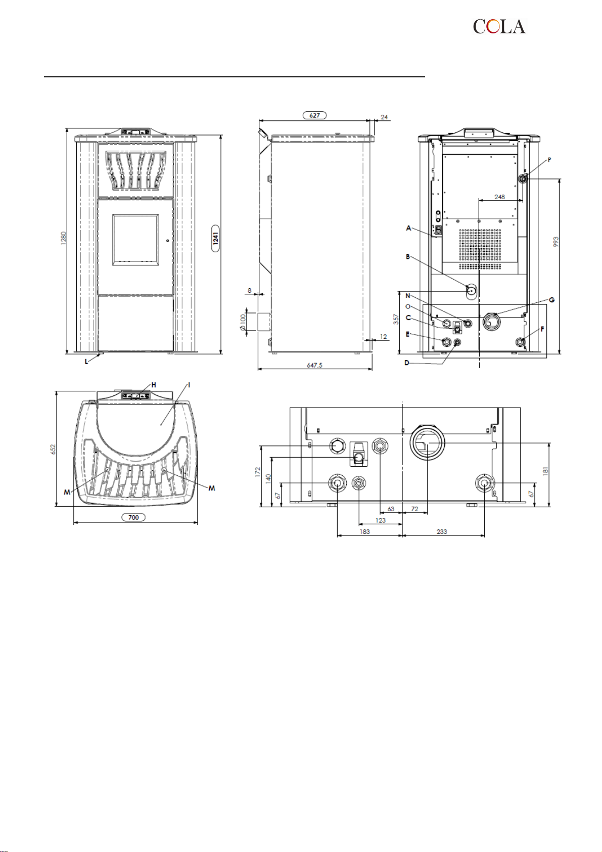
TERMO-POWER – TERMO-POWER LUX pellet heating stove dimensions
Key:
A - Power cable connection
B - Combustion air inlet
C - Overpressure water discharge (1/2" female - 3 bar)
D - Water system connection
E - System return (1" male )
F - System delivery (1" male )
G - Fume exhaust pipe connection D 100 mm
H - Control panel model F047
I - Pellet hopper door
L - Adjustable feet
M - Turbulator shaker handle
N - Optional DHW delivery ( 3/4" M – PUMP _ ½” M – EXCHANGER )
O - Optional DHW return ( 3/4" M – PUMP _ ½” M – EXCHANGER )
P - Supplementary delivery connection without pump (1" male)
Termo-POWER stove dimensions
TERMO-POWER
44
Page 45
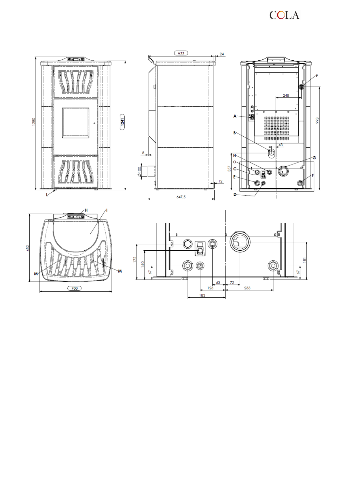
Key:
A - Power cable connection
B - Combustion air inlet
C - Overpressure water discharge (1/2" female - 3 bar)
D - Water system connection
E - System return (1" male)
F - System delivery (1" male)
G - Fume exhaust pipe connection D 100 mm
H - Control panel model F047
I - Pellet hopper door
L - Adjustable feet
M - Turbulator shaker handle
N - Optional DHW delivery ( 3/4" M – PUMP _ ½” M – EXCHANGER )
O - Optional DHW return ( 3/4" M – PUMP _ ½” M – EXCHANGER )
P - Supplementary delivery connection without pump (1" male)
Termo-POWER LUX stove dimensions
TERMO-POWER
45
Page 46
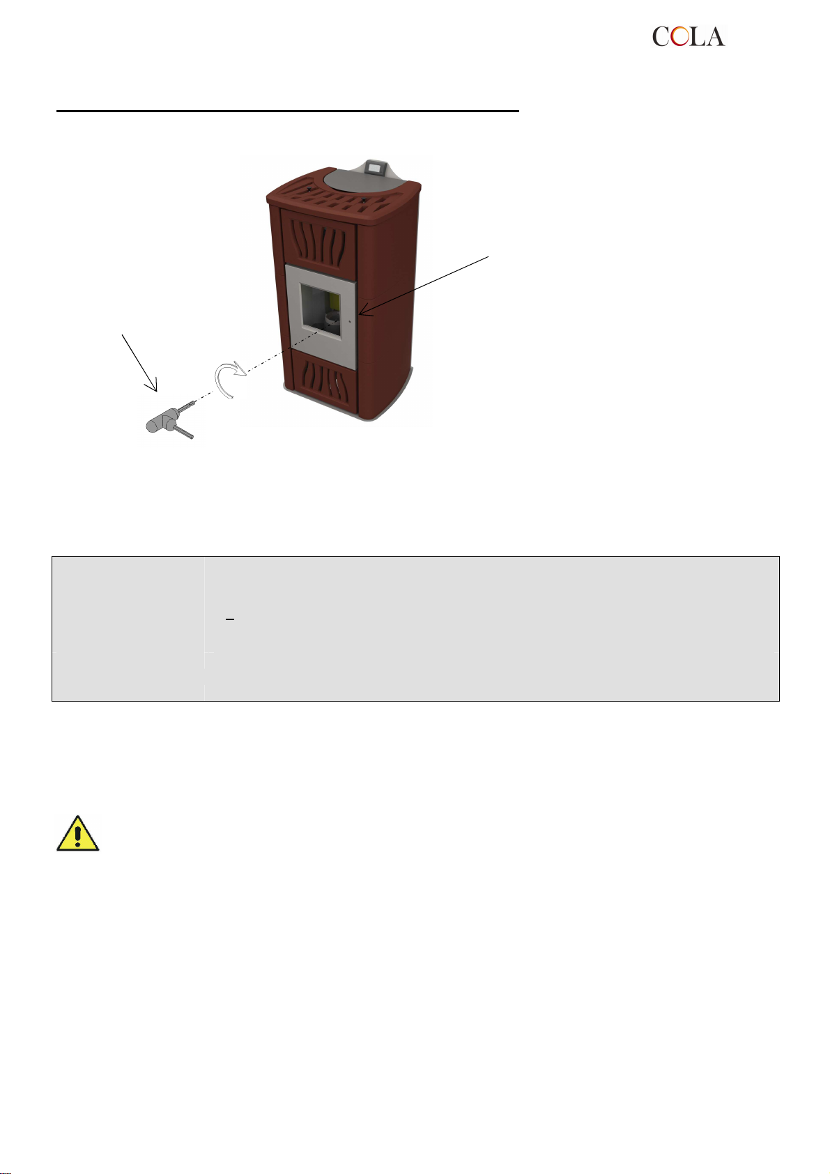
TERMO POWER pellet heating stove fire door opening - closing
To open the door, fit the handle
supplied and turn it clockwise
Fire door opening-closing
handle;
- Opening: anticlockwise
- Closing: clockwise
1.5 Permissible use and fuel
The pellet stoves work exclusively on pellets in different types of wood complying with Standard DIN plus 51731 or
UNI EN 14961-2 or Ö-Norm M 7135 or having the following characteristics:
Heat value: min. 4.8 kWh/kg (4180 kcal/kg)
Density: 680-720 kg
Moisture: max. 10% weight
Diameter: 6 +0.5 m
Ash percentage max. 1.5% weight
Length: min. 6 mm- max. 30 mm
Composition: 100% untreated wood from the wood industry or post consumer without added binding
substances or bark, complying with current regulations
Packing : in bags made from environmentally friendly or biodegradable material or paper
The pellet hopper is at the back of the stove. The door is located in the top part and pellet loading occurs manually
only with the stove off, making sure not to overfill.
The use of pellets with characteristics different from those tested by the technician during first lighting involves a new
setting of the stove pellet loading parameters; this operation is not covered by the warranty.
Store the pellets in a dry place.
For reasons of regular and efficient operation, pellets or other fuels cannot be manually loaded in
the brazier.
Do not load non-conforming fuels in the hopper.
Do not load foreign bodies such as containers, boxes, bags, metals, etc., in the hopper.
The use of poor quality and non-conforming pellets damages and compromises stove
operation, invalidating the warranty with the exclusion of liability of the manufacturer.
1.6 Accessories supplied
The supply includes:
Electrical power cable;
Installation, use and maintenance manual;
Opening - closing key;
Remote Control.
TERMO-POWER
46
Page 47
1.7 Reference standards
Standard UNI 10683:2005: Installation requirements for heat generators burning wood or other solid
biofuels;
Standard UNI EN14785:2006: Requirements for design, manufacture, construction, safety and performance,
instructions and marking, together with the relevant test methods for approval of
units burning pellets;
Standard CEI EN 60335-1: Safety of electrical appliances for domestic and similar use - part 1;
Standard CEI EN 60335-2-102: Safety of electrical appliances for domestic and similar use - part 2;
Standard CEI EN 55014-1: Electromagnetic resistance - Requirements for electrical appliances, electric tools
and similar electric equipment - Part 1: Emission of interference;
Standard CEI EN 55014-2: Electromagnetic resistance - Requirements for electrical appliances, electric tools
and similar electric equipment - Part 2: Immunity; Product family standard;
Standard CEI EN 61000-3-2: Limits for harmonic current emissions (Input current ≤16 A per phase);
Standard CEI EN 61000-3-3: Limitation of voltage fluctuations and flicker in low voltage supply systems for
equipment with nominal current ≤ 16 A;
Standard CEI EN 62233: Measuring methods for electromagnetic fields of electrical household appliances
and similar with reference to human exposure.
Standards DIN plus 51731 – UNI EN 14961-2 - Ö-Norm M 7135 : Standards regarding the specifications and
classification of pellets.
1.8 Dataplate
The dataplate is visible on the inside of the pellet hopper door or on the back of the stove. It gives the following data:
Model
►
Serial number
►
Type of fuel
►
Nominal and reduced heat output
►
Consumption at nominal output and reduced output
►
Flue gas temperature at nominal output and reduced output
►
Thermal efficiency
►
Power supply voltage
►
Electrical power input
►
Flue pipe size
►
Inlet pipe size
►
Min. draught
►
Stove external dimensions
►
Plumbing connection sizes
►
Safety distance from flammable materials
►
Weight
►
1.9 Stove decommissioning
When definitively deciding to not to use the stove any more, we recommend to disconnect the power supply and to
empty the pallet tank completely. In order to eliminate the stove, it is necessary to packaged it with a strong
packaging and then take contact with local organisation which follows the selling off operations respecting the local
rules. Otherwise we recommend to back the stove directly to the distributor when buying a similar new one.
On the basis of Article 13 by Legislative Decree n°1 51 of 25th July 2005 actuation of the European Directive
2002/96/CE of 23rd February 2003 on waste electrical and electronic equipment. It is connected to the policy
and action which aim to the prevention of waste electrical and electronic equipment,named RAEE, and in
addition, the reuse, recycling and other forms of recovery of such wastes so as to reduce the disposal of waste.
It also seeks to improve the environmental performance of all operators involved in the life cycle of electrical
and electronic equipment.
The picture of the bin crossed is labelled on the equipment, and it means that when the device is out of use it has to be
kept separated by other wastes.
1.10 Instructions for requesting assistance and replacement parts
To request any assistance and/or replacement parts contact your dealer, area importer or the nearest authorised
service centre, clearly specifying the following: stove model, serial number, date of purchase, list of replacement
parts, details of faults or malfunctioning.
All operations on components must be carried out by authorised and/or qualified personnel.
Make sure all electrical connections are disconnected and that the stove is cold before any work on it.
Only use original replacement parts.
2 TRANSPORT AND INSTALLATION
2.1 Packing, handling, shipment and transport
The stove complete with packing can be lifted using a lift truck, inserting the forks (of suitable length) in the special
spaces in the wooden pallet. Make sure the equipment used for lifting and transport can take the weight of the stove,
specified on the dataplate and in this manual.
Avoid taking the load in areas where it could be a danger if dropped.
Open the packing, remove the stove from the pallet and position it in the required place, making sure it complies with
that provided for, following the illustrations on the following pages.
Set the stove down on the floor carefully without bumping and position it in the required place. Make sure the floor
can take the weight of the stove, otherwise consult a specialised technician.
Disposal or recycling of the packing must be carried out by the end-user in compliance with the current local
regulations.
TERMO-POWER
47
Page 48
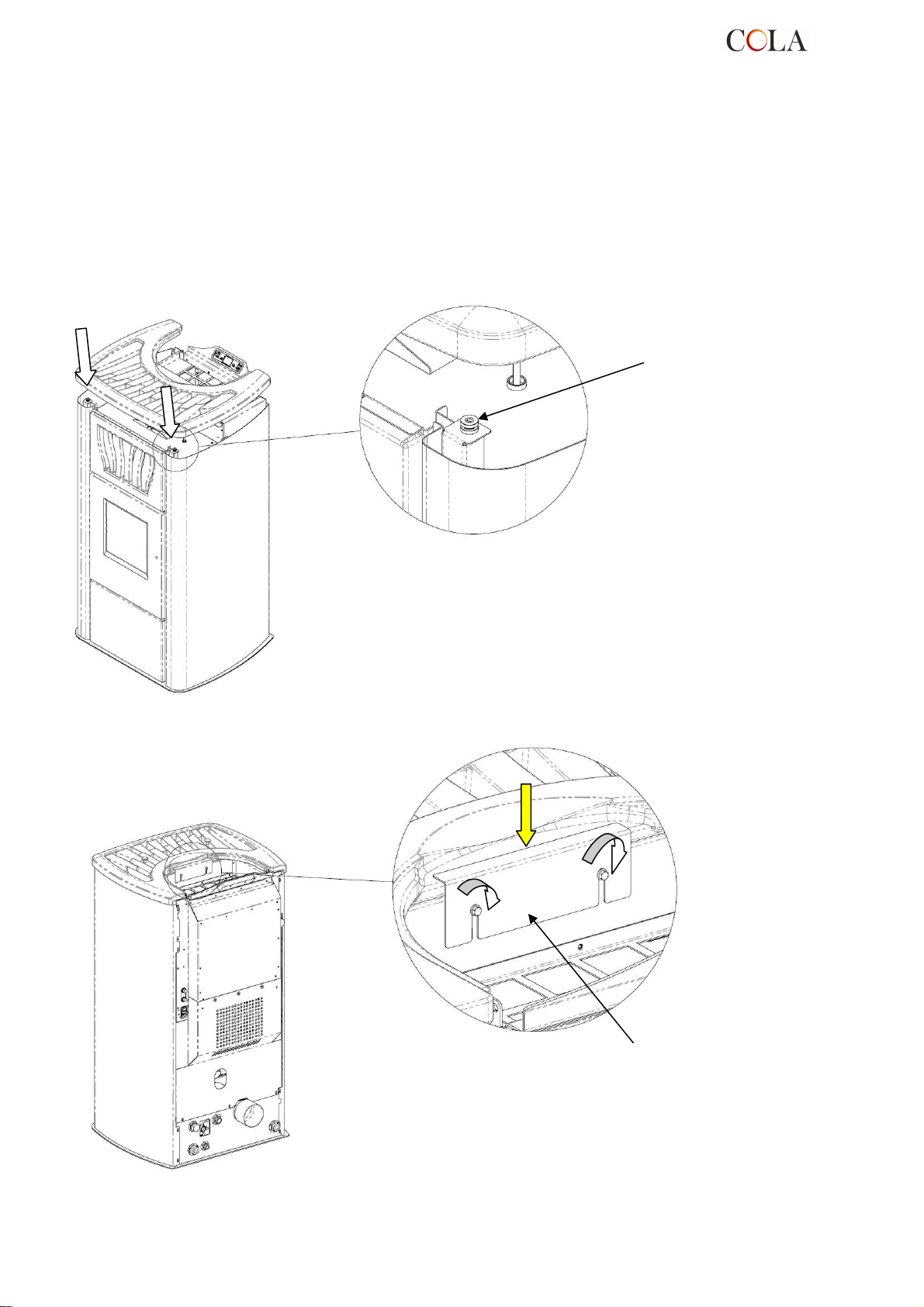
DETAIL
A
DETAIL
B
2.1.1
Fitting the TERMO POWER cover
The appropriately wrapped and protected cover is inside the packing:
- unpack it carefully, check the integrity of the part and install it after placement of the stove, as follows:
X - position the cover, respecting the position of the 2 vibration dampers (detail A) on the stove which allow its
centring.
Y - secure the cover in place, fixing the middle stop without forcing, as shown in the figure.
X
Vibration
damper
Y
SCALE 1:2
Stop
SCALE 1:2
TERMO-POWER
48
Page 49
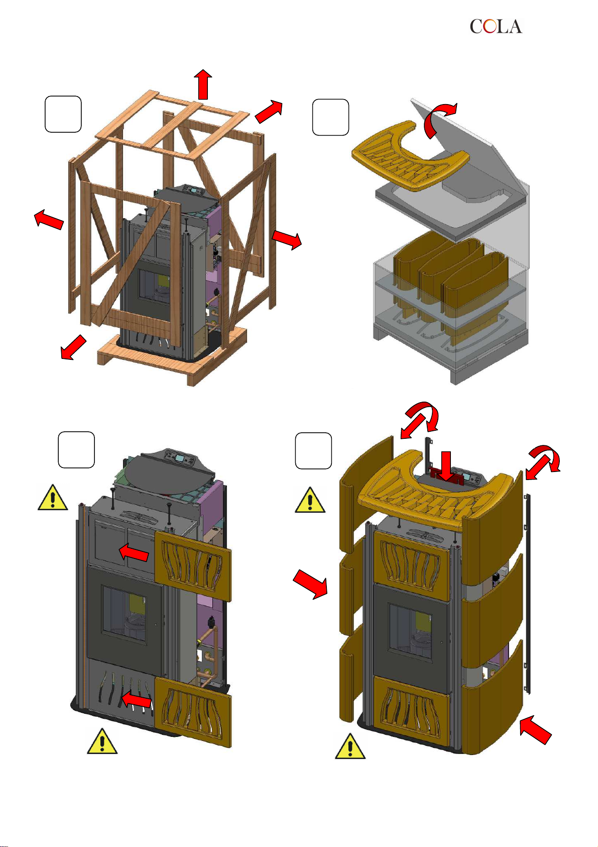
X
4
4
2.1.2
Fitting the TERMO POWER LUX majolica
A
C
B
X
D
TERMO-POWER
49
Page 50
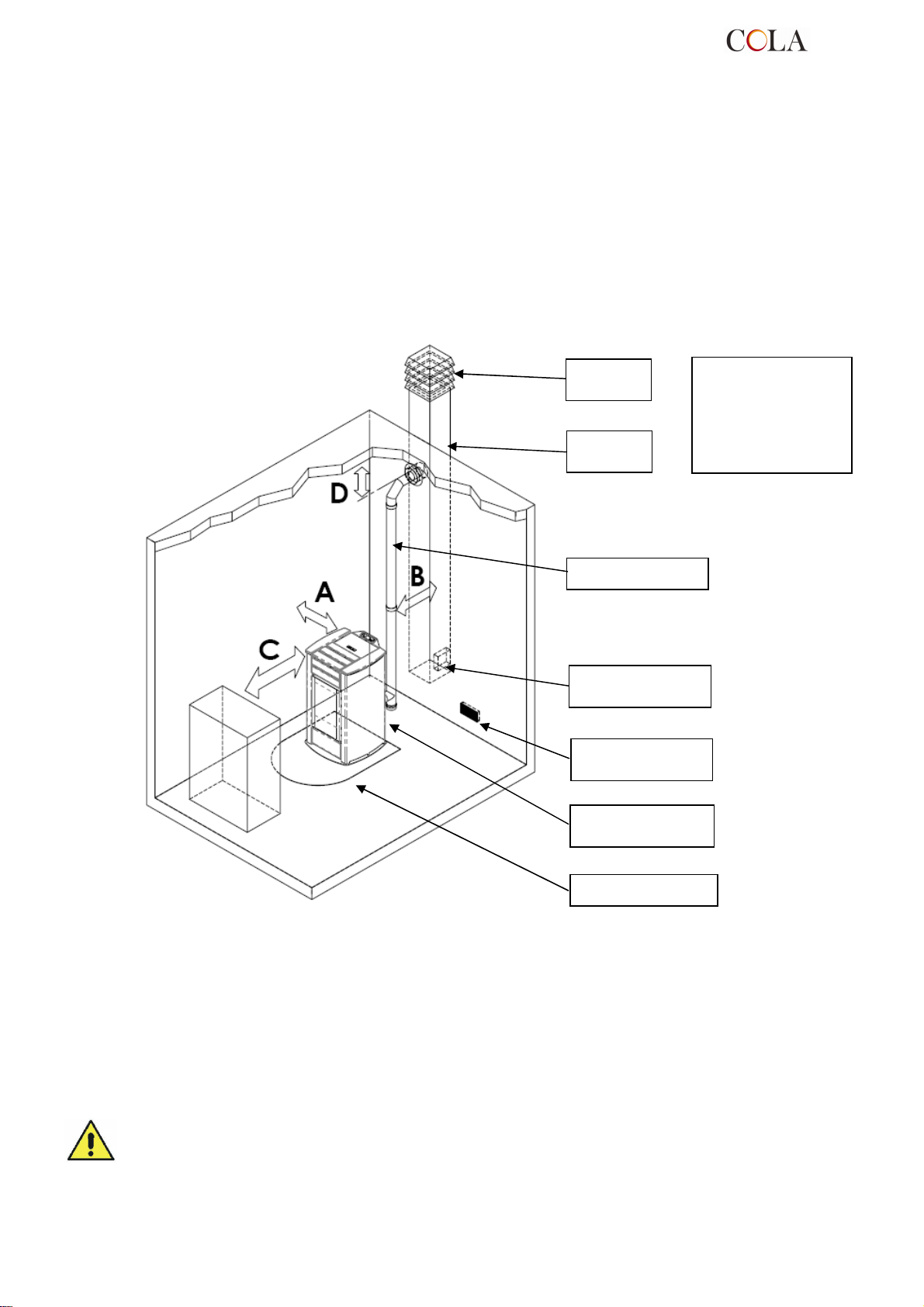
2.2 Place of installation, positioning and fire-prevention safety
The place of installation must be sufficiently ventilated to allow the removal of any combustion smoke leaks.
The unit is suitable for operation in domestic environments with min. temperature of 0°C; it comes com plete with an
antifreeze function that activates the heating pump for system water temperatures below 6°C, safeguarding: the
heating chamber, heating/DHW circuit. The antifreeze function is active only when the stove is electrically powered.
To prevent the risk of fire, the structures surrounding the stove must be protected from the heat. For example, floors
in wood or flammable material must be suitably protected with steel panels or toughened glass. Any wooden boards
or beams above or crossed by the flue must be suitably protected in conformity with the requirements of the specific
current installation standards. Suitable fire-prevention devices should be arranged for any eventuality.
The minimum front distance for the protection of flammable objects is 1.5 m. The minimum safety distances from
flammable materials must be at least 0.2 m and in any case comply with the following table:
Antiwind
grille
Flue
Flue connection
Inspection door on
flue
Wall air inlet
min. 100 cm²
T union with
inspection cap
A = 200 mm
B = 200 mm
C = 1500 mm
D = 200 mm
Floor protection base
Every installation must provide for an easily accessible technical space for periodical maintenance.
The stove is provided with 4 adjustable feet to facilitate positioning on not perfectly flat floors. To adjust the height, tilt
the stove slightly and turn the feet as required.
The stove is supplied with the ambient sensor fixed through a wrapper on the back of the stove; we recommend to
remove the wrapper and to locate the sensor in the best position possible as to improve the temperature registration
in accordance with the ambient context and the length of the cable.
As for temperature registration done at a certain distance we reccomend to install the ambient thermostat/ambient
programming clock-thermostat – see. par.4.8.
The stove cannot be installed in bedrooms, bathrooms and in general in rooms where another heating
unit is already installed without an independent air inflow.
With wooden floors, install a floor protection base in conformity with the current regulations.
Suitable fire-prevention devices should be arranged for any eventuality.
Do not install the stove in places with an explosive atmosphere.
TERMO-POWER
50
Page 51
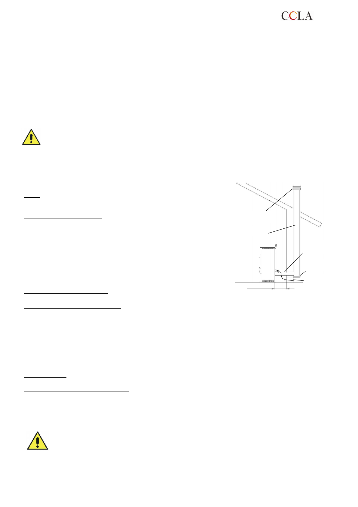
Canna
Comignolo
Presa d’aria
Camera
Distanza min 0.2m
Raccordo
chamber
2.3 Air inlet
The stove air inlet pipe or intake is located at the back and is round and 50 mm in diameter.
The combustion air can be sucked:
from the room, provided there is a wall air inlet near the stove, communicating with the outside and of minimum
►
area 100 cm² suitably protected externally by a grille;
or with connection directly to the outside with a suitable pipe of inside diameter 50 mm and max. length 1.5 m.
►
2.4 Fume exhaust
Fumes can be exhausted through a connection to a conventional flue.
The installer must check the efficiency and state of the flue and its conformity with the
local, national and European regulations.
Certified pipes and connections with adequate seals guaranteeing their tightness must be used.
In case of fire, shut down the stove, promptly call the fire department, and avoid continual attempts to
extinguish it.
Types of installation
Listed below are definitions and requirements for correct installation of an
exhaust flue in accordance with Italian Standard UNI10683:
FLUE : a vertical duct for collecting and expelling, at an appropriate height
from ground, the fumes coming from a single unit and, where permitted,
more than than one.
FLUE technical requirements :- it must be fumetight, isolated and insulated
depending on its use;
- it must have a mainly vertical path with axis deviation < 45°;
- it must be at a suitable distance from flammable materials with insulation
or air gap;
- it must preferably have a constant, free and independent round internal
section;
- it is advisable for the flue to have an inspectionable chamber for the
collection of solid materials
- and any condensate, placed under the beginning of the fume duct.
FLUE CONNECTION or DUCT: duct or connection element between the
unit and flue for evacuation of fumes.
DUCT technical requirements:
- it must not cross rooms in which the installation of combustion units is not
allowed;
- flexible metal tubes or fibre cement pipes are prohibited;
- the use of counter-sloping elements is prohibited;
- horizontal sections must have an upward slope of at least 3°;
- the length of the horizontal section must be minimal and not more than 3 m;
- there must not be more than 3 changes of direction, without the T union;
- with change of direction > 90° a max. of 2 bends can be used with length in horizontal projection not exceeding 2 m
- the fume duct must have a constant section and allow the recovery of soot.
CHIMNEY CAP: a device placed on the top of the flue to facilitate the dispersion of fumes into the
atmosphere.
CHIMNEY CAP technical requirements: - it must have a section equivalent to that of the flue;
- it must have a useful section not less than double the internal section of the flue;
- it must prevent the entry of rain and foreign bodies and ensure the discharge of fumes in any
atmospheric condition;
- it must ensure an adequate dilution of fumes and be positioned outside the backflow area;
- it must be without mechanical means of suction.
The direct discharge of fumes must take place on the roof and not towards closed spaces
( even open air ).
Antiwind
antivento
grille
Flue
fumaria
Min. distance 0.2 m
Flue
connection
fumi
Inspectionable
ispezionabile
Ext. air inlet
esterna
min.100 cm 2
min.100 cm
2
TERMO-POWER
51
Page 52
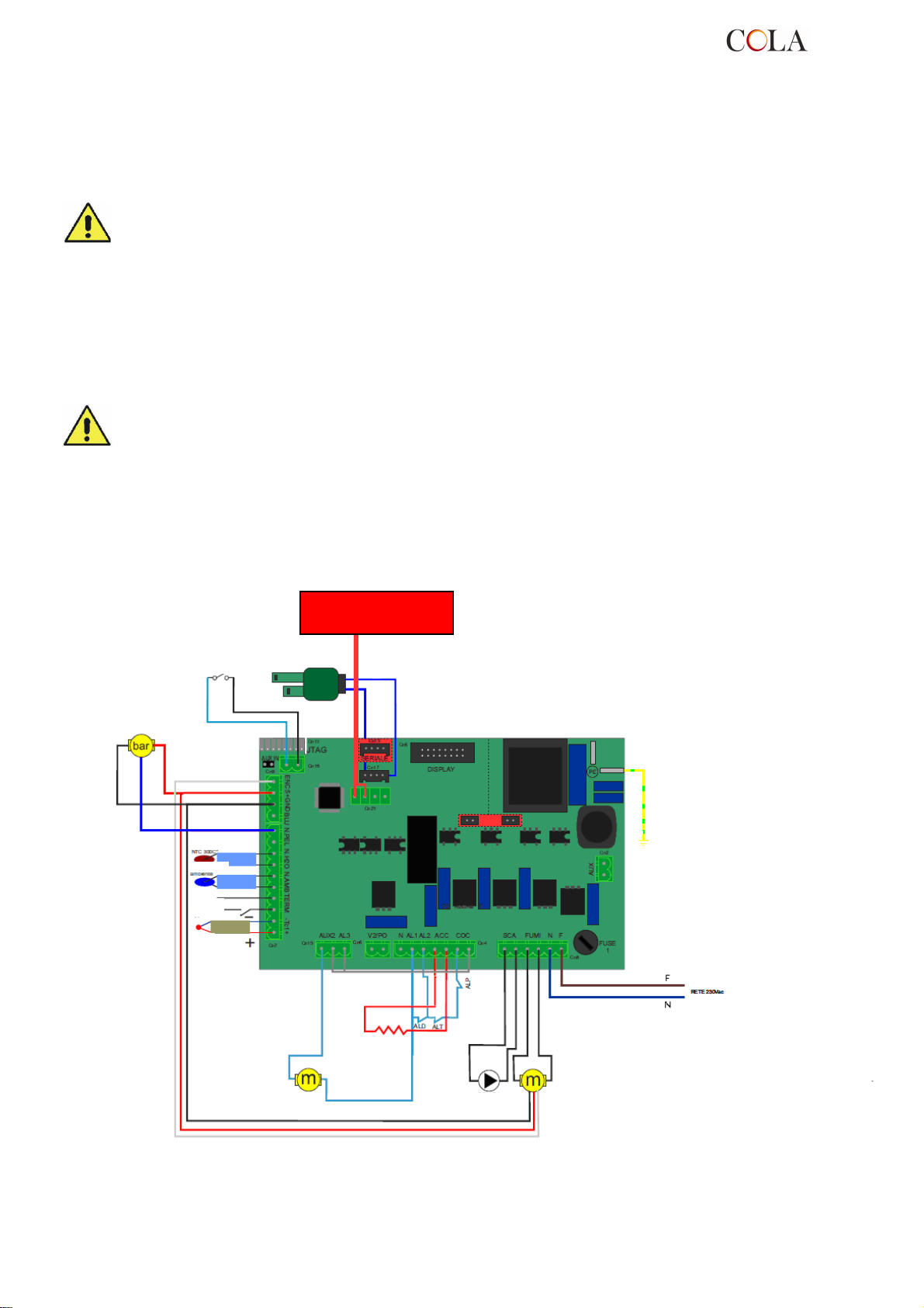
ON
ALT=
ALD=
ALP=
PUMP
room probe
AUGER
2.5 Turbulator and baffle position check
Before lighting the stove make sure the brazier is in the correct position, i.e. fitted in the special slots. Also make
sure the turbulator shaker device is resting in a lower position. An incorrect position of the brazier and/or turbulators
can result in malfunctioning and excessive blackening of the glass.
At every stove lighting check the correct position of the brazier and turbulator shaker device.
2.6 Electrical connection
Connect one end of the power cable to the rear socket of the stove, and the other to the wall socket.
The voltage supplied by the system must match that specified on the stove dataplate and in the technical data
section of this manual.
During stove idle periods it is advisable to remove the power cable.
Make sure the electrical system is equipped with an earth and differential switch
in accordance with the current Regulations.
The power cable must never touch the stove exhaust pipe.
2.7 Wiring diagram
2.7.1 Base wiring diagram
DHW BOILER
THERMOSTAT/FLOWSWITCH
PRESSURE
TRANSDUCER
NTC
Fume verifier encoder
suppl.
thermostat
fume
probe
PLC additional
accessories and consol
AIR FLOW METER
BOARD L023
IGNITER
EARTH
Heating chamber safety thermostat
Low pressure gauge
Pellet compartment safety thermostat
Fume verifier encoder
FUME EXTRACTI
FAN
TERMO-POWER
52
Page 53
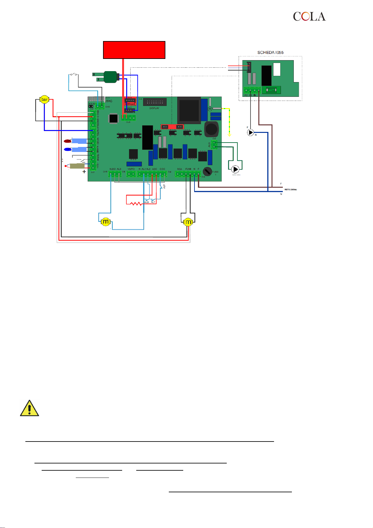
FUME EXTRACTION
ALT=
ALD=
ALP=
room prob
e
AUGER
2.7.2 Wiring diagram with sanitary pump
PLC additional
accessories and consol
DHW BOILER
THERMOSTAT/FLOWSWITCH
PRESSURE
TRANSDUCER
NTC
probe
suppl.
thermostat
Fume verifier encoder
fume
probe
AIR FLOW METER
BOARD L023
EARTH
PUMP
SANITARY
PUMP
IGNITER
Fume verifier encoder
FAN
Heating chamber safety thermostat
Low pressure gauge
Pellet compartment safety thermostat
2.8 Wiring diagram for zone system
Before installing the heating stove in the house, check the type of heating system;
in case of several zones, a special electronic controller for multi-zone circuits, available as an optional, must be
installed. This is to prevent overheating of the heating chamber due to possible simultaneous closing of the zone
valves and consequent stopping of hot water flow.
2.9 Plumbing connections
The heating capacity of the unit must be previously established by calculating the building's heat requirement
according to current regulations. The system must be provided with all the components for correct and regular
operation; in fact according to the rules of proper workmanship in installation, shutoff valves and non-return valves
allowing the stove to be isolated in case of maintenance and/or checks, must be interposed between the stove and
the heating system.
Proceed slowly during heating chamber water filling, to allow correct and complete evacuation of the air from the
vent.
The pellet stove has an internal heating circuit complete with circulating pump, safety valves, air vent, temperature
probes and pressure transducer.
If the heating system is managed in zones a multi-zone controller, available on request, must be installed.
During stove transport the gaskets in the plumbing system may come loose and/or break, causing water
leaks during normal operation; therefore make sure to check the tightness of the circulating pump and
heating chamber connection rings and vent the residual air during water filling and after the first hours of
operation.
To connect the stove to a heating system it is advisable to contact a competent technician in order to best optimise
the plumbing connections and the performance of the entire system without compromising stove operation.
One of the following optionals must be requested for the connection to the DHW circuit:
- a DHW pump on the delivery manifold with respective connection pipes for placing inside the stove
- or a DHW pump, plate exchanger
- or a monostable 3-way valve for installing outside the stove.
The request for these accessories must go with the supplementary electronic board model ‘I055’ for management of
commands with possible upgrading of software to be placed on the control main board.
and connection pipes for placing inside the stove
TERMO-POWER
53
Page 54
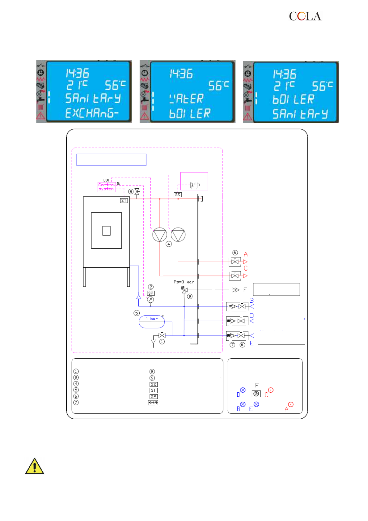
Pellet heating
KEY
Int. volume 23.5 l
t
.
with the unit
After completing the DHW connection it is necessary to access the technical menu of the control and select the type
of circuit; every specific DHW function set: DHW EXCHANGER, BOILER or DHW BOILER appears on the display at
the moment of heating-DHW switchover with one of the messages given below and remains until the end of the
DHW request by the thermostat or flow switch :
Hydraulic diagram - heating pellet stove ref. COLA 20-25kW-07-2011
Heating pellet stove
Thermostat
chamber - 2011
Pt=20-25 kW
Heating DELIVERY
male 1“
Heating DELIVERY
male 3/4“
OVERPRESSURE WATER
DISCHARGE F1/2”
Drain cock
Pressure sensor / Pressure gauge
Circulating pump
Membrane pressure vessel
Shutoff valve / Cock
Non-return valve
Circuit / heating chamber air ven
Safety valve P max 3 bar
Safety sensor T > 85°C
Water temperature sensor
Circuit pressure sensor
Valves to be included in system
during installation – not supplied
2.10 Emergency
Suitable fire-prevention devices should be arranged for any eventuality.
In case of a fire, proceed as follows:
- Immediately disconnect the plug;
- Extinguish the fire using suitable fire-extinguishers;
- Call the fire department immediately;
- Do not use jets of waters to extinguish the fire.
Heating RETURN
male 1“
Heating RETURN
male 3/4“
Water supply F1/2”
Pmax 2 bar
Arrangement
PLUMBING CONNECTIONS on back of
stove
TERMO-POWER
54
Page 55
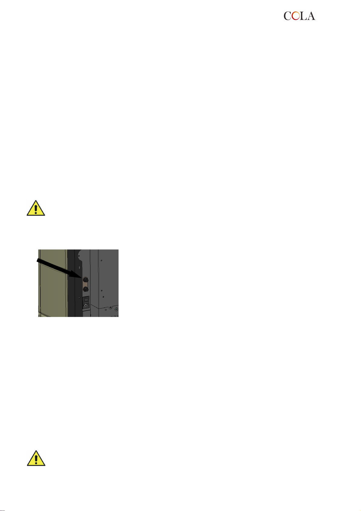
3 STOVE SAFETY
3.1 Safety distance from flammable materials
To prevent the risk of fire, stove positioning must respect a minimum distance from flammable materials, according
to that given in the technical table of the manual and on the dataplate.
Pay attention to the type of floor: for delicate and flammable materials it is advisable to use plates in steel or
toughened glass as a support base (see section 2 - Transport and Installation). In case of particularly fragile objects
such as furniture, curtains or sofas, increase the stove distance considerably.
3.2 Fume exhaust safety
In normal operation the combustion chamber is in a negative pressure, guaranteeing seal against possible smoke
leaks in the room. If a certain vacuum level is not reached or the fume exhaust outlet is blocked, the vacuum switch
detects the lack of a negative pressure inside the combustion chamber or the air flow meter detects a lack of air flow
and, through the electronic controller, switches off the auger rotation motor, signalling the anomaly with a message
on the control panel 'AL8 NO NEG PRESS' or 'AL9 INSUF DRAUGHT'.
3.3 Combustion chamber overpressure safety
Any and/or sudden overpressures in the combustion fumes inside the chamber and fume exhaust ducts are
discharged by opening of the safety valves located on the heat exchanger. During normal operation these valves are
kept closed by their weight and the negative pressure in the combustion chamber, guaranteeing a seal against any
smoke escaping.
Periodically check closing, the integrity of the device and its operation.
3.4 Overheating - safety thermostats
On the front and bottom of the hopper, and precisely on the pellet
chute and on the top part of the heating chamber, there are two
temperature probes connected to the respective safety thermostats
that automatically shut off the pellet supply in case of excessive
heating. In this case the extractor and/or fans continue working,
allowing the stove to cool down rapidly. The fault is displayed on the
control panel with a message 'AL 7 THERMAL SAF'. In case of
activation, proceed as follows:
Allow the stove to cool down for at least 45 minutes.
►
Reset the thermostat by pressing the button near the switch on
►
the back of the stove (figure opposite).
Restart the stove normally.
►
Pellet hopper thermostat activation temperature: > 85°C
Heating chamber thermostat activation temperature: > 95°C
3.5 Safety against flare-back in the pellet chute
The solutions preventing flare-back are:
negative pressure in the combustion chamber see par. 3.2.
►
the siphon shape of the pellet chute.
►
the hopper temperature safety see par. 3.4.
►
3.6 Overcurrent protection device
The unit is protected against overcurrent by 2A fuses on the power supply of the main stove switch located at the
back.
3.7 Power failure safety
A temporary power failure does not limit stove safety and the hopper temperature does not reach high values
(< 85°C), given the small quantity of pellets burning in the brazier.
This anomaly can result in some smoke briefly escaping into the room, which does not involve any risk.
Do not tamper with the safety devices.
TERMO-POWER
55
Page 56
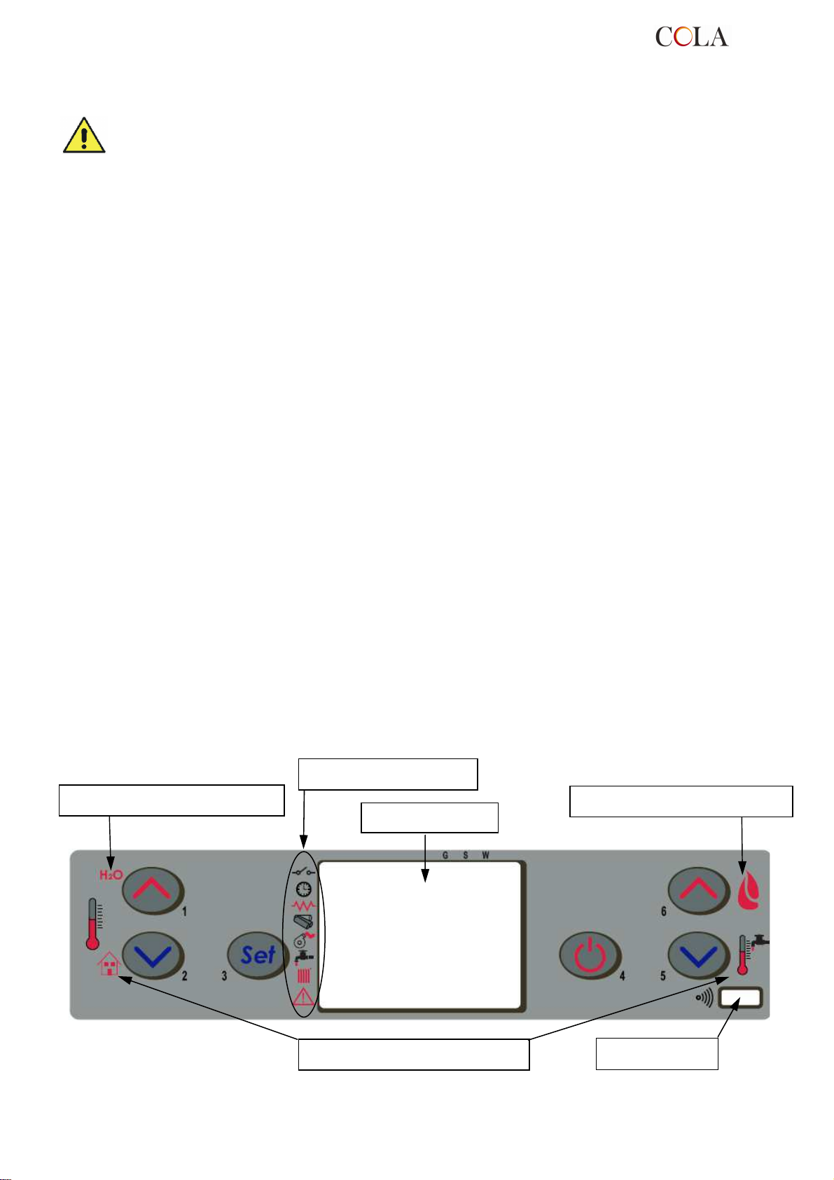
Backlit LCD
3.8 Plumbing circuit overpressure safety
A possible overpressure of the water inside the chamber, by P>3 bar, is discharged through activation of the safety
valve installed in the plumbing system inside the stove.
Do not tamper with the safety devices.
3.9 Fume extractor fan failure
If the fume extractor fan stops for any reason, the electronic controller instantly stops the pellet feed, displaying the
message 'AL4 FAN FAIL'.
4 STOVE USE
4.1 Introduction
The pellet stove has the advantage of combining heat from a wood flame with the convenience of automatic
management of temperature and the possibility of weekly programming of lighting and shutdown.
Connection to an external thermostat and/or chronothermostat is possible for detecting the temperature in a different
place from where the stove is installed.
For safe and reliable use:
- when lighting and using the stove the first time, unpleasant odours may be created, therefore air the room
thoroughly;
- the hopper must only be filled with pellets; make sure the bag does not come into contact with the hot surfaces
of the stove;
- do not put any fuel other than the prescribed pellets in the hopper;
- the stove must not be used as a waste incinerator;
- the stove must only operate with the fire door always closed.
- the fire door seals must be checked periodically to prevent air from entering;
- to guarantee efficient performance and correct operation it is necessary to carry out periodical cleaning of the
brazier every time pellets are loaded;
- when lighting the stove for the first time, allow it to heat up gradually by setting low operating temperatures (see
section on temperature setting);
- during lighting, operation and shutdown, the stove may creak a little due to the heat expansion.
4.2 Description of control panel
The control panel comprises a backlit LCD, on/off button 'P4’, SET/MENU button ‘P3’, four menu buttons 'P1’, ‘P2’,
‘P5’, ‘P6’, and seven stove operation status LEDs.
Top display indications
Status indicators
Top display indications
TERMO-POWER
Bottom display indications
56
IR receiver
Page 57
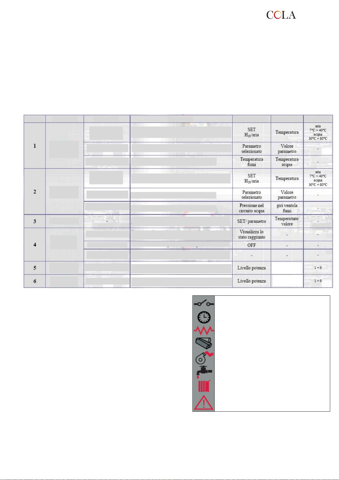
Temperature value (if enabled)
The panel enables stove lighting and shutdown, adjustment during operation and the setting of management and
maintenance programmes.
The display shows all the information on stove operation status.
To access the menus, proceed as follows:
- press the SET button ‘P3’;
- press the buttons ‘P5’,‘P6’ repeatedly to scroll the various menus;
- press one of the increase/decrease buttons ‘P1’, ‘P2’, to set the required parameter;
- press the SET button ‘P3’ to confirm the parameter value.
On accessing the menu it is possible to obtain the various types of displays and carry out the available settings
depending on the access level.
Given below is the table of controls and respective messages displayed during programming or setting operation
parameters:
Button
Description Mode Action Top display Bottom display
Limits
TEMPERATURE
Increases the room and water thermostat temperature value
SETTING
Increase
temperature
Decrease
temperature
Setting/menu
PROGRAMMING
WORK
TEMPERATURE
SETTING
PROGRAMMING
WORK
WORK
Increases the selected parameter
Displays temperatures
Decreases the room and water thermostat temperature value
Decreases the selected parameter
Displays stove operation status
Access the temperature SETTING and user and technician
parameters menu by successive pressing
Press for 2 seconds to switch the stove on or off (if off or on)
ON/OFF
reset
Decrease
power
Increase
power
BLOCK
PROGRAMMING
WORK
WORK
Resets the stove and returns it to off status
Exits the programming menu at any point of modification.
The changes are saved
Decrease output or the DHW boiler water thermostat
Decrease output or the DHW boiler water thermostat
Temperature value (if enabled)
Increase output or the DHW boiler water thermostat
Increase output or the DHW boiler water thermostat
Temperature value (if enabled)
Temperature value (if enabled)
The Figure opposite describes the meaning of the status
indicators in the left part of the display.
Activation of one of the segments on the display signals
activation of the corresponding device according to the list
opposite.
4.3 Lighting
4.3.1 Check before lighting
Before lighting the stove:
- make sure you have read and understood that given in the manual;
- the hopper must be filled with pellets;
Sanitary SET
Temperature
Sanitary SET
Temperature
External contact
Chrono
Electrical element
Auger
Fume extractor
DHW circuit activation
HEATING circuit activation
ALARM
TERMO-POWER
57
Page 58
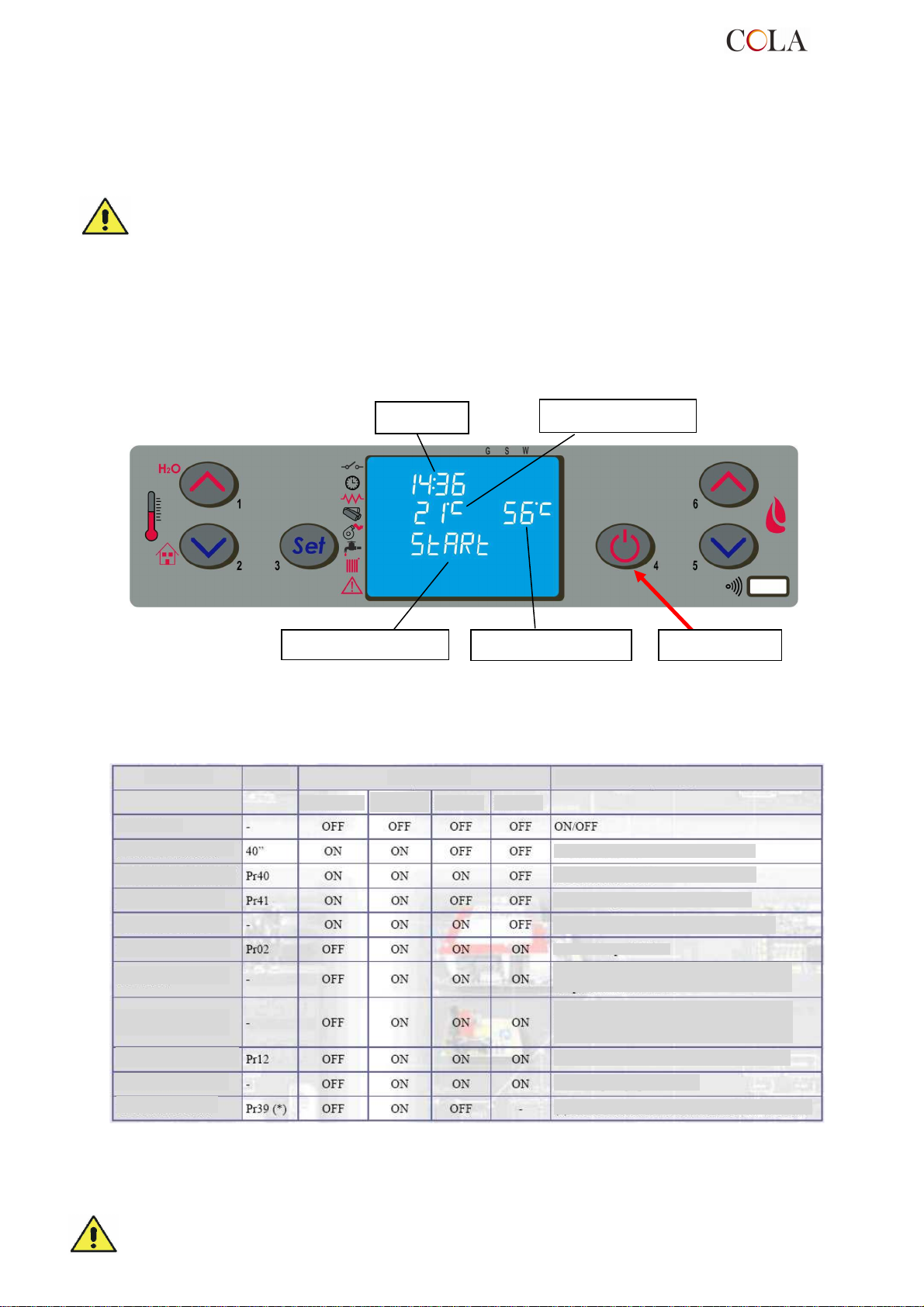
Dialogue box
Button ‘P4’
exhaust
After
after tim
e Pr02
- the combustion chamber must be clean;
- the brazier must be completely free, cleaned of any combustion residuals and correctly fitted in the brazier
holder;
- check hermetic closing of the fire door and ash pan;
- check the connection of the power cable and switching to ON/1 of the switch located on the back of the stove.
- check opening of the delivery and return shutoff valves as well as the water circuit pressure.
- At first startup, remove all the components (instructions/label) that could burn from the stove firebox and
glass.
- Any lightings done after long stove idle periods require the renewal of any pellets that have been inside
the hopper for a long time, in being a damp fuel no longer suitable for combustion, and complete
cleaning of the combustion chamber.
4.3.2 Startup stage
To light the stove, press the button ‘P4’ for 3 seconds: the message ‘START’ will appear on the display.
The stage is automatic and managed entirely by the electronic controller without the possibility of changing the
parameters.
Clock
Room temperature
Water temperature
The stove carries out the startup stages in sequence according to the procedures defined by the parameters that
manage levels and times, reaching the work condition unless anomalies or alarms occur, according to the following
table:
Status
OFF
START – CLEANING
PELLET PREFILL
WAITING FLAME
PELLET LOAD
FIRE PRESENT
WORK
MODULATES WORK
BRAZIER CLEANING
WORK
FINAL CLEANING
Duration
Igniter
Fume
Devices
Auger Exch.
Conditions for going to next status
After time Pr40
After time Pr41
After time Pr41
Fume temperature > Pr13
Room temperature < SET temperature
Fume temperature < Pr14
Room temperature < SET temperature
Water temperature < water SETTING
Fume temperature < Pr14
Every Pr03
ON/OFF to switch off
(*) Pr39 Starts from when fume T.< Pr13
After a certain time has elapsed, if the fume temperature has not reached the minimum permissible value the stove
goes in alarm status.
- Do not use flammable liquids to light the stove.
TERMO-POWER
58
Page 59
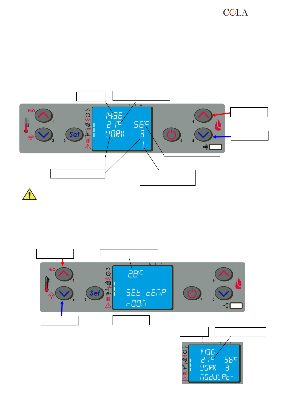
Dialogue box
Button ‘P6’
Dialogue box
Butto
n ‘P1’
Button ‘P2’
Clock
Room temperature
- In case of persistent failed lighting, contact the Service Centre.
As an alternative it is possible to switch-on the stove if you press the buttons P4 and P5 at the same time for 3
seconds. è possibile accendere la stufa premendo contemporaneamente il pulsante P4 e P5 per 3 secondi. On the
display it will appear “Waiting for request”. In this way the stove is in stand-by and it starts again only when it
recognises a demand for warming the ambient or the sanitary water (if available).
4.4 Work stage
After the 'STARTUP' stage, the stove goes to the 'WORK' mode which represents the normal operation mode.
The user can adjust the heat output from the max. value of 5 to a min. of 1 with the buttons ‘P5’ and ‘P6’.
Clock
Room temperature
Button ‘P5’
Water temperature
Output set to 3
- Make sure to check the pellet level in the hopper so that the flame does not go out due to lack of
pellets.
- Make sure the stove is off when loading pellets.
- The pellet hopper lid must always remain closed; it must only be opened when loading fuel.
- The bags of pellets must be kept at least 1.5 m from the stove.
Real output in work
equal to 1 - flashing
4.4.1 Modifying the room temperature setting
To modify the room temperature just select the MODIFY ROOM SET mode by pressing the button P2.
Then use the buttons ‘P1’ and ‘P2’ : the display shows the current SET temperature status.
Room temperature set
When the fume temperature rises the maximum value set, the
display will show the message ‘MODULA F’ (‘MODULATION F’)
and the stove starts the modulation of the flame authomatically. On
the contrary when the temperature goes over 280°C the display
will show the alarm ‘ALARM HOT FUMI’ (‘ALARM HOT FUMES’)
and the stove will start the switch-off procedure.
TERMO-POWER
59
Page 60
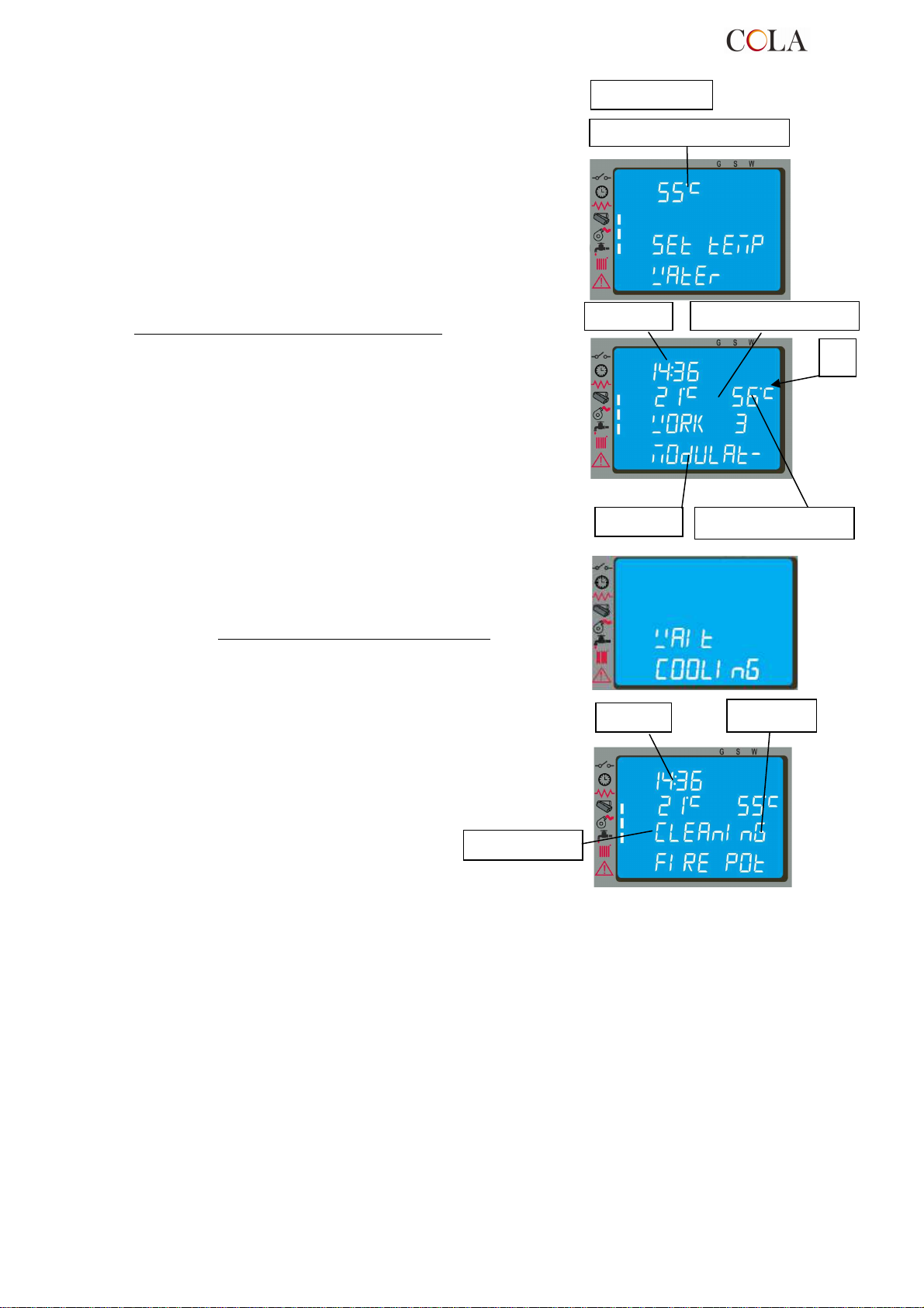
Dialogue box
Dialogue box
Water temperature set
Clock
Room temperature
Dialogue
Clock
4.4.2 Modifying the water temperature setting
To modify the water temperature just select the MODIFY WATER
SET mode by pressing the button P1.
Then use the buttons ‘P1’ and ‘P2’ : the display shows the current
SET temperature status.
When the water temperature has reached the set value,
as a condition also at the same time as that described in par.4.4.1,
the output is automatically brought to the min. value,
MODULATION status.
As for idro model stove, when the water temperature parameter
can’t be reached, the activation of led [ A ] starts.
Water temperature
A
4.4.3 Restart from STANDBY
After shutdown, the stove goes to cooling status, bringing the fume
extractor speed to the set value for brazier cleaning. Relighting
occurs as soon as the room temperature reach the SET value.
4.4.4 Cleaning the brazier
During normal operation in work mode, the 'BRAZIER CLEANING'
mode is activated at fixed intervals for a set duration.
Set output
4.4.5 Water heater with heat exchanger quickly
When hot water is required, the display shows the word SCAM HEALTH and LED lights shown from the tap. The
function, however, is only executed if the stove is lit, and has reached a sufficient temperature inside the camera.
In the remaining cases the service is not provided.
4.4.6 Water heater with storage tank
This type of installation requires the use of an external thermostat, which measures the temperature of the water of
the kettle. When the temperature drops below the set temperature of SET in the external thermostat activates the
function of health, the display shows the message of the stove and boiler HEALTH LED lights shown from the tap
until the request is satisfied.
If the stove is in the HOLD step REQUEST automatically turns on and you put in WORK. Once the temperature of
water in the camera work, you turn the water supply to the boiler.
SET When the temperature of the tank is met, the oven converts waste heat to the heating for about 2 minutes and
then, if there is another request, it waits or REQUEST MODULATION, according to the settings ( see prg. 4.6.5).
If the stove is in the OFF state, no lights and does not provide the service.
TERMO-POWER
60
Page 61
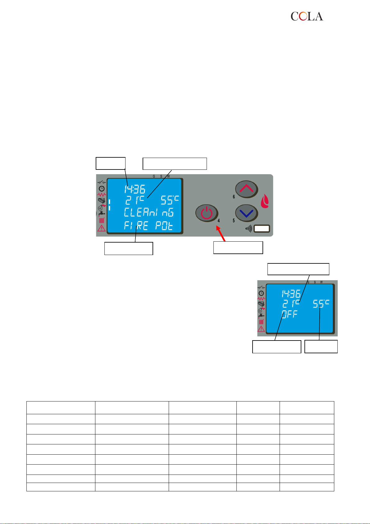
Clock
Room temperature
Room temperature
4.4.7 System with puffer / heat storage
This type of installation requires the use of an external thermostat, which measures the temperature of the puffer.
When the temperature is lowered below the temperature of SET set in the external thermostat, in the stove display
shows the message WATER PUFFER or BOILER WATER and light up the 2 LEDs respectively indicated by the tap
and from the radiator as it can meet the plant heating system.
If the stove is in the HOLD step REQUEST automatically turns on and goes into WORK and reached the working
temperature of the water in the camera, you turn the water supply to the puffer.
SET When the temperature of the puffer is satisfied, the stove is placed in a HOLD REQUEST (it is recommended to
set the function ON STAND-BY, see prg. 4.6.5).
If the stove is in the OFF state, no lights and does not provide the service.
4.5 Shutting down
To shut down the stove, just press the button 'P4' for about 2 seconds.
The auger is immediately stopped and the fume extractor is brought to high speed, making the message
'CLEANING' appear on the display.
Dialogue box
Button ‘P4’
At the end of the operation the message 'OFF' appears in the
dialogue box.
During the shutdown stage the stove cannot be restarted until the
fume temperature has fallen below a set value for a fixed time, with
the message 'WAITING COOL' appearing in the dialogue box.
Dialogue box
Water T
4.6 Menu
Press the button ‘P3’ (SET) to access the menu; this is divided into various items and levels for accessing the
settings of the electronic controller.
The following table summarises the menu structure with the selections available to the user.
Level 1 Level 2
Level 3
Level 4
Value
02 – set clock
02 - hours Hours
03 - minutes Minutes
04 - day Day
05 - month Month
06 - year Year
03 – set chrono
TERMO-POWER
01 - day Day
01 – enable chrono
61
Page 62

04 – week
-
end
01 – enable chrono on / off
01 – day chrono on / off
02 – start 1 day time
03 – stop 1 day time
04 – start 2 day time
05 – stop 2 day time
01 – week chrono on / off
02 – start 1 day time
03 – stop 1 day time
04 – Monday prog 1 on / off
05 – Tuesday prog 1 on / off
07 – Thursday prog 1 on / off
08 – Friday prog 1 on / off
09 – Saturday prog 1 on / off
10 – Sunday prog 1 on / off
11 – start prog 2 time
12 – stop prog 2 time
13 – Monday prog 2 on / off
14 – Tuesday prog 2 on / off
16 – Thursday prog 2 on / off
17 – Friday prog 2 on / off
18 – Saturday prog 2 on / off
19 – Sunday prog 2 on / off
20 – start prog 3 time
21 – stop prog 3 time
22 – Monday prog 3 on / off
23 – Tuesday prog 3 on / off
25 – Thursday prog 3 on / off
26 – Friday prog 3 on / off
27 – Saturday prog 3 on / off
28 – Sunday prog 3 on / off
29 – start prog 4 time
30 – stop prog 4 time
31 – Monday prog 4 on / off
32 – Tuesday prog 4 on / off
34 – Thursday prog 4 on / off
35 – Friday prog 4 on / off
36 – Saturday prog 4 on / off
37 – Sunday prog 4 on / off
02 – start 1
04 – select language
01 - Italian set
02 - French set
03 - English set
04 - German set
02 – day program
03 – week program
06 – Wednesday prog
15 – Wednesday prog
24 – Wednesday prog
33 – Wednesday prog
01 – week-end
03 – stop 1
04 – start 2
05 – stop 2
on / off
on / off
on / off
on / off
on / off
TERMO-POWER
62
Page 63
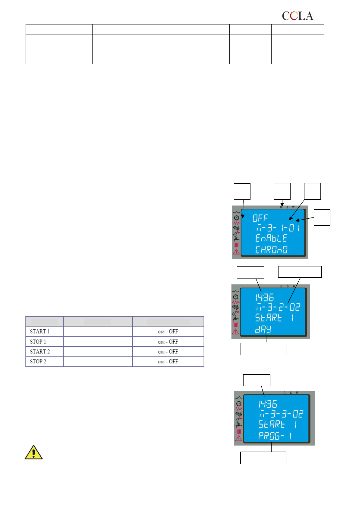
Input
Menu level
Input
Se
Activation time
Activation time
Deactivation time
Deactivation time
05 – standby mode
06 – buzzer
07 – initial loading
08 – stove status
on / off
on / off
set
-
4.6.1 Menu 01 – adjust fans
The item of menu 01, if enabled, adjusts the speed of the supplementary fans (not available).
4.6.2 Menu 02 – set clock
Before operating with the stove it is necessary to set the current time and date so that there is a reference for
possible chrono programming.
The electronic control device has a lithium battery mod. CR2032 of 3 Volt inside. It allows the internal clock to last
over 4-5 years; if the clock signal does not appear when the stove is off or when switching the stove again a series of
“0000” appears, it means it has to be substituted and you need to call one of our service point authorised for its
substitution.
4.6.3 Menu 03 – enable chrono
Allows all chronothermostat functions to be enabled/disabled.
Regarding the selection and entering of times, use the six buttons,
following the table in par. 4.2.
It allows to enable and disable all the thermostat functions programmed;
with the set ON you activate this function and it appears the led
[ D ] related to it.
When the daily, weekly, or week-end program is set you can see
on the upper right side of the display it appears the led [C].
By accessing the submenu: DAY PROGRAM, the daily
chronothermostat functions can be enabled/disabled and set.
It is possible to set two operation phases delimited by the times
set according to the following table where the OFF setting tells
the clock to ignore the command.
lection
Meaning
Possible values
D
C B
A
By accessing the submenu: WEEK PROGRAM it is possible to
enable/disable and set the weekly chronothermostat functions.
The weekly programmer has 4 independent programmes whose
final effect consists of a combination of the 4 programmings.
The weekly programmer can be activated/deactivated; also, by
setting OFF in the times field, the clock ignores the corresponding
command.
TERMO-POWER
Carry out programming making sure not to overlap the
hours of activation and/or deactivation on the same day
in different programmes.
63
Dialogue box
Dialogue box
Page 64
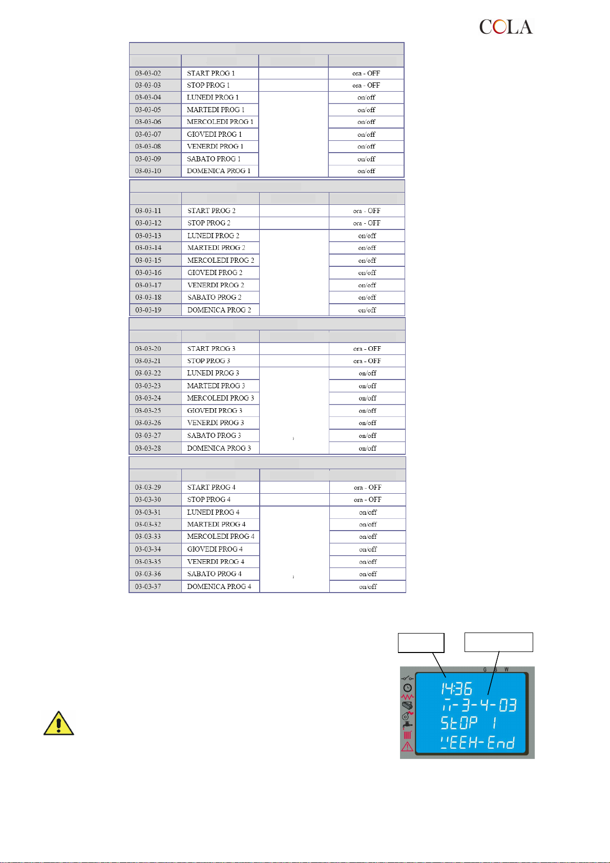
Input
Menu level
PROGRAMME 1
Selection
PROGRAMME 2
Selection
Reference day
PROGRAMME 3
Selection
M
eaning
PROGRAMME 4
Selection
M
eaning
Menu level
Meaning
Activation time
Deactivation time
erence day
Possible values
Menu level
Menu level
Meaning
Activation time
Deactivation time
Activation time
Deactivation time
Possible values
Possible values
Menu level
Activation time
Deactivation time
Possible values
By accessing the submenu: WEEK-END PROGRAM it is
possible to enable/disable and set the week-end (Saturday Sunday) chronothermostat functions.
TERMO-POWER
Activate WEEK-END programming only after
deactivating the weekly programming.
In order to avoid unwanted start and shutdown
operations, activate only one programme at a time.
Deactivate the daily programme if the weekly
programme is required; with this setting it is advisable to
deactivate the week-end programme.
64
Page 65
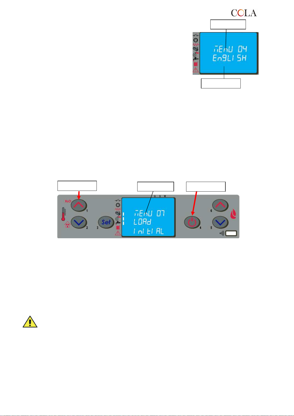
Button ‘P4’
Button ‘P1’
Menu level
Menu level
Dialogue box
4.6.4 Menu 04 – select language
With this selection it is possible to select the dialogue language
from those available entered in the menu, and namely:
- ITALIAN
- FRENCH
- ENGLISH
- GERMAN
4.6.5 Menu 05 – standby mode
With the selection of STANDBY mode ( ON selection ) the stove shuts down automatically after the room
temperature or the water temperature has remained above the SET value for a fixed time.
The next automatic relighting will be possible only when the room temperature or the water temperature falls below
the set value entered in the parameters table (default 2°C).
The manual commands from the control panel or remote control have priority over programming.
With the selection off the stove does not activate the sleep-mode and functions normally activating the
MODULATION when the temperature exceeds the value of SET.
4.6.6 Menu 06 – buzzer
With this selection it is possible to activate/deactivate stove acoustic signalling.
4.6.7 Menu 07 – initial loading
The setting of LOAD INITIAL allows pellet preloading for a time equal to 90 sec. with the stove off or cold. It is
started with the button P1 and stopped with the button P4.
4.6.8 Menu 08 – stove status
With this selection it is possible to display the instantaneous stove status giving the operating status of the various
devices connected to it; various pages placed in succession are available for monitoring.
4.6.9 Menu 09 – settings by technician
This selection is reserved for the authorised technician of the COLA service centre.
Modification of the technical parameters of menu 09 must be done by authorised and competent
personnel; any changes made at random can cause serious damage for which COLA declines any
liability.
4.7 Remote control
The remote control works with the settings made in the control panel and allows stove lighting-shutdown, and
adjustment of the required output and temperature.
Since this device transmits through an infrared diode, it must be pointed at the receiver unit in the control panel.
TERMO-POWER
65
Page 66
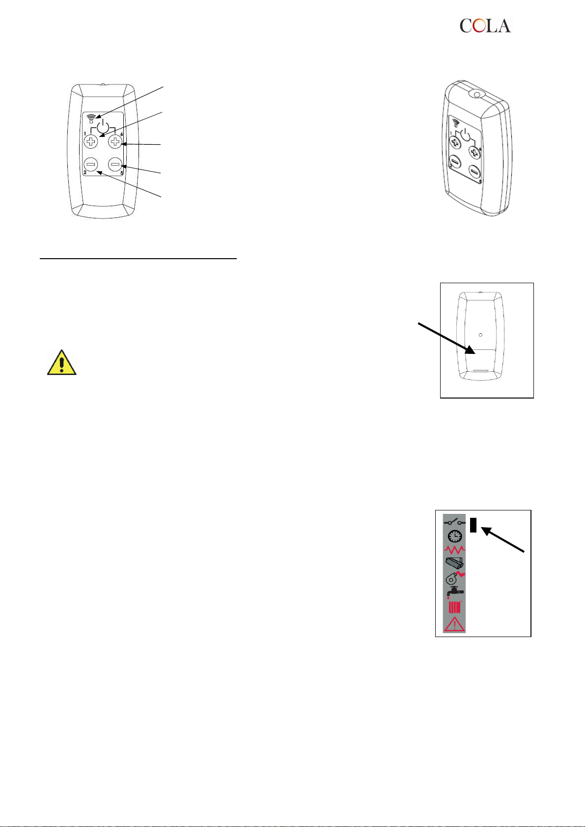
L
The remote control allows the following operations :
: LED lit up by pressing any button
Button P1+P6 : Stove lighting-shutdown
Button P1: Increase room temperature
Button P6: Increase output level
Button P5: Decrease output level
Button P2: Decrease room temperature
4.7.1 Replacing the battery
The remote control comes without the battery; it works
with a battery placed in the lower part of the device.
To fit or replace the battery, proceed as follows:
- Open the cover on the back of the remote control;
- Replace the 12V battery model p23ga, respecting the polarity;
- Close the remote control;
- Check that it works properly;
Keep the remote control away from heat sources and water.
The battery of the remote control must be replaced and disposed of in a safe
way, respecting the local regulations.
4.8 Thermostat - external chronothermostat
The unit controls the room temperature by means of its own digital thermostat whose
function is to detect the temperature through a probe and lower the heat output when
the set temperature is reached.
To use an external thermostat, contact an authorised technician and proceed as
follows:
- turn off the power by means of the main switch on the back and detach the power
cable;
- remove the side panel to access the electronic controller;
- referring to the wiring diagram, connect the two wires of thermostat to the
respective board TERM terminals;
- refit everything and check correct operation.
The setting procedure is as follows:
- external thermostat: SET the temperature to 7°C;
- external chronothermostat: SET the temperature to 7°C and disable the chrono
functions from the menu 03-01.
All the menu functions do not change for each of the settings and signalling of the
connection occurs with lighting up of the segment LED on the status bar of the display.
4.9 Idle period (end of season)
If the stove is not used for long periods, or at the end of each season, it is advisable to proceed as follows:
- remove all the pellets from the hopper;
- disconnect the power supply;
- clean thoroughly and, if necessary, have any damaged parts replaced by qualified personnel;
- protect the stove from dust with suitable covering;
- store in a dry and safe place protected from atmospheric agents.
TERMO-POWER
66
Page 67
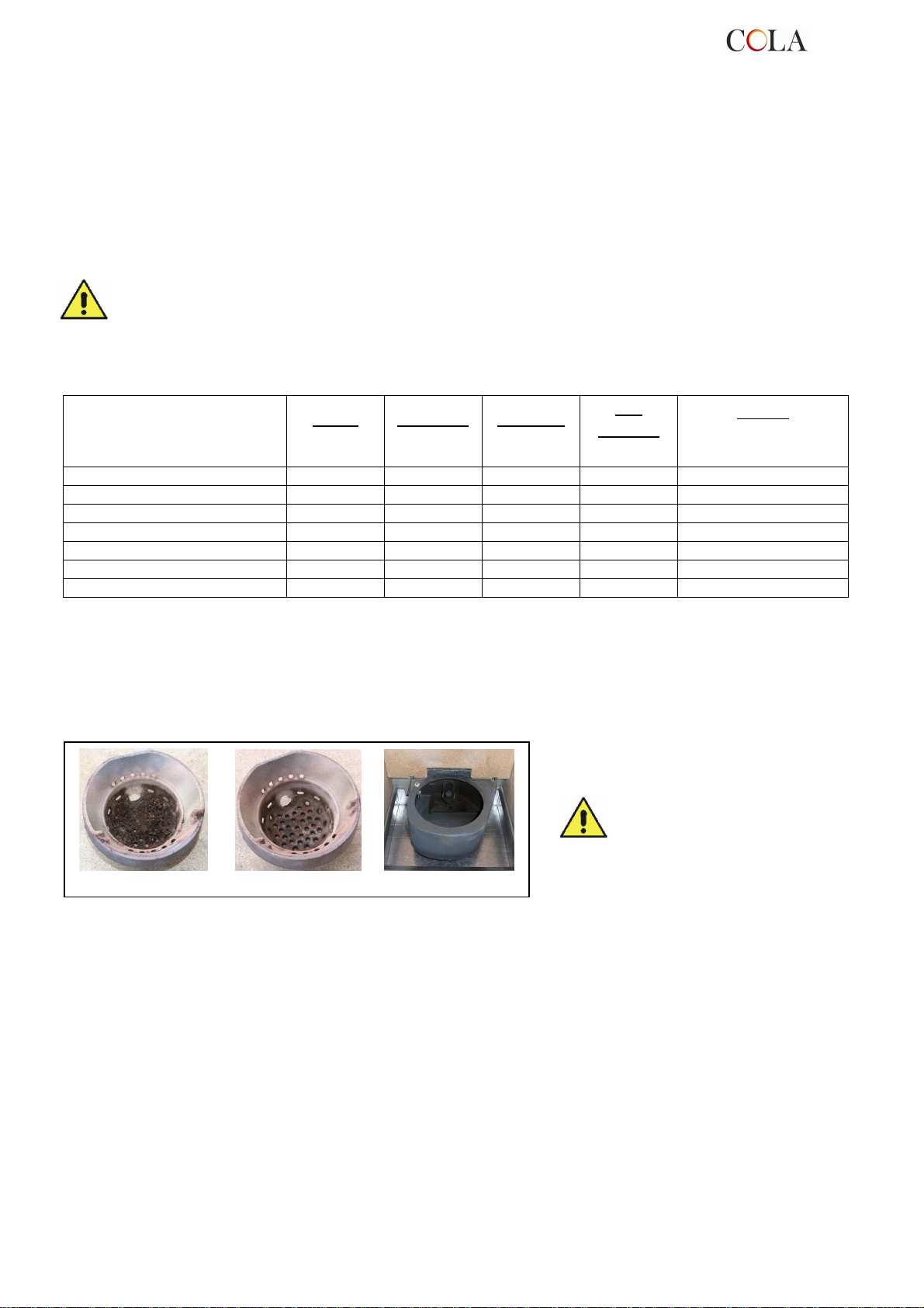
The brazier must rest on the
brazier holder and precisely on
the entire ring band without air
5 STOVE CLEANING
Stove cleaning is very important to prevent: blackening of the glass, poor combustion, deposits of ash and unburnt
products in the brazier, reduced thermal efficiency.
The stove must only operate with the fire door closed.
The fire door seals must be checked periodically to prevent any air from entering; the combustion chamber and
pellet duct work in a negative pressure and the fume exhaust in a positive pressure.
Routine cleaning is normally carried out by the customer following the instructions in the manual, whereas
extraordinary maintenance, at least once a year, must be performed by the authorised Service Centre.
Cleaning operations for all parts must be carried out with the stove unplugged and cold;
Dispose of cleaning waste in accordance with the current local regulations;
The stove must not be operated without its cladding;
Given below are the control and/or maintenance operations for correct stove use and operation.
Brazier
Ash compartment-pan
Door glass
Heating chamber tube bundle
Manifold – fume extractor
Glass - door seal
Pipe - flue connection
5.1 Cleaning the brazier
Remove the brazier and the ash deposited in the combustion chamber and brazier holder. A suitable vacuum
cleaner may be used for this purpose. This operation must be carried out daily, especially in case of accumulated
unburnt matter, to ensure perfect combustion conditions, since the brazier holes allow the flow of combustion air.
Avoid the creation of smoke and unburnt products during lighting and/or normal operation.
2-3
months
routine
cleaning
extraordinary cleaning:
carried out by the Service
Parts / Period
Type of cleaning
1 day
2-3 days
routine
cleaning
■
■
■
■ ■
■ ■
■
■
routine
cleaning
1 month
routine
cleaning
1 year
Centre
gaps.
Brazier dirty Brazier clean Brazier Holder clean
5.2 Cleaning the ash container
The ash container is located directly under the brazier - brazier holder. To clean it, open the fire door and remove the
ash and any combustion residuals using a suitable vacuum cleaner.
Close the door after cleaning. The ash container can be cleaned every 2-3 days depending on stove use.
5.3 Cleaning the glass
The glass can be cleaned using a damp cloth and specific non-abrasive detergents.
Special slots between the glass, glass stops and fire door at the top and bottom allow air to circulate on the inside
surface of the glass. These slots must be kept clean of any deposits of ash and dust. Therefore periodically clean all
around the glass, on the inside and outside of the door.
TERMO-POWER
67
Page 68
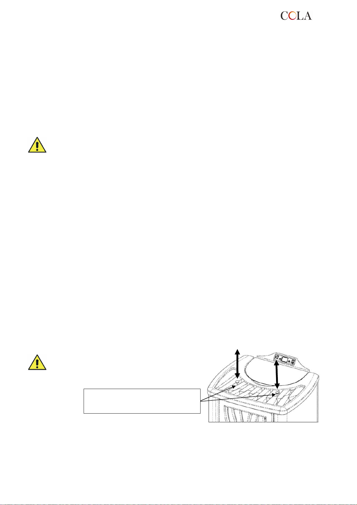
low position.
5.4 Cleaning the fume extractor and combustion chamber
The combustion chamber must be cleaned at least once a year, removing all combustion residuals from the internal
fume pipes and flueways. To carry out this operation, it is necessary to remove the stove top cover, the heating
chamber cover and the bottom inspection door, undoing the relevant fixing screws, then clean the turbulators and
internal fume pipes.
Also, make sure to clean the fume extractor located under the bottom fume manifold accessed through the
inspection door opening.
Every 3-4 months clean the inside walls (insulating-refractory) of the combustion chamber using suitable equipment
(brushes) and replace the vermiculite wall if necessary.
Every 1800 hours of operation, by means of a message 'SERVICE DUE', the stove signals the need for
extraordinary maintenance (not under warranty) to be performed by qualified personnel who will carry out complete
cleaning and reset the message.
Any knocking or forcing can damage the fume extractor, making it noisy during
operation; therefore it is advisable to have this operation carried out by qualified personnel.
5.5 Cleaning the air flow meter
The air flow meter (it measures the flow of combustion air) installed inside the inlet pipe requires periodical internal
cleaning every 3-4 months, using suitable equipment (blowing compressed air or suitable brushes).
5.6 Cleaning the ceramic surfaces
The ceramic tiles are handicraft products and therefore may have minor surface imperfections such as tiny spots or
slight colour differences. It is advisable to use a soft dry cloth to clean the ceramic surfaces; the use of detergents
could highlight any flaws.
5.7 Cleaning the flue - flue connection
The flue connection must be cleaned at least once a year or whenever necessary.
Cleaning requires the suction and removal of the residuals in all the vertical and horizontal sections as well as the
bends from the stove to the flue.
It is advisable to also clean the flue every year, to ensure correct and safe evacuation of fumes.
5.8 Cleaning the exchangers with turbulator-shaker device
The fume ducts inside the heating chamber must be cleaned
at least once a day by operating the two knobs repeatedly with
an upward and downward movement.
Carry out this operation with the stove off and cold.
RH - LH control knobs of the turbulatorshaker device in heating stove operation
TERMO-POWER
68
Page 69
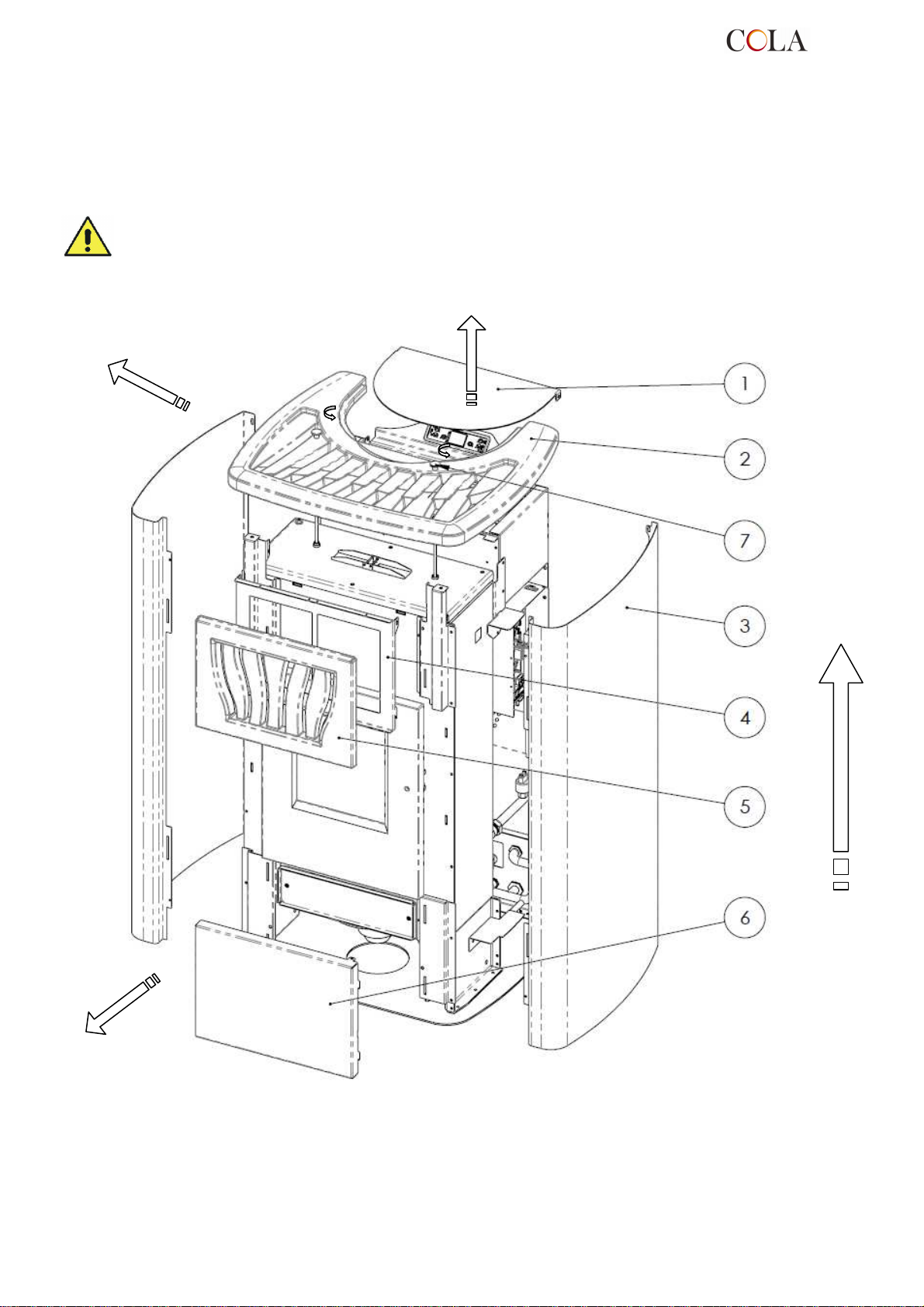
Key:
6 MAINTENANCE
6.1 Introduction
Operations on the internal parts of the stove must be carried out by qualified personnel. Contact the nearest
authorised service centre.
Make sure the stove is unplugged and cold before carrying out any work on it.
6.2 Removing the TERMO POWER cladding
1 - Pellet hopper door
2 - Majolica cover
3 - Side panel
4 - Top front panel support
5 - Majolica top front panel
6 - Bottom front panel
7 - Extensions with knob for turbulators
TERMO-POWER
69
Page 70
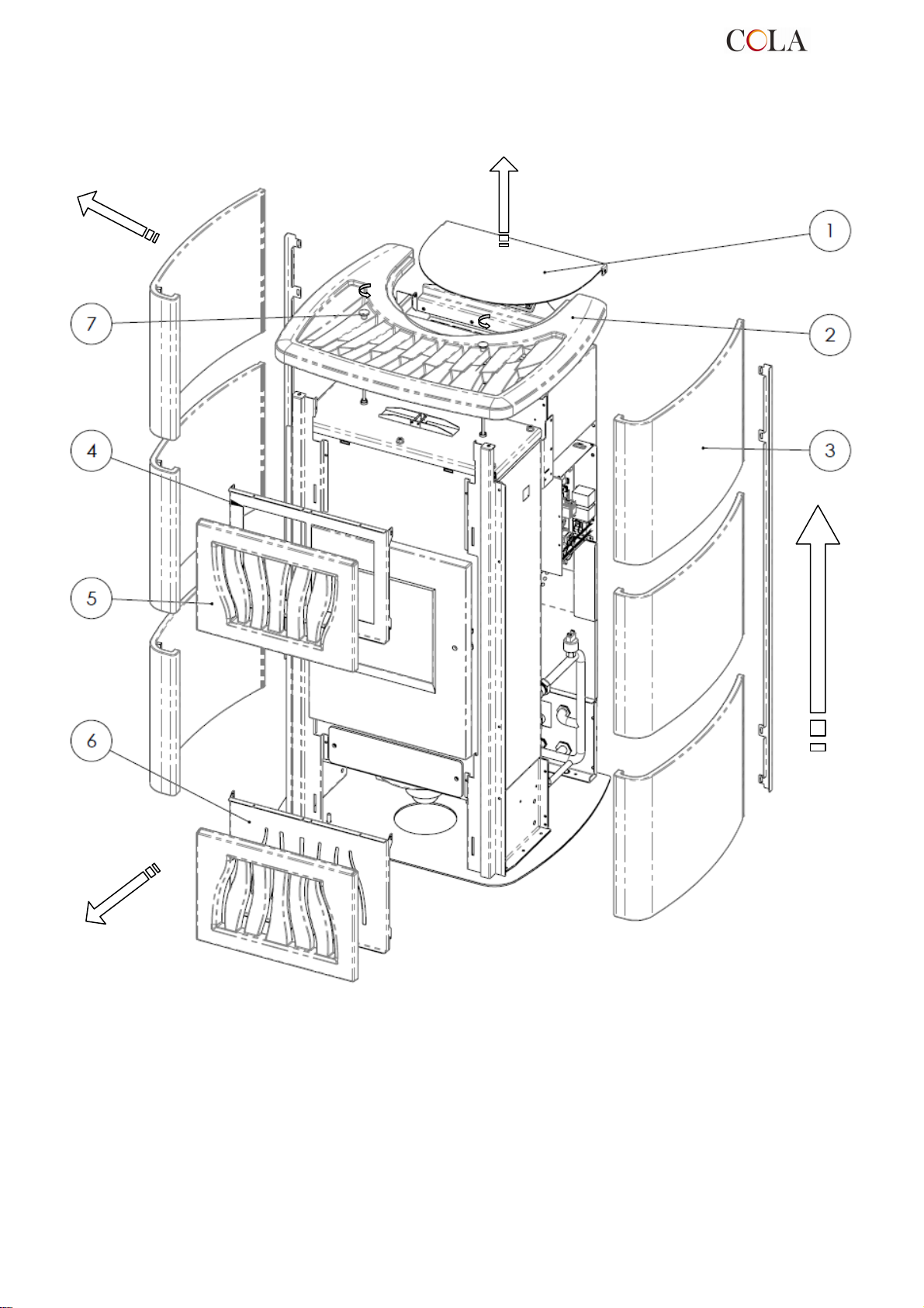
Key:
6.3 Removing the TERMO POWER LUX cladding
1 - Pellet door
2 - Majolica cover
3 - Side majolica
4 - Top front panel support
5 - Majolica top-bottom front panels
6 - Bottom front panel support
7 - Extensions with knob for turbulators
TERMO-POWER
70
Page 71
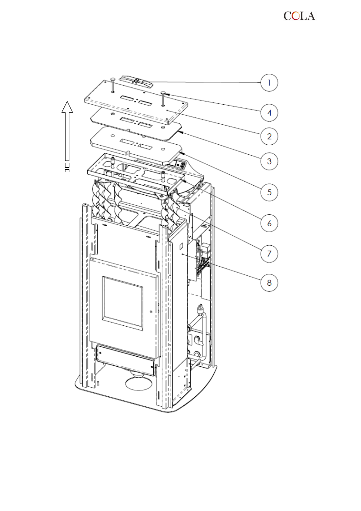
Key:
6.4 Stove internal parts
1 - Safety valve
2 - Heating chamber cover
3 - Isolcart protection
4 - Knob for shaking turbulators
5 - Vermiculite protection
6 - Cover bottom frame
7 - Turbulators
8 - Heating chamber
Exploded view of TERMO-POWER stove combustion chamber and parts
TERMO-POWER
71
Page 72
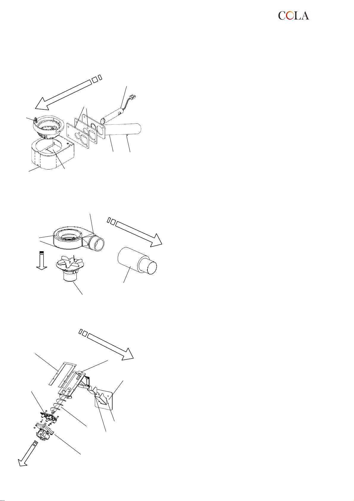
Key:
Key:
Key:
Exploded views of:
1 - Brazier assembly
2 - Fume extractor assembly
3 - Auger assembly
6
1
2
3
5
1 - Brazier
2 - Welded brazier holder
3 - Internal smoke baffle
4 - Combustion air welded inlet pipe assembly
5 - Electrical element
4
7
6 - Seals
7 - Venturi meter
1
2
4
3
1
8
7
2
1 - Fume extractor volute
2 - Thermal seal
3 - Fume extractor motor
4 - Fume exhaust pipe
1 - Conveyor - hopper seal
2 - Gearmotor support flange
3 - Gearmotor
4 - Auger
5 - Seal for chute
6 - Pellet chute
7 - Conveyor-chamber seal
8 - Pellet conveyor
4
3
6
5
TERMO-POWER
72
Page 73
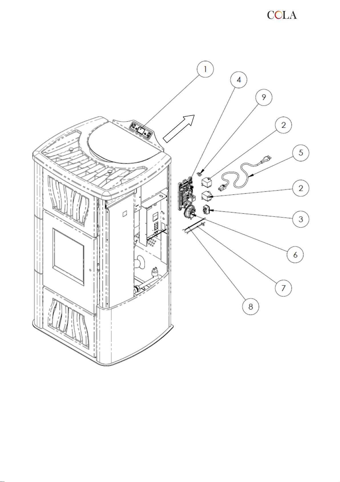
Key:
6.5 Electrical components
1 - Control panel model F047
2 - Safety thermostat
3 - ON-OFF switch with fuses
4 - Electronic board
5 - Power cable
6 - Vacuum switch
7 - Fume probe
8 - Room probe
9 - Serial connection
TERMO-POWER
73
Page 74
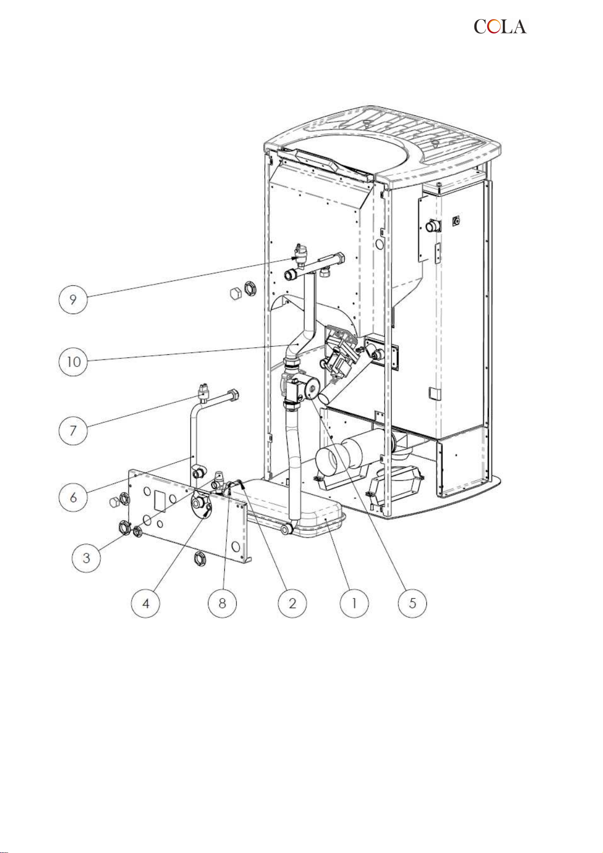
Key:
6.6 Plumbing components
TERMO-POWER
1 - Membrane expansion tank
2 - System drain cock
3 - Safety valve
4 - System filling connection
5 - Circulating pump
6 - Return pipe
7 - Pressure transducer
8 - Expansion tank connection
9 - Air venting valve
10 - Delivery pipe
74
Page 75

The electrical element is faulty,
dirty or not correctly positioned.
7 TROUBLESHOOTING
7.1 Alarm management
Alarms are indicated by an acoustic signal (if activated) and a message on the control panel.
In case of an alarm, shut down the stove, eliminate the cause and restart the stove according to the normal
procedure described in this manual.
Every alarm status causes immediate stove shutdown.
The alarms, with causes and cures, which can appear on the control panel are listed below:
ALARMS - MESSAGES
Signalling Fault Possible causes Cures
-Turn the stove OFF by
AL 1
POWER
FAILURE
-The stove does not start.
-No power during the lighting
stage.
pressing the button P4 and
repeat the lighting procedure.
-Other reinstatement
operations must be carried
out by a service centre.
AL 2
FUME
PROBE
AL 3
HOT FUMES
AL 4
FAN FAIL
AL 5
NO IGNITION
AL 6
NO PELLETS
-Occurs in case of a fume
temperature probe fault.
-The shutdown procedure is
activated.
-Occurs if the fume probe
detects a fume temperature
above 280°C.
-The shutdown procedure is
activated.
-Occurs when the exhaust fan
is faulty.
-The shutdown procedure is
activated.
-No flame in ignition stage.
-The shutdown procedure is
activated.
-Brazier not fed with pellets.
-Faulty probe
-The probe is disconnected
from the board.
-Faulty tangential fan.
-No power to tangential fan.
-Too many pellets.
-The fume fan is blocked.
-Faulty speed control sensor.
-No power to fume fan.
-The pellet hopper is empty.
-
-Pellet load setting incorrect.
-The pellet hopper is empty.
-The pellet feed gearmotor has
to adjust.
-The gearmotor does not feed
pellets.
-Reinstatement operations
must be carried out by a
service centre.
-Adjust the pellet flow.
-Other reinstatement
operations must be carried out
by a service centre.
-Reinstatement operations
must be carried out by a
service centre.
-Check pellets in hopper.
-Check the lighting
procedures.
-Other reinstatement
operations must be carried
out by a service centre.
-Check pellets in hopper.
-Adjust the pellet flow
-Other reinstatement
operations must be carried
out by a service centre.
AL 7
THERMAL
SAF
TERMO-POWER
-Occurs in case of cutting in of
auger duct temperature or
heating chamber water
temperature safety thermostat.
-The system is stopped.
-The safety thermostat has
detected a temperature above
the setting threshold due to
overheating of the bottom part
of the hopper or the heating
chamber water, blocking
gearmotor operation.
75
-Check the cause of excessive
overheating.
-Reset the relevant safety
thermostat by pressing the
reset button.
Page 76

The Manufacturer reserves the right to make t
echnical or aesthetic changes to the products at any time without notice.
-Check cleanness of the fume
duct and combustion
chamber.
-Check hermetic closing of the
door.
-Check closing of the
overpressure valves.
-Other reinstatement
operations must be carried out
by a service centre.
-Check cleanness of the fume
duct and combustion
chamber.
-Check hermetic closing of the
door.
-Check closing of the
overpressure valves.
-Other reinstatement
operations must be carried out
by a service centre.
-Check the cause of the
problem, restoring the circuit
pressure by bringing it to the
normal operating value.
-Reinstatement operations
must be carried out by a
service centre.
-Reinstatement operations
must be carried out by a
service centre.
AL 8
NO NEG
PRESS
AL 9
INSUFF
DRAUGHT
AL E
WATER
PRESSURE
AL b
AUG TRIAC
ERROR
AL c
WATER
PROBE
-In the work stage the stove
detects a pressure below the
vacuum switch setting
threshold.
-The system is stopped.
-Appears when the
combustion air flow is below a
certain threshold.
-Occurs when the water
pressure does not come within
the values for correct
operation.
-The system is stopped.
-Occurs when the gearmotor
works continuously and for
more than 60 sec.
-The system is stopped.
-Occurs in case of a water
temperature probe fault.
-The shutdown procedure is
activated.
-The combustion chamber is
dirty.
-The fume duct is obstructed.
-The fire door is not closed.
-The overpressure valves are
open-stuck.
-Faulty vacuum switch.
-The combustion chamber is
dirty.
-The fume duct is obstructed.
-The fire door is not closed.
-The overpressure valves are
open-stuck.
-Faulty air flow meter.
-Occurs when the pressure
transducer on the water circuit
detects a pressure below or
above the fixed limits.
-The controller detects a faulty
gearmotor control relay
(contacts stuck).
-Faulty probe
-The probe is disconnected
from the board.
AL d
HOT
WATER
WAITING
COOL
AIR FLOW
METER
FAILURE
FROST RISK
SERVICE
DUE
-Occurs when the water
temperature has exceeded the
fixed limits.
-The system is stopped.
-Occurs on relighting the stove
immediately after having shut
it down.
-Occurs when the air flow
meter is disconnected.
-Occurs when the water
temperature falls below a
certain value.
-Occurs when the stove has
exceeded 1800 hours of
operation since the previous
servicing.
-Occurs when the temperature
probe in the heating chamber
detects a value above 92°C.
-Reset attempt in shutdown
stage with stove hot in cooling
stage.
-The controller does not detect
the quantity of combustion air
and does not shut down the
stove; it only excludes the air
flow meter functions.
-The stove control detects the
water temperature below 6°C
and displays a message.
-Extraordinary maintenance
notice.
-Check the cause of the
problem, restoring the
temperature by bringing it to
the normal operating value.
-Alarm reset is possible only
after shutdown.
-Reinstatement operations
must be carried out by a
service centre.
-The pump starts in order to
move the water inside the
heating circuit.
- Monitor the water
temperature so that it does not
fall below 0°C.
- Cleaning - extraordinary
maintenance and
reinstatement operations must
be carried out by a service
centre.
The drawings, measurements, diagrams and any other configurations are given only by way of example.
TERMO-POWER
76
Page 77
8 ENCLOSURES
CE MARKING INFORMATION
COLA
2012
EN 14785 : 2006
Min. safety distance from flammable materials
rear - right/left side - floor
CO emissions at 13% O2 in fumes :
Dust emissions at 13% O2 in fumes : Pnom : 10.7 mg/m3
Max. water operating pressure : 2 bar
Flue gas temperature :
Nominal and reduced heat output
Efficiency
Types of fuel
Electrical power
Rated voltage
Rated frequency
Wood pellet-burning domestic heating appliances
Ref. TERMO POWER – TERMO POWER LUX
: 200 – 200 - 0 mm
Pnom : 0,005 %
Pred : 0,01 %
P.nom. 119.3 °C
P.red. 58.9 °C
Pnom : total 23.5 kW
water heat 20.1 kW
space heat 3.4 kW
Pred : total 7.1 kW
water heat 5.6 kW
space heat 1.44 kW
Pnom : 93.6 %
:
Pred : 95.2 %
Wood pellets
:
420 W – 140 W
:
230 V
:
50 Hz
:
TERMO-POWER
77
Page 78

1 RECOMMANDATIONS GÉNÉRALES
1.1 Introduction
1.2 Comment utiliser ce manuel
1.3 Règles de sécurité
1.4 Description technique
1.5 Combustible et usage prévu
1.6 Accessoires fournis
1.7 Normes de référence
1.8 Plaque d’identification
1.9 Mise hors service du poêle
1.10 Demande d’intervention et de pièces
détachées
2 TRANSPORT ET INSTALLATION
2.1 Emballage, manutention, expédition et
transport
2.2 Lieu d'installation, mise en place et sécurité
anti-incendie
2.3 Prise d'air
2.4 Évacuation des fumées de combustion
2.4.1 Types d'installations
2.5 Contrôle de la position du brasier et des
turbulateurs
2.6 Branchement électrique
2.7 Schéma électrique
2.8 Schéma électrique pour installation àzones
2.9 Raccordements hydrauliques
2.10 Première intervention
SÉCURITÉ
3.1 Distance de sécurité par rapport aux
matériaux combustibles.
3.2 Sécurité pour l'évacuation des fumées
3.3 Sécurité en cas de surpression dans la
chambre de combustion
3.4 Surchauffe-thermostat de sécurité
température réservoir granulés
3.5 Sécurité contre le retour de flamme sur le
canal d'alimentation en granulés
3.6 Dispositif électrique de protection contre les
surtensions
3.7 Sécurité en cas de coupure de courant
3.8 Sécurité contre la surpression du circuitd'eau
3.9 Dysfonctionnement du ventilateur d'extraction
des fumées
4 UTILISATION DU POÊLE
4.1 Introduction
4.2 Description du tableau de commande
4.3 Allumage
4.3.1 Contrôle avant l'allumage
4.3.2 Mise en marche
4.4 Fonctionnement
4.4.1Modification du préréglage de la température
ambiante
4.4.2Modification du préréglage de la température de
l'eau
4.4.3 Remise en marche à partir du mode VEILLE
(STAND-BY)
4.4.4 Nettoyage du brasier
4.4.5 Eau chaude sanitaire avec échangeur rapide.
4.4.6 Eau chaude sanitaire avec un préparateur d’eau
chaude.
4.4.7Installation avec un ballon d’accumulation
4.5 Extinction
TERMO-POWER
78
4.6 Menu
4.6.1 menu 01 – réglage des ventilateurs
4.6.2 menu 02 – réglage de l'horloge
4.6.3 menu 03 – activation du chrono
4.6.4 menu 04 – choix de la langue
4.6.5 menu 05 – mode veille (stand-by)
4.6.6 menu 06 – alarme sonore (buzzer)
4.6.7 menu 07 – chargement initial
4.6.8 menu 08 – état du poêle
4.6.9 menu 09 – réglages du technicien
4.7 Télécommande
4.7.1 remplacement de la pile
4.8 Thermostat – chronothermostat externe
4.9 Période d'inactivité (fin de saison)
5 NETTOYAGE DU POÊLE
5.1 Nettoyage du brasier
5.2 Nettoyage du cendrier
5.3 Nettoyage de la vitre
5.4 Nettoyage de l'extracteur de fumée
et de la chambre de combustion
5.5 Nettoyage du venturi
5.6 Nettoyage des céramiques (modèles en
céramique)
5.7 Nettoyage du conduit de raccordement
- conduit de fumée
5.8 Nettoyage des échangeurs avec le
dispositif de secouage des turbulateurs
6 ENTRETIEN
6.1 Introduction
6.2 Dépose de l'habillage T-POWER
6.3 Dépose de l'habillage T-POWER LUX
6.4 Composants internes du poêle
6.5 Composants électriques
6.6 Composants hydrauliques
7 RECHERCHE DES PANNES
8 ANNEXES
7.1 Gestion des alarmes
8.1 Informations relatives au marquage CE
Page 79
1 RECOMMANDATIONS GÉNÉRALES
1.1 Introduction
Cher Client !
Nous vous remercions de la confiance que vous nous avez accordée en achetant ce produit. Nous vous invitons à
lire et à suivre attentivement les conseils fournis par ce manuel d’installation, d'utilisation et d'entretien pour exploiter
au mieux les qualités de cet appareil.
1.2 Comment utiliser ce manuel
La société COLA s.r.l. se réserve d'apporter des modifications techniques ou esthétiques à ses produits à n'importe quel moment
et sans préavis.
Les opérations d'installation, d'utilisation et d'entretien du poêle doivent satisfaire les exigences de ce manuel, des normes
européennes, nationales et locales.
Toutes les configurations, les dessins, les mesures et les schémas sont fournis à titre d'exemple.
Ce manuel constitue une partie intégrante et essentielle du produit ; si l'appareil doit être vendu ou transféré à un autre
propriétaire ou s'il doit être installé à un autre endroit, s'assurer que le manuel accompagne l'appareil afin qu'il puisse être
consulté ultérieurement à tout moment.
En cas de perte ou de détérioration de ce manuel, demander une copie de celui-ci au centre d'assistance technique autorisé afin
qu'il reste toujours avec l'appareil.
Ce symbole indique la présence d’un message important auquel prêter une attention particulière car la
non observation des instructions peut entraîner de sérieux dommages au poêle et aux personnes.
Une information nécessitant une attention particulière est mise en évidence par un texte écrit en
1.3 Règles de sécurité
- Lire attentivement ce manuel avant l'installation, l'utilisation et l'entretien du poêle.
- L'installation, les raccordements électriques, l'essai et l'entretien doivent être effectués par un professionnel
qualifié et/ou agréé.
- Raccorder le poêle au conduit de fumée à l'aide d'un terminal qui puisse être inspecté ; le raccordement à plusieurs
appareils peut se faire uniquement dans le respect des normes locales et autorisé par l'organisme de contrôle du
conduit de fumée.
- Raccorder le poêle, de l'extérieur à la bouche d'aspiration, à l'aide d'un tuyau ou d'une prise d’air.
- Raccorder le poêle à une prise de courant homologuée de 230 V- 50 Hz.
- Pour le modèle TERMO, raccorder l'appareil à l'installation de chauffage ; ce modèle ne peut en aucun
cas peut être utilisé sans raccordement hydraulique et sans charge en eau interne de la chambre thermique.
- Vérifier que l’installation électrique et les prises puissent supporter la consommation maximale
de l’appareil figurant sur l’étiquette et sur le manuel.
- Avant de procéder aux opérations d'entretien, débrancher le poêle et attendre qu'il soit froid.
- Ne pas utiliser de liquides ou substance inflammables pour allumer le poêle ou raviver la flamme :
l'embrasement des granulés se fait automatiquement lorsque le poêle est allumé.
- Le poêle à granulés doit être alimenté exclusivement par des granulés de bois
dont les caractéristiques sont décrites dans ce manuel.
- Le poêle à granulés ne doit pas être utilisé comme incinérateur.
- Ne jamais obstruer les bouches d'entrée de l'air comburant et de sortie des fumées.
- Il est absolument interdit de manipuler des substances facilement inflammables ou explosives à proximité du
poêle pendant son fonctionnement.
- Ne pas enlever la grille de protection du réservoir des granulés.
- Éviter le fonctionnement du poêle avec la porte du foyer ouverte et/ou la vitre en mauvais état ou brisée.
- Pendant le fonctionnement, la chaleur dégagée par la combustion des granulés surchauffe les surfaces
extérieures du poêle telles que la porte du foyer, la poignée et le tuyau d'évacuation des fumées. Éviter donc
d'entrer en contact avec ces parties sans porter des protections appropriées.
- Toujours tenir à une distance de sécurité suffisante tous les objets sensibles à la chaleur et/ou inflammables.
- Nettoyer régulièrement le foyer à chaque allumage ou chargement de granulés.
- Éviter la formation de fumée ou d'imbrûlés de combustion pendant l'allumage et/ou le fonctionnement normal,
- Faire nettoyer régulièrement le conduit et les déflecteurs de fumée à l’intérieur de la chambre de combustion par
un technicien qualifié.
- Informer les enfants et les visiteurs des dangers décrits ci-dessus.
- En cas d'anomalie de fonctionnement, le poêle peut être rallumé seulement après avoir éliminé la cause de l'inconvénient.
- Toute modification ou adaptation non prévue et/ou tout remplacement non autorisé de pièces non originales du
- N'utiliser que des pièces de rechange d'origine.
«caractères gras».
normal, l’accumulation excessive de granulés imbrûlés dans le brasier doit être retirée à la main avant d'effectuer
un nouvel allumage.
poêle peut représenter un danger pour les personnes et dégage le constructeur de toute responsabilité civile et pénale.
La société Cola s.r.l. décline toute responsabilité pour les inconvénients, les ruptures ou les accidents
causés par l'inobservation ou l'inapplication des indications contenues dans ce manuel.
TERMO-POWER
79
Page 80

1.4 Description technique
Le poêle est alimenté exclusivement avec des granulés de bois et peut facilement être raccordé à une installation de
chauffage. Les systèmes de contrôle automatiques dont il est pourvu assurent un rendement thermique optimal et
une combustion complète. Des systèmes de sécurité garantissent des conditions de sécurité pour l'utilisateur et la
fiabilité des composants du poêle.
Si le poêle est installé conformément aux textes réglementaires et règles de l'art en vigueur, il fonctionnera dans
n'importe quelles conditions climatiques extérieures, mêmes critiques (vent fort, gel, etc.), car les systèmes de
sécurité dont il est équipé arrêteront son fonctionnement (extinction).
Structure
Chambre de combustion acier
Puissance thermique nominale - réduite
Puiss. thermique de production H2O P. nom.- P. réd.
Puis.thermique pour réchauffer l'air P. nom.- P. réd.
Consommation horaire P. nom.- P. réd.
Rendement P. nom.- P. réd.
Température de sortie des fumées P. nom.- P. réd.
Émissions de CO à 13% O2
Débit gaz de combustion
Émissions de poussières à 13% O2
Tirage minimum
Tuyau d'évacuation des fumées
Tuyau de prise d'air
acier et fonte
P.nom 23.5 kW P
P.nom 20.1 kW P
P.nom 3.4 kW P
P.nom. 5.1 kg./h* P.
P.nom. 93.6 % P.
P.nom. 119.3 °C P.
P.nom. 0.005 % P.
P.nom. 13.9 g/s P.
P.nom. 10.7 mg/m3
10 Pa
Ø 100 mm
Ø 50 mm
réd
. 7.1 kW
réd
. 5.6 kW
réd
1.44 kW
réd
.1.52 kg./h.*
réd
. 95.2 %
réd
. 58.9 °C
réd
. 0.01 %
réd
. 7.6 g/s
Alimentation électrique
Consommation électrique
Distance minimale de sécurité à l'arrière, sur le côté
droit, sur le côté gauche, du sol
Capacité du vase d'expansion
Capacité de la chambre de combustion
Pression max. de fonctionnement
Dimensions (mm)
Poids du poêle
Capacité du réservoir à granulés
Volume max. de chauffe
* La consommation de granulés varie en fonction du type de granulés utilisés.
** En considérant 35 W/h par m
3
. Le besoin énergétique de l'édifice peut varier en fonction
230V/50 Hz
420 W max. à l'allumage
140 W pendant le fonctionnement normal
200 – 200 – 0 mm
8 litri
Litri 23
2 bar
H x L x P = 1241 x 700 x 627 mm
212 kg - T-POWER
254 kg - T-POWER LUX
48 kg
530 m3 **
de l'isolation, du type de construction et de la zone climatique .
TERMO-POWER
80
Page 81
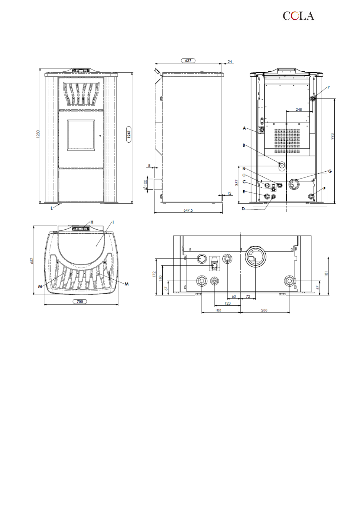
Dimensions du poêle chaudière à granulés TERMO-POWER – TERMO-POWER LUX
Légende :
A - Raccordement câble électrique
B - Aspiration d'air comburant
C - Évacuation d'eau en surpression (1/2" F - 3 bars)
D - Raccordement réseau eau de ville
E - Retour installation (1" M )
F - Départ installation (1" M )
G - Raccordement tuyau d'évacuation des fumées, diamètre 100 mm
H - Tableau de commande mod.F047
I - Couvercle de réservoir à granulés
L - Pieds (Vérins) réglables
M - Bouton de secouage des turbulateurs
N - Départ eau sanitaire en option ( 3/4" M - POMPE – 1/2"M - ÉCHANGEUR )
O - Retour eau sanitaire en option ( 3/4" M - POMPE – 1/2"M - ÉCHANGEUR )
P - Raccord supplémentaire départ sans pompe (1" M )
Dimensions du poêle Termo-POWER
TERMO-POWER
81
Page 82
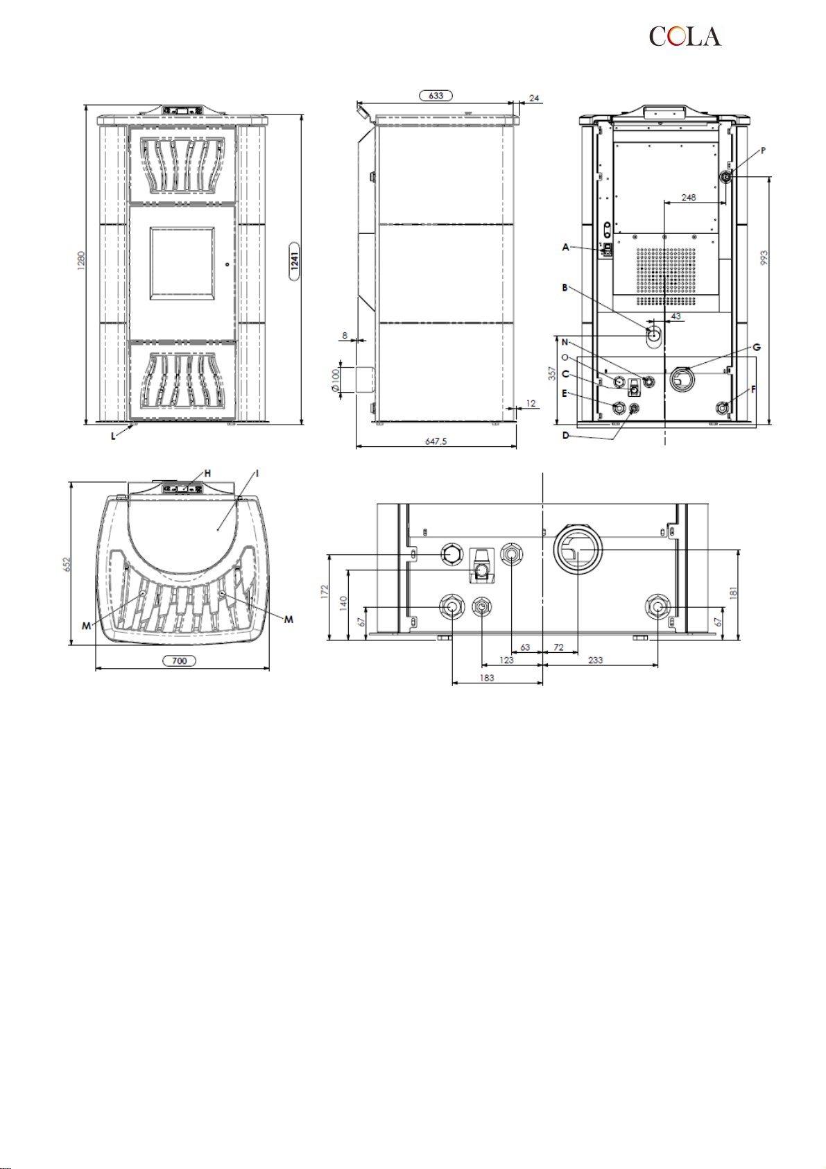
Légende :
A - Raccordement câble électrique
B - Aspiration d'air comburant
C - Évacuation d'eau en surpression (1/2" F - 3 bars)
D - Raccordement réseau eau de ville
E - Retour installation (1" M )
F - Départ installation (1" M )
G - Raccordement tuyau d'évacuation des fumées, diamètre 100 mm
H - Tableau de commande mod.F047
I - Couvercle de réservoir à granulés
L - Pieds (Vérins) réglables
M - Bouton de secouage des turbulateurs
N - Départ eau sanitaire en option ( 3/4" M - POMPE – 1/2"M - ÉCHANGEUR )
O - Retour eau sanitaire en option ( 3/4" M - POMPE – 1/2"M - ÉCHANGEUR )
P - Raccord supplémentaire départ sans pompe (1" mâle)
Dimensions du poêle Termo-POWER LUX
TERMO-POWER
82
Page 83
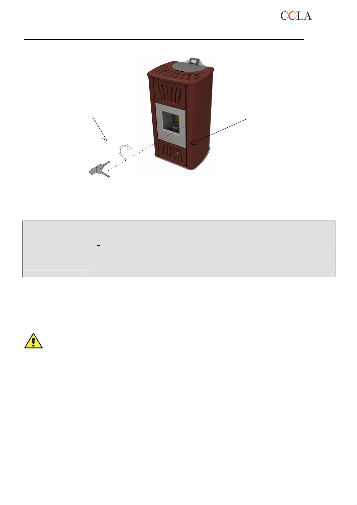
ignée fournie et tourner en sens
fermeture
Ouverture - fermeture de la porte de foyer du poêle chaudière à granulés TERMO POWER
Poignée d'ouvertureporte de foyer ;
- Ouverture : sens anti-horaire
- Fermeture : sens horaire
Pour ouvrir la porte, insérer la
po
horaire.
1.5 Combustible et usage prévu
Les poêles à granulés fonctionnent exclusivement avec des granulés (pastilles) d'essences de bois différentes,
conformément à la norme DIN plus 51731 ou UNI EN14961-2 ou Ö-Norm M 7135, ayant les caractéristiques
suivantes :
Pouvoir calorifique : min. 4.8 kWh/kg (4180 kcal/kg)
Densité : 680-720 kg
Humidité : max. 10% de son poids
Diamètre : 6 +0,5 m
Taux de cendres max. 1,5% de son poids
Longueur : min. 6 mm- max .30 mm
Composition : 100% bois non traité de l’industrie du bois ou post consommation sans adjonction de substances
liantes et sans écorce conforme aux normes en vigueur
Conditionnement : dans des sacs confectionnés avec des matières éco-compatibles ou biodégradables ou en papier
Le réservoir à granulés se trouve à l’arrière du poêle. Le couvercle du réservoir est placé dans la partie supérieure
du poêle et le chargement se fait manuellement uniquement poêle éteint en faisant attention à ne pas faire sortir le
sac de granulés.
L'utilisation de granulés de bois ayant des caractéristiques différentes de celles des granulés utilisés pour le test lors
du premier allumage implique un nouvel ajustement des paramètres de chargement des granulés dans le poêle.
Noter que cette intervention n'est pas couverte par la garantie.
- Les granulés doivent être stockés dans un lieu sec et protégé contre l'humidité.
- En vue d'un fonctionnement efficace et régulier du poêle, il n’est pas possible de charger manuellement
les granulés ou d'autres combustibles dans le foyer.
- Éviter le chargement de combustibles non conformes dans le réservoir.
- Éviter le chargement de corps étrangers, tels que récipients, boîtes, sachets, métaux etc.., dans le
réservoir.
- L'utilisation de granulés de qualité médiocre et non conforme détériore et compromet le bon
fonctionnement du poêle, ce qui entraîne l'annulation de la garantie et dégage le constructeur
de toute responsabilité.
1.6 Accessoires fournis
La fourniture comprend :
câble d'alimentation électrique ;
manuel d’installation, utilisation et entretien ;
clé d'ouverture - de fermeture ;
télécommande.
1.7 Normes de reference
Norme UNI 10683:2005 : Elle fixe les exigences essentielles concernant l'installation des générateurs de chaleur à bois
ou à d'autres biocombustibles solides ;
TERMO-POWER
83
Page 84
Tension d'alimentation
Norme UNI EN14785:2006 : Elle fixe les exigences essentielles relatives à la conception, à la fabrication, à la sécurité, aux
performances (rendement et émissions), aux instructions et aux marquages, ainsi qu'aux
méthodes d'essai correspondantes pour les essais de type d'appareils fonctionnant aux
granulés de bois ;
Norme CEI EN 60335-1 : Appareils électrodomestiques et analogues - Sécurité - Partie 1 ;
Norme CEI EN 60335-2-102 : Appareils électrodomestiques et analogues - Sécurité - Partie 2 ;
Norme CEI EN 55014-1 : Compatibilité électromagnétique – Exigences pour les appareils électrodomestiques, outillages
électriques et appareils analogues - Partie 1 : Émission ;
Norme CEI EN 55014-2 : Compatibilité électromagnétique – Exigences pour les appareils électrodomestiques, outillages
électriques et appareils analogues - Partie 2 : Immunité ; Norme famille de produits ;
Norme CEI EN 61000-3-2 : Limites pour les émissions de courant harmonique (courant appelé par les appareils inférieur ou
égal à 16 A par phase) ;
Norme CEI EN 61000-3-3 : Limitation des variations de tension, des fluctuations de tension et du papillotement dans les
réseaux publics d'alimentation basse tension, pour les matériels ayant un courant assigné
inférieur ou égal à 16 A par phase et non soumis à un raccordement conditionnel ;
Norme CEI EN 62233 : Méthodes de mesure des champs électromagnétiques des appareils électrodomestiques et
similaires en relation avec l'exposition humaine.
Normes DIN plus 51731 – UNI EN14961-2 - Ö-Norm M 7135 : Normes relatives aux spécifications et à la classification des
granulés de bois.
1.8 Plaque d’identification
La plaque d'identification est fixée sur la face intérieure du couvercle du réservoir à granulés ou à l'arrière du poêle.
La plaque porte les indications suivantes :
Modèle
►
Numéro de fabrication
►
Type de combustible
►
Puissance thermique nominale - réduite
►
Consommation à la P.nom.et P.réd.
►
Température à la Pnom et Préd
►
Rendement thermique
►
►
Consommation électrique
►
Dimension du tuyau d'évacuation des gaz
►
Dimensions du tuyau d'aspiration
►
Tirage minimum
►
Dimensions hors tout du poêle
►
Dimensions des raccords hydrauliques
►
Distance de sécurité par rapport aux matériaux inflammables
►
Poids
►
1.9 Mise hors service du poêle
A partir du moment où le poêle n’est définitivement plus utilisé, débrancher l’alimentation électrique et vider
complètement le réservoir à granulés. Pour procéder à l’évacuation du poêle, il est nécessaire de prévoir un
emballage solide et adapté. Il faut ensuite contacter les organismes locaux afin de connaitre les règles et normes en
vigueurs pour l’évacuation du matériel, ou restituer au revendeur du nouveau produit similaire, l’appareil usagé.
Aux sens de l’article.13 du Décret législatif n°151 du 25 Juillet 2005 de réalisation de la Directive 2002/96/CE du
23 Février 2003 sur les Rebus des Appareillages Electriques et Electroniques relatifs aux mesures et procédures
visant à prévenir la production des déchets des appareillages électriques et électronique, dénommée RAEE.
Promouvoir la réutilisation, le recyclage et autres formes de récupération de façon à réduire la quantité de
déchets en améliorant leur écoulement par l’intervention des différentes parties participant au cycle de vie de tels
produits.
Le symbole barré de la boite de tri indiqué sur l’étiquette du produit, indique que le produit à la fin de sa vie, doit être
évacué séparément des autres déchets.
1.10 Demande d’intervention et de pièces détachées
Pour toute demande d'intervention et/ou de pièces détachées, contacter son revendeur, le revendeur de zone ou le
centre d'assistance agréé le plus proche, en précisant toujours : modèle du poêle, numéro de série, date d'achat,
liste des pièces de rechange, les anomalies de fonctionnement constatées.
- Les interventions sur les composants doivent être effectuées par un personnel agréé et/ou qualifié.
- Avant de procéder aux opérations, s'assurer que toutes les connexions électriques sont débranchées et
que le poêle est froid.
- N'utiliser que des pièces de rechange d'origine.
2 TRANSPORT ET INSTALLATION
2.1 Emballage, manutention, expédition et transport
Le poêle peut être soulevé à l'aide d'un chariot élévateur en introduisant les fourches d'une longueur adéquate aux
endroits prévus à cet effet sur la palette en bois. S'assurer que la capacité des appareils utilisés pour le levage et le
transport est suffisante pour supporter le poids du poêle indiqué sur la plaque d'identification et dans ce manuel.
Éviter de passer dans des zones où la chute de la charge pourrait représenter un danger.
Déballer le poêle et le poser à l’endroit choisi en veillant à sa conformité avec la commande et en suivant les
illustrations des pages suivantes.Il est recommandé de poser délicatement le poêle au sol pour éviter tout choc
éventuel, et de l'installer dans la zone prévue ; s'assurer également que le plancher est assez solide pour supporter
le poids du poêle ; dans le cas contraire, consulter un technicien spécialisé.
L’élimination ou le recyclage de l’emballage est à la charge de l’utilisateur final en conformité avec la réglementation
locale en vigueur.
TERMO-POWER
84
Page 85
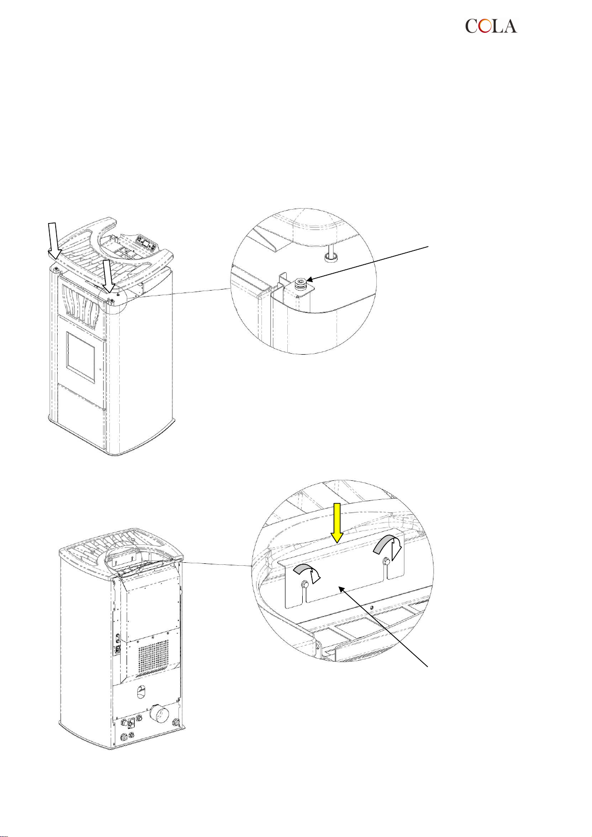
Tampon
DÉTAIL A
DÉTAIL B
2.1.1
Montage du couvercle TERMO POWER
Le couvercle est soigneusement emballé et se trouve dans la caisse carton contenant le poêle :
- déballer soigneusement le couvercle, contrôler l'état apparent de celui-ci et, si aucun endommagement n'est
décelé, le monter au terme des opérations de mise en place du poêle, en procédant comme suit :
X - placer le couvercle en respectant l'emplacement, sur le poêle, des 2 tampons antivibratoires (détail A) permettant
son centrage.
Y - bloquer le couvercle en position en fixant l'arrêt central sans forcer comme le montre la figure.
X
Y
ÉCHELLE 1:2
Arrêt
ÉCHELLE 1:2
TERMO-POWER
85
Page 86
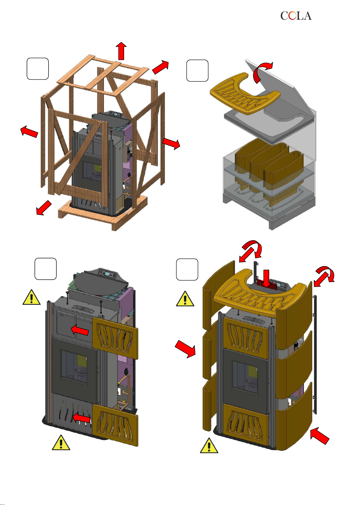
X
4
4
2.1.2
Montage des faïences TERMO POWER
A
C
B
X
D
TERMO-POWER
86
Page 87
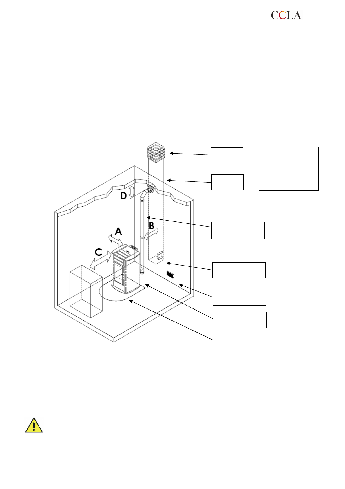
2.2 Lieu d’installation, mise en place et sécurité anti-incendie
La pièce dans laquelle le poêle est installé doit être suffisamment aérée pour assurer une bonne évacuation en cas
de fuite éventuelle de fumée de combustion.
L’appareil peut fonctionner dans une habitation ayant une température minimum de 0 °C : il dispose d'u ne fonction
antigel qui amorce la pompe de chauffage dès que la température de l’eau du circuit descend en dessous de 6 °C,
afin de protéger la chambre de combustion et le circuit de chauffage-sanitaire. La fonction antigel est disponible
uniquement sur les poêles à alimentation électrique.
Pour éviter tout risque d'incendie, protéger les structures autour du poêle de la chaleur. Une plaque de sol en acier
ou en verre trempé doit être prévue pour protéger les parquets ou autres planchers en matière inflammable
(moquette, linoléum, etc.) et doit respecter les distances réglementaires autour du poêle. Si le conduit de fumée doit
traverser des plafonds ou des poutres de bois ou de tout autre matière combustible, celui-ci doit être dûment isolé
selon la réglementation encadrant l'installation du poêle à granulés. Il est toujours conseillé d'installer des
équipements anti-incendie appropriés.
La distance minimale de sécurité devant le poêle pour les objets inflammables est de 1,5 m. Les distances
minimales de sécurité par rapport aux matériaux combustibles doivent être de 0,2 m minimum et doivent en tout cas
correspondre à l'écart au feu indiqué dans le tableau ci-après :
Souche de
cheminée
anti-vent
Conduit de
fumée
Conduit de
raccordement
Trappe de visite sur
le conduit de fumée
Prise d'air murale
min. 100 cm²
Raccord en T muni
de bouchon de visite
A = 200 mm
B = 200 mm
C = 1500 mm
D = 200 mm
Plaque de sol
Chaque installation doit prévoir un espace technique facilement accessible pour effectuer les opérations d'entretien
éventuelles. Le poêle est doté de 4 pieds réglables pour faciliter sa mise en place sur des sols irréguliers. Pour
régler la hauteur du pied, incliner le poêle et tourner le pied jusqu'à obtenir la juste hauteur.
Le poêle est fourni avec une sonde d’ambiance fixée par un collier sur la paroi arrière du poêle.
Nous conseillons son déplacement afin d’améliorer lecture de la température ambiante. La longueur du câble de la
sonde, permet de la déplacer et de la positionner plus haut.
Pour optimiser la lecture de la température ambiante, nous conseillons l’installation d’un thermostat ou appareil
d’ambiance – cf. paragraphe 4.8.
- Il est interdit d'installer le poêle dans les chambres à coucher, les salles de bain et, d'une manière
générale, dans des locaux où est déjà installé un autre appareil de chauffage sans une amenée d'air
indépendante.
- En cas d'installation du poêle sur un parquet (moquette ou linoléum), prévoir une plaque de sol
conformément aux prescriptions du DTU en vigueur.
- Il est toujours conseillé d'installer des équipements anti-incendie appropriés.
- Il est interdit d’installer le poêle dans des ambiances explosives.
TERMO-POWER
87
Page 88
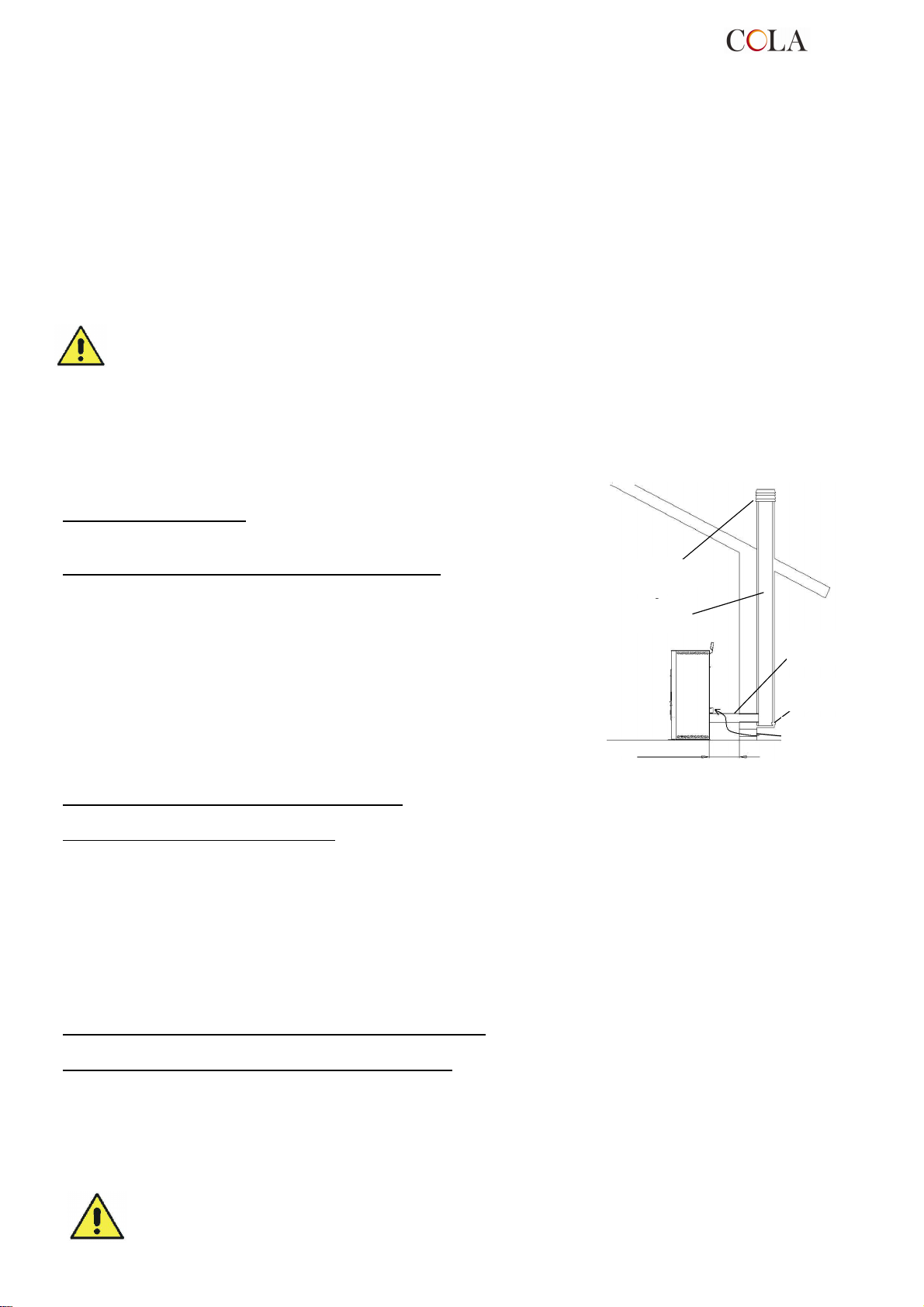
Canna
Comignolo
Presa d’aria
Camera
Distanza min 0.2m
Raccordo
2.3 Prise d’air
Le conduit d'aspiration, ou prise d'air du poêle, a une section circulaire de 50 mm de diamètre et est installé à
l'arrière du poêle.
L’air de combustion peut être :
prélevé directement dans la pièce, à condition de prévoir une prise d'air extérieur murale à proximité du poêle,
►
présentant une surface minimum de 100 cm², convenablement positionnée afin de ne pas être obstruée et
protégée par une grille extérieure ;
prélevé directement de l'extérieur à travers un tuyau de 1,5 m maximum de long et avec diamètre intérieur de
►
50 mm.
2.4 Évacuation des fumées de combustion
Les fumées peuvent être évacuées par un conduit de fumée traditionnel.
- Il est recommandé à l’installateur de vérifier l’efficacité et l’état de la cheminée, ainsi que la conformité à
la réglementation locale, nationale et européenne en vigueur.
-Utiliser impérativement des tuyaux ou conduits et raccords certifiés avec des joints adéquats qui
garantissent l’étanchéité.
-En cas d'incendie, éteindre le poêle, appeler immédiatement les pompiers et éviter toutes tentatives
répétées d'extinction du poêle.
2.4.1 Types d'installations
Voici quelques définitions et règles d'installation d'un conduit de fumée
selon la norme italienne UNI10683 :
CONDUIT DE CHEMINÉE : conduit vertical destiné à collecter et à évacuer
à une certaine hauteur du sol les produits de combustion provenant d'un
seul appareil et, dans les cas autorisés, de plusieurs appareils.
Prescriptions techniques du CONDUIT DE CHEMINÉE :- il doit être
étanche, isolé et calorifugé en fonction de l'usage auquel il est destiné ;
- il doit être le plus droit possible avec des dévoiements dont l'angle de
ceux-ci avec la verticale doit être < 45° ;
- respecter une distance minimale ("écart de feu") avec les matériaux
combustibles de la construction par interposition d'une lame d'air ou
doublage avec des matériaux isolants ;
- il doit avoir de préférence une section interne circulaire, uniforme sur toute
sa hauteur, libre et indépendante ;
- il doit si possible comporter une chambre de visite pour collecter les
matières solides (suies) et les condensats éventuels, située à l'embouchure
Distance minimale 0,2 m
du conduit de raccordement ou carneau.
CARNEAU ou CONDUIT DE RACCORDEMENT : conduit ou élément de raccordement entre l'appareil et le conduit
de fumée, pour l'évacuation des produits de combustion.
Prescriptions techniques du CARNEAU : - il ne doit pas traverser des locaux où l'installation d'appareils de
combustion est interdite ;
- l'usage de conduits métalliques flexibles ou en fibrociment est interdit ;
- l'utilisation d'élément à contre-pente est interdite ;
- le(s) tronçon(s) horizontal(aux) du conduit doit(doivent) avoir une pente minimale de 3% vers le haut ;
- la longueur du tronçon ne doit pas dépasser 3 m minimum ;
- le nombre de dévoiements admis, sans raccord en T, ne doit pas être supérieur à 3 ;
- en cas de dévoiement > 90°, prévoir le montage de 2 coudes maximum d'une allure horizontale ne dépassant
pas 2 m ;
- le conduit de raccordement doit avoir une section uniforme sur toute la longueur et permettre de récupérer la suie.
SOUCHE DE CHEMINÉE (appelée aussi SORTIE DE TOIT) : élément placé au sommet du conduit de fumée ou de
cheminée (sa partie extérieure) servant à évacuer dans l'atmosphère les produits de combustion (les fumées).
Prescriptions techniques de la SOUCHE DE CHEMINÉE : - elle doit avoir une section équivalente à celle du conduit
de fumée ;
- elle doit avoir une section utile non inférieure au double de la section intérieure du conduit de fumée ;
- elle doit empêcher la pénétration de la pluie, de la neige et/ou d'autres corps étrangers dans le conduit de fumée et
garantir en toutes conditions climatiques l'évacuation des produits de combustions (les fumées) ;
- elle doit pouvoir assurer une dilution adéquate des produits et être positionnée en dehors de la zone de reflux ;
- elle ne doit pas comporter de moyens mécaniques d'aspiration.
L'évacuation directe des produits de combustion doit être prévue en toiture et reste interdite vers des
espaces clos même si à ciel ouvert.
Souche
antivento
anti-vent
Conduit de
fumaria
fumée
Conduit de
raccordement
fumi
Chambre
ispezionabile
inspectionnable
Prise d’air
esterna
extérieur min.
min.100 cm
100 cm2
2
TERMO-POWER
88
Page 89
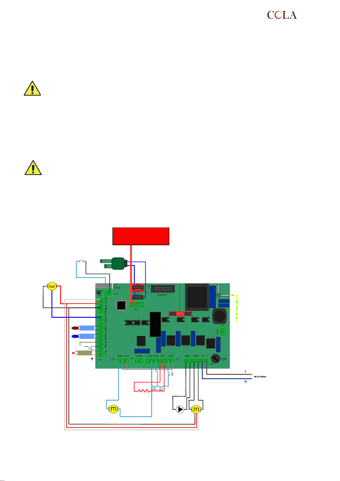
VIS SANS FIN
ALT= Thermostat de sécurité chambre de combustion
ALD= Dépressiomètre
ALP= Thermostat de sécu
Encodeur vérificateur fumées
NTC
2.5 Contrôle de la position du brasier et des turbulateurs
Avant d'allumer le poêle, contrôler que le brasier soit correctement encastré sur son support. Contrôler d'autre part
que le dispositif de secouage des turbulateurs se trouve au repos, c'est-à-dire en position basse. Un positionnement
incorrect du brasier et/ou des turbulateurs entraîne des anomalies de fonctionnement du poêle et un noircissement
excessif de la vitre.
Lors de chaque allumage de l'appareil, contrôler la position correcte du brasier et du dispositif de
secouage des turbulateurs.
2.6 Branchement électrique
Brancher le câble d'alimentation électrique d'une part à la prise arrière du poêle et, d'autre part, à une prise
électrique murale.
La tension de l'installation doit correspondre à celle indiquée sur la plaque d'identification du poêle et dans le
paragraphe des données techniques de ce manuel.
Pendant la période d'inutilisation du poêle, il est préférable de débrancher son câble d’alimentation.
- S'assurer que l'installation électrique est réalisé avec une connexion de mise à la terre du poêle et un
l'interrupteur différentiel conformément aux textes réglementaires et règles de l'art en vigueur.
- Le câble d'alimentation ne doit jamais entrer en contact avec le conduit d'évacuation des fumées du
poêle.
2.7 Schéma électrique
2.7.1 Schéma électrique base
FLUXOSTAT/THERMOSTAT
BALLON SANITAIRE
TRANSDUCTEUR
DE PRESSION
Encodeur vérificateur fumées
Sonde
Sonde
ambiante
additionnel
Sonde de
température
„fumées“
DÉBITMÈTRE
Consoles et accessoires
additionnels ondes
acheminées
BOUGIE
CARTE ÉLECTRONIQUE L23
POMPE
VENTILATEUR
D’EXTRACTION DES
FUMÉES
TERRE
rité réservoir à granulés
TERMO-POWER
89
Page 90
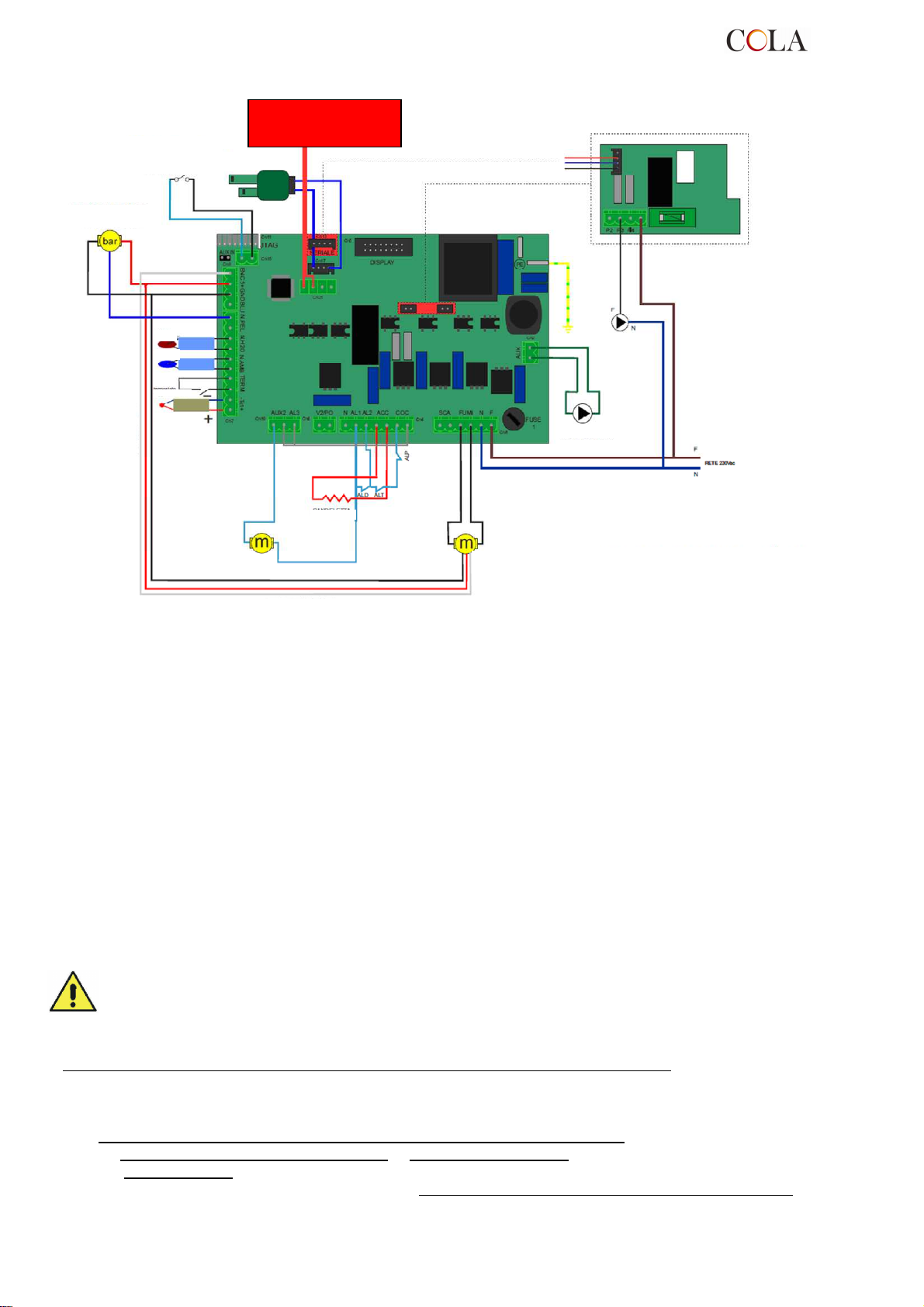
VIS SANS FIN
ALT= Thermostat de sécurité chambre de combustion
ALD= Dépressiomètre
ALP= Thermostat de sécurité réservoir à granulés
Encodeur vérificateur fumées
POMPE
2.7.2 Schéma électrique avec pompe de chauffage et sanitarie
FLUXOSTAT/THERMOSTAT
TRANSDUCTEUR
DE PRESSION
BALLON SANITAIRE
Sonde
NTC
Sonde
ambiante
additionnel
Encodeur vérificateur fumées
Sonde de
température
„fumées“
Consoles et accessoires
DÉBITMÈTRE
additionnels ondes
acheminées
BOUGIE
CARTE ÉLECTRONIQUE L23
TERRE
VENTILATEUR
D’EXTRACTION DES
FUMÉES
CARTE ÉLECTRONIQUE 1055
SANITARIE
POMPE
2.8 Schéma électrique pour installation à zones
Avant d'installer le poêle dans l'habitation, vérifier la typologie de l’installation de chauffage ; si elle compte
plusieurs zones, il faudra prévoir une unité électronique pour circuits avec gestion multizone disponible en option.
Ceci pour éviter de surchauffer la chambre de combustion au cas où les vannes de zone se fermeraient
simultanément, entraînant par la même occasion l'arrêt du débit d'eau chaude.
2.9 Raccordements hydrauliques
La puissance thermique du poêle doit être déterminée au préalable par un calcul des besoins thermiques de l'édifice
selon la réglementation en vigueur. L'installation doit être réalisée avec tous les composants nécessaires au
fonctionnement correct du poêle ; en fait, selon les règles de l'art, entre le poêle et le circuit de chauffage doivent
être montés les vannes d'arrêt et les clapets anti-retour qui permettent d'isoler le poêle du circuit lors des opérations
d'entretien et/ou des contrôles.Le remplissage d'eau de la chambre de combustion doit s'effectuer lentement pour
permettre une purge d'air correcte et complète.
Le circuit hydraulique de chauffage du poêle à granulés comprend notamment un circulateur, soupape de sûreté,
purgeur, sonde de température et transducteur de pression.
Dans le cas d'installation de chauffage multizone, il faudra impérativement prévoir une unité électronique avec
gestion multizone (disponible en option).
Pendant le transport, il est possible que les joints du système hydraulique se relâchent ou cèdent, en
provoquant des fuites d'eau pendant le fonctionnement normal du poêle ; il est donc conseillé de
contrôler le serrage des colliers des circulateurs et de la chambre de combustion pendant le remplissage
d'eau et après les premières heures de service, ainsi que de purger l'air résiduel dans le circuit.
Pour le raccordement du poêle au circuit sanitaire, faire appel à un technicien compétent, afin d'optimiser les
raccordements hydrauliques et les performances de l'installation sans compromettre l'efficacité de fonctionnement
du poêle.
Pour le raccordement du circuit sanitaire, il est nécessaire de prévoir un des accessoires optionnels suivants :
- une pompe sanitaire sur le collecteur de départ avec ses tubes de raccordement à placer à l'intérieur du poêle
- ou une pompe sanitaire, échangeur à plaques
- ou une vanne à 3 voies monostable à installer à l'extérieur du poêle.
La demande de ces accessoires vient s'ajouter à la carte (platine) électronique supplémentaire mod. ‘I055’ pour la
gestion des commandes avec l'éventuelle mise à jour du logiciel à implanter sur la carte de contrôle.
et tubes de raccordement à placer à l'intérieur du poêle
TERMO-POWER
90
Page 91
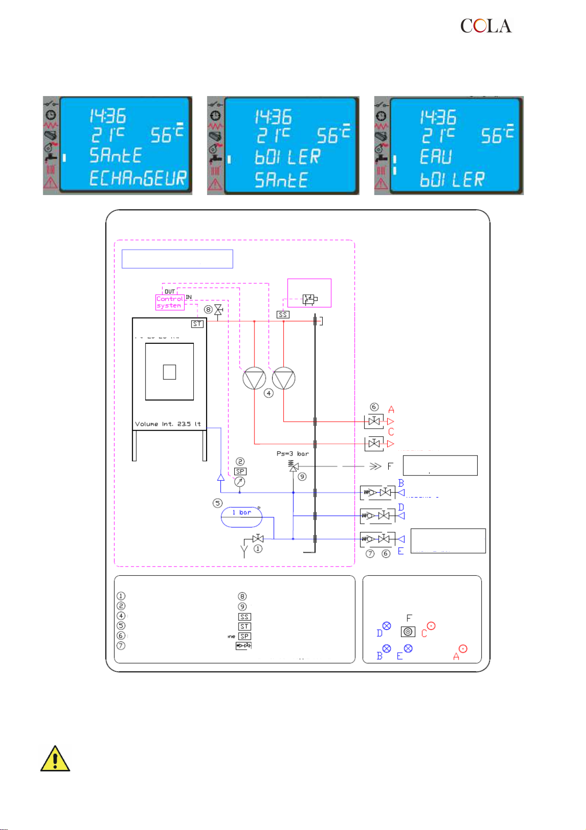
Le raccordement du circuit sanitaire terminé, accéder au menu technique du contrôle et sélectionner le type de
circuit ; chaque fonction sanitaire spécifique présélectionnée : ÉCHANGEUR SANITAIRE, BALLON ou BALLON
SANITAIRE apparaît sur l'écran au moment de la commutation chauffage-sanitaire, accompagnée d'un des
messages ci-dessous, et reste affichée jusqu'à la fin du besoin d'ECS signalé par le thermostat ou le débitmètre :
Schéma hydraulique du poêle chaudière à granulés réf. COLA 20-25kW_07-211
Poêle chaudière à granulés
Thermostat
Chambre de combustion
granulés – 2010
Pt=10-14 kW
LÉGENDE
Robinet de vidange
Capteur de pression/ Manomètre
Circulateur
Vase de pression à membrane
Robinet / vanne d'arrêt
Clapet anti-retour
Purgeur d’air chambre de combustion /Circuit
Soupape de sûreté P 3 bars max.
Capteur de sécurité
Sonde de température de l‘eau
Capteur de pression du circuit
Vannes à monter dans l’installation
pendant le montage – non fournies
avec l‘appareil
DÉPART
chauffage mâle 1“
DÉPART
chauffage mâle 3/4“
ÉVACUATION EAU EN
SURPRESSION F1
RETOUR
chauffage mâle 1“
RETOUR
RÜCKLAUF Heizung,
chauffage mâle 3/4“
Vaterteil ¾“
Alimentation réseau eau
de ville F1/2
Pmax 2 bar
Disposition des RACCORDEMENTS
HYDRAULIQUES à l'arrière du poêle
2.10 Première intervention
Il est toujours conseillé d'installer des équipements anti-incendie appropriés.
En cas d'incendie :
- Débrancher immédiatement le câble d'alimentation du poêle ;
- Éteindre le feu avec des extincteurs conformes à la réglementation en vigueur ;
- Appeler immédiatement les sapeurs-pompiers ;
- Ne pas utiliser de jets d'eau pour éteindre le feu.
TERMO-POWER
91
Page 92
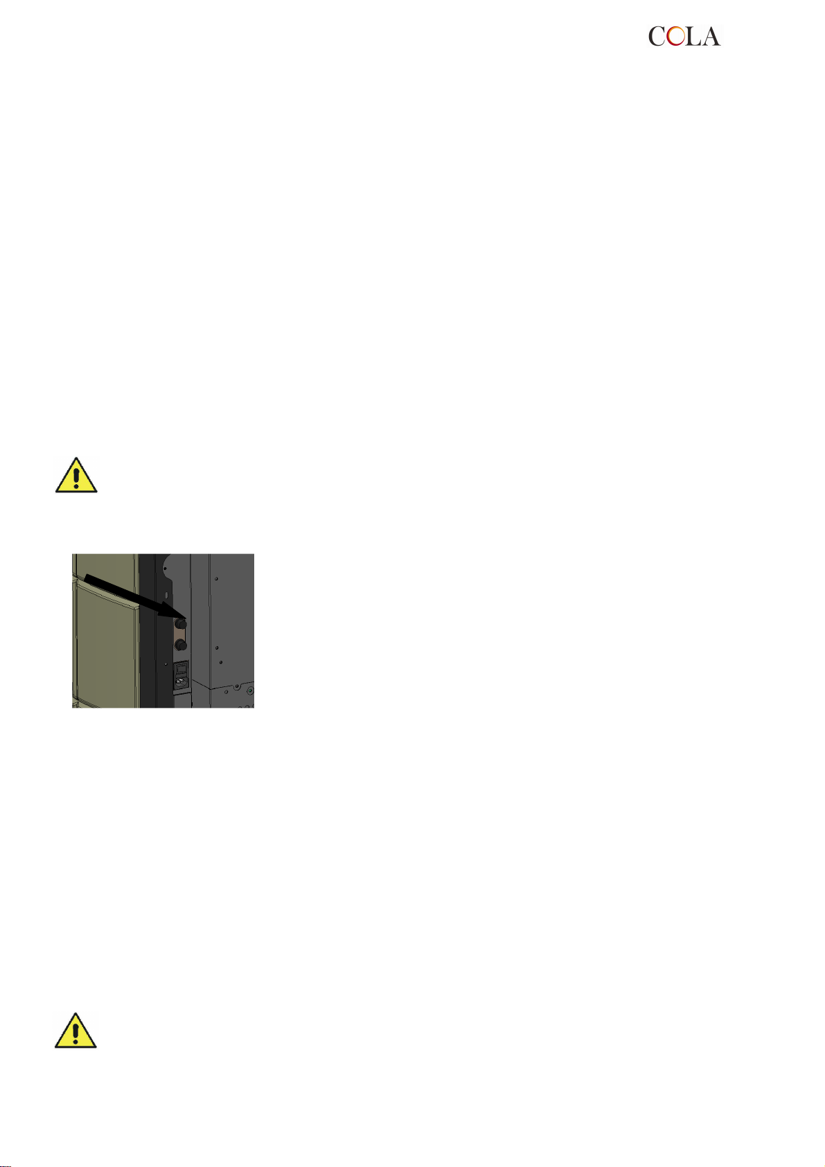
3 SÉCURITÉ
3.1 Distance de sécurité par rapport aux matériaux combustibles
Installer l’appareil à une distance minimale par rapport à tout matériau inflammable, afin d'éviter tout risque
d'incendie conformément aux indications présentes sur la fiche technique du manuel et sur la plaque de l'appareil.
Faire attention au type de sol : en cas de matériaux délicats et inflammables, il est recommandé d’utiliser des
plaques de sol en acier ou en verre trempé comme base d'appui (voir chapitre 2 Transport et Installation). En
présence d’objets considérés comme particulièrement délicats, tels que meubles, rideaux, divans, installer le poêle à
une distance plus éloignée de ceux-ci.
3.2 Sécurité pour l'évacuation des fumées
Normalement, la chambre de combustion fonctionne en dépression et garantit l'étanchéité contre toute fuite de gaz
dans l'environnement. En cas de valeur de dépression insuffisante ou de conduit de fumée obstrué, le vacuostat de
sécurité détecte le manque de dépression à l’intérieur de la chambre de combustion, ou le débitmètre décèle
l'absence de flux d'air comburant, et arrête le fonctionnement du moteur de rotation de la vis sans fin par
l'intermédiaire de l'unité. Le message ‘ AL8 MANQUE DÉPRESS ‘ ou ‘ AL9 TIRAGE INSUFF ‘ s'affichera alors sur le
tableau de commande.
3.3 Sécurité en cas de surpression dans la chambre de combustion
En cas de surpression inattendue des fumées de combustion à l’intérieur de la chambre et des conduits
d'évacuation, les fumées seront évacuées à travers des soupapes de sûreté installées au-dessus de l'échangeur de
chaleur. Durant le fonctionnement normal, ces soupapes restent fermées sous leur propre poids et sous l'effet de la
dépression de la chambre de combustion de sorte à garantir l'étanchéité contre l’évacuation éventuelle des fumées.
Contrôler régulièrement que le dispositif est fermé, qu'il est en bon état et qu'il fonctionne correctement.
3.4 Surchauffe - thermostats de sécurité
3.5 Sécurité contre le retour de flamme sur le canal d'alimentation des granulés
Les solutions pour empêcher le retour de flamme sont :
dépression dans la chambre de combustion, voir § 3.2.
►
La forme en siphon du canal d'alimentation des granulés.
►
La sécurité sur la température du réservoir, voir § 3.4.
►
3.6 Dispositif électrique de protection contre les surtensions
L’appareil est protégé contre les surtensions par un(des) fusible(s) de 2 A sur l'alimentation de l'interrupteur générale
du poêle situé à l'arrière de celui-ci.
3.7 Sécurité en cas de coupure de courant
Une coupure de courant momentanée ne limite pas le niveau de sécurité du poêle et la température du réservoir
n'atteint pas des valeurs trop élevées (< 85 °C), c ar la quantité de granulés dans le brasier est réduite.
Cette anomalie peut entraîner une légère fuite de fumées dans la pièce, mais ne comporte aucun risque.
Il est interdit d’intervenir sur les dispositifs de sécurité.
Sur la paroi basse du réservoir, et plus précisément sur le convoyeur
d'alimentation des granulés et dans la partie haute de la chambre de combustion,
sont situées deux sondes de température reliées à un thermostat de sécurité, qui
bloquent automatiquement l'alimentation des granulés en cas de surchauffe. Dans
ce cas, l’extracteur et/ou les ventilateurs continuent à fonctionner pour refroidir
plus rapidement l’appareil. L’anomalie est affichée sur le tableau de commande
par le message ‘ AL 7 SÉCURITÉ-THERMIQUE ’. En cas d'intervention, procéder
comme suit :
Laisser refroidir le poêle pendant au moins 45 minutes.
►
Rétablir le thermostat en appuyant le bouton proche de l'interrupteur derrière
►
le poêle (figure ci-contre).
Rallumer le poêle normalement.
►
Température de déclenchement du thermostat du réservoir de granulés : > 85 °C
Température de déclenchement du thermostat de la chambre de comb. : > 95 °C
TERMO-POWER
92
Page 93
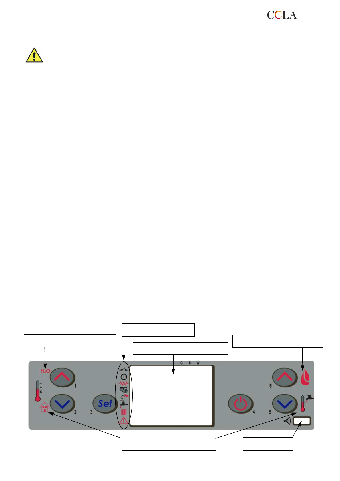
Écran LCD rétro
-
éclairé
3.8 Sécurité contre la surpression du circuit hydraulique
Toute surpression de l'eau à l'intérieur de la chambre, pour P>3 bars, est déchargée par la soupape de sûreté
installée sur le circuit hydraulique à l'intérieur du poêle.
Il est interdit d’intervenir sur les dispositifs de sécurité.
3.9 Dysfonctionnement du ventilateur d'extraction des fumées
Si pour une raison quelconque le ventilateur d'extraction des fumées s'arrête de fonctionner, l'électronique de
commande bloque instantanément l'alimentation des granulés et affiche le message ‘AL4 ASPIRAT-DÉFAILLANT’ .
4 UTILISATION DU POÊLE
4.1 Introduction
Le poêle à granulés offre l'avantage de combiner la chaleur de la flamme du bois et la commodité de la gestion
automatique de la température, avec la possibilité de programmer hebdomadairement l'allumage et d'extinction.
Il est possible d'effectuer le branchement à un thermostat et/ou chronothermostat externe pour mesurer la
température en un endroit différent de celui d’installation du poêle.
Pour une utilisation sûre et fiable du poêle, respecter les points suivants :
- il est possible de sentir de mauvaises odeurs lors de la première mise en service. Par conséquent, aérer
correctement la pièce pendant la première période de fonctionnement ;
- le remplissage du réservoir doit se faire exclusivement avec des granulés. Pendant cette opération éviter que le
sac entre en contact avec les surfaces chaudes du poêle ;
- ne pas introduire dans le réservoir d’autres types de combustible que les granulés conformes aux prescriptions ;
- ne pas utiliser le poêle comme incinérateur de déchets ;
- la porte du foyer doit toujours être fermée quand le poêle est allumé ;
- les joints de la porte du foyer doivent être contrôlés régulièrement pour éviter toute infiltration d’air ;
- le poêle doit toujours être propre pour garantir un bon fonctionnement et un rendement thermique efficace :
nettoyer le brasier à chaque chargement de granulés ;
- il est important au premier allumage de ne pas surchauffer le poêle, mais de le faire monter progressivement en
température en programmant des températures de fonctionnement basses (voir paragraphe programmation des
températures) ;
- pendant l’allumage le fonctionnement et l'extinction, le poêle peut émettre des cliquetis à cause de la dilatation
thermique.
4.2 Description du tableau de commande
Le tableau de commande comprend un écran LCD rétro-éclairé, une touche d'allumage/extinction (marche/arrêt)
‘P4’ , une touche de fonction SET/MENU ‘P3’, quatre touches de menu ‘P1’, ‘P2’, ‘P5’, ‘P6’ et 7 LED de signalisation
de l'état de fonctionnement du poêle.
Indications écran supérieur
Indicateurs d'état
Indications écran supérieur
TERMO-POWER
Indications écran inférieur
93
Récepteur IR
Page 94
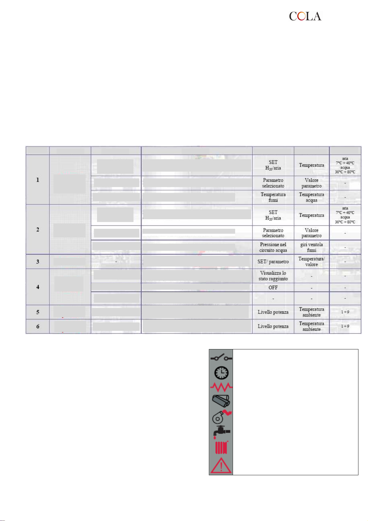
D
Afficheur supérieur
Afficheur inférieur
de la puissance
RÉGLAGE DE LA
RÉGLAGE DE LA
Éteint ou allume le poêle si pressé pendant 2 secondes selon
Permet de sortir du menu programmation à tout moment de la
Le tableau permet l'allumage et l'extinction (la marche/l'arrêt) du poêle, la régulation pendant le fonctionnement et le
paramétrage des programmes de gestion et d'entretien.
Sur l'écran sont affichées toutes les informations sur l'état de fonctionnement du poêle.
Pour accéder au menu :
- appuyer sur la touche CONSIGNE (SET) ‘P3’ ;
- appuyer plusieurs fois sur les touches ‘P5’,‘P6’ pour dérouler les menus ;
- appuyer sur une des touches d'augmentation/diminution ‘P1’, ‘P2’, pour ajuster le paramètre désiré ;
- appuyer sur la touche CONSIGNE (SET) ‘P3’ pour confirmer la valeur du paramètre.
Une fois rentré dans le menu, il est possible d'obtenir les différentes options de visualisation et d'effectuer les
paramétrages et/ou réglages disponibles suivant le niveau d'accès.
Le tableau ci-après indique les commandes et des messages correspondants affichés pendant la phase de
programmation ou présélection des paramètres de fonctionnement :
Bouton
escription Modalité Action
limites
Augmente la valeur de la température du thermostat d‘eau et
Augmentation
de la
TEMPÉRATURE
PROGRAMMATION
de celle du themostat d‘ambiance
Augmente le paramètre sélectionné
température
Affiche les températures
Augmente la valeur de la température du thermostat d‘eau et
de celle du themostat d‘ambiance
Augmente le paramètre sélectionné
Affiche les températures
Accède au RÉGLAGE de la température et au menu
utilisateur et technicien par pressions successives
que celui-ci soit respectivement éteint ou allumé
Débloque le poêle et le remet dans son état éteint
modification. Les modifications sont mémorisées
Diminue la puissance ou la valeur de la température
d'intervention du thermostat de sécurité eau du ballon sanitaire
Augmente la puissance ou la valeur de la température
d'intervention du thermostat de sécurité eau du ballon sanitaire
Diminution de
la température
Réglage/menu
ON/OFF
déblocage
Diminution de
la puissance
Augmentation
FONCTIONNEMENT
TEMPÉRATURE
PROGRAMMATION
FONCTIONNEMENT
FONCTIONNEMENT
BLOCAGE
PROGRAMMATION
FONCTIONNEMENT
FONCTIONNEMENT
La figure ci-contre fournit l'explication des indicateurs d'état sur
la partie gauche de l'écran.
L'activation, à l'écran, d'un des segments signale la mise en
service du dispositif correspondant, suivant la liste ci-contre.
Contact externe
Chrono
Résistance électrique
Vis sans fin
Extracteur de fumées
Activation du circuit SANITAIRE
Activation du circuit CHAUFFAGE
ALARME
TERMO-POWER
94
Page 95
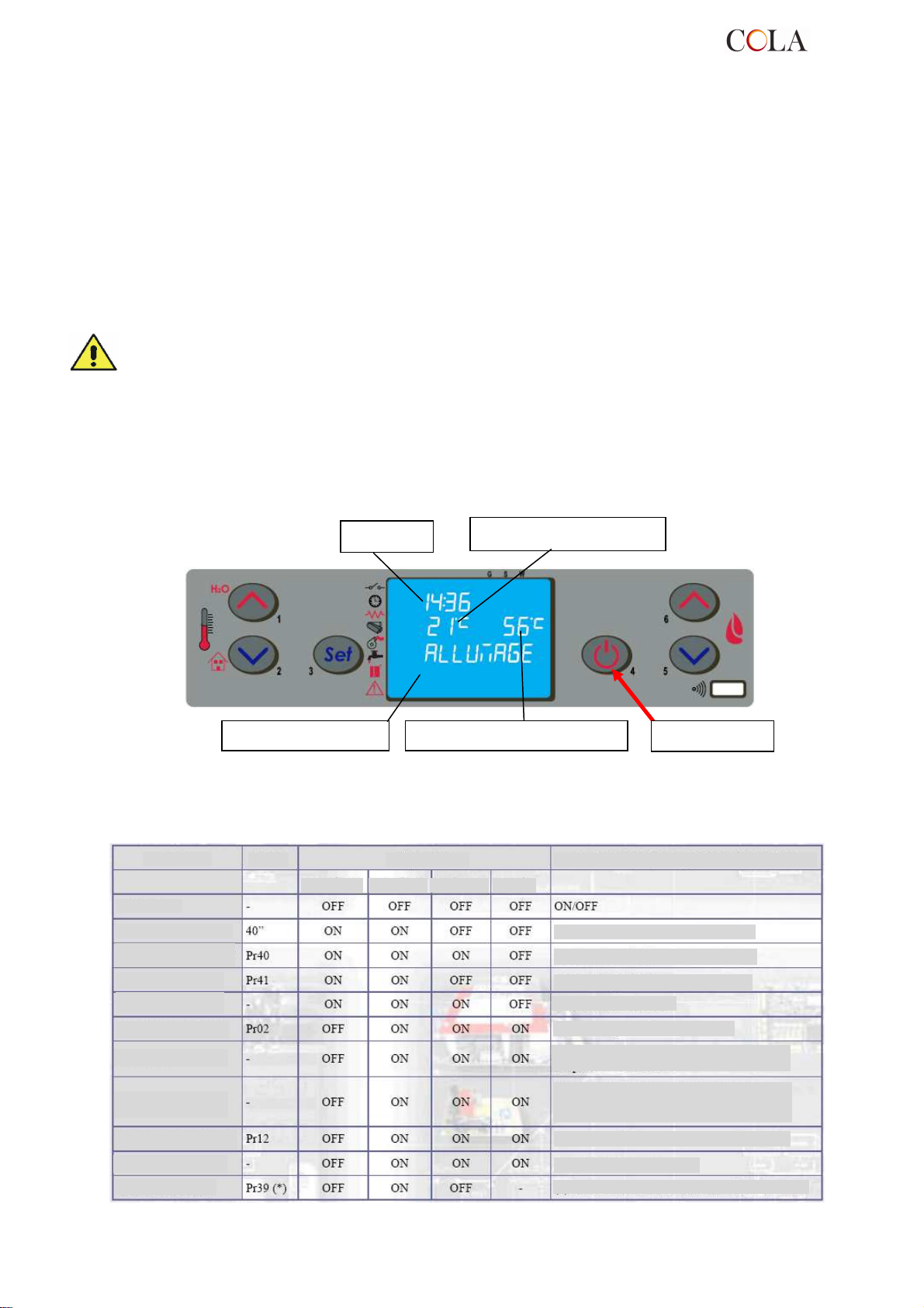
Fenêtre d
e dialogue
Température de l'eau
Bouton ‘P4’
RECHARGEMENT DES
GRANULÉS
4.3 Allumage
4.3.1 Contrôle avant l'allumage
Avant d'allumer le poêle, il faut :
- s'assurer d'avoir bien lu et compris les indications contenues dans le manuel ;
- s'assurer que le réservoir à granulés est rempli ;
- s'assurer que le chambre de combustion est propre ;
- s'assurer que le brasier est totalement libre, propre (sans dépôts) et correctement en place ;
- vérifier la fermeture hermétique de la porte de foyer et du cendrier ;
- vérifier le branchement du câble électrique et la commutation ON/1 de l'interrupteur monté à l'arrière du poêle.
- vérifier l'ouverture des vannes d'arrêt départ et retour, ainsi que la pression du circuit hydraulique.
- À la première mise en service, enlever du foyer et de la vitre de foyer toutes les choses qui pourraient
brûler (instructions/étiquette).
- Les allumages éventuels après de longues périodes d'inactivité du poêle ne doivent s'effectuer
qu'après avoir enlevé les résidus de granulés restés dans le fond du réservoir, car ils ne
s'enflammeraient plus (trop humide), et un nettoyage complet de la chambre de combustion.
4.3.2 Mise en marche
Pour allumer le poêle, appuyer sur le bouton ‘P4’ pendant 3 secondes : sur l'écran apparaîtra l'indication ‘START’.
Cette phase est automatique et est complètement gérée par l'électronique de commande. Il n'est pas possible ici
d'intervenir sur les paramètres.
Horloge
Température ambiante
Le poêle exécute successivement les phases de mise en route selon les paramétrages définis qui en gèrent les
niveaux et les temps d'exécution, jusqu'à l'obtention du régime normal à moins que ne surviennent des anomalies
ou ne se déclenchent des alarmes, selon le tableau suivant :
État
ÉTEINT
START – PRÉCHAUF.
ATTENTE FLAMME
CHARGEMENT DES
GRANULÉS
FEU PRÉSENT
FONCTIONNEMENT
FONCTIONNEMENT
MODULE
NETTOYAGE DU BRASIER
FONCTIONNEMENT
NETTOYAGE FINAL
Durée
Dispositifs Conditions pour passer à l’état suivant
Allumeur Asp. fumées Vis sans fin Échang.
Après un laps de temps de 40“
Après un laps de temps de 40“
Après un laps de temps de 41“
Température des fumées
Après un laps de temps de Pr02 Sek.
Température ambiante < CONSIGNE température
Température des fumées
Température ambiante < CONSIGNE température
Température de l’eau < CONSIGNE eau
Température des fumées
Avec une fréquence Pr03
ON/OFF pour éteindre
(*) Pr39 S’écoule à partir du moment où T. fumées. < Pr13
TERMO-POWER
95
Page 96
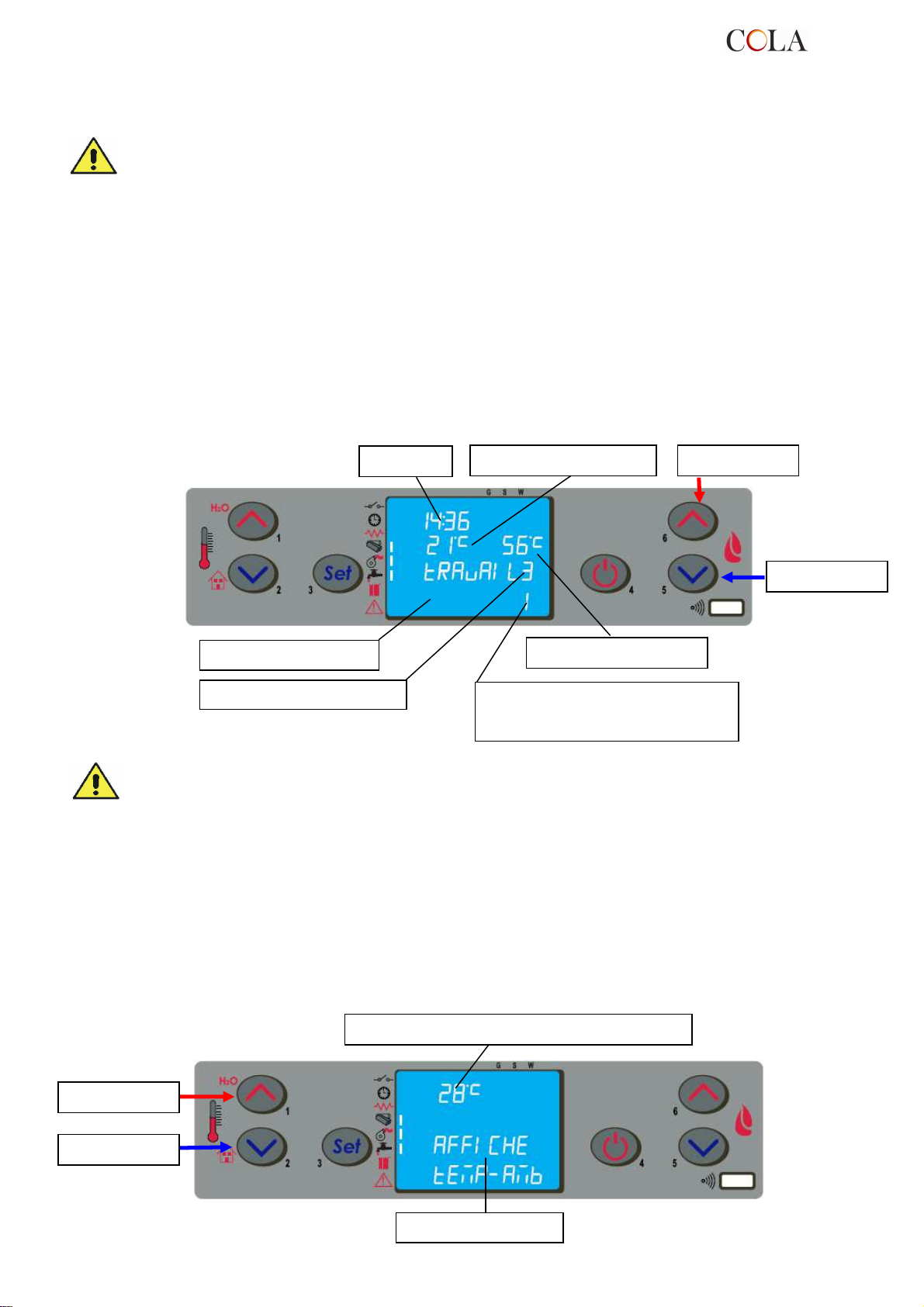
Fenêtre de dialogue
Bouton ‘P1’
Fenêtre de dialogue
Puissance préréglée à
3
Passé un certain temps, si la température des fumées atteint la valeur min. admissible, le poêle se mettra en
position d'alarme.
- Il est interdit d'utiliser des liquides inflammables pour l'allumage du poêle.
- En cas d'allumages manqués répétés, faire appel au SAV.
En alternative, il est possible d’allumer le poêle en appuyant simultanément sur les touches P4 et P5 pendant 3
secondes. Sur l’écran apparait “ATTENTE DEMANDE”. Dans ce mode, le poêle est en attente de fonctionnement et
se mettra en phase de démarrage s’il reconnait une demande de chaleur pour le chauffage ou pour l’eau chaude
sanitaire (si disponible).
4.4 Fonctionnement
Après la phase de démarrage réussie, le poêle passe en mode ‘FONCTIONNEMENT‘ qui représente le régime
normal.
L'utilisateur peut alors régler la puissance de chauffe par les boutons ‘P6’ et ‘P5’, de la valeur max. 5 à la valeur
min. 1.
Horloge
Température ambiante
Bouton ‘P6’
Bouton ‘P5’
Température de l'eau
Puissance réelle en fonctionnement
équivalent à 1 - clignote
- Il est recommandé de contrôler le niveau des granulés dans la trémie, afin d'éviter que la flamme ne
s'éteigne pour cause de manque de granulés.
- S'assurer que l'appareil est éteint pour effectuer le chargement des granulés.
- Le couvercle de la trémie (réservoir à granulés) doit toujours rester fermé. Il ne dot être ouvert que pour
effectuer le chargement des granulés.
- Les sacs de granulés doivent être stockés à une distance d'au moins 1,5 m du poêle.
4.4.1 Modification du préréglage de la température ambiante
Pour modifier la température ambiante, il suffit de sélectionner l'option AFFICHE T°AMBIANTE en appuya nt sur le
bouton P2 .
Appuyer ensuite sur les boutons ‘P1’ et ‘P2’ : sur l'écran apparaîtra l'état courant de la CONSIGNE (SET) de
température.
Valeur préréglée de la température ambiante
Bouton ‘P2’
TERMO-POWER
96
Page 97
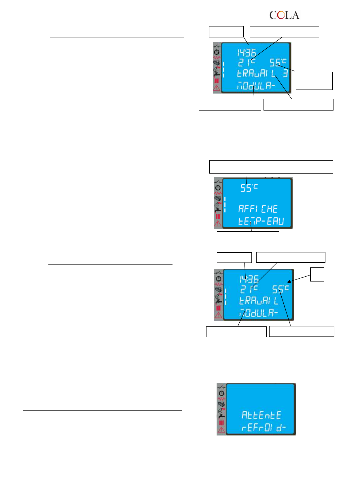
Horloge
Température ambiante
Fenêtre de dialogue
Température
l’eau
Horloge
Température ambiante
Température de l'e
au
Fenêtre de dialogue
Quand la température ambiante a atteint la valeur préréglée, ou
bien la température des fumées a atteint la valeur max. préréglée,
la puissance est automatiquement amenée à la valeur minimale,
en condition de MODULATION.
Si le mode VEILLE (STAND-BY) est activé, le poêle s'éteint à
retardement après avoir atteint la CONSIGNE (SET) de
température. Le redémarrage ne se produira que lorsque la
température ambiante sera inférieure à une certaine valeur
prédéfinie par rapport à la température ambiante.
Lorsque la température des fumées arrive à la température maximum réglée sur le tableau de commande, le
message “MODULA F” apparait sur l’écran et le poêle active la procédure de modulation de flamme sans
l’intervention de l’utilisateur. Si la température des fumées dépasse le 280°C, l’alarme « ALLARM HOT FUMI »
apparaît alors et le poêle active la procédure d’arrêt.
4.4.2 Modification du préréglage de la température de l'eau
Puissance préréglée
Valeur préréglée de la température de l'eau
Pour modifier la température de l'eau, il suffit de sélectionner
l'option AFFICHE TEMP EAU en appuyant sur le bouton P1.
Appuyer ensuite sur les boutons ‘P1’ et ‘P2’ : sur l'écran apparaîtra
l'état courant de la CONSIGNE (SET) de température.
Quand la température de l'eau a atteint la valeur préréglée,
même simultanément à la condition décrite §.4.4.1, la puissance
est automatiquement amenée à la valeur minimale, en condition
de MODULATION.
Dans la version Idro, lorsque la condition imposée par la
température de consigne n’est pas satisfaite, l’écran laisse
apparaître le segment/led [A].
4.4.3 Remise en marche à partir du mode VEILLE (STAND-BY)
Après l'extinction, le poêle se met en condition refroidissement en
amenant la vitesse d'extraction des fumées à la valeur préréglée
pour le nettoyage du creuset. Le redémarrage survient dès que la
température ambiante a atteint la valeur de CONSIGNE (SET).
Fenêtre de dialogue
A
TERMO-POWER
97
Page 98
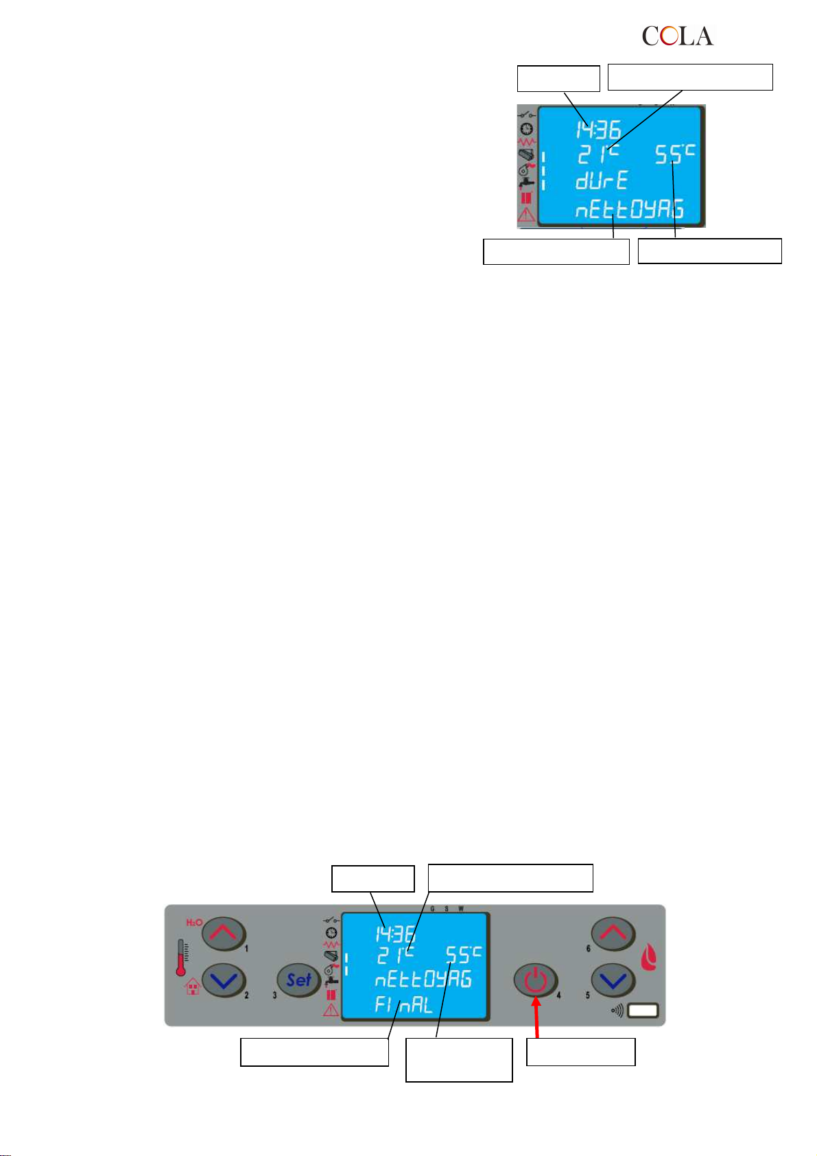
Température ambiante
Horloge
Fenêtre de dialogue
Puissance préréglée
Horloge
de l'eau
4.4.4 Nettoyage du brasier
Pendant le fonctionnement normal, à intervalles prédéfinis, la
modalité ‘DURE NETTOYAG’ pour une durée prédéfinie est
activée.
4.4.5 Eau chaude sanitaire avec échangeur rapide.
Lorsqu’il y a une demande d’eau chaude sanitaire, l’écran du tableau de commande affiche “SCAM SANIT” et le LED
indiquant un robinet s’allume. La production d’eau chaude sanitaire est possible si le poêle est allumé et lorsque la
température du corps de chauffe est suffisante. Dans les autres cas, la production d’eau chaude sanitaire n’est pas
disponible.
4.4.6 Eau chaude sanitaire avec un préparateur d’eau chaude.
Pour ce type d’installation, il est nécessaire d’utiliser un thermostat ballon extérieur qui mesure la température de
l’eau dans le ballon. Lorsque la température mesurée descend en-dessous de la température de consigne du
thermostat, la fonction sanitaire s’active, l’écran du tableau de commande du poêle affiche « BOILER SANIT » et le
LED indiquant un robinet s’allume jusqu’à ce que la demande soit satisfaite.
Si le poêle est en phase “ATTENTE DEMANDE”, il s’allume automatiquement et se met en mode “TRAVAIL”. Quand
la température de l’eau du corps de chauffe est suffisante, la production d’eau chaude sanitaire est activée.
Lorsque la température de consigne du thermostat ballon est atteinte, le poêle utilise l’excédant de production de
chaleur pour l’installation ce chauffage pour une durée de 2 minutes, ensuite s’il n’y a pas de nouvelles demandes, le
poêle se met en mode “ATTENTE DEMANDE” ou en MODULATION, selon les réglages choisis (voir cf. 4.6.5).
Si le poêle est en “ARRET”, il ne s’allume pas et ne fait pas de production de chaleur.
4.4.7 Installation avec un ballon d’accumulation
Ce type d’installation requiert l’utilisation d’un thermostat ballon extérieur qui mesure la température de l’eau à
l’intérieur du ballon. Quand la température descend en-dessous de la température de consigne du thermostat, l’écran
du tableau de commande du poêle affiche “ACQUA PUFFER” ou “ACQUA BOILER” et 2 LED indiquant
respectivement un robinet et un radiateur s’allument puisque cette installation peut satisfaire une demande chauffage
et sanitaire.
Si le poêle est en phase “ATTENTE DEMANDE”, il s’allume automatiquement et se met en mode “TRAVAIL”. Une
fois la température de travail atteinte dans le corps de chauffe, la production de chaleur vers le ballon d’accumulation
est activée.
Quand la température de consigne du ballon est atteinte, le poêle se met en mode “ATTENTE DEMANDE” (si le
paramètre STAND-BY est réglé sur ON, voir paragraphe. 4.6.5).
Si le poêle est en “ARRET”, il ne s’allume pas et ne fait pas de production de chaleur.
4.5 Extinction
Pour arrêter le fonctionnement du poêle, il suffit d'appuyer sur le bouton ‘P4’ pendant 2 secondes environ.
La vis sans fin est immédiatement stoppée et l'extracteur des fumées est amené à fonctionner à une allure élevée.
Sur l'écran apparaît alors l'indication ‘NETTOYAG FINAL’.
Température ambiante
TERMO-POWER
Fenêtre de dialogue
Température
98
Bouton ‘P4’
Page 99
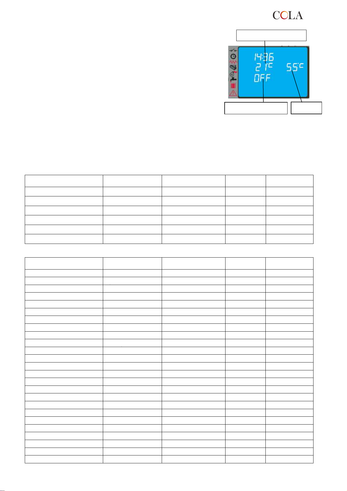
01 – activation du
03 –
program
Température ambiante
Sur l'écran, dans la fenêtre de dialogue, apparaîtra l'indication
‘OFF’ au terme de l'opération.
Pendant la phase d'extinction, il n'est pas possible de remettre en
marche le poêle jusqu'à ce que la température des fumées n'est
pas descendue en dessous d'une valeur prédéterminée pour une
durée prédéfinie. Dans la fenêtre de dialogue apparaît alors
l'indication ‘ATTENTE REFROID’.
Fenêtre de dialogue
T° eau
4.6 Menu
Appuyer sur la touche ‘P3’ (SET) pour entrer dans le menu qui propose différentes options et différents niveaux
permettant d'accéder aux paramétrages de l'électronique de commande.
Le tableau ci-après résume la structure du menu avec les seules options disponibles pour l'utilisateur.
Niveau 1 Niveau 2
Niveau 3
Niveau 4
Valeur
02 – réglage de l'horloge
02 - heures Heures
03 - minutes Minutes
04 - jour Jour
05 - mois Mois
06 - année Année
Niveau 1 Niveau 2
03 – réglage du chrono
01 – chrono jour on / off
02 – start 1 jour heure
03 – stop 1 jour heure
04 – start 2 jour heure
05 – stop 2 jour heure
01 – chrono semaine on / off
02 – start 1 jour heure
03 – stop 1 jour heure
04 – lundi prog 1 on / off
05 – mardi prog 1 on / off
06 – mercredi prog 1 on / off
07 – jeudi prog 1 on / off
08 – vendredi prog 1 on / off
09 – samedi prog 1 on / off
10 – dimanche prog 1 on / off
11 – start prog 2 heure
12 – stop prog 2 heure
13 – lundi prog 2 on / off
14 – mardi prog 2 on / off
15 – mercredi prog 2 on / off
01 - jour Jour
02 – program jour
Niveau 3
01 – activation du
Niveau 4
on / off
Valeur
TERMO-POWER
99
Page 100
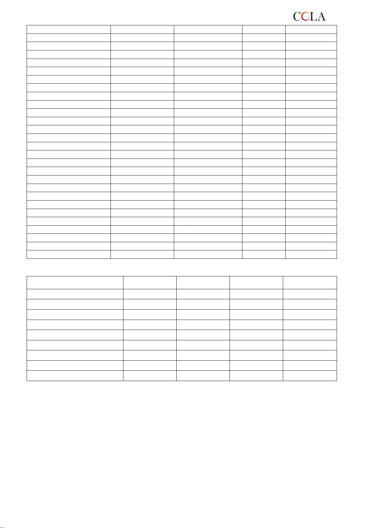
04 – program
16 – jeudi prog 2 on / off
17 – vendredi prog 2 on / off
18 – samedi prog 2 on / off
19 – dimanche prog 2 on / off
20 – start prog 3 heure
21 – stop prog 3 heure
22 – lundi prog 3 on / off
23 – mardi prog 3 on / off
24 – mercredi prog 3 on / off
25 – jeudi prog 3 on / off
26 – vendredi prog 3 on / off
27 – samedi prog 3 on / off
28 – dimanche prog 3 on / off
29 – start prog 4 heure
30 – stop prog 4 heure
31 – lundi prog 4 on / off
32 – mardi prog 4 on / off
33 – mercredi prog 4 on / off
34 – jeudi prog 4 on / off
35 – vendredi prog 4 on / off
36 – samedi prog 4 on / off
37 – dimanche prog 4 on / off
02 – start 1
01 – chrono week-
03 – stop 1
04 – start 2
05 – stop 2
on / off
Niveau 1 Niveau 2
Niveau 3
Niveau 4
Valeur
04 – choix de la langue
01 - italien set
02 - français set
03 - anglais set
04 - allemand set
05 – mode veille (stand-by)
06 – alarme sonore (buzzer)
07 – chargement initial
08- État du poêle
on / off
on / off
set
-
4.6.1 Menu 01 – réglage des ventilateurs
L'option de menu 01, si validée, régule l'allure (la vitesse) des ventilateurs additionnels (non disponibles).
4.6.2 Menu 02 – réglage de l'horloge
Avant de faire fonctionner le poêle, il faut d'abord régler l'heure et la date courante, pour permettre d'effectuer la
programmation du chrono.
Le régulateur électronique est équipé d’une batterie lithium mod. CR2032 de 3 Volt qui permet à l’horloge interne,
une autonomie supérieure à 4 ou 5 ans ; si lorsque le poêle est arrêté, l’horloge ne maintient pas l’horaire ou au
rallumage apparaît une série de zéro, il sera nécessaire de procéder à son remplacement en appelant le centre
d’assistance agréé.
TERMO-POWER
100
 Loading...