

Page 1
Installation, use and maintenance
manual
Combined heating stove
model TERMO EMMANUELLE
Read the instructions carefully before installation and startup
48.41.35.011.EN 07/09
Page 2

1 T.Emmanuelle
1 - GENERAL INFORMATION
1.1 Introduction
1.2 Safety rules
1.3 Technical description
1.3.1 Ash and fire door
1.3.2 Primary air controls
1.3.3 Cast iron hotplate
1.3.4 Bypass damper
1.3.5 Oven
1.3.6 Baffle cleaning door
1.3.7 Electric oven and hob: instructions
1.3.8 Thermostat
1.3.9 Grate raising screw
1.4 Fuel
1.5 Accessories supplied
1.6 Reference standards
1.7 Dataplate
1.8 Ordering replacement parts
1.9 Stove decommissioning
2 – TRANSPORT AND INSTALLATION
2.1 Packing, handling, shipment and transport
2.2 Installation instructions
2.3 Connection to the flue
2.4 Room ventilation
2.5 Electrical connection
2.6 Gas connection
2.7 Plumbing connection
2.8 Advice on flues and connections
3 – STOVE USE
3.1 Introduction
3.2 Startup
3.3 Lighting and controlling the fire
3.4 Adjusting the combustion air
3.5 Normal operation
3.6 Operation with partial feed
3.7 Using the hob and electric oven
3.8 Operation in off season
3.9 Wood-fired oven operation
3.10 Idle period
4 – ROUTINE STOVE CLEANING AND MAINTENANCE
4.1 Removing the ash
4.2 Cleaning the glass
4.3 Stove cladding maintenance
4.4 Cleaning the cast iron hotplate
4.5 Cleaning the wood-fired oven
4.6 Cleaning the hob
4.7 Cleaning the flue and baffle
5 – TROUBLESHOOTING
5.1 The stove does not work
5.2 Difficult lighting
5.3 Smoke leaks
5.4 The glass gets dirty quickly
5.5 Condensate in the heating chamber
5.6 The wood-fired oven does not heat
5.7 Radiators or heating system inefficient
5.8 The electric fan oven does not work
5.9 The gas hob does not work
6– ENCLOSURES
6.1 Warranty certificate
6.2 "CE" marking information
Page 3

2 T.Emmanuelle
1 - GENERAL INFORMATION
1.1 Introduction
Dear Customer
First of all we wish to thank you for the trust placed in us by purchasing one of our products. Please read and
carefully follow the advice given in this installation, use and maintenance manual in order make best use of the
product.
- Installation, testing and cleaning must be carried out according to that described in this manual, and
in compliance with local regulations, including the national and European reference standards;
otherwise the product warranty will be invalidated.
-
Have the flue inspected by a specialised technician;
For operation faults, doubts or problems please contact your nearest service centre.
Cola s.r.l. declines any liability for problems, breakage or accidents caused by failure to follow or apply the
instructions contained in this manual.
1.2 Safety rules
- Read and follow the instructions given in the installation, use and maintenance manual.
-
With the HEATING model , the stove must never be used without being connected
to the heating system and without water in the heating chamber.
- Connect the stove to an approved flue not shared with other appliances.
- Make sure the stove is cold before carrying out any cleaning or maintenance.
- Do not use flammable liquids or substances such as alcohol or hydrocarbons to light the stove.
- The stove is suitable for intermittent combustion and must only be used with fuels having the
characteristics described in this manual.
- The room where the stove is installed must have openings or air inlets communicating with the outside of the
house and able to ensure a sufficient air change.
- Never close the combustion air inlet and fume outlet openings.
- Do not handle easily flammable or explosive substances in the vicinity of the stove when it is operating.
- During operation, the intense heat generated by combustion of the wood makes the outside surfaces of the
stove very hot, and in particular the fire door, handle, fume exhaust pipe and cover; therefore
avoid contact with such parts without suitable protection.
- Keep objects which are not heat resistant at a suitable distance.
- Clean the ash pan regularly.
- Hot ashes must not be put in waste bins or left unattended outdoors.
- Warn children and guests about the hazards described above.
- In case of operation anomalies, relight the stove only after eliminating the cause of the problem.
- Very hot fats and oils tend to catch fire easily, therefore food rich in fatty substances
- must be prepared with maximum attention.
- If a foul air/steam extractor hood is operated in the same area or near the stove, burnt gases may escape
from the fire door during loading, if the room is not adequately aired from the outside.
- The oven/food-warmer must only be used for its intended purpose, i.e. for heating and/or cooking food; any
other use is deemed improper and hazardous.
For the electrical connection, respect the following additional rules:
- Connect the stove to an approved 230 Volt - 50 Hz electrical socket.
- The power cable must be connected to a controlled socket.
- Make sure the electrical system and sockets are suitable for the max. absorption of the appliance, given on
the label and in this manual and the enclosures
Cola s.r.l. declines any liability for problems, breakage or accidents caused by failure to follow or apply
the instructions contained in this manual.
Page 4
3 T.Emmanuelle
1.3 Technical description
The EMMANUELLE heating stove is suitable for cooking and heating and is tested for use exclusively with
wood.
Structure:
in steel and cast iron
Radiant hotplate:
in cast iron
Fire door:
H x W 225x245 mm
Combustion chamber:
in sheet steel Fe 360 int. thick. 4 mm and ext. 3 mm.
Wood-fired oven:
In stainless steel H x W x D 255x320x520 mm
Flue pipe:
150 mm
Fume outlet:
Top (rear with modification)
Flue gas temperature:
283 °C
Required draught:
10 –14 Pa
Nominal power:
27 kW
Water heating power:
21.5 kW
Max. fuel consumption:
8.7 kg/h
Efficiency:
73 %
Exchanger capacity:
35 litres
Max. operating pressure:
2 bar
Weight:
355 kg
Min. distance rear - sides:
200 mm
External dimensions:
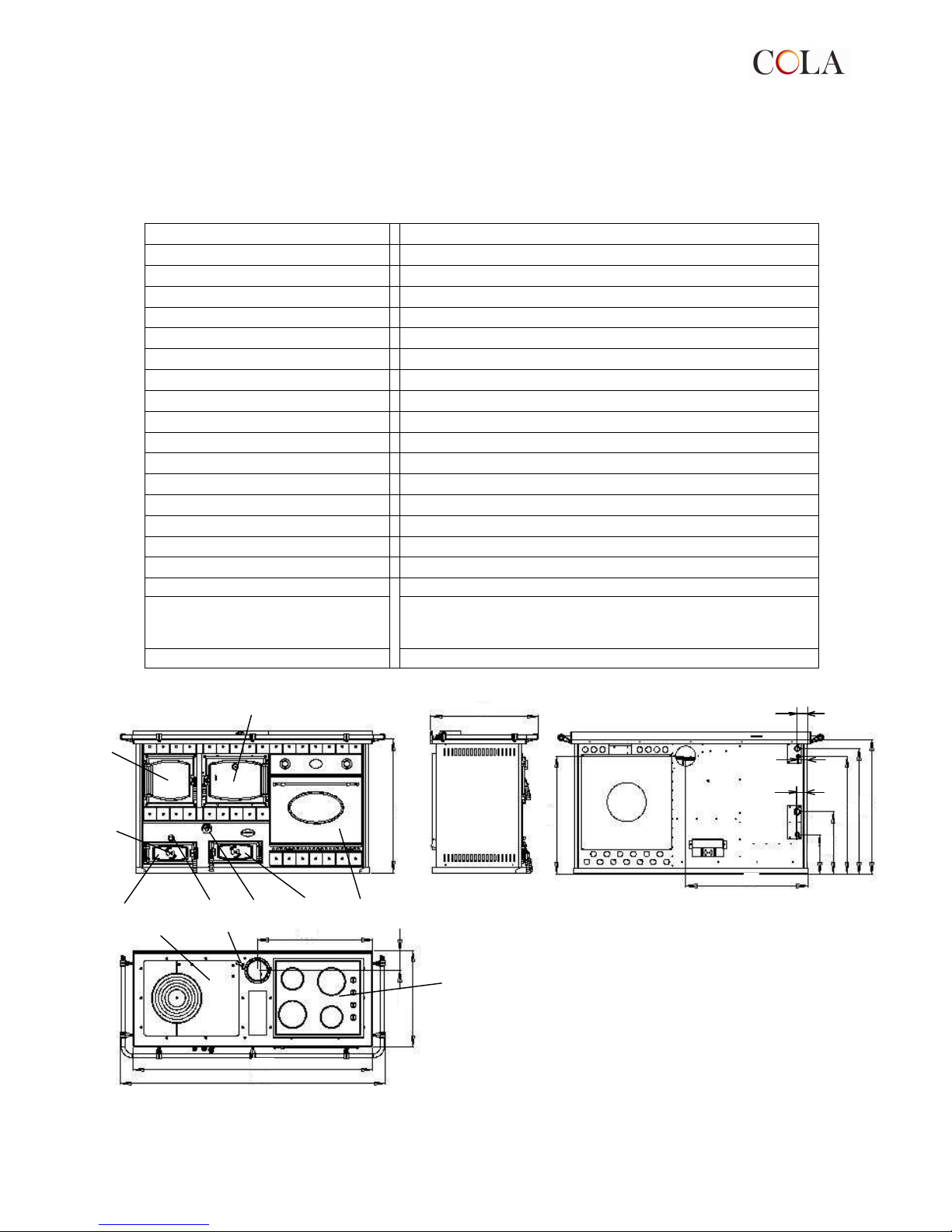
H x W x D= 860x1700x685 mm (fig.1)
ILVE electric oven
Fan-assisted in enamelled steel,
230 VAC, 50 Hz, max. power 2500W
internal volume: 53 litres
ILVE hob
230 VAC, 50 Hz, 0.6W
A
C
H
G
F E
D
B
L
I
M
860
784
755 752
398
685
737
1700
62
56
62
Fig.1 Ingombri termo cucina Emanuelle
Page 5

4 T.Emmanuelle
1.3.1 Fire door (C) and ash door (A)
The doors are opened by pulling the handles outwards. A protective glove is supplied for opening the stove fire
door (the handles become very hot). The ash zone has an adjustable combustion air inlet opening for use
during the lighting stage.
1.3.2 Secondary air controls (B)
By means of the revolving air control on the ash door the primary air can flow into the lower part of the stove
through the ash pan and grate. The air control must be turn to zero (closed) when adjusting combustion with
the thermostat (G)
1.3.3 Cast iron hotplate (I)
The cast iron hotplate has rings, which indicate the hottest zone. These rings can be removed with the poker.
The hotplate has an opening for inserting the water tank.
1.3.4 Bypass damper butterfly valve (L)
The bypass damper is located above the hotplate. By turning the knob to position Z, the flue gases are
conveyed directly to the outlet, evenly heating the hotplate.
By turning the knob to position A, the flue gases are forced to circulate around the oven, thus evenly raising the
temperature.
1.3.5 Wood-fired oven (D)
The oven temperature increases due to the hot combustion gases flowing around it. A sufficient draught and
clean fume ducts are essential for optimum efficiency. The oven is supplied with two racks. Its temperature can
be read on the thermometer located on the door glass. Adequate temperatures for cooking can be reached with
the door closed. When putting pans in the oven, take into account the possible rising of food and the minimum
space between pans and the sides of the oven (min. 20 mm).
1.3.6 Baffle cleaning door (F)
Used to clean the bottom baffle and to remove any deposits from under the oven.
During stove operation the door must be hermetically closed.
1.3.7 Hob (M) and electric oven (E): instructions
Before using the hob and the electric oven make sure to carefully read the enclosed Manufacturer's manual
which contains very important information regarding safe installation, use and maintenance. Keep the manuals
for future reference.
Remember that gas appliances must be installed in well-ventilated rooms in order to function properly.
Therefore, make sure to consult the section on installation in the Manufacturer's manual.
When using gas appliances, several simple safety rules must be observed:
1-do not place unstable or deformed pots that could tip over on the burners or electric hotplates;
2-place pots on the hob with the handles turned inwards so that they are not knocked;
3-when using small electrical appliances near the hob, make sure the power cable does not touch any hot parts
of the hob.
Electric oven safety is guaranteed only if the earth connection has been correctly carried out in conformity with
the current standards. Make sure these standards are respected; in case of doubt contact qualified personnel
for checking the electrical system.
The Manufacturer declines any liability for damage caused by an inefficient earthing system.
1
.3.8 Thermostat (G)
The thermostat controls the inlet of combustion air. It therefore adjusts the water temperature, from the inlet
temperature to a max. temperature of approx. 70°C. With the thermostat set to 0 and the secondary air control
on the ash door closed, the heating stove tends to shut down due to the lack of combustion air.
When the thermostat is set to position 5, the combustion air is controlled in such a way as to maintain the
heating chamber water at a temperature of approx. 70°C.
Page 6

5 T.Emmanuelle
1.3.9 Grate raising screw (H)
The grate raising device is operated by means of a nut located above the ash door on the front of the heating
stove.
When the heating stove is used for cooking on the hotplate and in the oven, it is advisable to raise the ash
grate by turning the nut using the wrench supplied
1.4 Permissible and non-permissible fuels
Permissible fuels are dry and resin-free natural-type logs of wood (beech, oak and birch), 20-25 cm long. The
wood should be seasoned for at least two years; the maximum recommended moisture content is 20%, in order
to ensure combustion without smoke and soot.
Do not use:
- coal dust;
- thinly cut pieces of wood (permissible only in the lighting stage);
- bark and chips;
- waste in general;
- treated paper and cardboard;
- wood treated with protective substances.
The burning of waste is prohibited according to European and national laws.
The burnt gases produced by the combustion of unsuitable materials can cause damage to the stove
and flues, and compromise your health.
The use of any fuel not complying with that specified above invalidates the warranty.
1.5 Accessories supplied
The supply includes:
- operating instructions;
- poker;
- glove for hot handles;
- wrench for lifting the grate.
1.6 Reference standards
UNI 10683/98: standard prescribing the installation requirements for heat generators or appliances also
intended for cooking food, such as stoves and heating stoves with natural draught on fume side and
forced draught with thermochemical power of 35kW< using natural wood
.
Standard EN 12815: European standard for solid fuel stoves, containing the design, fabrication, construction,
safety and performance requirements, instructions and markings, together with the relevant type-testing
methods.
Standards EN 60335-1 and EN 50165: standards regarding electrical equipment on non-electric appliances.
1.7 Dataplate
The dataplate is located on the back of the stove. It gives the following data:
- model;
- serial number;
- type of fuel;
- nominal heat output;
- consumption;
- min. flue draught;
- flue gas temperature;
- thermal efficiency;
- flue pipe size;
- stove external dimensions;
- min. safety distance;
- weight.
Page 7

6 T.Emmanuelle
1.8 Ordering replacement parts
For the end-user:
Contact the service centre and/or your dealer to request replacement parts.
For the dealer:
To request any replacement parts contact the Cola s.r.l. service centre and/or send a fax clearly specifying the
following data:
- stove model;
- serial number;
- date of purchase;
- list of replacement parts;
- details of faults encountered.
- Operations on parts must be carried out by authorised and/or qualified personnel.
- Only use original Cola replacement parts.
1.9 Stove decommissioning
For disposal, the stove must be sealed inside strong packing; contact your local authority for information on how
to proceed in accordance with current regulations.
2 – TRANSPORT AND INSTALLATION
2.1 Packing, handling, shipment and transport
The stove can be lifted using a lift truck, inserting the forks (of suitable length) in the special spaces in the
wooden packing.
Make sure the equipment used for lifting and transport can take the weight of the stove, specified on the
dataplate and in this manual.
Avoid taking the load in areas where it could be a danger if dropped.
Set the stove down on the floor carefully without jolting and position it in the required place. Make sure the floor
can support the weight of the stove, otherwise consult a specialised technician.
2.2 Installation instructions
Correct operation of a range or heating stove depends above all on its installation, which must be carried out by
a competent person in compliance with the current safety regulations.
An incorrectly installed stove can be the cause of serious accidents (flue, insulation materials, etc.,
catching fire).
The sides and back must be at least 20 cm from flammable materials. If the floor is made of flammable material
(wood, carpets, etc.) provide for a protection base in sheet metal (recommended min. thickness 2-3 mm).
2.3 Connection to the flue
The EMMANUELLE heating stove must be connected to the flue by means of the collar on the hotplate, using
flue pipes that are readily available on the market. Connection to the flue must be made using strong and stable
pipes (recommended min. thickness 2 mm). The flue pipe must possibly be straight, to avoid pressure losses,
and towards the flue. The individual parts of the flue pipe must be sealed.
To ensure regular operation, the flue draught with stove operating must be between 10 and 14 Pa.
For optimum stove efficiency, a draught control or
damper must be fitted in the
flue pipe or chimney.
Every unit must eliminate the fumes through its own flue; never use the same flue for several units.
2.4 Room ventilation
The air necessary for combustion, i.e. up to 25 m³ every hour, must be ensured in rooms where stoves with
natural flue draught are installed. The air change must occur through several fixed openings to the outside,
whose cross section must comply with the current local regulations. Such openings must be protected with
grilles and must never be obstructed.
If the air is insufficient, even the operation of an extractor hood in the room or exhaust fans can negatively affect
stove operation.
Page 8
7 T.Emmanuelle
2.5 Electrical connection
Installation must be carried out in full compliance with the current regulations on electrical installation.
Before connecting the hob and electric oven to the power supply, make sure:
1. a differential safety switch is installed;
2. the differential safety switch and the home electrical system are suitable for the loads of the appliances;
3. the power supply is provided with an approved earth connection;
4. the sockets are easily accessible after installation.
The appliances are supplied without plugs, therefore an approved plug suitable for the load must be fitted.
The power cable must be positioned in such a way that no part can reach a temperature 50°.
Make sure the earth connection is carried out correctly (yellow/green wire). Earthing is compulsory.
Installation must be carried out in compliance with current standards. Otherwise the Manufacturer declines any
liability. The enclosed Manufacturer's manuals also contain the wiring diagrams for the individual appliances.
2.6 Gas connection
The hob must be connected to the gas supply by means of a metal pipe in conformity with the current
standards. The connection between the ISO R7 gas union and the pipe must be made as follows:
1. with thread seal and a suitable putty;
2. interposing a metal seal (aluminium, copper, specific rubber).
The hob must not be connected to the gas by means of a rubber hose fixed to the hose connector, as it is
not inspectionable.
After connecting, make sure to check for gas leaks. Use soapy water or a similar liquid.
DO NOT USE A FLAME TO LOOK FOR GAS LEAKS!
2.7 Plumbing connection
The heating stove must never be used without being connected to the heating system.
There are no contra-indications regarding use of the heating stove; with suitable arrangements it can be
used in combination with any type of system.
In any case it is necessary to provide for an open expansion tank, positioned in the highest part of the building
for compensating the increase in volume during operation.
This recovery must be connected to the heating chamber by means of the filling pipe and the safety piping for
discharging any steam. Provide for connection of the automatic cold water reinstatement to the open expansion
tank.
Prepare a system with open expansion tank only.
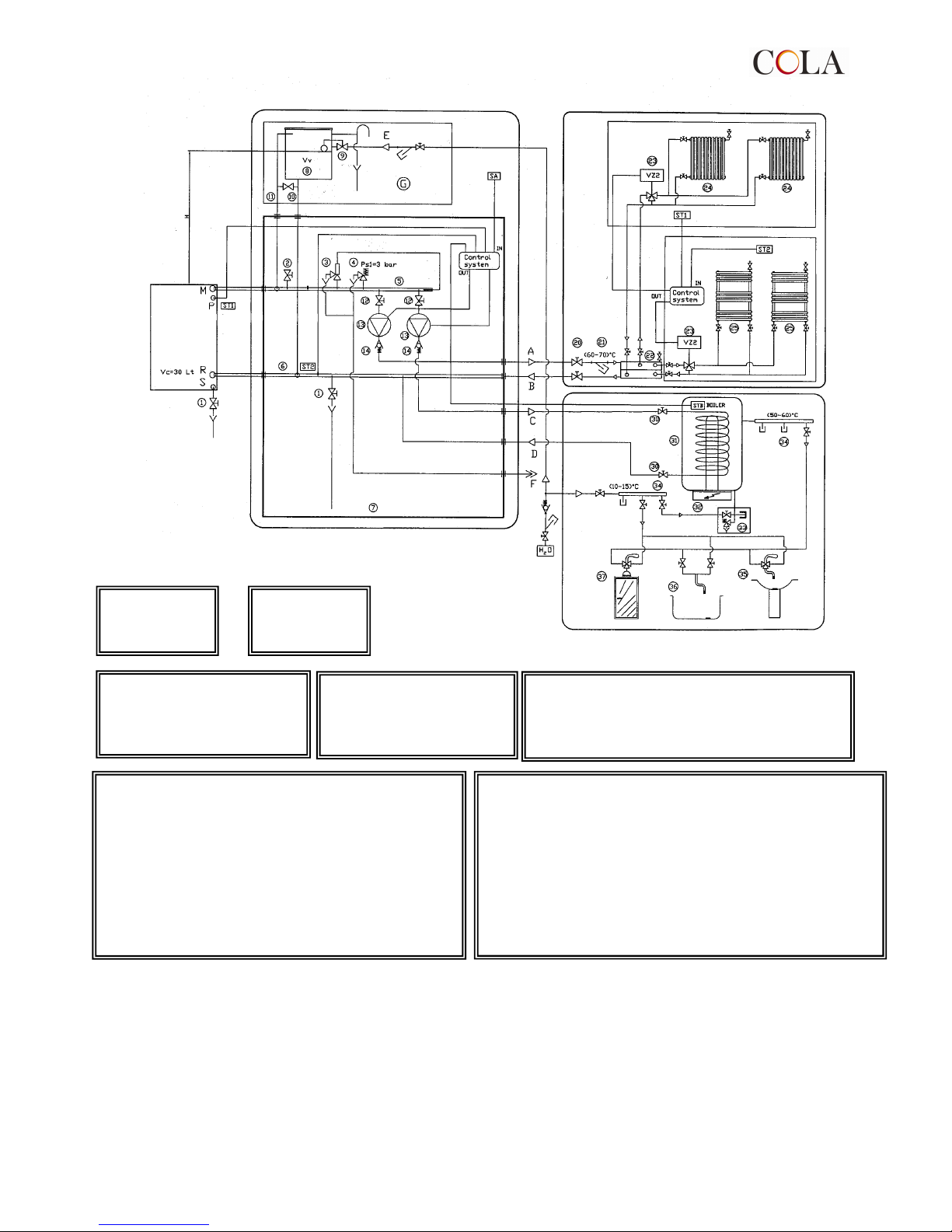
An example of a typical installation layout is given below.
It is provided only as an example, without any responsibility on the part of the Manufacturer.
398
685
691
685
A
D
B
C
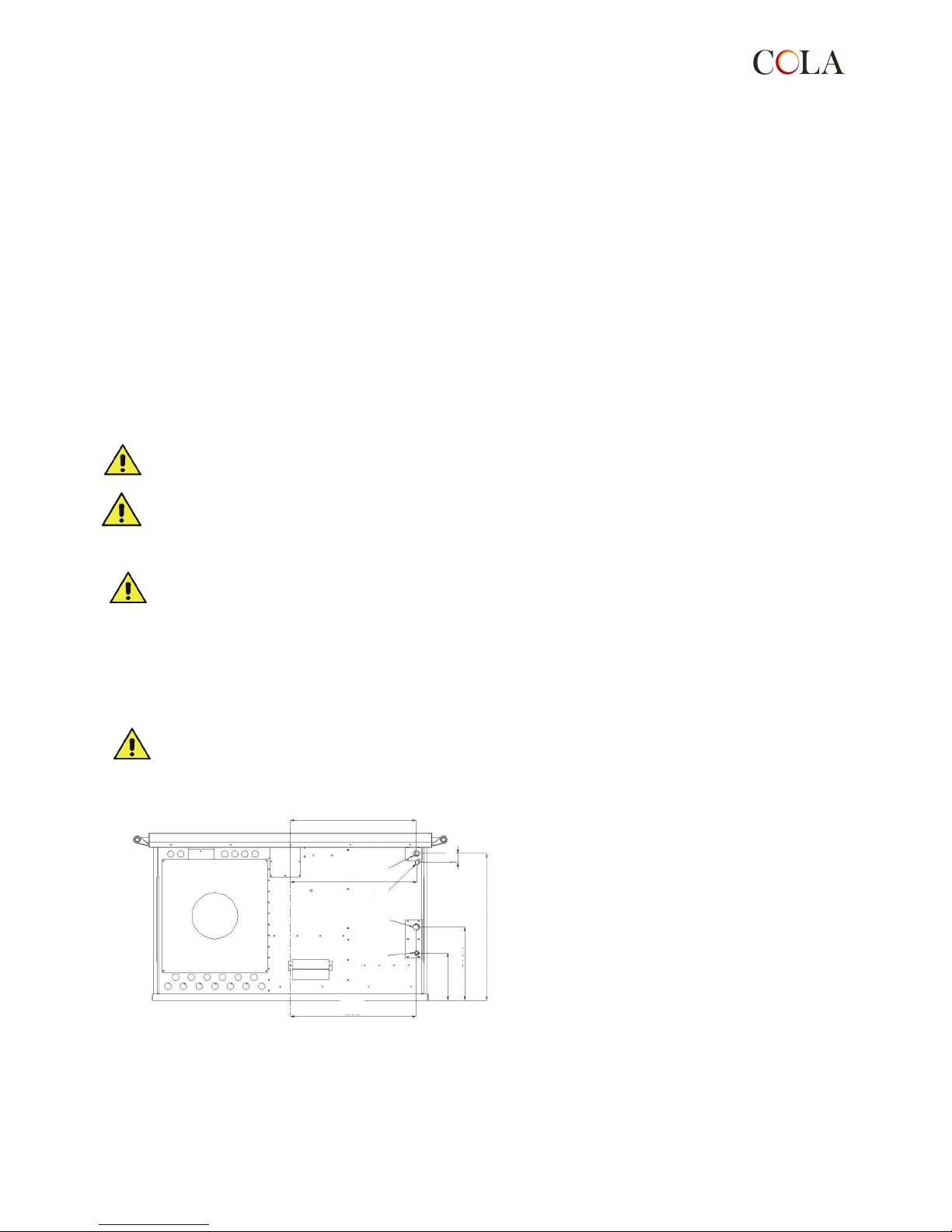
A. system delivery (1”);
B. system return (1”);
C. boiler drain (1/2”);
D. probe pocket connection (1/2”)
Fig. 2 Emmanuelle heating stove plumbing
connections
Page 9
8 T.Emmanuelle
M - delivery F 1”
R - return F 1”
P - hole for probe pocket F ½ “
S - drain F ½ “
SUPPLY Water system
E – connection M ½ “
Water drain in overpress. – temp.
F – connection M ¾ “
1st CIRCUIT
heating
A - delivery M 1”
2nd CIRCUIT
DHW
C - delivery M ½ ”
(G)
External circuit to be created at the customer's premises
Vc = volume of water in combustion chamber
Vt = volume of water in pipes
Vv = volume of water in expansion tank Vv = 0.05 (Vc + Vt)
H > pump ( H greater than head h of circulating pump)
KEY - WOOD-BURNING STOVE SYSTEM
1) Drain cock 9) Filling cock or float valve
2) Heating chamber/circuit air vent 10) Heating chamber filling pipe 1”
3) Temperature relief valve T>95°C 11) Safety and vent pipe 1”
4) Safety valve P max. 3 bar 12) Shutoff cock
5) Delivery manifold 1” 13) Electric circulating pump
6) Return manifold 1” 14) Non-return valve
7) System-door box (SA) Room temperature probe
8) Open expansion tank (ST1) delivery temperature probe
(ST2) return temperature probe
KEY - DHW AND HEATING SYSTEM
(20) System shutoff cock (30) Boiler shutoff cock
(21) Filter in line (31) Water storage boiler 80-115 L
(22) Hydraulic manifold (32) Supplementary heater
(23) Zone solenoid valve (33) Filling and safety assembly
(24) Radiator (34) Distribution manifold
(25) Heating equipment (35) Sink with mixer
(ST1) zone temperature probe 1 (36) Bathtub with taps
(ST2) zone temperature probe 2 (37) Shower with mixer
(STB) Boiler temperature probe
Fig. 3 Example of plumbing system
Wood-fired
heating
chamber
Page 10

Page 11
9 TRMEmmanuelle
Roof
slope
(α)
(α) (α)
(α)
Distance A H
15° 1.00 m
30° 1.30 m
45° 2.00 m
60°
More than 1.85 m
2.60 m
Important:
Before lighting:
1- Make sure there is water inside the heating stove; never light the heating stove without water inside it: the
irregular stresses could cause breakage of the boiler;
2- Check the power;
3- After a long idle period, make sure the circulating pump works;
4- In summer the heating stove should not be lit, or can be lit only with a moderate flame and only if elimination
of the heat is ensured with a storage tank or heat exchanger.
5- The heating stove must be provided with a control panel or electrical equipment (accessory by request) able
to correctly manage normal and emergency operation. It must interface with the various sensors and pumps,
and precisely in the minimum configuration with pump activation thermostat, recirculating pump, buzzer and
acoustic alarm;
6- the system must be provided with:
a-temperature relief valve, with respective connection to the drain;
b-safety valve, set to 2.7/3 bar to prevent the heating chamber from exceeding the max. test pressure.
The thermostat that activates the circulating pump must be set to 55-60°, in order to prevent
condensation inside the combustion chamber.
2.8 Advice on flues and connections
Flues must be made from suitable materials and perfectly insulated, with characteristics that prevent
temperature decreases.
The inner walls must be perfectly smooth without any narrowing or protrusions along the entire length, so as not
to create friction or vortices in the smoke which could cause a considerable reduction in draught.
Any cleaning and inspection doors must be perfectly closed during operation.
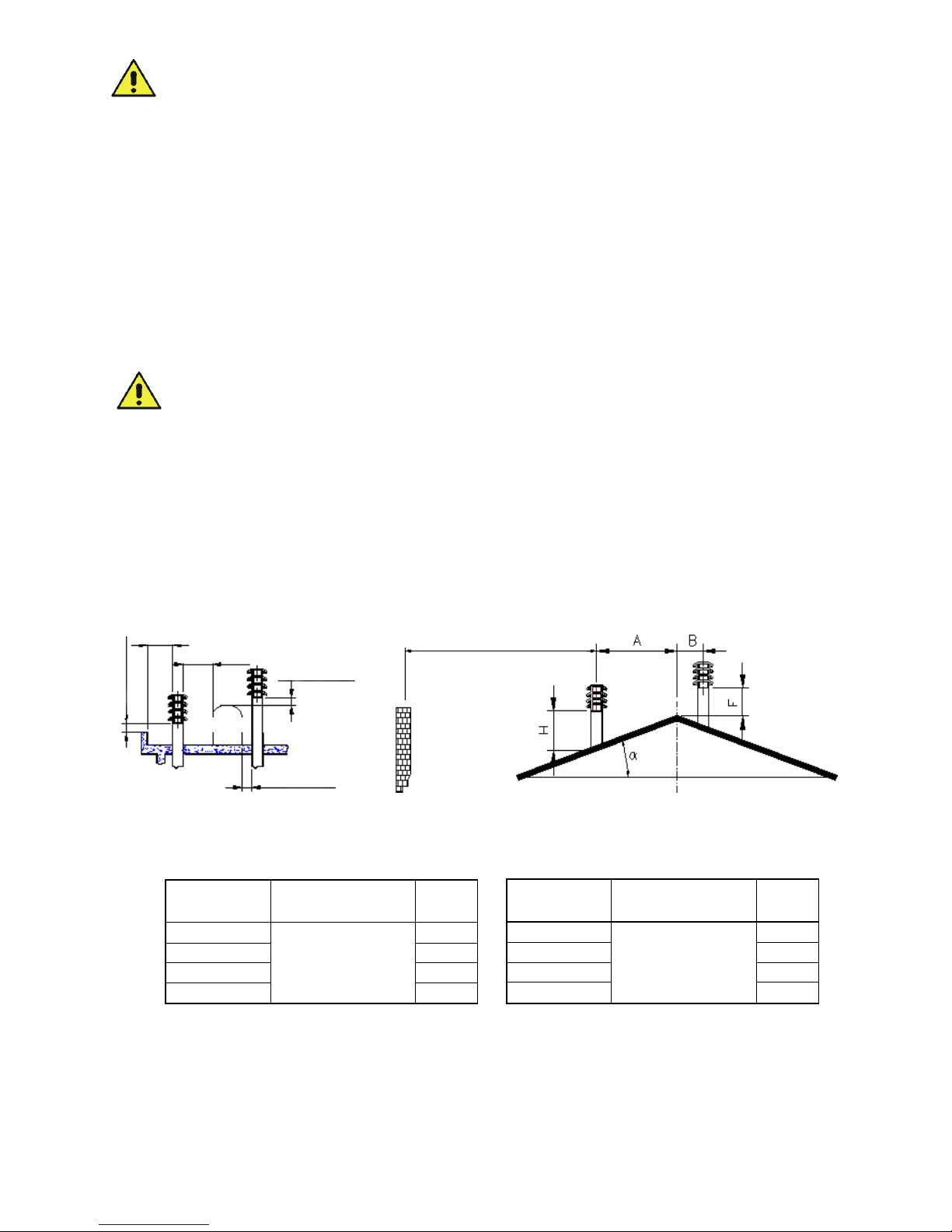
The flue outlets must be 0.5 m higher than any obstacles within a radius of 10 m and must end with chimney
caps or cowls having a useful outlet cross section of at least double that of the flue.
The following two figures give the data regarding the distances and positioning of chimney caps in conformity
with the provisions of UNI 10683/98.
Obstacle
Less than 5
m
Min 0.5m
Min 0.5m
Min 0.5m
The chimney outlet must be at least
0.5 m higher than any obstacle
within a radius of 10 m.
fig. 4 Chimney cap positioning and distances
UNI 10683/98 tables
Roof
slope
(α)
(α) (α)
(α)
Distance B H
15° 0.50 m
30° 0.50 m
45° 0.50 m
60°
Less than 1.85 m
0.50 m
Page 12
9 T.Emmanuelle
Before connecting a heating stove to an existing chimney, in addition to complying with that described above,
make sure there are no
openings or cracks where air
could enter and cause a
temperature decrease
affecting the draught.
Also make sure there are no
hindrances caused by foreign
bodies or a build-up of soot.
The first connection section
leaving
the stove should be vertical,
whereas the flue connection
to the chimney (which goes
to the chimney cap) must
only enter by a few cm, so as
not to reduce the cross
section of the flue.
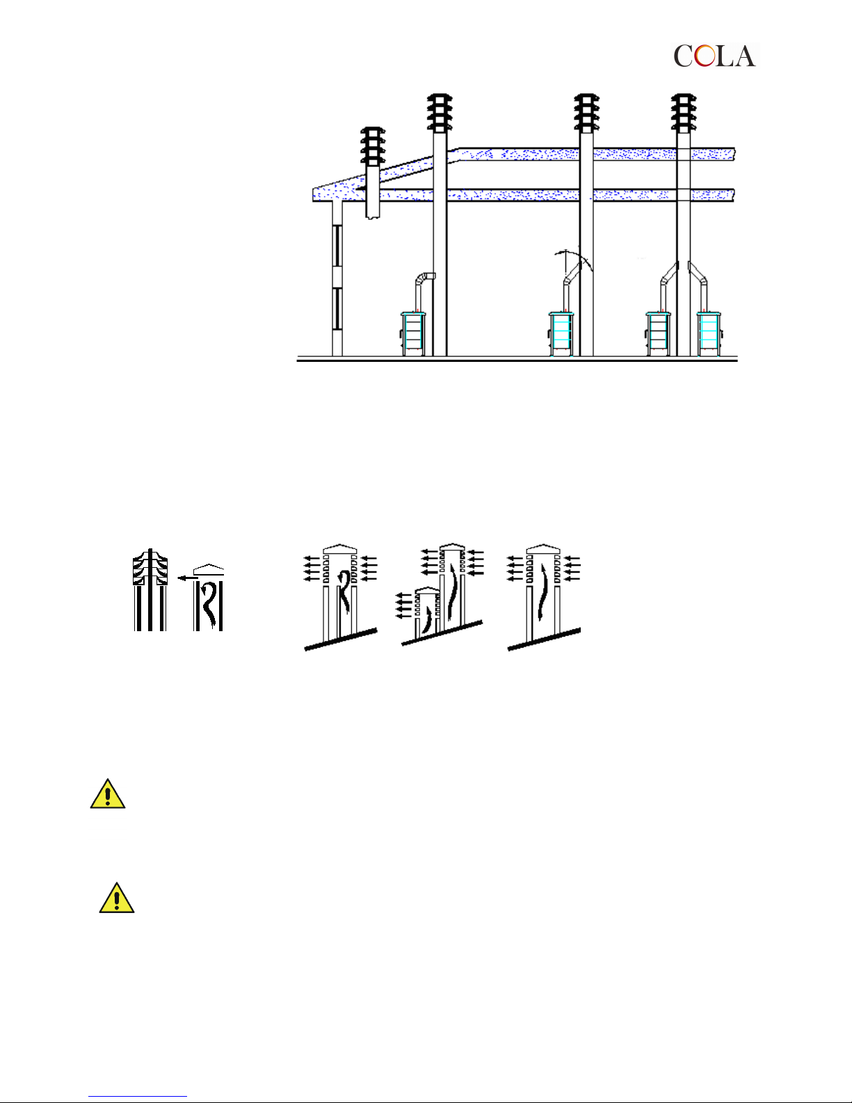
If the flue is not perpendicular
to the chimney it is advisable to make the connection with special steel fittings that allow a maximum slope of
45°.
If the walls and ceiling are made of flammable materials, the parts in contact with the flue must be suitably
insulated. All connection joints must be carefully sealed, in particular where the connection enters the flue.
If there are several heating stoves in the same home, each must have its own flue. It is inadvisable to make
openings in the flue for other appliances, since the draught could be negatively affected.
According to Standard UNI 7429, the chimney cap must meet several requirements; above all, it must have a
useful outlet cross section at least double that of the flue. It is also advisable to install an “antiwind" cap that
guarantees fume exhaust even in the presence of strong horizontal winds.
3– STOVE USE
3.1 Introduction
Never leave children unsupervised in the vicinity of the stove; the risk of burns caused by the hot parts is very
high.
Also:
- never use the heating stove with the ash door and/or fire door open;
- do not store firelighters or other easily combustible materials in the vicinity of the stove;
- do not try to move or lift the stove by the handles.
3.2 Startup
Do not light the heating stove without water inside it; the irregular stresses could cause breakage of the
boiler.
When lighting the stove the first time, bad odours may be created, therefore air the room thoroughly.
Light the heating stove with a low flame and allow it operate for about 30 minutes with the oven door open and
the damper in position Z. Then, with the oven door still open, shift the damper to position A and allow the
heating stove to operate for another 30 minutes.
After lighting the heating stove the first time it must operate for many hours with a low flame (air control on ash
door open 30%). The heat can then be increased a little at a time, so that the stove expands slowly and the
paint and putty dry.
NO
NO
yes
MAX 45°
YES NO
NO YES YES
Fig 6 Chimney caps
Page 13

10 T.Emmanuelle
3.3 Lighting and controlling the fire
To light the fire, it is advisable to use small sticks of wood and newspaper, or other means available on the
market (excluding any flammable liquid substance).
During the lighting stage, the air control on the ash door must be fully open and the thermostat in position 5;
once the stove is lit it is used to regulate stove heat output. During this stage it is also advisable to open the
damper by moving the knob to position Z.
When the stove is hot, adjust the primary air as described in the following paragraph and close the damper by
moving the lever to position A.
Never use petrol, alcohol or other flammable liquids to light the fire.
3.4 Adjusting the combustion air
The combustion air and the heating power are adjusted by a revolving control (B) located on the ash door and
the thermostat (G). In addition to the combustion air adjustment, the flue is the most important factor affecting
combustion intensity and therefore the cooking and heating power of your EMMANUELLE heating stove.
The greater the draught, the less combustion air the stove will require, and vice versa.
Optimum combustion conditions are obtained when, on loading wood, the air necessary for combustion
(controlled by the thermostat) enters through the grate.
3.5 Normal operation
Remove the ash from the grate every time before loading fuel. Put 2-3 logs of wood on the bed of embers. The
combustion air is adjusted by turning the air control on the ash the door and the thermostat; despite the large
capacity of the combustion chamber, it is advisable to only load a max. of 2-3 logs at a time. Overloading does
not increase efficiency, but will overheat the stove, damaging it.
3.6 Operation with partial feed
Heat output can be controlled by reducing the combustion air. To guarantee operation for many hours at low
heat, the primary air valve must only be opened at minimum. With partial feed operation, a patina may form on
the glass due to the low temperature in the fire zone.
In any case, a continuous fire with low output is not advisable.
3.7 Using the hob and electric oven
For any information regarding hob use and maintenance, consult the Manufacturer's manual.
3.8 Operation in off season
With outside temperatures above 15°C, the draught m ay be affected, resulting in a decrease in heat output and
therefore flue gases not completely exhausted (smell of smoke in the room). In this case it is advisable to
remove the ash from the grate and increase the combustion air. Put less fuel on the fire and clean the grate
more frequently.
3.9 Wood-fired oven operation
The wood-fired stove has a static oven with capacity of 42 litres, covered entirely in stainless steel sheet and
provided with 2 racks for holding trays.
A thermometer for controlling the temperature inside the wood-fired oven is installed on the glass of the
enamelled door.
When the stove is lit for the first time, the wood-fired oven should only be used after 1-2 hours operation at 200250°C with the oven door left ajar to eliminate fum es produced by manufacturing process residuals such as
grease, oil and sealants.
To reach adequate cooking temperatures, make sure the damper lever is in position “Z”
and increase the primary air if necessary.
Clean the wood-fired oven every time it is used, following the instructions given in the section on cleaning.
The wood-fired oven must only be used for its intended purpose, i.e. for cooking food; any other use is
improper and potentially dangerous .
Page 14

11 T.Emmanuelle
3.10 Idle period
If the stove is not going to be used for a long period, it is advisable to store it in a safe and protected place.
To best preserve the stove:
- carefully clean it, and replace any damaged parts if necessary;
-
cover the stove to protect it from dust.
4 – ROUTINE STOVE CLEANING AND MAINTENANCE
Good maintenance will help improve the operation, efficiency and service life of the heating stove.
Every day, before lighting the fire, remove any unburnt residuals on the grate and the ashes in the ash pan
zone.
4.1 Removing the ash
The EMMANUELLE stove has a removable grate that should be cleared of ash using the poker provided, every
time before loading wood.
Make sure to periodically empty the ash pan, since the accumulation of ash under the grate hinders the flow of
combustion air. Otherwise the grate will overheat and may become damaged.
To prevent the risk of fire, allow the ashes to cool outdoors in a metal container or in the stove and
eliminate them in compliance with current local regulations.
4.2 Cleaning the glass
The glass can be cleaned using a damp cloth and normal non-abrasive detergents.
Remove any encrustations with suitable detergents, before they become dry.
The ceramic glass can withstand temperatures of around 750°C: in case of breakage, it is advisable to replace it
with another original glass supplied by Cola.
The glass must only be cleaned when the stove is cold.
4.3 Stove cladding maintenance
Clean the cladding only when the stove is cold.
COLA ceramics are handicraft production and therefore may have minor surface imperfections such as tiny
spots or slight colour differences.
It is advisable to use a soft dry cloth to clean the ceramic surfaces; the use of detergents could highlight any
imperfections.
4.4 Cleaning the cast iron hotplate
Before lighting the stove for the first time, make sure to carefully clean the hotplate with hot soapy water, rinse
with clean water and dry.
Before first use and after cleaning, the hotplate should be preheated for about half an hour with the wood-fired
oven door open and the damper lever in position A.
For regular cleaning of the cast iron part of the hotplate, it is advisable to use slightly abrasive materials (e.g.
sandpaper or steel wool), rubbing in the direction of the surface finish.
At the end of the season it is advisable to apply a film of olive oil or neutral vaseline on the cast iron hotplate to
protect it.
4.5 Cleaning the wood-fired oven
It is advisable to clean the wood-fired oven when half-cold or cold and every time after it is used, to prevent
grime forming on the surfaces.
To clean the stainless steel surfaces of the wood-fired oven, use a non-abrasive detergent with a soft cloth,
rinsing thoroughly to remove all traces of detergent which could otherwise contaminate food or cause corrosion.
To clean the baffle located under the oven, open the stove oven door, remove the steel plate and clean.
4.6 Cleaning the hob
Clean the hob only when cold. The stainless steel and painted parts must be cleaned with lukewarm water and
a non-corrosive detergent, then dried with a soft
cloth. Never use metal scouring pads or detergents containing abrasive substances. All aluminium parts must
only be cleaned with alcohol or degreasing products.
Also regularly clean the flame spreaders and burner caps, making sure to remove grime from clogged holes. Do
not clean the grates in a dishwasher.
Page 15
12 T.Emmanuelle
4.7 Cleaning the flue and baffle.
A reduction in heat output is nearly always due to obstruction of the flue. Also, the escaping of burnt gases with
odours can be a sign of an obstructed flue.
The flue of your heating stove must be cleaned at regular intervals. The amount of soot and the frequency of
cleaning will depend largely on the type of fuel and its use (low or high heat output).
To avoid unnecessary dust, carry out cleaning according to the following instructions:
- clean only when the heating stove is cold;
- close all openings which are not to be cleaned;
- remove the flue pipe and clean outdoors;
- detach and suck the deposits inside the heating stove after
removing the hotplate rings and their support;
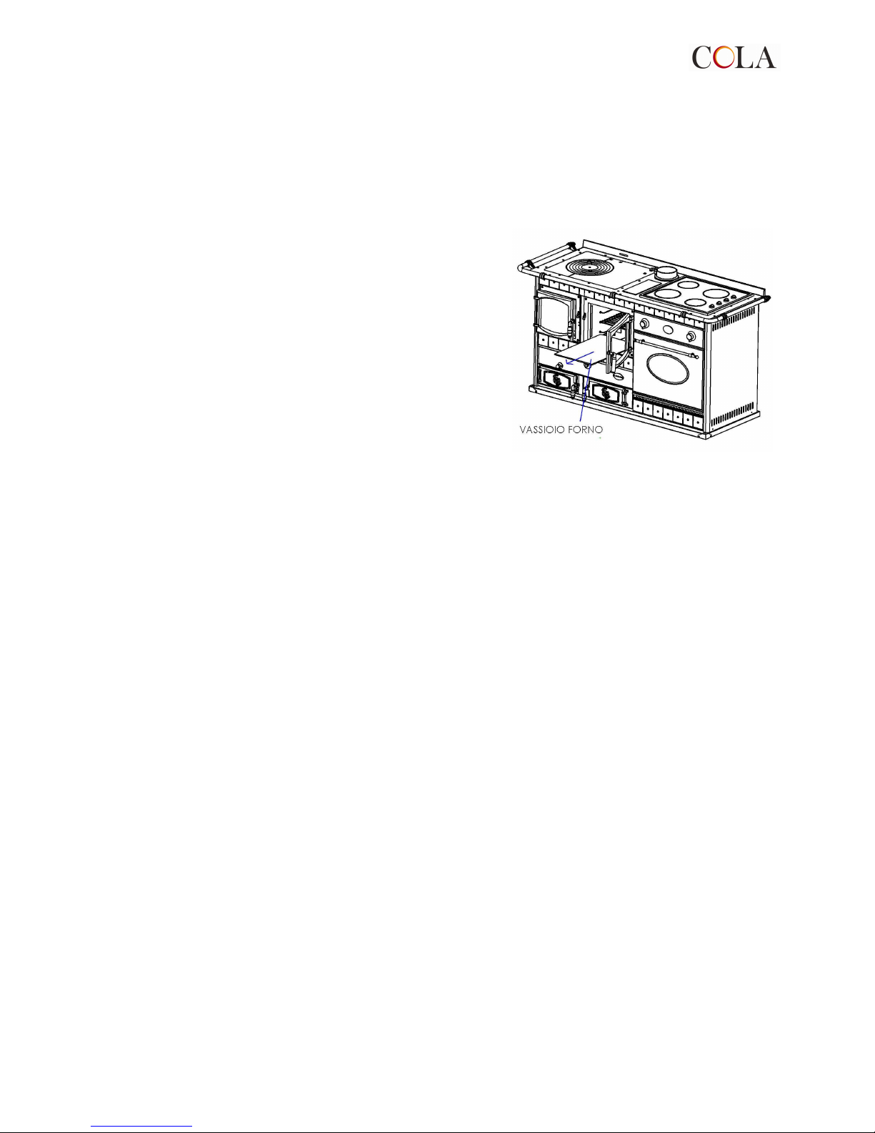
- remove the oven base plate as shown in the figure
opposite, then clean the area underneath, removing any
soot;
- all deposits removed from the grate or the ash pan
must be taken away;
- in any case, detach the pipe from the flue.
5 – TROUBLESHOOTING
5.1 The stove does not work
- Make sure the connector and size of the flue are suitable for the stove's heating power.
- Make sure the flue is constructed in conformity with the current regulations.
- Make sure the flue inspection doors or openings are closed and sealed.
- Make sure no other appliances are connected to the flue.
-
Check the connection to the electrical socket and switching on of the controller
.
5.2 Difficult lighting
- Open the primary air control and the damper.
- Use wood with low moisture content.
- Make sure room ventilation ensures a sufficient amount of oxygen in the air.
-
Make sure the flue is suitable for the stove's heating power
.
5.3 Smoke leaks
- Check the flue draught.
- Make sure the flue pipe connection complies with the seal requirements.
- Make sure the ash does not obstruct the primary air grate.
- Make sure combustion residuals do not block the flue pipe.
- Make sure the primary air control is open.
5.4 The glass gets dirty quickly
- Make sure the fuel is of a recommend type.
- Make sure the wood is properly seasoned and dry.
- Too much fuel in the combustion chamber.
- Check the flue draught.
5.5 Condensate in the heating chamber
-
Make sure the procedure for first lighting has been carried out.
- Make sure the fuel is of a recommend type.
- Make sure the wood is properly seasoned and dry.
- Make sure the flue is insulated and complies with the applicable standards.
- Check the flue draught.
-
Check the pump startup thermostat or the pump activation temperature setting.
5.6 The wood-fired oven does not heat
- Make sure the oven door is properly closed.
- Make sure the bypass damper is closed (pos.1).
- Make sure the fuel burns normally.
- Make sure there is sufficient flue draught.
-
Make sure the combustion fume ducts are clean.
Page 16

14 T.Emmanuelle
5.7 Radiators or heating system inefficient
- Make sure the system shutoff valves are open.
- Vent any air from the radiators.
- Make sure there is water in the system.
- Check the thermostat and its correct position.
-
Check the controller power supply, that the button is ON, the pump works and the activation temperature
(50-60)°C.
5.8 The electric fan oven does not work
- Check the electrical connection
- Check correct operation of the controls, referring to the specific enclosed ILVE manual.
- If the oven still does not operate correctly, switch it off, disconnect the power supply and contact the ILVE
service centre.
5.9 The gas hob does not work
- Check the connection to the gas supply pipe.
- Check correct operation of the controls, referring to the specific enclosed ILVE manual.
- If the oven still does not operate correctly, switch it off, turn off the gas supply
- By closing the main gas cock and contact the ILVE service centre.
6– ENCLOSURES
6.1 Warranty certificate
For the warranty terms contact the importer or the authorised agent.
The product warranty is cancelled in case of any problem, breakage or accident due to non-compliance
with the instructions given in this manual.
The company reserves the right to make technical or aesthetic modifications to the products at any time without notice.
The drawings, measurements, diagrams and any other configurations are given only by way of example.
Page 17
15 T.Emmanuelle
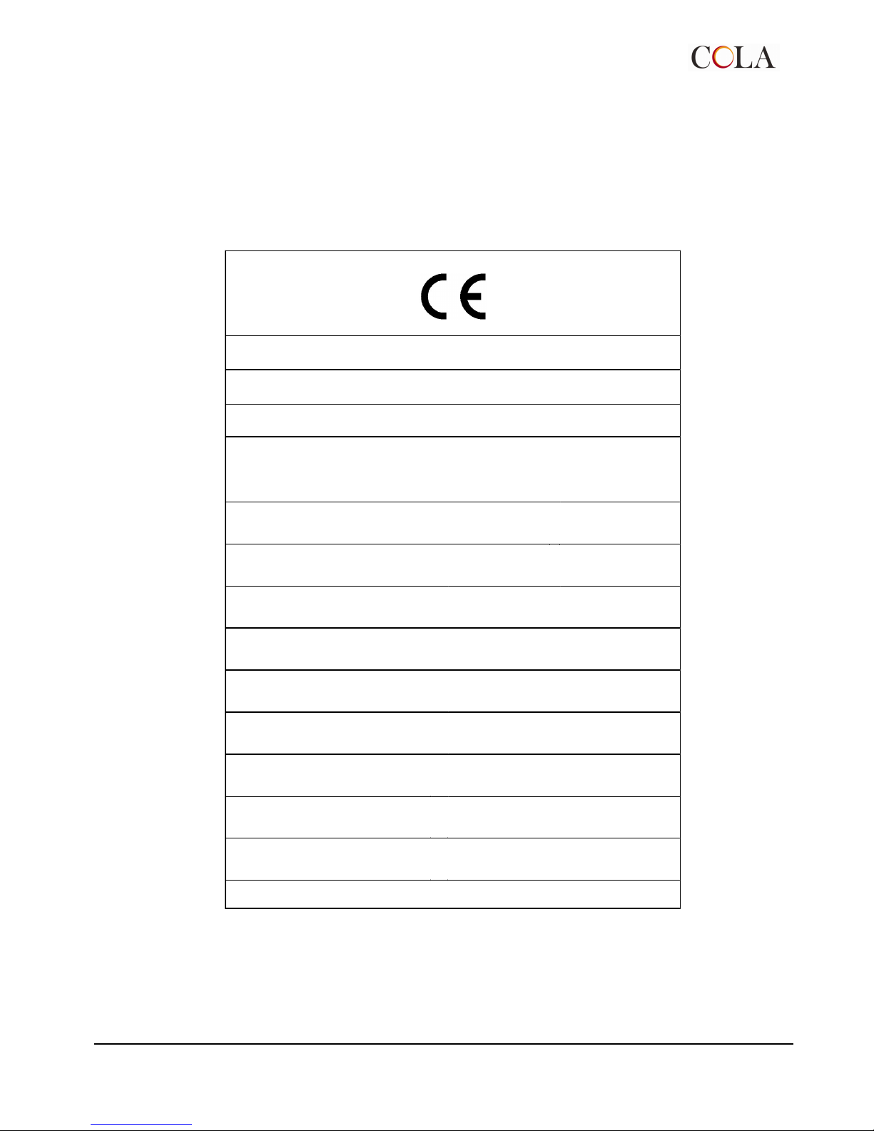
6.2 "CE" marking information
INFORMAZIONI MARCATURA CE
CE MARKING INFORMATION
Cola
07
EN 12815: 2001 + A1: 2004
Termocucine a combustibile solido
Residential cooker fired by solid fuels
Ref. TERMOJOHANNA COMBY – TERMOJOHANNA - TERMOEMMANUELLE
Distanza minima di sicurezza da materiali infiammabili
Minimum safety clearance distance from combustible materials
(rear – right/left side – floor)
:
200-200-0 mm
Emissioni di CO al 13% O2 nei prodotti di combustione
Emission of CO to 13% O2 in combustion products
:
0,674 %
Pressione operativa massima
Maximum operating pressure
: 2 bar
Temperatura gas di scarico
Flue gas temperature
: 283 °C
Potenza termica nominale
Nominal heat output
:
total 27, 0 kW
water heat 21,5 kW
space heat 5,5 kW
Rendimento
Energy efficiency
: 73 %
Tipi di combustibile
Fuel types
:
Legna in tronchetti
Wood logs
Potenza elettrica
Rated input power
:
180 W
Tensione nominale
Rated voltage
:
230 V
Frequenza nominale
Rated frequency
:
50 Hz
 Loading...