

Coiler Pisces, PS-2200 Product Manual
Pisces Digital
ICS Repeater
Product Manual

Pisces Product
Manual
Page 2 of 24
Edition
Edition 1.2, December 22, 2012.
Copyrights
The information contained herein is the property of Coiler Corporation. No
part
of this document may be reproduced or transmitted in any form or by
any
means, electronic or mechanical and for any purpose without the prior
written
permission of
Coiler.
Copyrights © 2012. All rights
reserved.

Page 3 of
24
Pisces Product
Manual
1. About This Manual
This product manual is produced for the use of Coiler’s Pisces (PS) Digital ICS
Repeater by Coiler personnel, licensees and customers.
The Pisces Digital ICS Repeater has the most innovative technologies to simplify the
installation process.
Please first refer to the single sheet installation guide
. This
manual covers the functions of the Pisces (PS) in detail with OMT instructions
(Section 8) and is needed only when the information on the single sheet installation is
insufficient.
Due to the continued progress in methodology, design and manufacturing of
our
products, the contents of this document are subject to revision without any
notice.
Coiler assumes no legal responsibility for any error or damage resulting from the
use
of this
document.
Your comments can assist us in improving our products and services. Please
address
them to Coiler at any
time.
Address : 8F-4, No. 75, Sec. 1, Xintai 5th Rd, Xizhi Dist. New
Taipei City 221,
Taiwan (R.O.C.)
Phone : +886 2 2698
2618
Fax : +886 2 2698
2629
Web site :
www.coiler.com.tw
Email :
sales@coiler.com.tw

Page 4 of
24
Pisces Product
Manual
2. Table of Contents
1. About this Manual .................................................................................... 3
2. Table of Contents ..................................................................................... 4
3. Safety Instructions .................................................................................. 5
4. Package Contents & Parts Identification ......................................... 6
5. Product Introduction ............................................................................... 7
5.1. Product Features .................................................................................... 8
A. Isolation Cancellation System ....................................................... 8
B. Automatic Gain Adjustment .......................................................... 8
C. Automatic Gain Control ................................................................ 8
D. Auto Shut Down & Auto Turn On .................................................. 8
5.2. LED Indications ...................................................................................... 9
5.3. Available Optional Accessories ............................................................ 10
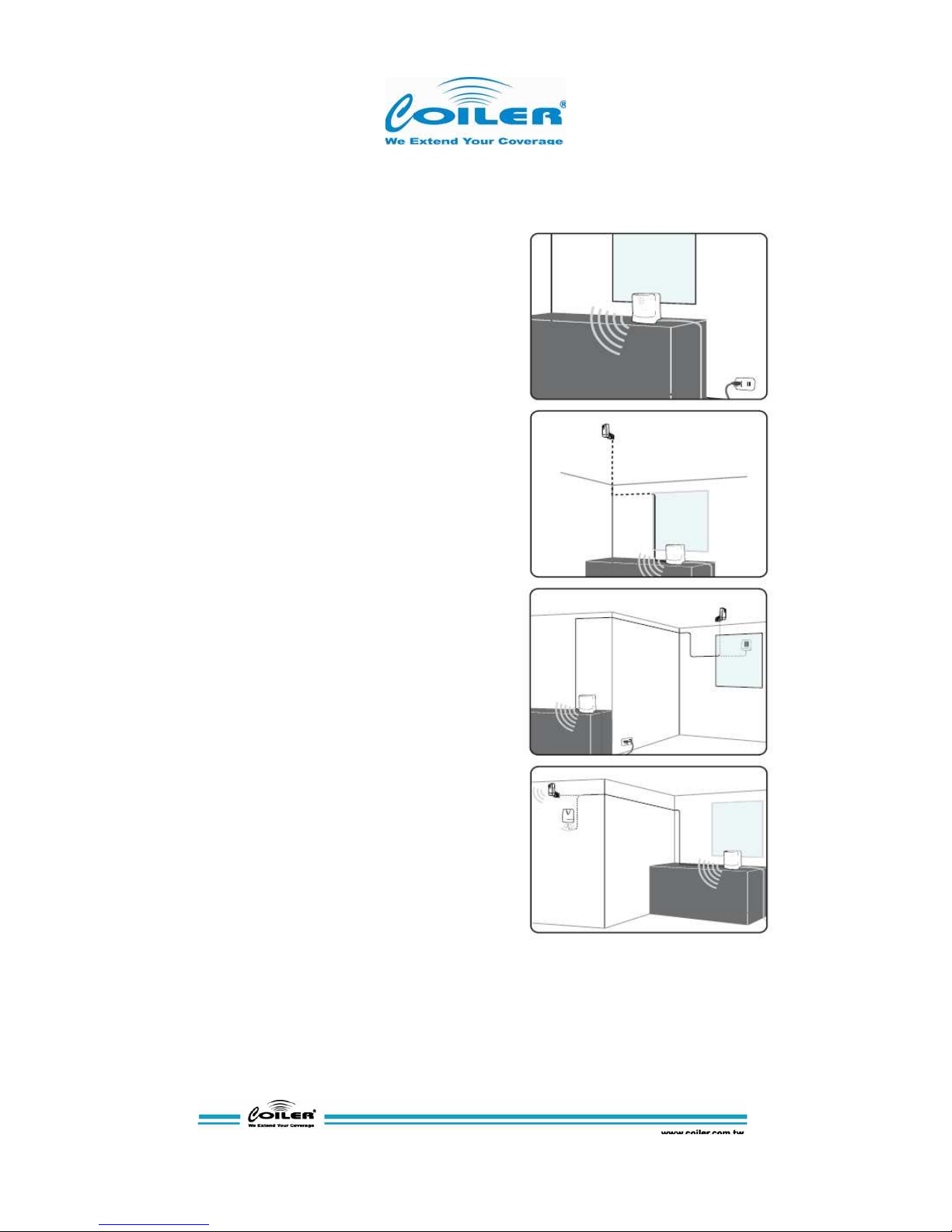
6. Installation ............................................................................................... 11
6.1. Standard Package Installation .............................................................. 11
6.2. Utilizing External Donor Antenna .......................................................... 11
6.3. Utilizing External Service Antenna ....................................................... 12
7. Testing ...................................................................................................... 13
8. Accessing the PS with Coiler OMT ................................................... 14
8.1. .NET Framework 3.5 Installation .......................................................... 14
8.2. OMT Installation ................................................................................... 16
8.3. Micro USB Driver Installation ............................................................... 18
8.4. OMT Login ........................................................................................... 19
8.5. Control, Monitor and Alarms .................................................................. 19
A. Admin Screen Shot..................................................................... 19
B. Operator Screen Shot ................................................................. 22
C. User Screen Shot ....................................................................... 23
9. Troubleshooting ...................................................................................... 24

P
isces Product Manual
Page 5
of 24
3. Safety Instructions
Any personnel involved in an installation, operation or service of the Coiler PS Digital ICS
Repeater must understand and obey the
following:
1. Coiler PS Digital ICS Repeaters must be used exclusively for its application described
in
this guide’s product introduction and nothing
else.
2. For your safety, please be aware of power lines at all times during installation and
use.
Please make sure to take appropriate safety measures for protection. Contact
with
high-voltage power lines can cause serious injury or
death.
3. Please handle the equipment with care. Mechanical shock due to the dropping
or
mishandling of the repeater can permanently damage sensitive RF
components.
4. The PS Digital ICS Repeater is designed for indoor applications and should be
kept
away from water and
humidity.
5. The primary AC power range for the repeater is AC100-240V. It is possible to damage
the
repeater if the primary AC power is outside this
range.
6. Conducted emissions can only be carried out when the DC cable is less than 3m long. Please
operate the repeater with DC power cable included in the package and not cables longer than
3m.
7. An external lightning protector is recommended when the antenna is installed
outdoors.
8.
The operating temperature of this product should be between 0°C ~ 40°C.
9.
Any repeater, including Coiler’s PS Digital ICS Repeater, will generate radio signals and
thereby give rise to electromagnetic fields that may be hazardous to the health of any
person who is extensively exposed to the signals, and is in the immediate proximity of a
repeater or repeater antennas. Therefore, the minimum distance between the user and/or
any bystander and the radiating structure (antenna) of the transmitter is 50cm.
*Coiler’s PS Digital ICS Repeater complies with or exceeds EMC safety and RF
requirements, as per 1995/5/EC Directive.
P
isces Product Manual
Page 6
of 24
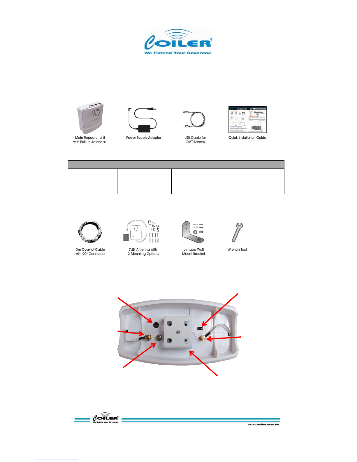
4. Package Contents & Parts Identification
Standard Package:
Accessories Information
AC Adaptor
Model Name
Power Rating
DC Power Cord
EA10521B-060
I/P: 100-240V~1.8A, 50-60Hz; O/P: 6V 6A
120cm
Optional Package Additions:
Base Connections & Components:
Power
Built-in Service
MS Coupler
-10dB from MS
OMT Port
Built-in Donor
Optional
Support Bracket
P
isces Product Manual
Page 7
of 24
5. Product Introduction
Pisces, or PS-2200 is Coiler’s Pico level ICS
(Isolation Cancellation System) repeater. ICS is a
breakthrough technology that cancels isolation up
to 25dB and enables the Pisces to be equipped
with built in donor and service antenna. With
intuitive LED indicators, an average mobile phone
user can simply plug in the power and place the
PS-2200 at the best signal window location for
optimal performance.
In addition to ICS technology, the PS also has
Auto Gain Adjustment (AGA) up to 25dB should
the environment requires attenuation of gain - no
action is required by the user. Standard safety
features such as Auto Gain Control (AGC), Auto
Shutdown (ASD), and Auto Turn-on (ATO) are all
packaged into the PS to ensure network and
product safety.
When signal is weak by the window or when PS
would not be place beside a window, external
donor antenna could be used to ensure the
receptiono of quality signal. When multiple areas
requires service, the PS also has ability to connect
external service antenna(s). Whenever external
antennas are used, wall mount brackets is an
option for better placement and unit stability.
The PS is not only flexible in unit deployment but
also with service frequencies. Coiler’s OMT
software provides the ability for the configuration of
3G service channels to ensure the PS would be
amplifying the signal of a particular operator.
Simple, complete, and versitile, the PS-2200 digital
ICS repeater is an unique offering for carriers to
solve the 3G coverage problems of their clients
instantly.

P
isces Product Manual
Page 8
of 24
5.1 Product Features
The PS Digital ICS Repeater represents some of the most innovative technologies from Coiler. The key
technology that defines the PS is the Isolation Cancellation System (ICS). In addition, the Pisces also
feature technologies such as Automatic Gain Adjustment (AGA), Automatic Gain Control (AGC), Auto
Shut Down (ASD) and Auto Turn On (ATO). Each feature is described in details below.
A. Isolation Cancellation System
Isolation Cancellation System (ICS) is a complex technology. However, the over function can be simply
to the following definition:
All RF signal has three parameters: amplitude (A), phase (Ø), and time delay (T). ICS repeater has a
digital engine that differentiates the real input and feedback signal, then controls and reduces the
amplitude, phase and time delay of feedback signal. Hence echo is cancelled and antennas can be
much closer than repeaters without ICS technology. The formulas below illustrate a 25dB isolation
improvement comparing repeaters without ICS technology and Pisces Digital ICS Repeater.
Repeater without ICS technology: Isolation ≥ Gain + 15dB
Pisces Digital ICS Repeater: Isolation ≥ Gain – 10dB
B. Automatic Gain Adjustment
Working hand in hand with the ICS technology within the Pisces is the Automatic Gain Adjustment
(AGA) with 25dB range. This is a dynamic function that adjusts the gain of the Pisces whenever
isolation becomes insufficient. The full gain of Pisces repeater is 70dB when isolation is 60dB or higher.
When a situation causes the isolation to be lower than 60dB, AGA would reduce the gain immediately
to avoid oscillation. For example, if an object is placed directly in front Pisces repeater on the service
side, this would cause the service signal to feedback to donor and reduce the isolation value. In this
case if isolation becomes 50dB, then AGA would reduce the gain of the repeater by 10dB to avoid
oscillation. Maximum attenuation of AGA is 25dB, which means the Pisces repeater would adjust
automatically for best performance as long as isolation is high than 35dB.
C. Automatic Gain Control
Automatic Gain Control (AGC) is also a dynamic gain adjustment feature with 25dB of range. AGC
adjust the gain of Pisces whenever the input power is higher than -60dBm. Since the maximum gain of
Pisces is 70dB and the maximum output power +10dBm on the DL, whenever input RSSI is higher
than -60dBm, AGC would make the appropriate attenuation to keep the output power consistent at the
max output power level of +10dBm. Maximum attenuation of AGC is 25dB, which means Pisces
repeater can adjust to any circumstance with RSSI of -35dBm or lower. Pisces would shut down when
input power is -35dBm or higher. The use of repeater should not be required when signal level is that
strong.
D. Auto Shut Down and Auto Turn On
When the input power exceeds AGC range on the DL or UL by 3dB, Pisces would activate its
advanced set safety mechanism: Auto Shut Down (ASD) and Auto Turn On (ATO). ASD is a stage that
temporarily stops the RF function of PS. On the UL it will continuously detect the input power and
resume RF function as soon as the input power reduces to a safe range. For the DL, it will make three
attempts to detect the input power in this temporary stage. If the input power reduces to a safe range
for the PS to operate, the ATO feature would power the repeater back on and restore all functions
promptly. However, if the input power remains too great and dangerous for the network, it will then shut
down completely. In such the signal is too strong for the usage of Pisces repeater.
Note: shutdown level of Pisces is at +13dBm (3dB higher than maximum output power), which
translates to an input power of -32dBm after full AGC attenuation).
 Loading...