

Coiler AT-2200 User Manual
AT-2200
Band Selective
Pico Indoor Repeater
User Manual
V1.01

Atom Series Installation and Operation Manual
2
Edition
Second Edition, May 2009.
Copyrights
The information contained herein is the property of Coiler Corporation.
No part of this document may be reproduced or transmitted in any form
or by any means, electronic or mechanical and for any purpose without
prior written permission of Coiler.
Copyrights © 2009. All rights reserved.

Atom Series Installation and Operation Manual
3
1. About this Manual
This installation guide is produced for the use of Coiler’s AT-2200
Repeater by Coiler personnel, licensees and customers.
Due to the continued progress in methodology, design and
manufacturing of our products, the contents of this document are subject
to revision without any notice. Coiler assumes no legal responsibility for
any error or damage resulting from the use of this document.
Your comments can assist us in improving our products and services.
Please address them to Coiler at any time.
Address :
8F-4, No. 75, Sec. 1, Hsin Tai Wu Road, Hsi-Chih City
(221), Taipei Hsien, Taiwan.
Phone : +886 2 2698 2618
Fax : +886 2 2698 2629
Website : www.coiler.com.tw
Email : sales@coiler.com.tw

Atom Series Installation and Operation Manual
4
2. Table of Contents
1. About this Manual ..................................................................3
2. Table of Contents...................................................................4
3. Safety Instructions .................................................................5
4. Product Introduction...............................................................6
5. Installation..............................................................................8
5.1. Package Contents.......................................................8
5.2. Parts Identification.......................................................8
5.3. Installation of the Main Unit.........................................8
5.4. Installation of the Donor Antenna ................................8
5.5. Installation of the Extended Service Antenna..............8
5.6. Connecting the Cables................................................8
6. Start the Device .....................................................................8
6.1. Switch on the Repeater...............................................8
6.2. Donor RSSI Indication.................................................8
6.3. Gain Adjustment..........................................................8
6.4. Automatic Gain Control (AGC) ....................................8
6.5. Alarm LED...................................................................8
7. Troubleshooting .....................................................................8

Atom Series Installation and Operation Manual
5
3. Safety Instructions
Any personnel involved in the installation or operation of the Coiler
AT-2200 Band Selective Repeaters must understand and obey the
following safety instructions:
1. The Coiler AT-2200 Band Selective Repeaters must be used
exclusively for its application as described in this guide's product
introduction and nothing else.
2. For your safety, please be aware of power lines at all times during
the installation and use of the repeater. Please ensure to take
appropriate safety measures for protection. Contact with
high-voltage power lines can cause serious injury or even death.
3. Please handle the equipment with care. Mechanical shock due to
the dropping or mishandling of the product can permanently
damage sensitive RF components. Falling parts can also cause
serious personal injury.
4. The AT-2200 Band Selective Repeaters are designed for indoor
applications only and should be kept away from water and humidity.
5. The primary AC power range for the repeater is AC110-240V. It is
possible to damage the repeater if the primary AC power is outside
this range.
6. An external lightning protector is recommended when the donor
antenna is installed outdoors.
Atom Series Installation and Operation Manual
6
4. Product Introduction
The Coiler AT-2200 Band Selective Repeater is designed to improve
mobile phone signal coverage and enhance reception in indoor areas
where mobile signal is limited or compromised due to construction
structures or natural obstacles. This device is a perfect choice for
network operators seeking a quick and cost-effective coverage solution
for small indoor areas. As an additional benefit, the AT-2200 will fit
perfectly into any home or office setting due to its modern and stylish
design.
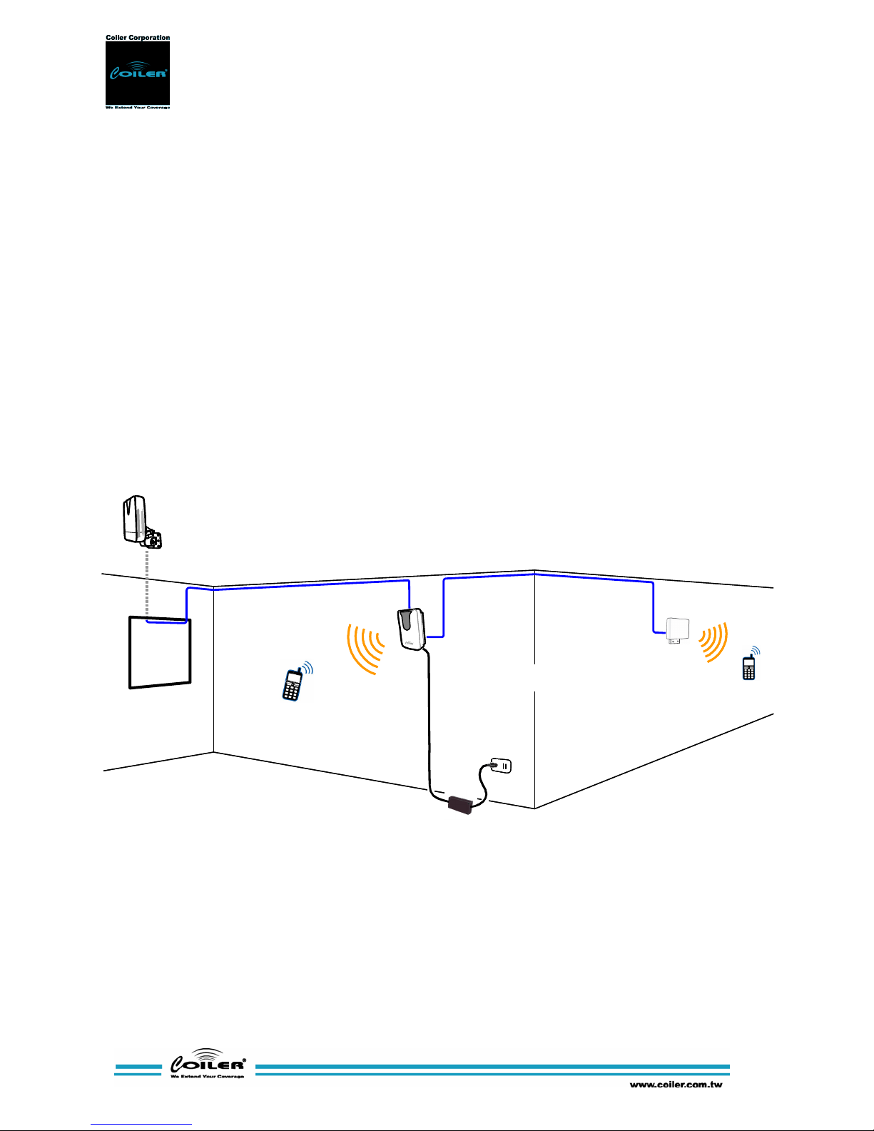
This device is designed as a bi-directional amplifier that receives and
amplifies signals from one or more base stations and retransmits the
signals to one or more mobile phones. The repeater also receives
signals from one or more mobile phones, amplifies and retransmits the
Donor
Antenna
(Outdoor)
Indoor
Repeater
Extended
Service
Antenna
Optional

Atom Series Installation and Operation Manual
7
signals to the base stations.
This repeater will only amplify the operators’ signal, as high SAW filter
selectivity provides sharp, out of band rejection. It offers an Auto Gain
Control function designed to protect the system against oscillation and
interference with base stations. To enable easy installation, the AT-2200
Band Selective Repeater features an LED signal strength display and
alarm LED.
Atom Series Installation and Operation Manual
8
or
5. Installation
Before installing the repeater, please check the package contents.
Please contact the dealer if any part is missing. Also, please read
Chapter 1 ‘Safety Instructions’ closely.
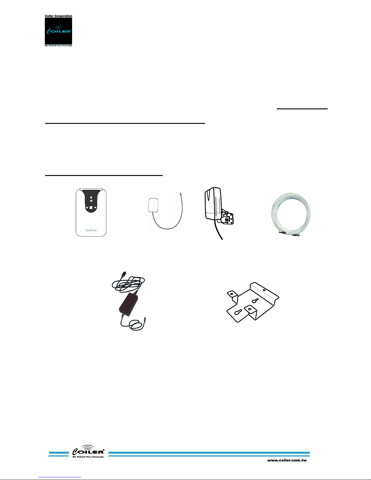
5.1. Package Contents
Standard package contents are displayed in the pictures below.
Package contents may vary.
Power Adaptor
INPUT: 100~220V (AC), 47~63Hz
OUTPUT: 6.0V (DC), 2A
Repeater Unit
15m of RF Cable
Donor Antenna
Wall Mounting Bracket
& Screws
 Loading...