

CohuHD Costar 4220HD, 4260HD Operation Manual
RISE™ Series
4220HD
Dome Positioning System
4260HD
Camera Positioning System
Operation Manual 6x-1119A
www.CohuHD.com

- 2 -

Table of Contents
1.0 General Information 5
1.1 About this document 5
1.2 Additional information and documents related to the camera system 5
1.3 Copyright/Intellectual Property Rights Statement 5
1.4 FCC compliance 5
1.5 Support services 5
1.6 Returns 6
1.7 Shipment 6
2.0 Getting Started 7
2.1 Recommended Computer Specifications 7
2.2 System Requirements 7
2.3 Factory Default IP Address and Settings 7
2.4 Factory Default User Names and Passwords 7
2.5 Assigning the Static IP Address 8
2.6 Assigning the New Camera IP Address 10
2.7 Using the RISE Camera Discovery Tool 11
2.8 Accessing the Camera Using Web Interface 13
2.9 Users' Accounts 14
3.0 Operation 15
3.1 Home Page 15
3.2 Control Panel 18
3.2.1 PTZ Control 18
3.2.2 Presets and Tours Control 20
3.2.3 Advanced Control 21
3.3 Setup Panel 22
3.3.1 Image 24
3.3.2 Lens Settings 24
3.3.2.1 Exposure Settings 24
3.3.2.2 Defog Settings 26
3.3.2.3 Advanced Settings 27
3.3.3 Positioner 29
3.3.3.1 Preset Settings 29
3.3.3.2 Tour Settings 31
3.3.3.3 Park Settings 33
3.3.3.4 Positioner Settings 34
3.3.4 Media 36
3.3.4.1 Media Wizard 36
3.3.4.2 Media Utilization 38
3.3.4.3 Profile Settings 39
3.3.4.4 Stream Settings 41
3.3.4.5 Advanced Settings 45
3.3.5 Action Engine 46
3.3.5.1 Action Engine Wizard 46
3.3.5.2 Email Servers 49
- 3 -

3.3.5.3 FTP Servers 51
3.3.5.4 Action Engine Configuration 52
3.3.5.5 Action Engine Settings 62
3.3.6 Users 63
3.3.6.1 User Settings 63
3.3.7 Network 66
3.3.7.1 Network Settings 66
3.3.7.2 Port Settings 68
3.3.7.3 Serial Settings 69
3.3.8 Date and Time 71
3.3.8.1 Date and Time Settings 71
3.3.9 On-Screen Display (OSD) 72
3.3.9.1 OSD Wizard 72
3.3.9.2 OSD Settings 75
3.3.9.3 OSD Banner Settings 78
3.3.9.4 OSD Font Settings 80
3.3.9.5 OSD Sector Settings 81
3.3.9.6 OSD Logo Settings 82
3.3.10 Privacy Mask 84
3.3.10.1 Privacy Mask Wizard 84
3.3.10.2 Privacy Mask Add/Delete 87
3.3.10.3 Privacy Mask Settings 88
3.3.11 Accessories 89
3.3.11.1 Accessory Settings 89
3.3.11.2 Digital IO Settings 91
3.3.12 System 92
3.3.12.1 Information 92
3.3.12.2 Service 92
3.3.12.3 Support 93
3.3.12.4 System Message 93
3.3.12.5 Licenses 93
3.3.12.6 Update Camera Instructions 94
3.3.13 Factory Default Settings 97
3.3.13.1 Factory Default IP Address and Settings 97
3.3.13.2 Factory Default User Names and Passwords 97
3.3.13.3 Image Default Settings 97
3.3.13.4 Positioner Default Settings 98
3.3.13.5 Media Default Settings 98
3.3.13.6 Network Default Settings 99
3.3.13.7 OSD Default Settings 99
3.3.13.8 Privacy Mask Settings 100
3.3.13.9 Accessories Settings 100
3.3.13.10 Date/Time 100
4.0 Warranty 101
- 4 -

1.0 General Information
1.1 About this document
This document contains information on how to configure and operate the RISE™ 4260HD Series camera positioning system and 4220HD Series dome positioning system using the Command Core™ web interface.
Please read this manual carefully prior to installation to prevent any accidental damage or misuse. The manual
is available from the CohuHD website at:
http://www.cohuhd.com/Support/Product-Documentation
The information in this manual is subject to change without notice. Please refer to the above website for the
latest information.
Note: All graphics contained within this document, including screenshots and other displays, are for reference use only and are subject to change.
1.2 Additional information and documents related to the camera system
For information on the 4260HD camera system installation, see Installation manual 6x-1114. The manual is
available from the CohuHD Costar website at:
For information on the 4220HD camera system installation, see Installation manual 6x-1116. The manual is
available from the CohuHD Costar website at:
http://www.cohuhd.com/Support/Product-Documentation
1.3 Copyright/Intellectual Property Rights Statement
Copyright 2015, 2016, 2017 CohuHD Costar, LLC. CohuHD Costar, LLC has intellectual property rights to
technology embodied in the product described in this manual.
CohuHD Costar™, RISE™, and Command Core™ are trademarks of CohuHD Costar, LLC.
1.4 FCC compliance
This equipment has been tested and found to comply with the limits for a Class A digital device pursuant to
Part 15 of the FCC Rules. These limits are designed to provide reasonable protection against harmful interference when the equipment is operated in a commercial environment. This equipment generates, uses, and
can radiate radio frequency energy, and, if not installed and used in accordance with the instruction manual,
may cause harmful interference to radio communications. Operation of this equipment in a residential area is
likely to cause harmful interference, in which case the user will be required to correct the interference at his
own expense.
Operation is subject to the following two conditions:
(1) this device may not cause harmful interference, and (2) this device must accept any interference received,
including interference that may cause undesired operation. Changes or modifications to this device void the
warranty.
1.5 Support services
Please contact the Customer Service Department for technical assistance.
- 5 -

1.6 Returns
This item was thoroughly tested and carefully packed at the factory prior to shipping. Upon acceptance by the
carrier, the carrier assumes responsibility for the item’s safe arrival. If you receive the item in a damaged condition, apparent or concealed, a claim for damage must be made to the carrier.
If a visual inspection shows damage upon receipt of this shipment, it must be noted on the freight bill or
express receipt and the notation signed by the carrier’s agent. Failure to do this can result in the carrier refusing to honor the claim.
When the damage is not apparent until the unit is unpacked, a claim for concealed damage must be made.
Make a mail or phone request to the carrier for inspection immediately upon discovery of the concealed damage. Keep all cartons and packing materials.
To return the product to the factory for service, please contact the Customer Service Department for a Return
Material Authorization (RMA) Number.
Prominently display the RMA number on the outside of the shipping container(s) and on paperwork contained
inside. Give a brief description of why the equipment is being returned and list the symptoms of any problems
being experienced with the equipment.
1.7 Shipment
Important:If the camera needs to be shipped, please use the original packaging material which was
designed to protect the product during transportation. If the original packaging is lost or damaged, please
order a replacement from Customer Service.
- 6 -

2.0 Getting Started
2.1 Recommended Computer Specifications
The following are recommended computer specifications to run and operate a camera system:
l CPU: Intel i7-860S 2.53 GHz or better
l Operating system: Windows 7 or later
l Memory: 4GB DDR3@1066MHz or better
l Hard Drive: 7200 rpm – minimum speed with sufficient free space
l Video card: NVIDIA® GeForce® 9800 GTX+ with 512 MB RAM or better, or high-end ATI Radeon™
HD series
l Monitor: LCD monitor with 1920 x 1080 or better resolution
2.2 System Requirements
In order to test the camera system you need the following items:
Laptop or desktop computer
l 100/1000BASE-T network card installed in the computer
l Use one of the following web browsers:
a. Microsoft Internet Explorer, version 11
b. Mozilla Firefox, version 50.0
c. Google Chrome, version 55.0
l 100/1000BASE-T network switch or hub
l Cat5e cable
2.3 Factory Default IP Address and Settings
The camera is shipped with:
l IP Address: 192.168.2.150
l Subnet mask: 255.255.255.0
l Gateway: 192.168.2.1
2.4 Factory Default User Names and Passwords
The camera is shipped with the user names and passwords shown in the table.
Access Level Username Password
Administrator admin admin
Operator operator operator
User user user
Anonymous anonymous anonymous
Important: Passwords are case-sensitive; usernames are not.
- 7 -
2.5 Assigning the Static IP Address
Important: In order to make changes in network settings in the local machine the user must be logged in as
Administrator. Please contact your local IT department if you do not have Admin privileges.
Set your computer IP address to the same subnet as the camera system IP address:
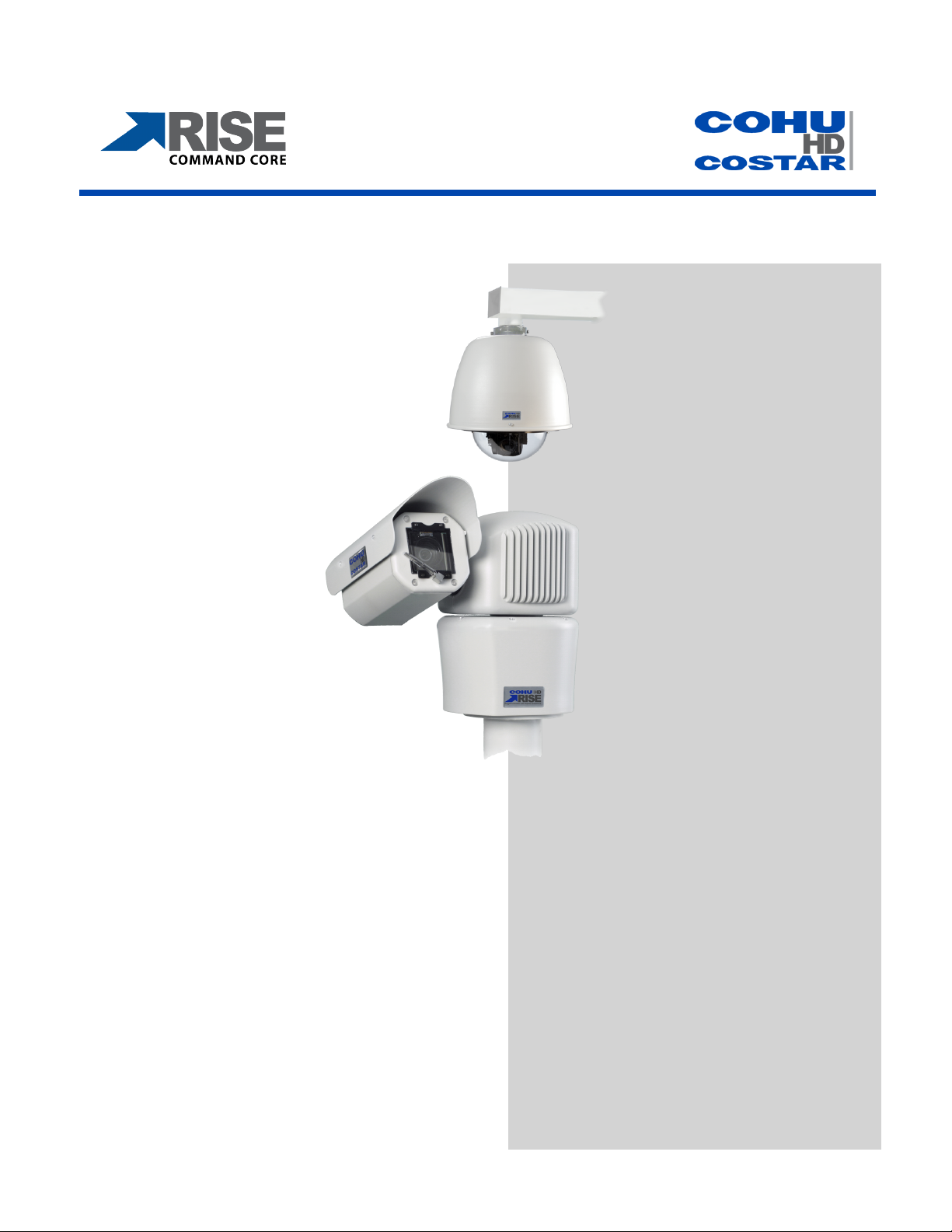
1. Go to Start > Control Panel > Network and Sharing Centers > Local Area Connection.
2. The Local Area Connection Status dialog box opens. Click the Properties button.
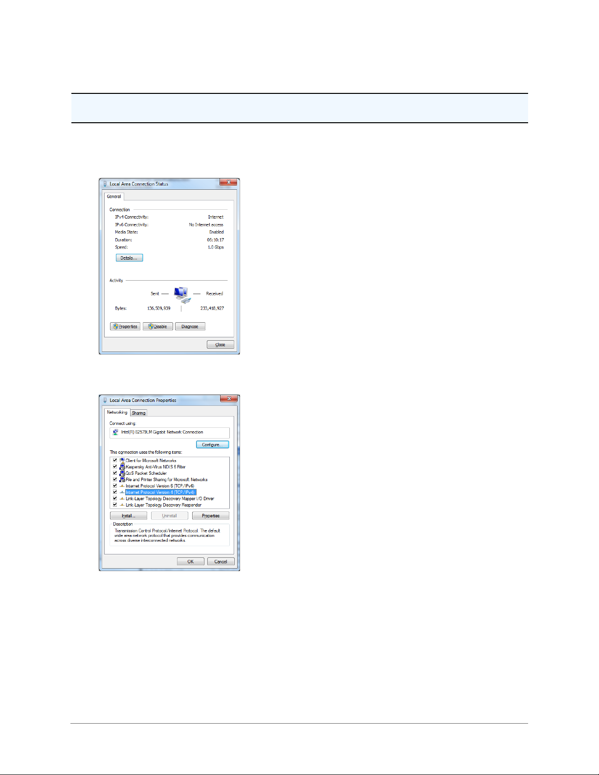
3. The Local Area Connection Properties dialog box opens. In the Networking tab, highlight the Internet
Protocol Version 4 (TCP/IPv4) line. Click the Properties button.
4. The Internet Protocol Version 4 (TCP/IPv4) dialog box opens:
a. Select the Use the following IP Address button in the General tab.
b. Enter IP address: the IP address range is 192.168.2.1 through 192.168.2.254 except
192.168.2.150 (the default address that has been assigned to the camera).
c. Enter the subnet mask: 255.255.255.0.
d. Click the OK button to close the Internet Protocol Version 4 (TCP/IPv4) dialog box.
- 8 -
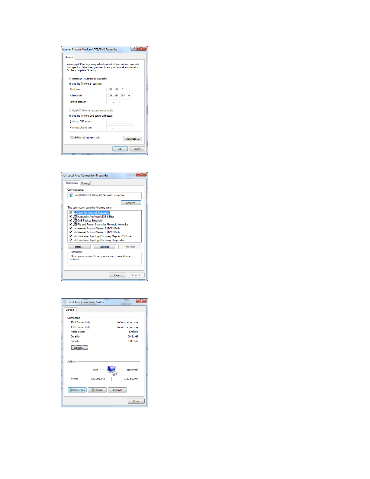
5. Click the Close button to close the Local Area Connections Properties dialog box.
6. Click the Close button to close the Local Area Connection Status dialog box.
- 9 -

2.6 Assigning the New Camera IP Address
No two devices on a single Ethernet network can have the same IP address. Use the following steps to
change a camera IP address before a second camera is added to the subnet.
1. Set your computer IP address to the same subnet as the camera IP address: Setup Panel> Network >
Network Setting.
Important: In order to make changes in camera configuration the user must be logged in as Administrator.
2. Change the camera address. The camera address can be changed manually or through a Dynamic
Host Configuration Protocol (DHCP) server.
Important:Care must be taken when modifying parameters on this page as the changes can make
the camera inaccessible through the network. Consult with your network administrator before starting to assign new network settings to ensure that your camera won’t conflict with other devices.
3. Write down the new camera address to make the camera easy to find later. If the camera IP address
becomes lost, use the RISE Camera Discovery Tool to find the camera on a network. The software is
available as a free download at http://www.cohuhd.com/Support/Software-Downloads. Under RISE
Camera Discovery Tool, click “Download Now”.
- 10 -
2.7 Using the RISE Camera Discovery Tool
1. Download the RISE Camera Discovery Tool. The software is available as a free download at:
http://www.cohuhd.com/Support/Software-Downloads. Under RISE Camera Discovery Tool, click
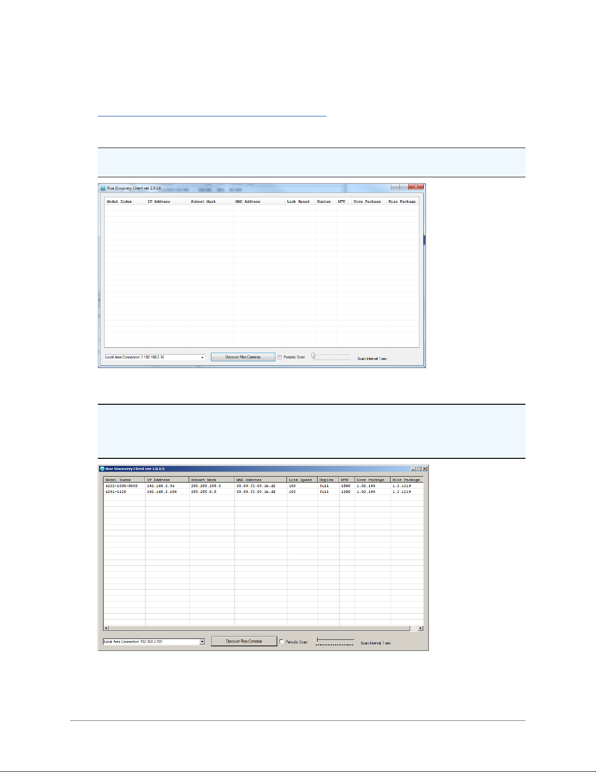
“Download Now”. Run the RiseDiscoveryClient.exe file. Click to start it.The Rise Discovery Client window will be displayed.
Note: The autodiscovery feature uses network broadcast packets and may not work through network
routers.
2. Click on the Discover Rise Cameras button. A window with a list of cameras will be automatically displayed.
Note: Use the MAC Address or Model Index to identify CohuHD cameras. “00-09-f2” identifies cameras as CohuHD cameras. The MAC address of the camera is the serial number of the camera which
can be found on the serial number label. The label location is on the back of the camera head for
4260HD and on the housing for 4220HD.
Periodic Scan: Check the box to enable or disable periodic scans.
- 11 -
Scan Interval: Move the slider indicator to establish a desired scan interval. A minimum interval is one
second.
To schedule scans:
l Check the Periodic Scan box.
l Move the slider indicator to set a scan interval value.
Note: If the Periodic Scan box is unchecked, the scan will be initiated only once.
3. Double-click a row in the discovered cameras grid. That will open your default browser and navigate to
the camera's login page.(See "System Requirements" on page 7 for the supported browsers.) Type the
user name and password.
- 12 -
2.8 Accessing the Camera Using Web Interface
The camera system supports the following browsers:
l Microsoft Internet Explorer, version 11
l Mozilla Firefox, version 50.0
l Google Chrome, version 55.0
Important: Microsoft ActiveX® is required to view and control video if Internet Explorer is used.
Important: In order to make changes in network settings and install ActiveX® controls in the local machine
the user must be logged in as Administrator. Please contact your local IT department if you do not have
Admin privileges.
Upon delivery, the first time you access the camera system for starting a video stream take the following
steps:
1. Log in as a local administrator on your computer.
2. Start the browser.
Note: You may need to set the security level and add the camera system as a trusted site in order to
run a video.
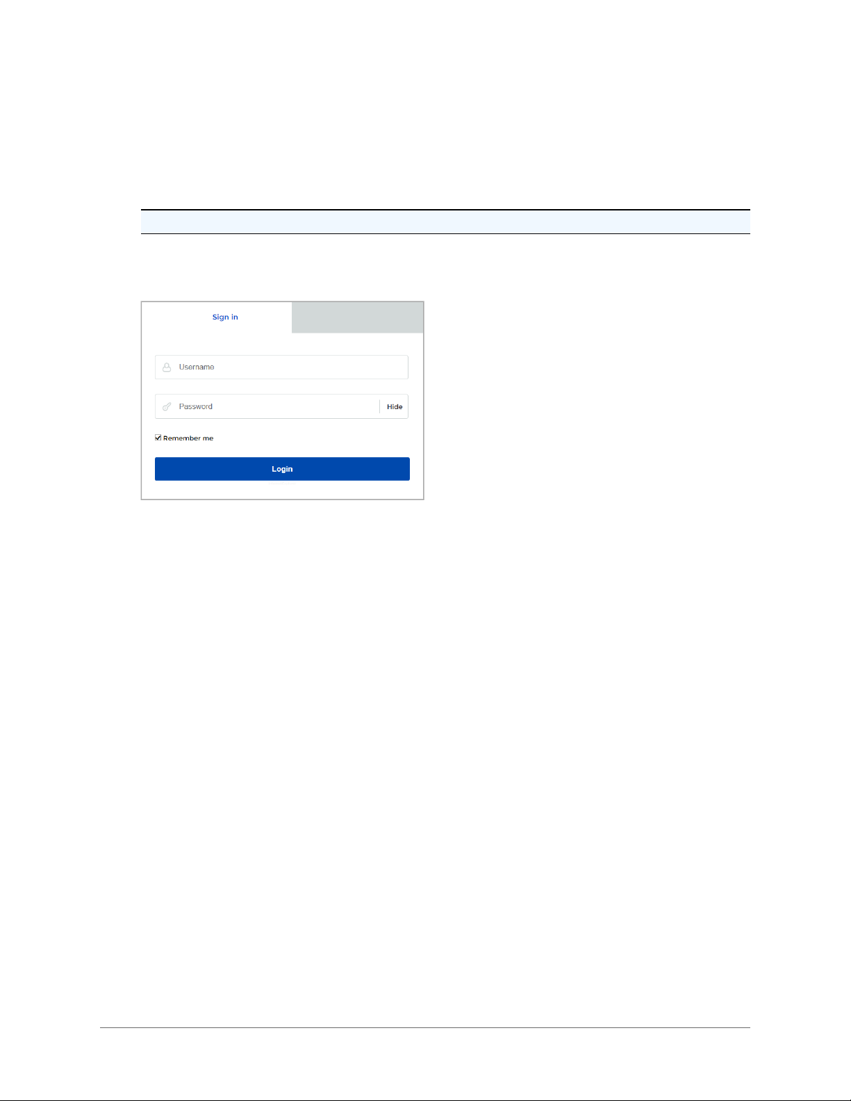
3. Enter the camera IP address in the browser address box. The default address is http://192.168.2.150.
4. The CohuHD Sign In page appears.
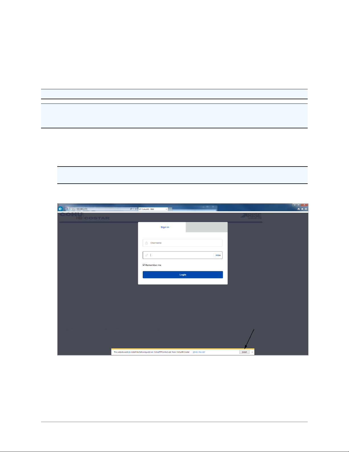
5. For Internet Explorer only: The camera will attempt to install an ActiveX control on your PC. Allow the
camera to install ActiveX control by clicking on the prompt “This website wants to install the following
add-on: CohuRTPControl.cab from CohuHD Costar.” Click the Install button.
6. Type user name and password. Click OK.
See "Factory Default User Names and Passwords" on page 7.
- 13 -
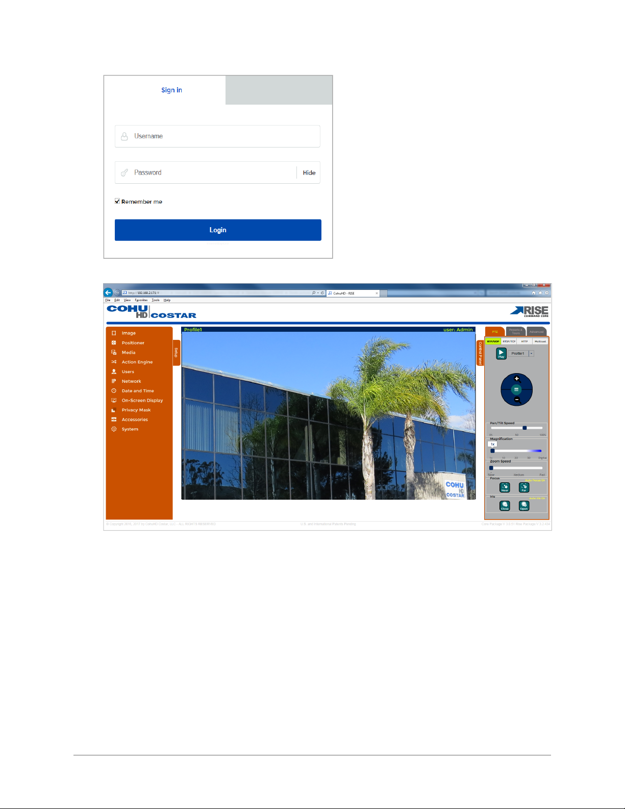
7. The Home page appears.
2.9 Users' Accounts
Four users’ accounts are defined in the web interface to allow differ ent levels of access. Those accounts are:
l Administrator
l Operator
l User
l Anonymous
- 14 -
3.0 Operation
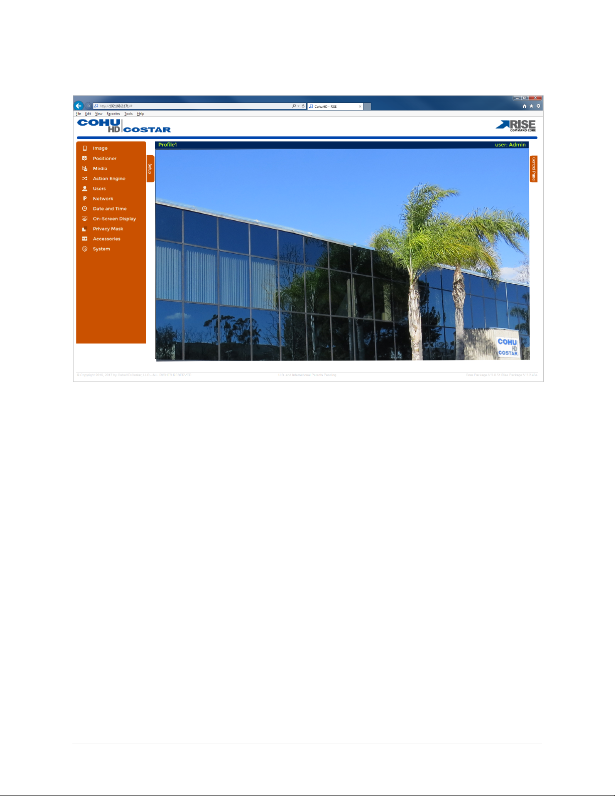
3.1 Home Page
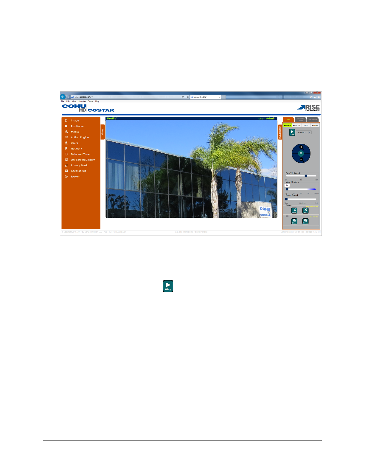
Use the Home page to view the video and control the camera.
View the Video
l Choose a profile from the drop-down list. Default is Profile 1. See "Profile Settings" on page 39
to configure a profile.
l Choose a transport mode from the top of the Control Panel. Default is RTP/UDP. See "PTZ
Control" on page 18 for more information.
l
Use Media Control Button: Play .
Move the Camera
To move the camera use the mouse or use the Positioner Control. See "PTZ Control" on page 18 for
more information on the Positioner Control.
Zoom the Camera
To zoom the camera use the mouse or use the PTZ Control tab. See "PTZ Control" on page 18 for more
information on the PTZ control.
Mouse Control
Use the mouse to control the camera azimuth, elevation and zoom in the video area.
l To move the camera:
Press the left mouse button and drag the mouse in the desired direction
l To zoom video in and out:
Scroll the mouse.
Setup Panel: Use this panel to configure the video.
- 15 -
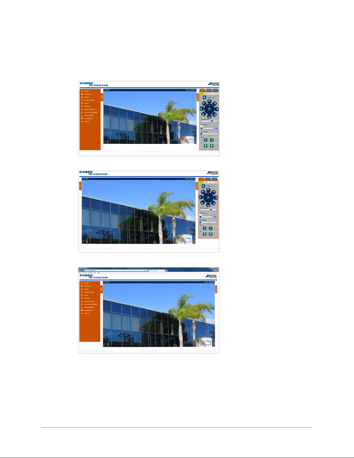
Control Panel: Use the panel to move the camera with the PTZ control and to have quick access to
frequently used controls.
Use the following screen mode options to view the video:
l To hide/show the browser information - click F11.
l To hide/show the Setup Panel - click the Setup tab.
l To hide/show the control panel - click the Control Panel tab.
- 16 -
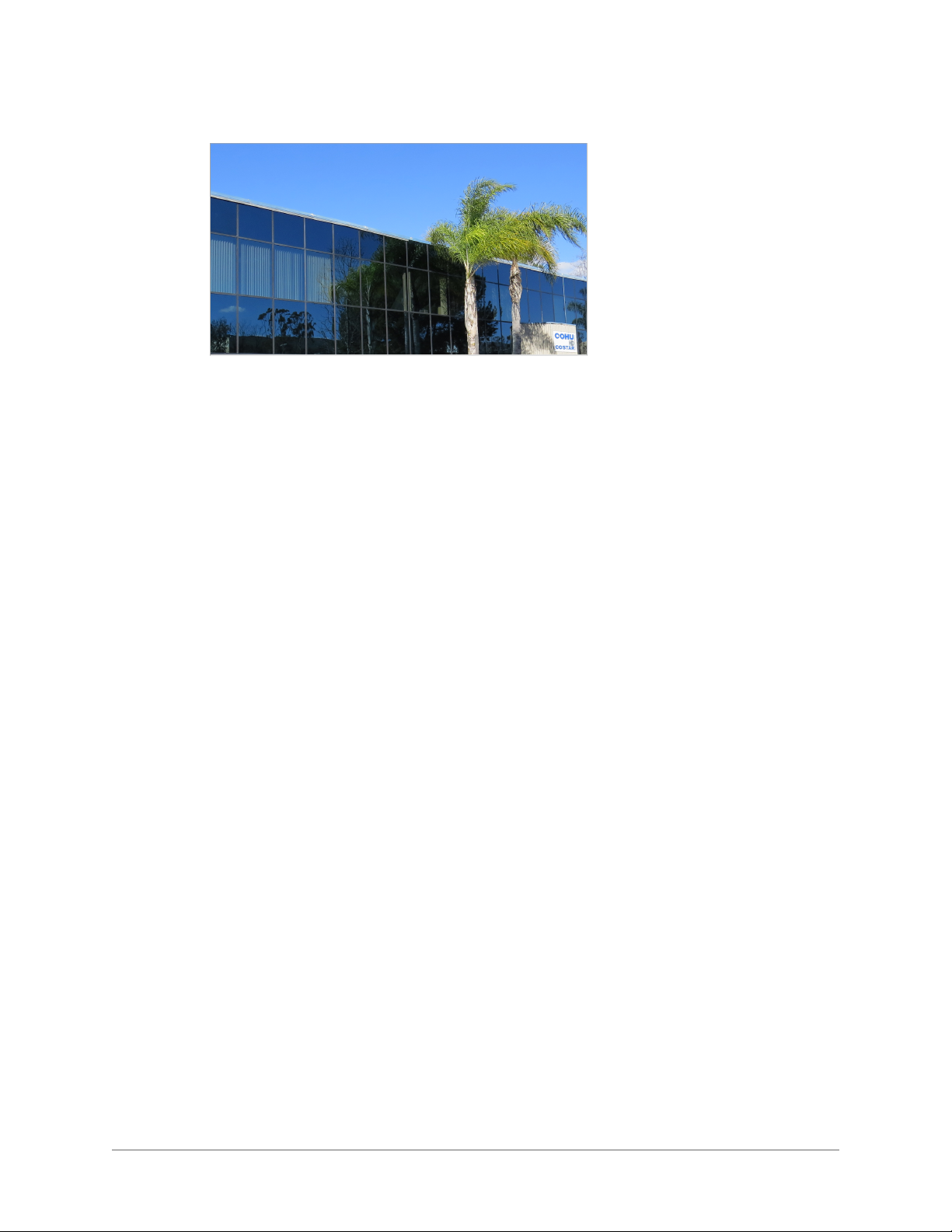
l To see full screen video - click the top blue bar with profile name and user name.
…
Click the Esc key to return to the previous screen.
- 17 -
3.2 Control Panel
The user must be logged in as Administrator, Operator or User to use the control panel.
Click on the Control Panel tab to show/hide the control panel.
The following tabs are available on the control panel:
l PTZ
l Presets and Tours
l Advanced
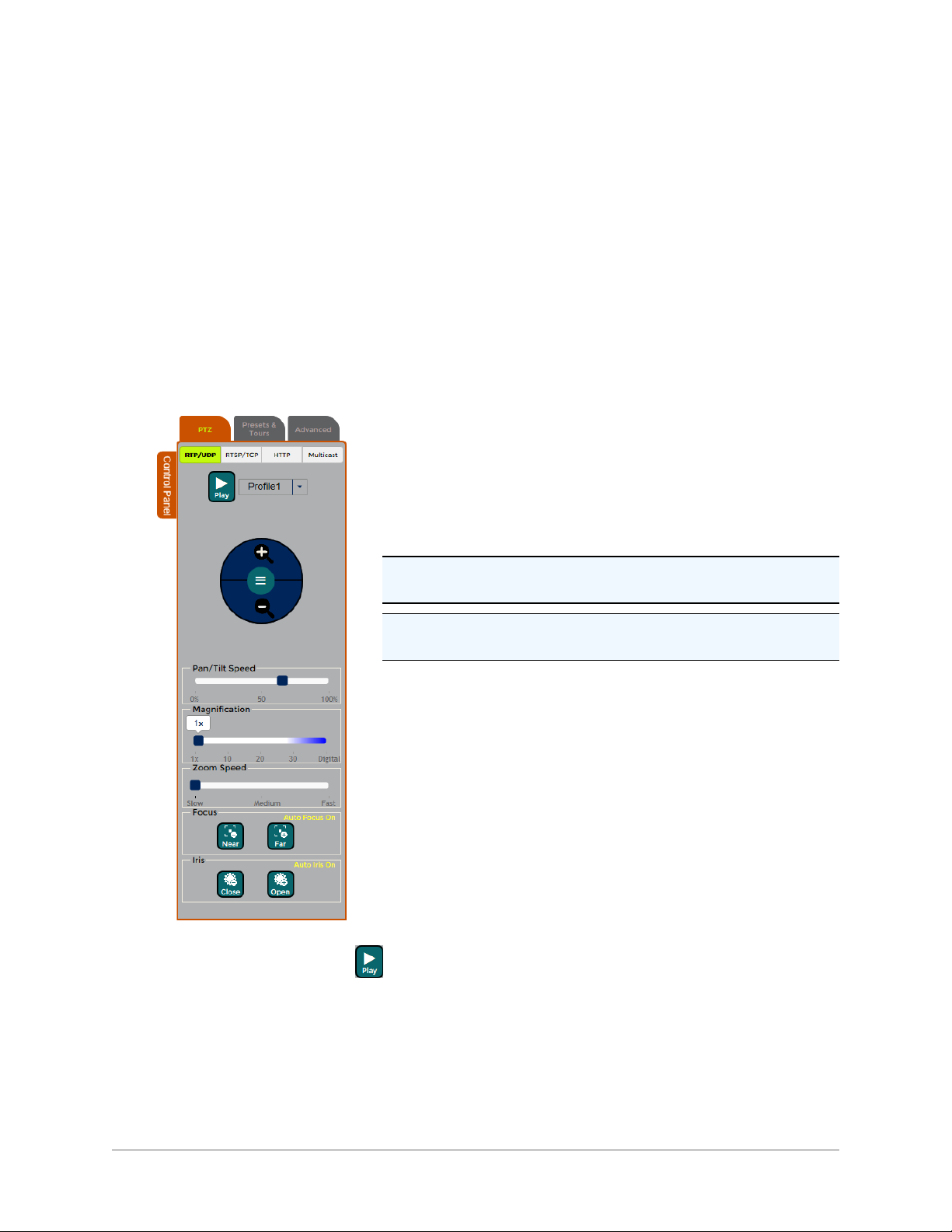
3.2.1 PTZ Control
The user must be logged in as Administrator, Operator or User to use the PTZ control.
Click the PTZ tab to bring the PTZ control panel to the screen.
The following buttons and controls are available on the PTZ tab:
Transport Modes
l RTP Unicast: Use RTP/UDP Unicast for video on demand
between the camera and a single receiver.
l RTSP/TCP: Use RTSP interleaved method to traverse firewalls.
l HTTP: Use HTTP tunneling method to traverse firewalls.
l RTP Multicast: Use RTP/UDP Multicast for a large simultaneous
number of viewers and for the most efficient usage of bandwidth.
Note 1: Multicast requires a custom configuration of most routers.
It is not possible to multicast over the Internet.
Note 2: Only 16 simultaneous connections are allowed for unicast
streaming.
Third Party Software
When using a third party software (e.g. VLC), enter the following
URLs:
l RTSP/RTP/UDP Unicast: rtsp://camera-ip-address/Stream0
(Stream0-Stream7)
l RTSP/RTP/TCP Unicast or RTSP Interleaved: rtsp://camera-ip-
address/Stream0 (Stream0-Stream7)
l RTSP/RTP/UDP Multicast: rtsp://camera-ip-address/mul-
ticast/Stream0 (Stream0-Stream7)
l RTP/UDP Multicast: http://camera-ip-address/sdp/Stream0.sdp
(Stream0-Stream7)
l HTTP/RTSP/RTP/TCP or HTTP Tunneling: http://camera-ip-
address/streaming/Stream 0 (Stream0-Stream7)
Media Control Button: Play
Profile: Choose a profile from the drop-down list. See "Profile Settings" on page 39 to configure a pro-
file.
- 18 -
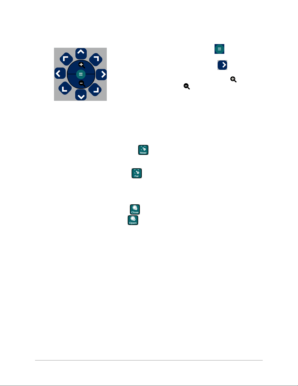
Positioner Control
l
Pan and Tilt (PT) Menu: Click the button to reveal the PT
direction arrows.
l
PT Arrow Buttons: Click one of the button to move the
camera in the desired direction.
l
Zoom In/Out Buttons: Press the Zoom In button to zoom in.
Press the Zoom Out button to zoom out; the camera will stop
at the maximum field of view.
Pan/Tilt Speed: Use the slide bar for changing the Pan/Tilt Speed.
Three speed levels are indicated by the number in percentage below
the slide bar.
Magnification: Use the slide bar for a continuous zoom. The zoom level is indicated by the number
below the slide bar.
Zoom Speed: Zoom speed is the speed at which the camera system will go from full wide zoom to the
optical zoom. Select the speed from the slide bar: Slow, Normal or Fast.
Focus Near: Press the Focus Near button to focus on a close object manually. The focus will con-
tinue to change until the button is released or until the focus reaches the limit of its travel. Auto focus
mode is off.
Focus Far: Press the Focus Far button to focus on a distant object manually. The focus will con-
tinue to change until the button is released or until the focus reaches the limit of its travel. Auto focus
mode is off.
Auto Focus: Click the Auto Focus line to bring the camera into Auto mode. In Auto mode, the focus
will be automatically changed based on the scene illumination. Manual focus modes are off.
Iris Close: Press the Iris Close button to manually close the iris. Auto iris modes are off.
Iris Open: Press the Iris Open button to manually open the iris. Auto iris mode is off.
Auto Iris: Click the Auto Iris line to bring the camera into Auto mode. In Auto mode, the iris will be auto-
matically changed based on the scene illumination. Manual iris modes are off.
- 19 -
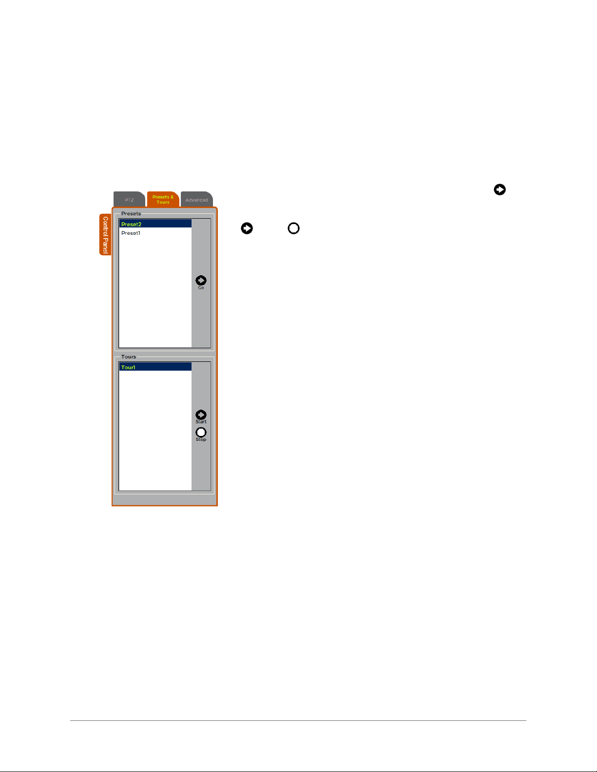
3.2.2 Presets and Tours Control
The user must be logged in as Administrator, Operator or User to use the Presets and Tours control.
Click the Presets and Tours tab to bring the Presets and Tours control panel to the screen. The Presets
and Tours panel allows users to have a quick access to already programmed presets and tours. See
"Preset Settings" on page 29 for more information on configuring presets. See " Tour Settings" on page
31 for more information on configuring tours.
The following buttons and controls are available on the Presets and Tours tab:
Presets: Choose a preset from the Presets list. Click the Go but-
ton to send the camera system to the chosen preset.
Tours: Choose the tour name from the Tours list and click the Start
or Stop button.
- 20 -
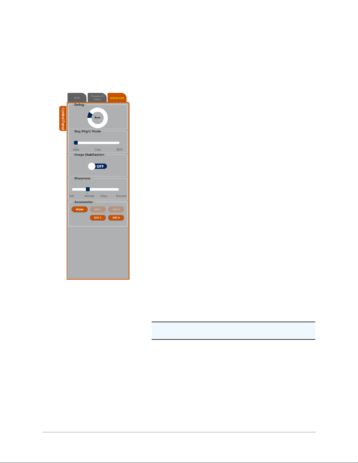
3.2.3 Advanced Control
The user must be logged in as Administrator, Operator or User to use the Advanced control.
Click the Advanced tab on the Control panel to bring the Advanced control to the screen.
The following buttons and controls are available on the Advanced tab:
Defog: Select one of the modes:
l Off
l Low
l Medium
l High
l Auto
See "Defog Settings" on page 26for more informationSee "Defog Set-
tings" on page 26
Day/Night Mode: Select one of the modes:
l Auto
l Color
l Black and White (B&W)
See "Exposure Settings" on page 24 for more information.
Image Stabilization: Select one of the modes:
l On
l Off
See " Advanced Settings" on page 27 for more information.
Sharpness: Select one of the modes:
l Soft
l Normal
l Sharp
l Sharpest
See " Advanced Settings" on page 27 for more information.
Accessories:
l Wiper: Click the button to start the wiper.
See "Accessory Settings" on page 89 for more information.
Note: The wiper button will be disabled if your camera does not
have a wiper.
l DIO: Click one of the buttons to activate a device, such as a
relay.
See " Digital IO Settings" on page 91 for more information.
- 21 -
3.3 Setup Panel
Click on the Setup tab to show/hide the Setup panel.
The Setup panel is used for configuring the camera. The following tabs are available from the camera configuration menu on the left side of the Setup tab:
l Image
a. Lens settings
b. Exposure Settings
c. Defog Settings
d. Advance Settings
l Positioner
a. Preset Settings
b. Tour Settings
c. Park Settings
d. Positioner Settings
l Media
a. Media Wizard
b. Media Utilization
c. Profile Settings
d. Stream Settings
e. Advanced Settings
l Action Engine
a. Action Engine Wizard
b. Email Server
c. FTP Server
d. Action Engine Configuration
e. Settings
- 22 -

l User
a. User Settings
l Network
a. Network Settings
b. Port Settings
c. Serial Settings
l Date and Time
a. Date and Time Settings
l On-Screen Setup
a. OSD Wizard
b. OSD Settings
c. OSD Banner Settings
d. OSD Sector Settings
e. OSD Logo Settings
l Privacy Mask
a. Pivacy Mask Wizard
b. Privacy Mask Add / Delete
c. Privacy Mask Settings
l Accessories
a. Accessory Settings
b. Digital IO Settings
l System
a. Information
b. Service
c. Support
d. System Messages
e. Licenses
- 23 -
3.3.1 Image
The user must be logged in as Administrator or Operator in order to make changes on the Image page.
Use the Image tab to configure lens and exposure settings and other image controls.
Click the Image tab to view the following panels:
l Lens Settings
l Exposure Setting
l Defog Settings
l Advance Settings
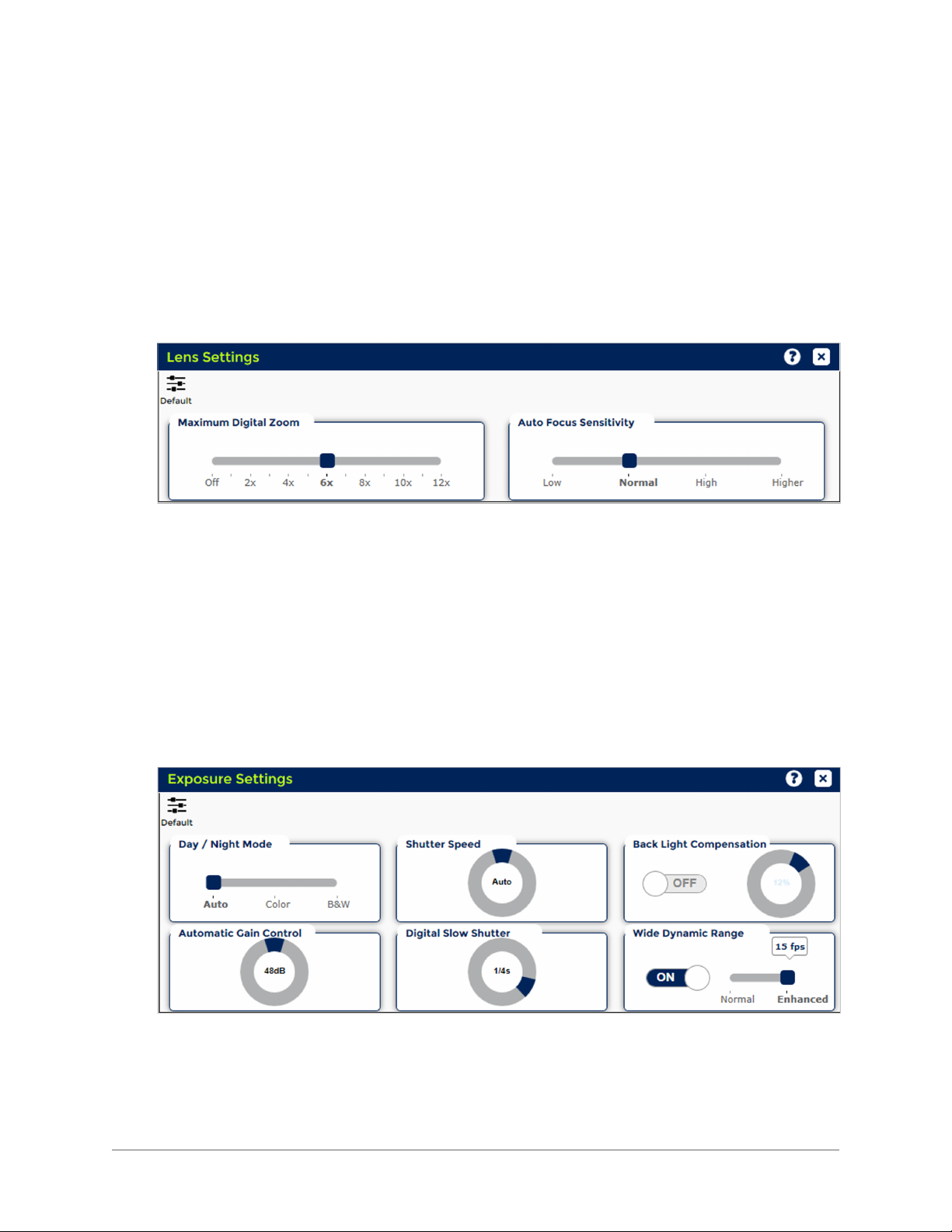
3.3.2 Lens Settings
Maximum Digital Zoom: Slide the bar to set the maximum digital zoom limit.
Auto Focus Sensitivity: The Auto Focus (AF) function automatically adjusts the focus position. User
can set up auto focus sensitivity in response to object change/movement.
AF sensitivity can be set to:
l Low: Slower auto focus reaction provides more stability when viewing scenes. Choose the
Low position for scenes with minimal changes.
l Normal: Auto focus reacts more conventionally to scene changes.
l High: Auto focus reacts faster and more often to scene changes.
l Higher: Choose the Higher position for scenes with rapid changes.
Default: Restores the factory default settings.
3.3.2.1 Exposure Settings
Day/Night Mode: The Day/Night mode determines whether the camera will produce a color image
with the IR cut filter in place or a black and white image with the IR cut filter removed.
Select one of the positions:
l Auto: The camera will automatically change between the Color and Black and White modes
based on the camera gain level. As the scene illumination decreases, the camera gain will
- 24 -

increase to a point where the camera will change to the Black and White mode, and the IR cut
filter will be removed from the light path. As the scene illumination increases, the camera gain
will decrease to a point where the camera will change to the Color mode, and the IR cut filter
will be inserted into the light path.
l Color: The camera will remain in the Color mode regardless of the camera gain level.
l Black and White (B/W): The camera will remain in the Black and White mode regardless of
the camera gain level.
Note 1: When changing from either Color or Black and White mode to the Auto mode there will be a
delay of approximately ten seconds before the automatic mode is engaged.
Note 2: The Auto Day/Night mode requires that the shutter speed also be in the Auto mode. If the
Shutter speed is not already in the Auto mode, selecting the Auto Day/Night mode will cause the
shutter to change into the Auto mode.
AGC (Automatic Gain Control) Limit: Increasing the AGC level will increase camera sensitivity
under low light conditions, but will also increase camera noise requiring more bandwidth when the
image is encoded. Decreasing the AGC level will lower camera sensitivity, but will also decrease camera noise, requiring less bandwidth when the image is encoded. Maximum AGC sets the maximum
gain level that the automatic gain will attain.
Shutter Speed: The shutter Speed determines the electronic shutter speed, or integration timing, of the
camera sensor.
Select the shutter speed:
l Auto: The shutter speed will automatically change based on the scene illumination.
l Manual: Selecting a shutter speed slower than 1/60 second (1/2 s through 1/30 s) will increase
the camera sensitivity, but will also increase image lag and blurring. Selecting a shutter speed
faster than 1/60 s will decrease camera sensitivity, but will improve the ability to
displaymoving objects.
Note: Selecting any Shutter speed other than Auto will force the camera to change from the
Day/Night Auto mode to either Color or Black and White mode. Selecting any Shutter speed other
than Auto locks the Shutter speed at that value.
Digital Slow Shutter (DSS) Limit: Select the value by changing the knob position. When the value is
set to 1/8 s or 1/15 s, the camera will automatically go into the long-term integration mode when the
light level decreases. Increasing the integration time of the sensor significantly increases the camera
sensitivity, but also significantly increases motion blur. Setting the value to Off prevents the camera
from entering the long-term integration mode, and is the recommended mode for most applications.
Important: When DSS is On, IS (Image Stabilization) is Off. See IS Section (Image > Advanced Settings > Image Stabilization).
Note: The lens iris and the camera exposure controls operate independently. Changes made to one
parameter may be automatically compensated for by the other. For example, in the Auto Iris mode,
manually changing the shutter speed may not appear to make a difference in the video output from
the camera because the iris is automatically compensating for the different shutter speed.
- 25 -
Backlight Compensation (BLC)
Select one of the modes:
l Off
l On
Important: When BLC is On, WDR is Off.
The BLC alters the automatic exposure control programming to prevent a bright background from
making dark parts of the image too dark.
A bright background can cause the automatic exposure control to make a dark area of the scene too
dark. When the dark area of the scene is more important than the bright area, enabling BLC will alter the
automatic exposure control by placing less emphasis on the bright area and more emphasis on the dark
areas.
BLC Level: Adjust BLC to a desired level.
Wide Dynamic Range (WDR):
Important: When WDR is On, BLC is Off.
The Wide Dynamic Range (WDR) balances the brightest and darkest sections of a scene to produce a
picture that is better balanced in lighting and provides more detail. When WDR is On, the frame rate is
reduced from the standard 30 frames per second (fps) to 15 fps. Also, when this setting is On, the iris
will not close completely even in manual mode.
Select one of the following choices when the WDR mode is On:
l Normal
l Enhanced
Default: Restores the factory default settings.
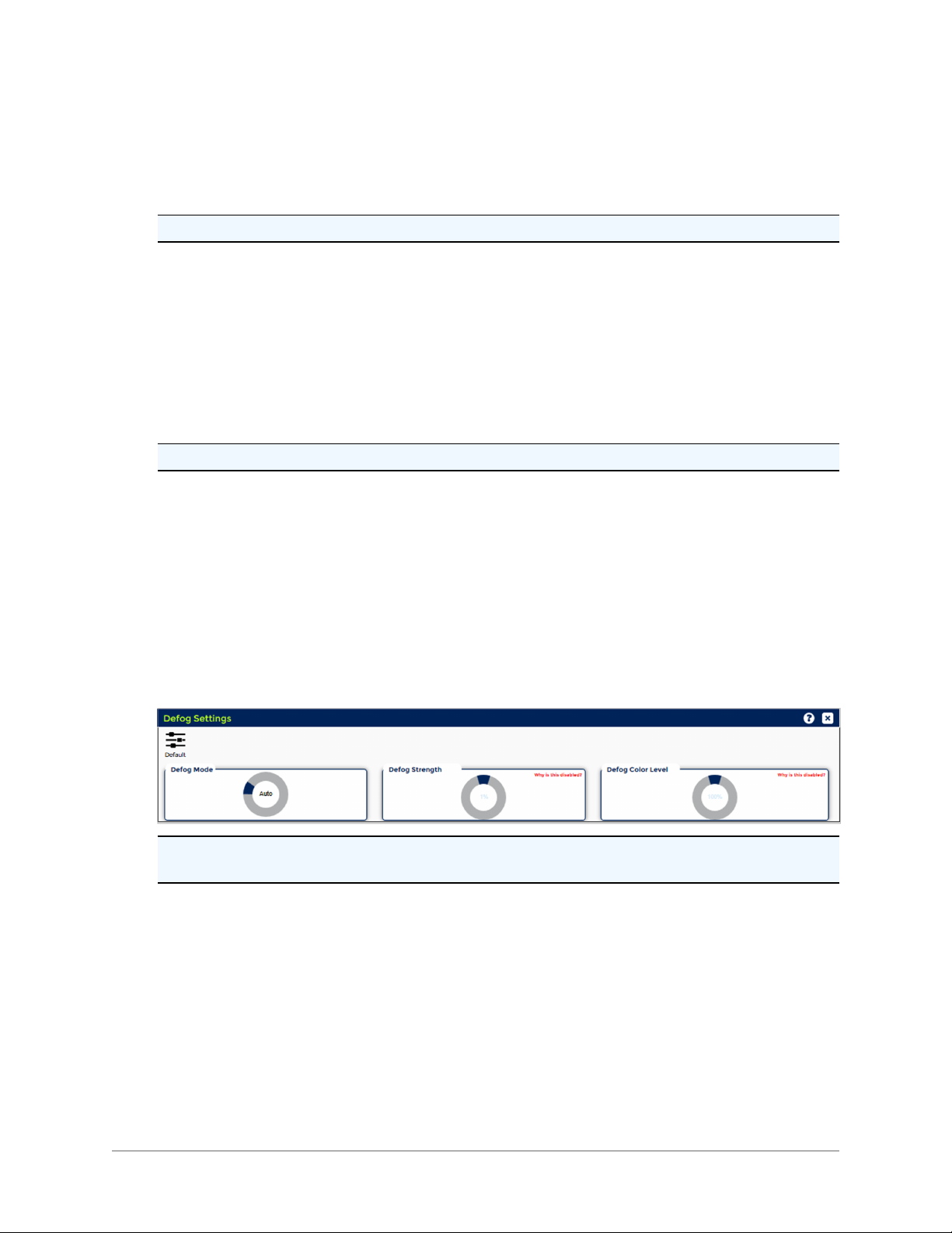
3.3.2.2 Defog Settings
Note: In order to use the Defog function, the Intensity Mode (Image > Advanced Settings > Intensity
Mode) must be set to Off.
Defog Mode: Select one of the modes:
l Off
l Low
l Medium
l High
l Auto
The Defog function helps to enhance image quality for viewing in smoky environments and bad
weather, such as rain, snow or fog.The defog control adjusts contrast, color, and sharpness.
l Auto: Select the Auto mode to automatically adjust the image in a foggy environment. In this
mode, the camera automatically recognizes the fog density and applies the necessary correction level. The Auto mode allows the defog function to be enabled full time. When no fog is
- 26 -
detected there is minimal compensation. The Auto mode has limitations under the following
conditions:
l Image is not in focus
l Images are too dark or too bright because of the iris control related function
l BLC is turned On
l WDR is turned On
l The scene has low contrast
l The scene has high contrast
l Manual: Select one of three manual levels of enhancement, depending on fog thickness:
l Low for light fog density
l Medium for medium fog density
l High for heavy fog density.
Defog Strength: Change the knob position to increase the defog level in poor visibility.
Note: The Defog Strength level can be changed when Defog Mode is set to Auto.
Defog Color Level: In the Manual Defog Mode, change the knob position to change the image color
level.
Note: Defog Color Level cannot be changed when Defog Mode is set to Off.
Default: Restores the factory default settings.
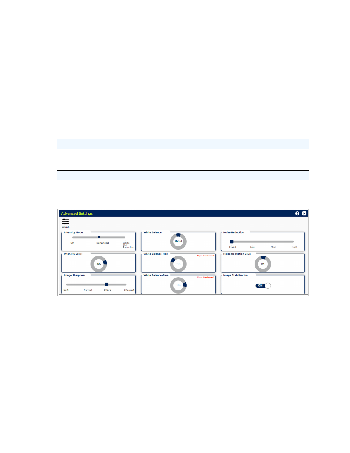
3.3.2.3 Advanced Settings
Intensity Mode: Select one of the modes:
l Off
l Enhanced: Use this function to improve images in dark areas such as unlit areas or shadows.
The enhanced intensity function brightens dark areas while not affecting light areas.
l Whiteout Reduction: The Whiteout Reduction is a function that reduces a whiteout area of
the image. Scenes with strong reflection may cause the image to white out or lose dark details.
For example, when very bright sources of light, such as vehicle headlights, are captured,
neighboring surfaces, such as license plates, may result in reflections leading to white out.
Intensity Level:Change the knob position to improve image quality.
Image Sharpness: The Image Sharpness function detects the sharpness of the edge of an object.
Select one of the modes:
l Soft
l Normal
- 27 -

l Sharp
l Sharpest
White Balance: Select one of the modes:
l Manual: The Manual white balance prevents the automatic white balance compensation and
allows the operator to manually change the red and blue levels for a specific light condition.
l Auto (Normal, Sodium, Mercury): The Auto white balance will automatically compensate for
changing light conditions to maintain correct color reproduction, especially during the transition
from day to night or from night to day. Choose Normal, Sodium or Mercury.
White Balance - Red: Available in the Manual White Balance mode. Change the knob position to
adjust the red color level.
White Balance - Blue: Available in the Manual White Balance mode. Change the knob position to
adjust the blue color level.
Noise Reduction (NR) Mode: Use the NR to decrease the noise by frame correction.
Select one of the modes:
l Fixed
l Low (Auto Low Lag)
l Medium (Auto Medium Lag)
l High (Auto High Lag)
Noise Reduction Level: Change the knob position to adjust the NR level.
Note: Noise Reduction Level can be changed when Noise Reduction is set to the Fixed mode.
Image Stabilization (IS): Use the IS function to stabilize the image if the camera is subject to vibration.
Select one of the modes:
l On
l Off
When the IS function is On, the DSS (Digital Slow Shutter speed) function will be disabled. IS must be
Off to allow integration (DSS).
The relationship between IS and WDR:
l IS and WDR (Wide Dynamic Range) cannot function at the same time. IS has priority over
WDR.
l WDR will be disabled when IS is turned On during WDR operation.
l WDR will not be automatically reinstated when IS is turned Off. Turn WDR back On manually.
Default: Restores the factory default settings.
- 28 -
3.3.3 Positioner
The user must be logged in as Administrator or Operator in order to make changes on the Positioner
page.
Use the Positioner tab to configure presets, tours and other positioner controls.
Click the Positioner tab to view the following panels:
l Presets Settings
l Tours Settings
l Park Settings
l Positioner Settings
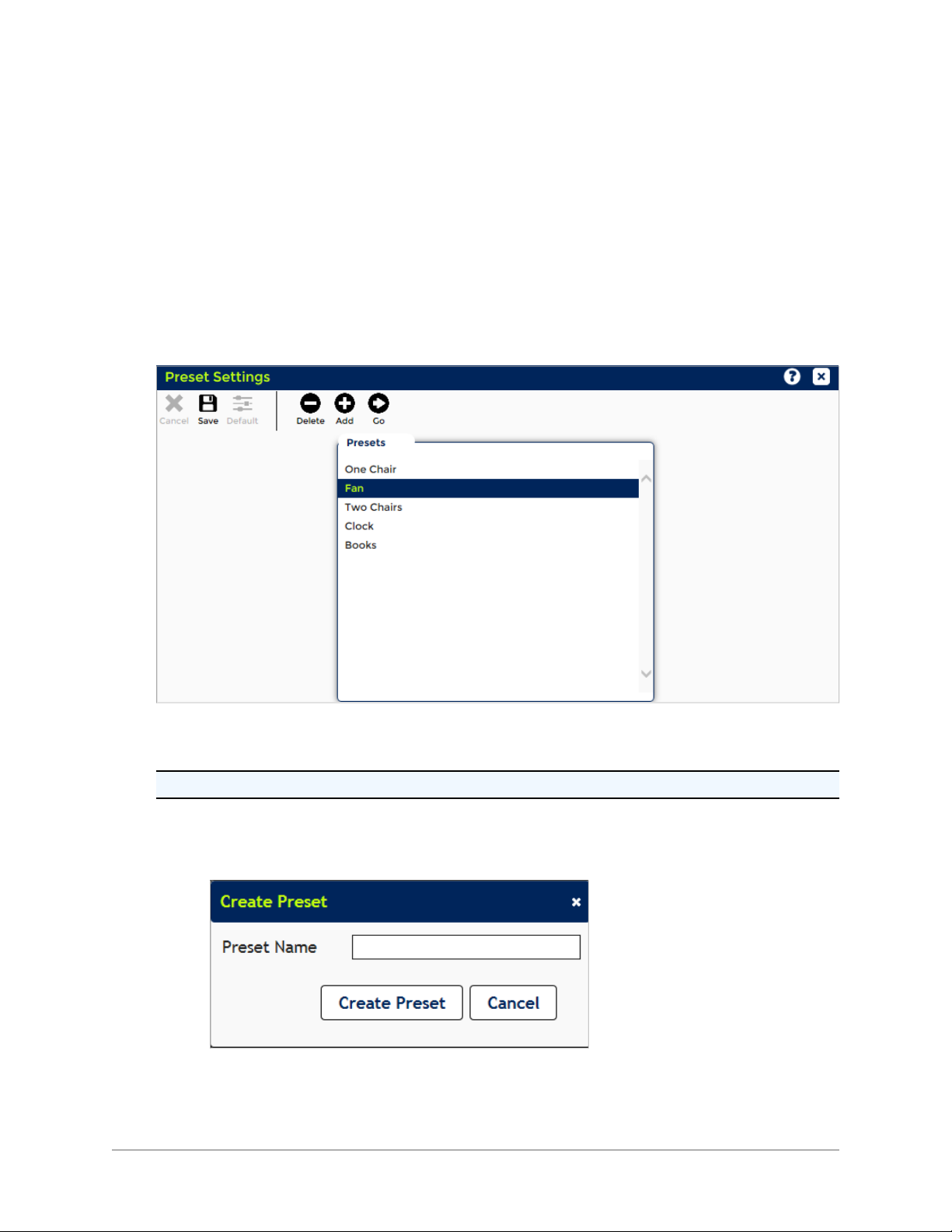
3.3.3.1 Preset Settings
Presets are predefined pan, tilt, zoom and focus camera views that are stored in the camera.
The camera system supports 256 presets.
Note: When received, camera systems do not have any established presets.
To create a new preset:
1. Move the camera to the desired position.
2. Click the Add button. A new window will appear.
3. Type a name.
4. Click the Create Preset button. A new Preset name will be added to the Presets table, the Pre-
- 29 -

sets list in the PTZ control, and in the Available Presets table in the Tour Settings panel.
5. Click the Cancel button to cancel the create preset operation.
To delete a preset:
1. Select a preset name in the Presets table.
2. Click the Delete button to delete a preset.
To change a preset location but keep the same preset name:
1. Select a preset name in the Presets table.
2. Move the camera to the desired position.
3. Click the Save button. A new window will appear.
4. Click the Save Preset button to save this preset.
5. Click the Cancel button to cancel the create preset operation.
To go to a desired preset:
l Select a preset name in the Presets table.
l Click the Go button.
Cancel: Disabled on this screen.
Save: Disabled on this screen.
Default: Disabled on this screen.
- 30 -
 Loading...