

CohuHD Costar 3430HD Installation And Operation Manual
3430HD
IP HD Fixed Camera
Installation and Operation
Manual 6x-1118A
2016 CohuHD Costar

Contents
PART ONE – QUICK USER QUIDE ................................................................................................................................................. 3
IMPORTANT INFORMATION ........................................................................................................................................................ 3
OVERVIEW .................................................................................................................................................................................. 5
FEATURES ........................................................................................................................................................................................... 5
CAMERA DIAGRAMS ................................................................................................................................................................... 6
PIG-TAIL CABLE ........................................................................................................................................................................... 6
INSTALLING YOUR CAMERA ........................................................................................................................................................ 8
CHECK CAMERA COMPONENTS AND INSTALLATION CONDITIONS ................................................................................................................... 8
MOUNTING THE CAMERA .................................................................................................................................................................... 10
STARTING THE CAMERA ............................................................................................................................................................ 11
SETTING CAMERA OVER THE LAN ......................................................................................................................................................... 11
ACCESSING YOUR CAMERA ................................................................................................................................................................... 11
INSTALLING THE ACTIVEX ..................................................................................................................................................................... 12
DIMENSIONS ............................................................................................................................................................................. 13
PART TWO - NETWORK CAMERA USER MANUAL ...................................................................................................................... 14
NETWORK CONNECTION ........................................................................................................................................................... 14
LOGIN .............................................................................................................................................................................................. 14
LOGGING INTO THE WEB INTERFACE ...................................................................................................................................................... 16
INTRODUCTION TO THE WEB INTERFACE ................................................................................................................................................. 17
CONFIGURING PARAMETERS .................................................................................................................................................... 19
LOCAL PARAMETERS ........................................................................................................................................................................... 19
NETWORK CONFIGURATION ................................................................................................................................................................. 20
IMAGE CONFIGURATION ...................................................................................................................................................................... 24
MEDIA STREAM CONFIGURATION .......................................................................................................................................................... 36
(FUTURE) ALARM CONFIGURATION ..................................................................................................................................................... 37
(FUTURE) MEMORY CARD STORAGE .................................................................................................................................................... 44
SYSTEM MAINTENANCE ....................................................................................................................................................................... 47
LIVE VIEW ................................................................................................................................................................................. 51
LIVE VIEW TOOLBAR ........................................................................................................................................................................... 51
VIEWING CERTAIN AREA OF IMAGES ...................................................................................................................................................... 52
(FUTURE) VIDEO PLAYBACK AND DOWNLOAD WITH EDGE STORAGE ....................................................................................... 53
VIDEO PLAYBACK................................................................................................................................................................................ 53
DOWNLOAD ...................................................................................................................................................................................... 53
APPENDIX A GLOSSARY ............................................................................................................................................................. 56
APPENDIX B FAQ ....................................................................................................................................................................... 58
2

Operating Instructions
Symbol
Description
WARNING
Contains important safety instructions and indicates situations that may cause bodily injury.
CAUTION!
User must be careful and improper operations may cause damage or malfunction of product.
NOTE!
Indicates useful or supplemental information about the use of product.
Before operating the unit, please read this manual thoroughly and retain it for future reference.
Thank you for purchasing our product. If there are any questions, please contact the authorized dealer.
PART ONE – QUICK USER QUIDE
IMPORTANT INFORMATION
Legal Notice
Attention:
To ensure account security, please change the password after your first login. You are recommended to set a strong
password (no less than eight characters).
The contents of this document are subject to change without prior notice. Updates will be added to the new version of this
manual. We will readily improve or update the products or procedures described in the manual.
No statement, information, or recommendation in this manual shall constitute formal guarantee of any kind, expressed or
implied. We shall not be held responsible for any technical or typographical errors in this manual.
The product appearance shown in this manual is for reference only and may be different from the actual appearance of your
device.
This manual is a guide for multiple product models and so it is not intended for any specific product.
Due to uncertainties such as physical environment, discrepancy may exist between the actual values and reference values
provided in this manual.
Use of this document and the subsequent results shall be entirely on the user’s own responsibility.
Symbols
Safety Information
WARNING!
Installation and removal of the unit and its accessories must be carried out by qualified personnel. You must read all of
the Safety Instructions supplied with your equipment before installation and operation.
Warnings:
If the product does not work properly, please contact your dealer. Never attempt to disassemble the camera yourself.
(We will not assume any responsibility for problems caused by unauthorized repair or maintenance.)
This installation should be made by a qualified service person and should conform to all the local codes.
When shipping, the camera should be packed in its original packaging.
Make sure the power supply voltage is correct before using the camera.
Do not drop the camera or subject it to physical shock.
Do not touch sensor modules with fingers. If cleaning is necessary, use a clean cloth with a bit of ethanol and wipe it
gently. If the camera will not be used for an extended period of time, put on the lens cap to protect the sensor from
3

dirt.
Do not aim the camera lens at the strong light such as sun or incandescent lamp. The strong light can cause fatal
damage to the camera.
Maintenance Precautions:
If there is dust on the front glass surface, remove the dust gently using an oil-free brush or a rubber dust blowing
ball.
If there is grease or a dust stain on the front glass surface, clean the glass surface gently from the center outward
using anti-static gloves or an oil-free cloth. If the grease or the stain still cannot be removed, use anti-static
gloves or an oil-free cloth dipped with detergent and clean the glass surface gently until it is removed.
Do not use organic solvents, such as benzene or ethanol when cleaning the front glass surface.
Regulatory Compliance
FCC Part 15
This equipment has been tested and found to comply with the limits for digital device, pursuant to part 15 of the FCC
Rules. These limits are designed to provide reasonable protection against harmful interference when the equipment is
operated in a commercial environment. This equipment generates, uses, and can radiate radio frequency energy and, if
not installed and used in accordance with the instruction manual, may cause harmful interference to radio
communications. Operation of this equipment in a residential area is likely to cause harmful interference in which case
the user will be required to correct the interference at his own expense.
This product complies with Part 15 of the FCC Rules. Operation is subject to the following two conditions:
This device may not cause harmful interference.
This device must accept any interference received, including interference that may cause undesired operation.
LVD/EMC Directive
This product complies with the European Low Voltage Directive 2006/95/EC and EMC Directive
2004/108/EC.
WEEE Directive–2002/96/EC
The product this manual refers to is covered by the Waste Electrical & Electronic Equipment (WEEE)
Directive and must be disposed of in a responsible manner.
4

Overview
This user guide is suitable for the following models:
3432-1000
Features
Resolution: 1080P
Optical Zoom: 30X
Day and night automatic conversion function (ICR)
Supports 3D noise reduction
Video Output: IP
H.264 encoding, higher compression efficiency
3 data stream function will satisfy various bandwidth, frame rates and storage requirements in real time
Outdoor Environmental Rating: IP67
Input Power: PoE or 12 Vdc
Supports ONVIF Profile S
5

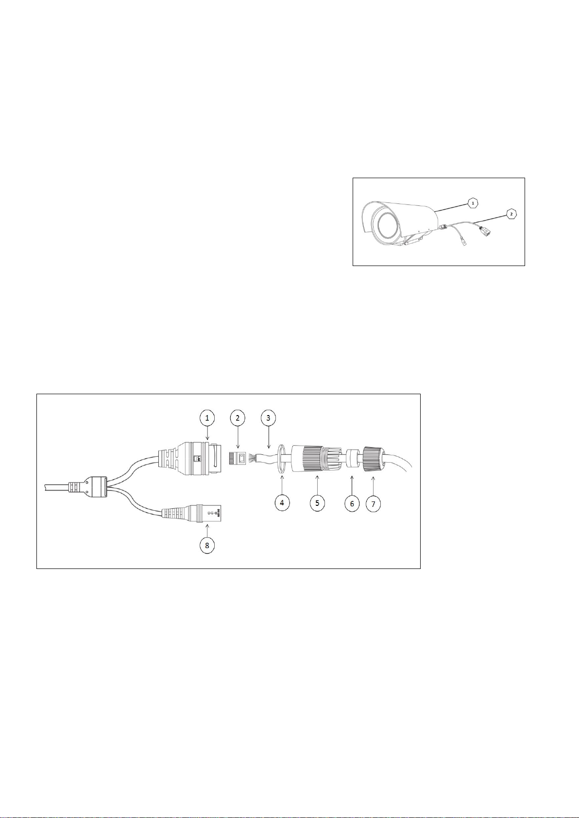
Camera Diagrams
①
Network Port
②
Power Port
③
Waterproof Head
Camera
1. Sunshield Cover
2. Camera Faceplate
3. Camera Enclosure
Camera Pig-Tail Cable
6
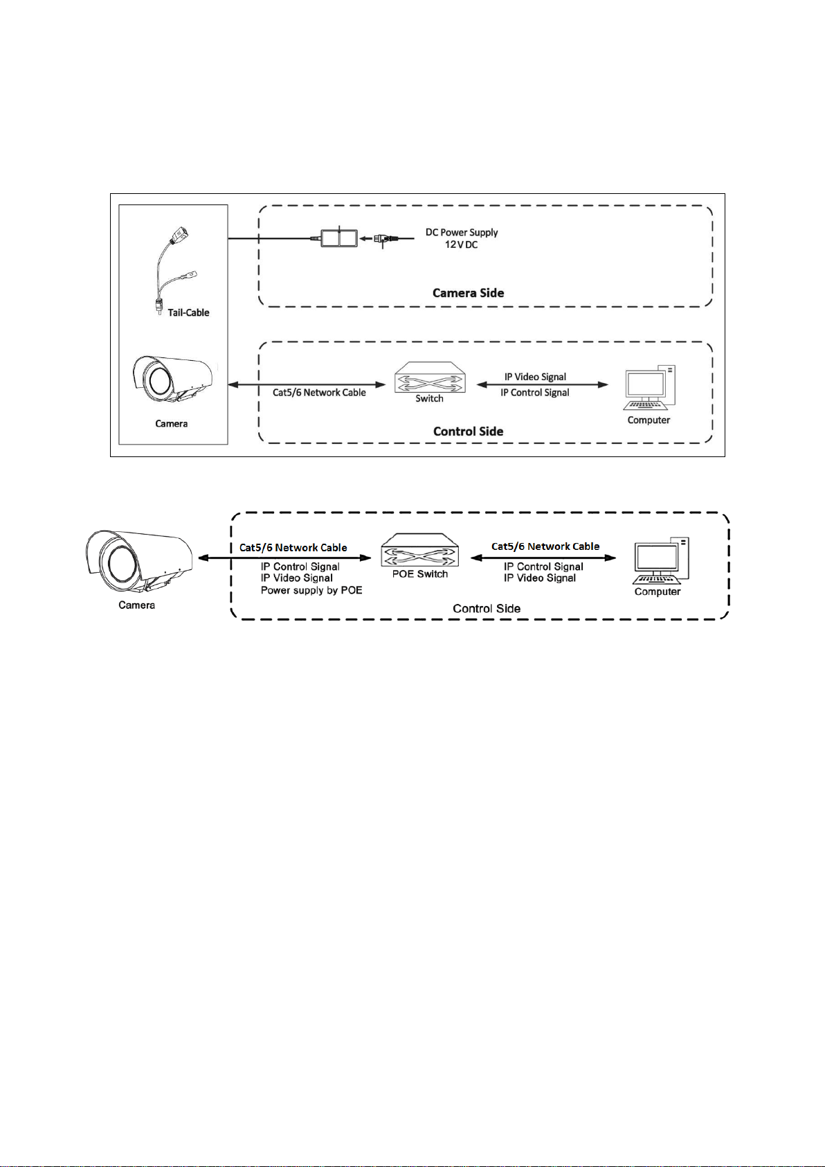
Cable Connection
Mode 1: Power by DC Adapter
Mode 2: Power by POE
7
Installing Your Camera
①
Network Port
②
Crystal Head
③
Network Cable
④
Silicone Ring
⑤
Paw
⑥
Silica Gel Pad
⑦
Hat
⑧
Power Port
The following diagrams are for your reference only. See the actual product to mount your camera.
Check Camera Components and Installation Conditions
Before mounting your camera, check the device model number and included contents against the packing list to ensure
components are complete.
Camera Structure
1. Camera Body
2. Pig-Tail Cable
3. Waterproof Connector Kit
Important
Verify the bearing capacity of the mounted position
Verify that the mounted position meets the bearing requirements. Otherwise, you are advised to reinforce the
mounted position for the device weight. For more information, see the product datasheet.
Verify lightning protection and grounding requirements
Ground the terminal properly.
Network Cable Installation
1. Insert the ③Network cable through the waterproof head kit (④/⑤/⑥/⑦).
2. Insert the Crystal head.
3. Insert the crystal into the network port.
4. Tighten the head kits (④/⑤/⑥/⑦).
Cable Requirements
Network Cable
10/100 Mbps Ethernet CAT 5/5E/6 UTP cables are applicable to the ANSI/EIA/TIA-568A/B and ISO/D.
Eight wires in the network cable need to be inserted in parallel into the top of the cable connector. The cable connector
needs to be crimped in position. When the cable connector is in position, ensure that the metal pieces of the cable
connector are parallel to each other and the clamp of the cable connector is intact.
8

Power Cable
Core Diameter (Unit: mm)
Distance (Unit: m)
Power (Unit: W)
0.80
1.00
1.25
2.00
30
28
45
72
183
40
21
34
54
137
50
17
27
43
110
60 - 22
36
91
70 - 19
31
78
80 - -
27
68
90 - -
24
61
100 - -
21
55
Data listed in Table 2-1 is applicable to copper cables that use 12 Vdc power supply. The item Core Diameter indicates
the conductor diameter.
Power Loss on the Cable for Different Lengths and Different Core Diameters
Power Connector: Phoenix Connector Description
1. The anode and the cathode are not distinguished for phoenix connectors of red and black cables.
2. GND: yellow-green color.
Note: GND is used to ground the camera. Ensure that GND is connected to a reliable grounding point.
NOTE!
Disconnect the power from the camera before mounting.
Accessories such as the wall mount bracket and the pendant mount bracket may be necessary during mounting. For
their model, refer to the accessory list recommended by your dealer.
The wall bearing capacity and the bracket length must meet all onsite mounting requirements. You will need to select a
mount type based the actual environment.
POE Specifications
Standard: 802.3af
Electrical equipment power: less than 15W
Input voltage range: 44V-58V
Requirements: Cat5 or higher cable
9
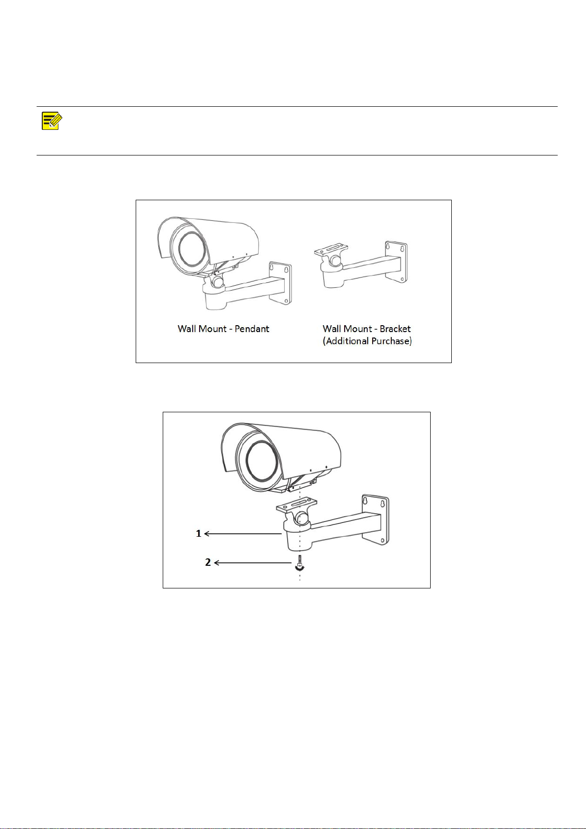
Mounting the Camera
NOTE!
Tighten all the screws to hold the camera securely.
Wall Mount
1. Install the wall mount bracket.
2. Install the screw to lock the camera tight.
10

Starting the Camera
Item
Requirements
Operating
System
Microsoft Windows 8/Windows 7/Windows XP (32-bit or
64-bit). Microsoft Windows 7 (32-bit) is recommended.
CPU
2.0 GHz or higher, dual-core. Intel i3 CPU or higher are
recommended.
Memory
At least 1 GB. 2 GB (or higher) is recommended.
Graphic
Card
At least 128 MB display memory. Mainstream discrete
graphics with more than 1 GB display memory are
recommended. The hardware should support DirectX9.0c.
Note: Make sure that the latest driver is installed on graphic
card.
Sound
Card
Essential.
Note: The intercom and voice broadcast require the latest
driver on sound card.
Network
Card
Gigabit
Ethernet
network cards
(or
higher)
are
recommended.
After you have mounted the camera properly, connect the camera to power.
Each time the camera is powered on, it will perform a self-test to check internal functions. After the self-test is complete,
you will be able to operate the camera.
NOTE!
The self-test process starts after the camera is powered up. Please wait patiently.
Operation of Camera over a LAN
To view and configure your camera via the local area network (LAN), you need to know the cameras IP address. The
factory default setting is:
192.168.2.150
255.255.255.0
Login Credentials: User = admin | Password = admin
NOTE!
The default IP address is “192.168.2.150”. The default username is “admin”, and the default password is “admin”
or “admin”.
To access your camera from a different subnet, set the gateway for your camera after you log in.
Accessing Your Camera
You can manage and control the camera through the web interface from a PC.
System Requirements for Your PC
11
Accessing Your Camera
Before you begin, please ensure:
1. The self-test is completed.
2. Your camera is operating properly and connected to the network.
3. The PC client you are using is installed with Internet Explorer 8.0 or higher.
Follow the next steps:
1. Open Internet Explorer on your PC.
2. In the address bar, input the IP address of your camera (Default IP is 192.168.2.150) and then press Enter to
open the login page.
3. Enter the username (default is “admin”) and password (default is “admin”) and then click Login.
NOTE!
Install the ActiveX on your first login. For detailed steps, see Installing the ActiveX. When the installation of the ActiveX is
completed, open IE to log in.
Installing the ActiveX
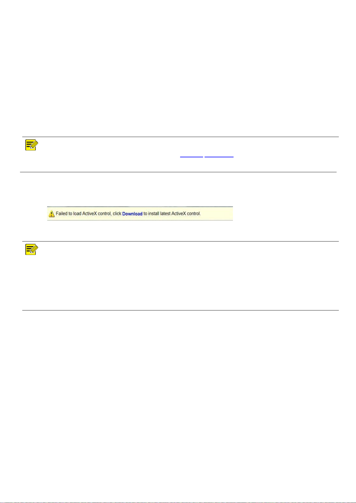
The following message will show in IE browser on the first login. Click Download to install Active X.
Click Run. You may also click Save to download the file to your computer first.
Close the browser and follow the steps to complete the installation.
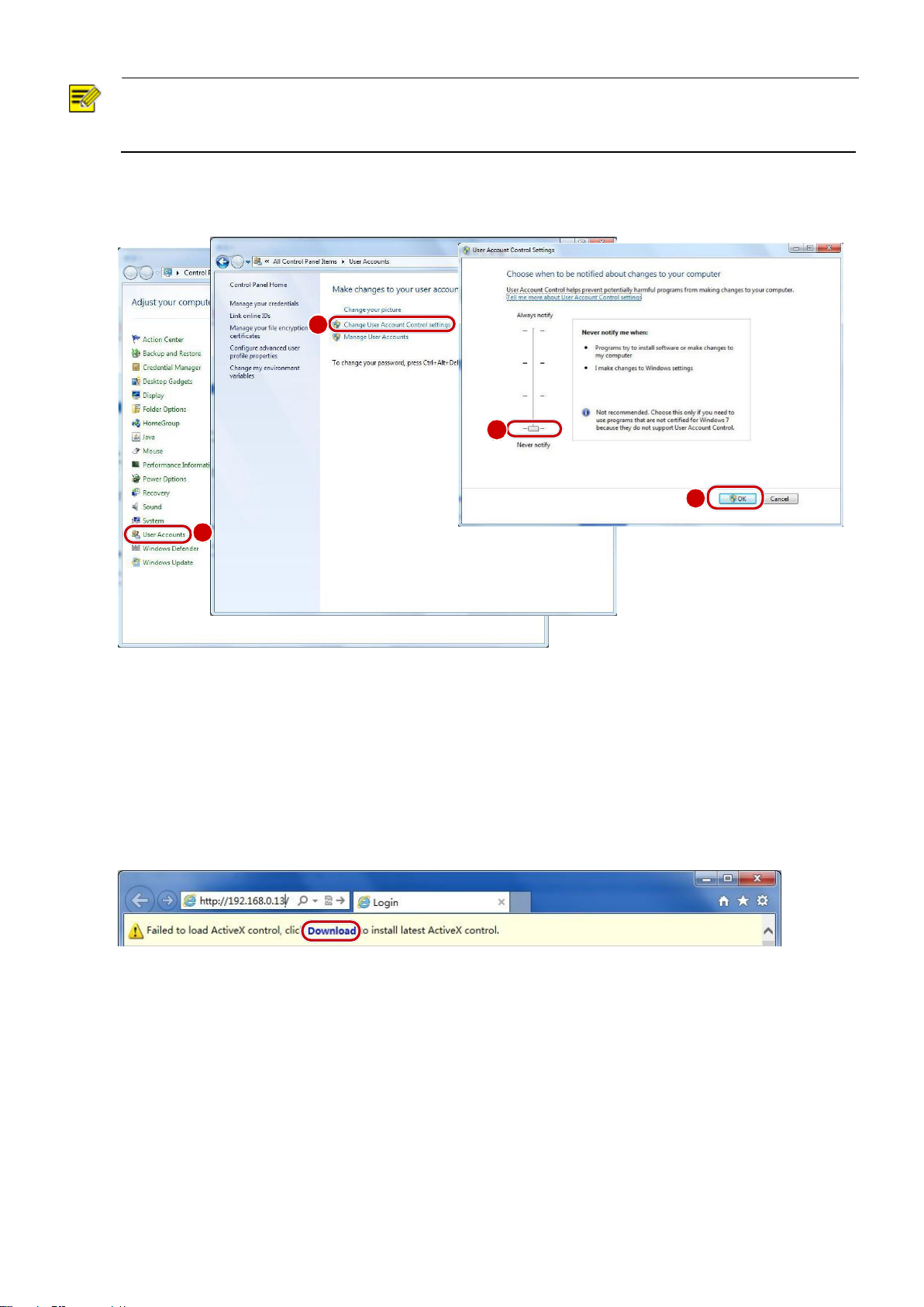
NOTE!
For your first login with Windows 7, if the system does not prompt you to install ActiveX, follow these steps to turn off UAC:
Click the Start button; then click Control Panel. In the search box, type UAC; then click Change User Account Control Settings.
Move the slider to the Never Notify position; then click OK. After UAC is turned off, log in again.
If the installation fails, open Internet Option in IE before login. Click the Security tab, click Trusted sites, and then click Sites to
add the website. If you use Windows 7, you need to save the setup.exe to your PC first; then right-click the file, select Run as
administrator, and then install it according to instructions.
12

Dimensions
Unit: mm
.
13
Network cable
Network cable
Network cable
PART TWO - NETWORK CAMERA USER MANUAL
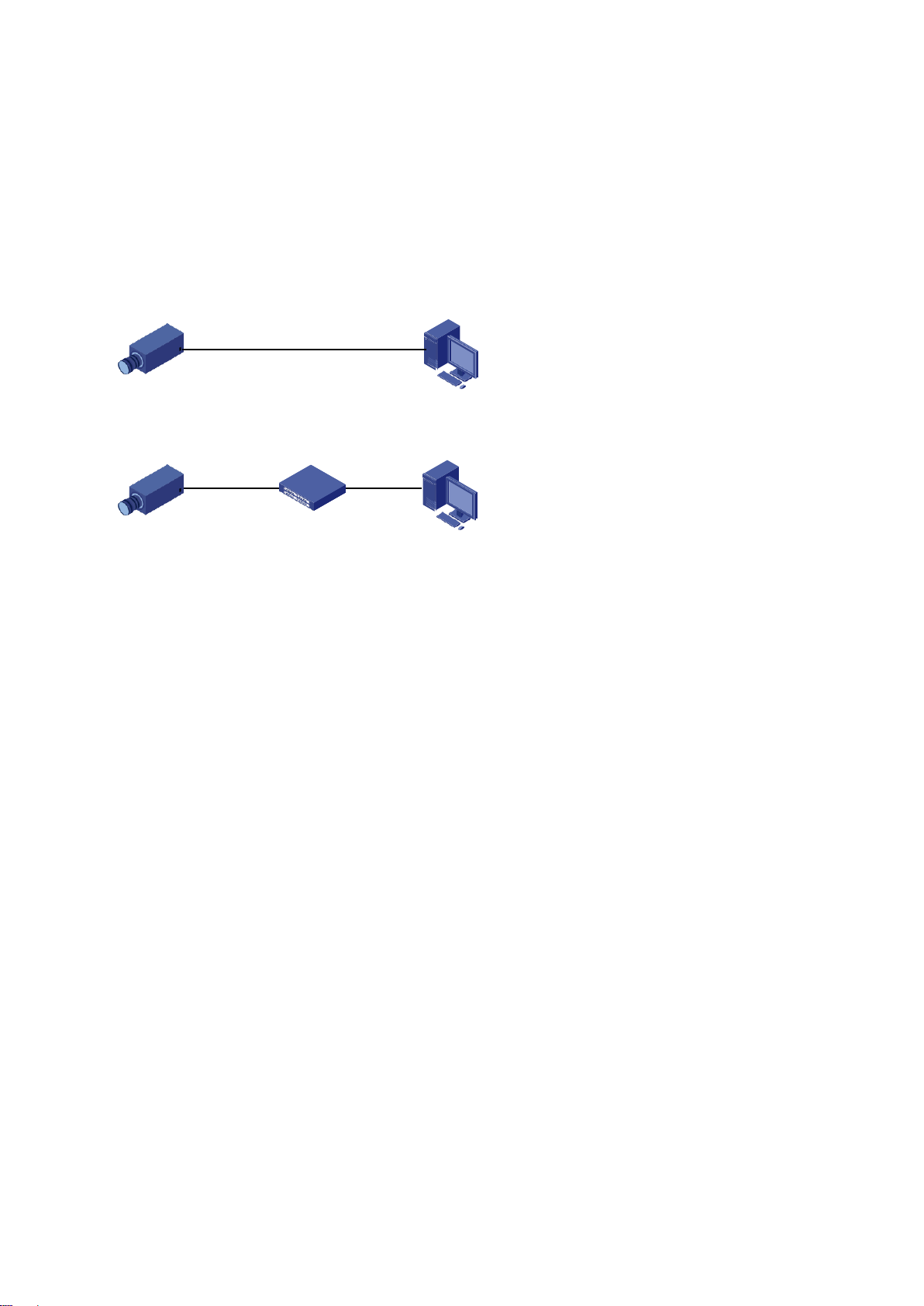
Network Connection
Before accessing a network camera (also known as IP Camera or IPC) from a PC, you need to connect the
network camera to the PC directly with a network cable or via a switch or router.
IPC
Use a Shielded Twisted Pair (STP) cable to connect the network interfaces of the network camera and the PC.
IPC
Use Shielded Twisted Pair (STP) cables to connect the network interfaces of the camera and the switch or router.
Login
Preparation
After you have completed the installation in accordance with the quick guide, connect the camera to power to
start it. After the camera is started, you can access the camera from a PC client installed with a web browser.
Internet Explorer (IE) is a recommended web browser. The following takes IE on a Microsoft Windows 7.0
operating system as an example.
Check before login
PC
Switch or Router PC
The camera is operating correctly.
The network connection between the PC and the camera is normal.
The PC is installed with Internet Explorer 8.0 or higher.
The resolution is set to 1920 x 1080
14

Add the IP address as a trusted site
http://192.168.2.150
5
Clear the check box
6 3 4
7 1
2
15
NOTE!
2 3 4 1
The IP address 192.168.2.150 in this example is the default IP address. Please replace it with the actual address
of your camera if it has been changed.
(Optional) Modify user access control settings
Before you access the camera, follow the steps to set User Account Control Settings to Never notify.
Logging Into the Web Interface
The default static IP address of the camera is 192.168.2.150, and the default subnet mask is 255.255.255.0.
DHCP is turned on by default. If a DHCP server is used in the network, the IP address of your camera may
be assigned dynamically, and you need to use the correct IP address to log in.
The following takes IE as an example to describe the login procedure.
1. Browse to the login page by entering the correct IP address of your camera in the address bar.
2. If you log in for the first time, follow system prompts and install the ActiveX. You need to close your
browser to complete the installation.
16
NOTE!
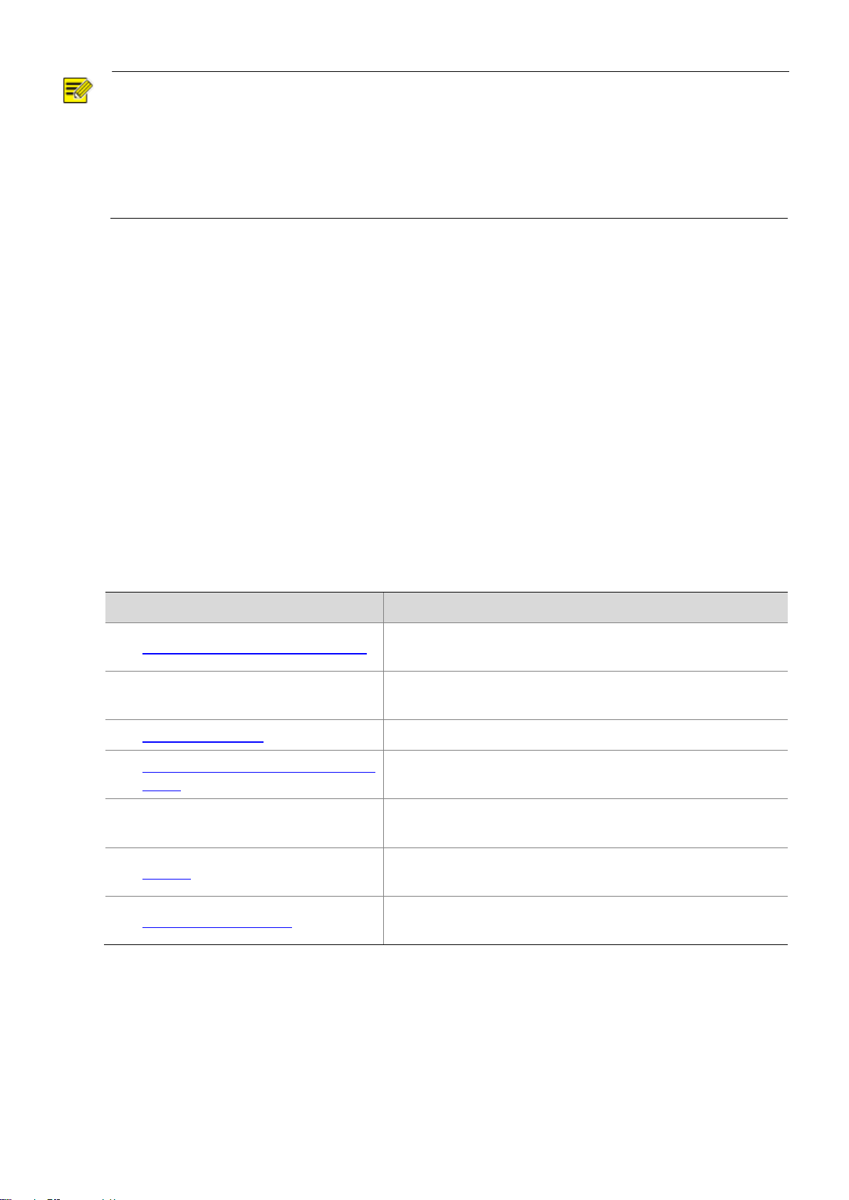
Item
Description
1. Set the TCP/IP address for the device.
Reconfigure the device IP and network parameters based on
the actual networking.
2. Log out and log in again to the Web
using the new IP address.
-
3. Set the system time.
Set the system time based on the actual situation.
4. (Optional) Set the management
server.
Set the management server based on the actual networking.
5. (Optional) Set the server for storing
photos.
Set the server for storing photos based on the actual
networking.
6. Set OSD.
Set the information displayed on the screen as needed, for
example, time.
7. (Optional) Manage users.
Change the default password and add common users as
needed.
To manually load the ActiveX, type http://IP address/ActiveX/Setup.exe in the address bar and press
Enter.
The default password is used for your first login. To ensure account security, please change the password
after your first login. You are recommended to set a strong password (no less than eight characters).
The camera protects itself from illegal access by limiting the number of failed login attempts. If login fails
six times consecutively, the camera locks automatically for ten minutes.
3. Enter the username and password, and then click Login. For the first login, use the default username
“admin” and password “admin”
If you log in with Live View selected, live video will be displayed when you are logged in. Otherwise,
you need to start live video manually in the live view window.
If you log in with Save Password selected, you do not need to enter the password each time when you
log in. To ensure security, you are not advised to select Save Password.
To clear the Username and Password text boxes and the Save Password check box, click Reset.
Introduction to the Web Interface
By default, the live view window is displayed when you are logged in to the Web interface. The following shows
an example.
Initial Configuration
After you log in to the device, please perform the following initial configuration.
You can watch the live video after finishing the initial configuration. Please configure other parameters as
needed.
17
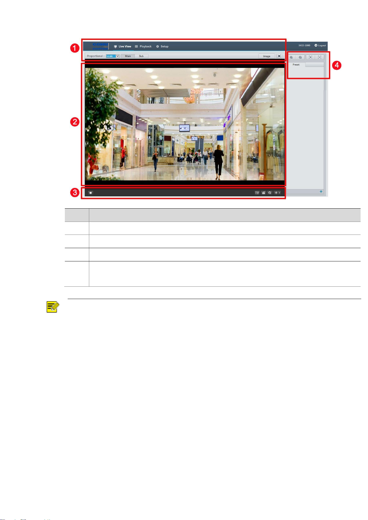
No.
Description
1
Menu
2
Live view window
3
Live view toolbar
4
PTZ control area
Note: This area is available to adjust camera focus and zoom, and preset management.
NOTE!
The displayed live view interface, parameters displayed and value ranges may vary with models.
Please see the actual Web interface for details.
The parameters that are grayed out cannot be modified. For the actual settings, see the Web
interface.
It is recommended that you change the password when you are logged in the first time.
18
 Loading...