

Cohu HD Helios Products 3120 HD Series Installation Manual

HeliosTM Products
INSTALLATION MANUAL 3120
HD
Series
Dome Positioner System
Technical Manual 6X-1109E
July 15, 2014
www.CohuHD.com
info@CohuHD.com

Table of Contents
About this document 3
Additional information and documents related to the camera system 3
FCC compliance 3
Returns 4
Shipment 4
Safety instructions 4
1.0 Introduction 6
1.1 Product Description 6
1.2 Optional Accessories 7
2.0 Installation 8
2.1 Power over Ethernet 9
2.2 System Cable Requirements 10
2.3 18-pin MS Connector and Its Mating System Cable Connector 11
2.4 Alarm Input/Output 11
2.5 CohuHD-Manufactured System Cables (CA275 Series) 12
3.0 Mounting Methods 13
3.1 Wall Mount. CohuHD p/n 7411420-001 13
3.2 Pole Mount. CohuHD p/n 8518-2 14
3.3 Installation Procedures 15
4.0 Quick Check 18
4.1 Computer Requirements 18
4.2 IP Control and Viewing of Camera 18
4.3 Factory Default IP Address and Settings 18
4.4 Factory Default User Names and Passwords 18
4.5 Assigning the New Camera IP Address 19
4.6 Using the CohuONVIFDiscovery Software to Discover the Camera 20
4.7 Checkout Procedure 21
5.0 Maintenance 22
5.1 Camera Housing Pressurization 22
5.1.1 Schrader Valve 23
5.1.2 Pressure Relief Valve 23
6.0 Warranty 24
2 6X-1109E

About this document
This manual contains information on the installation and maintenance of the CohuHDTM HeliosTM 3120
HD
Series Camera System. Please read this manual carefully prior to installation to prevent any accidental
damage or misuse. The manual is available from the CohuHD website at:
http://www.CohuHD.com/Files/install_manuals/3120HD_IM.pdf
The information in this manual is subject to change without notice. Please refer to the above website for
the latest information.
NOTE: All graphics contained within this document, including screenshots and other displays, are for reference use
only and are subject to change.
Additional information and documents related to the camera system
For information on the camera system operation and conguration, please see Operation manual 6X-1090.
The manual is available from the CohuHD website at:
http://www.CohuHD.com/Files/operation_manual/HeliosOperationManual.pdf
Copyright/Intellectual Property Rights statement
Copyright 2014 by CohuHD Costar, LLC. CohuHD Costar, LLC has intellectual property rights to technology
embodied in the product described in this manual.
CohuHD™ and Helios™ are trademarks of CohuHD Costar, LLC.
FCC compliance
This equipment has been tested and found to comply with the limits for a Class A digital device pursuant
to Part 15 of the FCC Rules. These limits are designed to provide reasonable protection against harmful
interference when the equipment is operated in a commercial environment. This equipment generates,
uses, and can radiate radio frequency energy, and, if not installed and used in accordance with the instruction manual, may cause harmful interference to radio communications. Operation of this equipment in
a residential area is likely to cause harmful interference, in which case the user will be required to correct
the interference at his own expense.
This device complies with Part 15 of the FCC Rules. Operation is subject to the following two conditions:
(1) this device may not cause harmful interference, and (2) this device must accept any interference
received, including interference that may cause undesired operation. Changes or modications to this
device void the warranty.
6X-1109E 3

Returns
This item was thoroughly tested and carefully packed at the factory prior to shipping. Upon acceptance by
the carrier, the carrier assumes responsibility for the item’s safe arrival. If you receive the item in a damaged
condition, apparent or concealed, a claim for damage must be made to the carrier.
If a visual inspection shows damage upon receipt of this shipment, it must be noted on the freight bill or
express receipt and the notation signed by the carrier’s agent. Failure to do this can result in the carrier
refusing to honor the claim.
When the damage is not apparent until the unit is unpacked, a claim for concealed damage must be made.
Make a mail or phone request to the carrier for inspection immediately upon discovery of the concealed
damage. Keep all cartons and packing materials.
To return the product to the factory for service, please contact the Customer Service Department for a Return
Material Authorization (RMA) Number.
Prominently display the RMA number on the outside of the shipping container(s) and on paperwork
contained inside. Give a brief description of why the equipment is being returned and list the symptoms of
any problems being experienced with the equipment.
Shipment
IMPORTANT
If the camera needs to be shipped, please use the original packaging material which was designed to
protect the product during transportation. If the original packaging is lost or damaged, please order a
replacement from Customer Service.
Safety instructions
WARNING
PoE (Power over Ethernet) injectors used with this camera system may operate from 90-240 V ac. These
voltages are dangerous. Use extreme care working with equipment connected to these voltages.
WARNING
Voltages that present a shock hazard may exist on PoE circuits. Use caution to avoid direct contact with
exposed, bare Ethernet circuit conductors or connector contacts.
WARNING
Do not remove camera from housing. There are no user serviceable parts inside.
In order to avoid deterioration of the color lter of the CCD and potential discoloration of the image
avoid pointing the camera directly toward the sun or other bright source.
4 6X-1109E
CAUTION

CAUTION
Prolonged exposure to temperatures below -25°C (-13°F) without power applied to the camera is to be
avoided. It will affect operation of the lens and/or motion functions, and can result in damage.
A warm-up time of 90 minutes is required before full operation can be commenced. A reset of the camera module is required after the warm-up period and prior to operating the camera.
IMPORTANT
the packing foam material is selected to provide appropriate shock absorption in shipment,
and that the same material must be used if the camera needs to be shipped (whether on RMA
back to us, or to anywhere else for deployment).
Pressurized camera
This environmentally sealed camera housing is pressurized with dry nitrogen to prevent moisture from affecting the optics or electronics. The nominal internal pressure is 3.5 psi (24.1 kPa).
IMPORTANT
Do not remove the clear plastic tube that protects the pressure relief valve poppet, or the pressurization could be lost. The pressure relief valve is designed to open when the internal pressure exceeds
5 psi (34.5 kPa). Environmental factors such as high temperature or high altitude (including during air
transport) can cause the relief valve to open and bleed off excess pressure, resulting in lower pressure
at normal environmental conditions. See Section 5.1 of this manual for more information on maintaining
the camera housing pressurization.
• Installation must be done by qualied installers, and conform to all local codes.
• It is the user’s responsibility to ensure that the mounting methods are safe and adequate for the
location.
• Use only stainless steel hardware to fasten the mount to an outdoor surface.
• To prevent damage from water leakage when installing a mount outdoors, apply sealant around the
bolt holes between the mount and mounting surface.
• All servicing must be performed by qualied service personnel. The unit contains sensitive
devices that can be damaged by static discharge. To reduce the risk of damage to the unit by static
discharge do not perform any servicing other than described in these instructions. If the unit is
defective, please contact the Customer Service Department for technical assistance.
• It is the sole responsibility of the installer to provide proper installation in compliance with all local
codes and regulations.
• To provide protection against electrical surges induced by lightning, static charges, or any other
cause, the camera and cabling system must be properly grounded to earth. For installation on
a building, the camera must be bonded (that is, provided with a low impedance connection) to the
building’s structural earth ground system. For installation on a metal pole with a proper ground
system at the base, the camera must be bonded to the pole. For installation on a non-grounded or
insulated support, the camera must be grounded with an adequate ground strap or wire between
the camera and a nearby ground system, or to a ground system installed at the base of the support.
Failure to adequately ground the camera may lead to failure of the camera. This applies to low
voltage (i.e. PoE cameras) as well as to 115 Vac cameras. Failures due to surges are not
covered by the warranty , as they are not due to defects in material or workmanship, and it is
the installer’s responsibility to meet these grounding requirements.
6X-1109E 5
1.0 Introduction
The CohuHD 3120HD Camera System is an IP camera system in an IP67
protected pressurized dome positioner. The camera system provides IP video
streams with H.264 and MJPEG compression. The camera provides continuous
360 degree pan (azimuth) motion range with 95 degrees of tilt motion range.
Control interfaces are via Ethernet network connection.
For more information on specications and datasheets, please refer to the
CohuHD website.
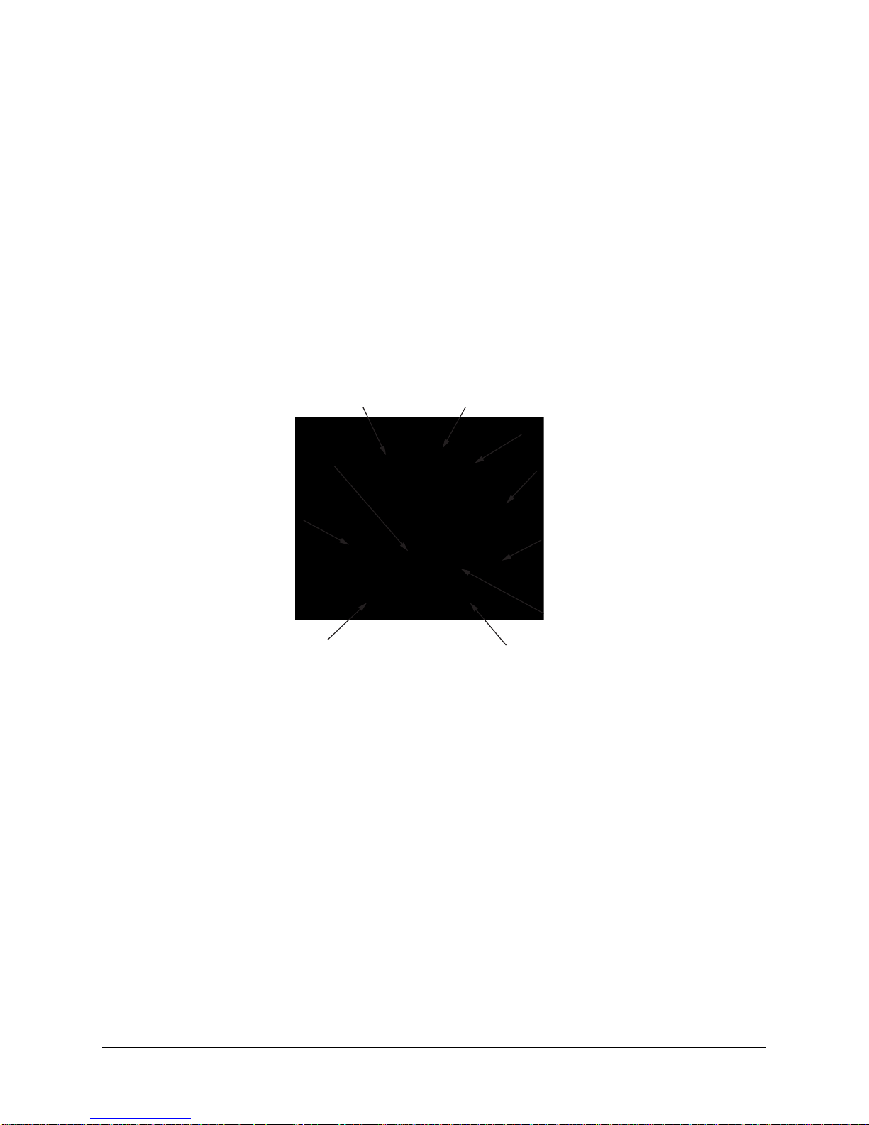
1.1 Product Description
Lock Down Bolts (2)
18 Pin Connector
Schrader Valve
Shown with Installed Cap
Ventilation Hole
(6)
NPT - National Pipe Thread
1.5 NPT Nipple
Quick Disconnect
Top
Safety Strap
Pressure Relief Valve (5 psi)
Shown with Plastic Tubing
Quick Disconnect
Bottom
Sun Shield
Camera Top
NOTE: See Section 3.3 for instructions on the Quick Disconnect disassembling/reassembling.
6 6X-1109E
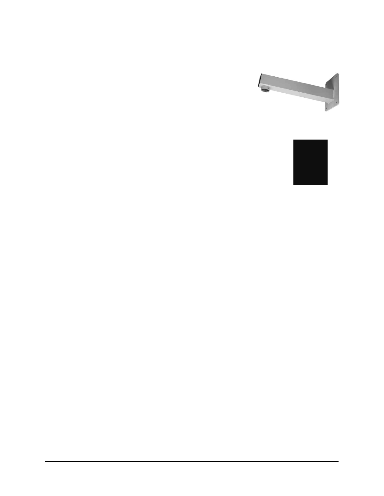
1.2 Optional Accessories
The following optional mounts, cables, and eld connectors (or eld connector kits) are recommended by
CohuHD for camera
system installation, and can be purchased with the camera system.
Mounts:
• Wall: CohuHD p/n 7411420-001
• Pole Mount Kit: CohuHD p/n 8518-2
The kit includes:
Wall mount: CohuHD p/n 7411420-001
Pole mount adapter: CohuHD p/n 7411421-001
Wall Mount
For more information on each type of mount see Chapter 3 of this manual.
Cables:
• CA275 Series. CohuHD p/n 7411275
For more information on cables see Section 2.4 of this manual.
PoE Injector:
Pole Mount Adapter
• PoE Injector: CohuHD p/n 7411539-001
For more information on the injector see Section 2.1 of this manual.
Field Connector:
• Mating Connector: CohuHD p/n 1310230-211 (supplied, if ordered)
For more information on the connector see Section 2.3 of this manual.
Transformer:
• 24 Vac Transformer: CohuHD p/n 7411543-010 (supplied, if ordered)
For more information on the connector see Section 2.3 of this manual.
6X-1109E 7
2.0 Installation
This chapter covers the general installation and cable requirements of the 3120
HD
series.
Before starting installation:
• Choose the installation mounting method. See Chapter 3 of this manual.
• Have the system cable available. CohuHD-manufactured cables can be purchased with the camera
system. See Section 2.4.
• Verify that the cables can be routed to the location of the mounting assembly.
See Chapter 3 for details on the installation procedure for recommended mounts.
HD
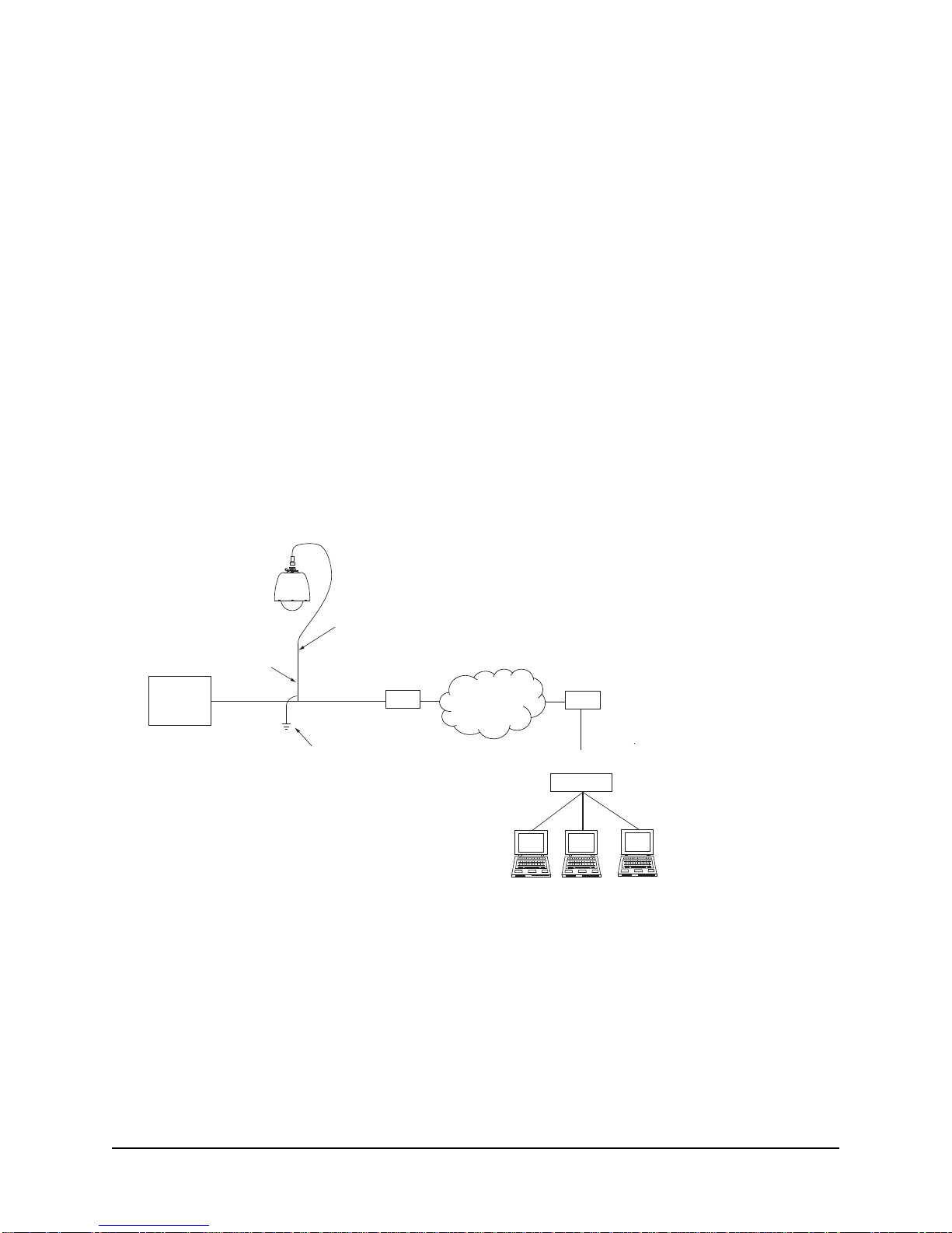
Figures 1, 2 and 3 show interconnection diagrams for the 3120
series cameras:
• Figure 1 shows a setup for the camera system using IP output and 24 Vac power.
• Figure 2 shows a setup for the camera system with PoE-enabled switch.
• Figure 3 shows a setup for the camera system using the PoE injector with non-PoE switch.
These diagrams represent typical installations. Each installation site will have its own unique requirements.
Default IP Address
192.168.2.150
Properly secure the camera system
before the power is applied.
Power
24 Vac ± 10%
@ 3 A min
Cable Shield(s)
System Cable
Earth
Ground
CAT5e
Cable
Router/Switch
WAN
Router/Switch
Network
Figure 1. Interconnection Diagram, 24 Vac
LAN
Switch
8 6X-1109E
 Loading...