

Cohu HD ER 8800 Installation Manual

HeliosTM Products
INSTALLATION MANUAL Series
ER 8800
Long-Range Video Camera
Technical Manual 6X-1110B
July 15, 2014
www.CohuHD.com
info@CohuHD.com

Table of Contents
About this document 3
Additional information and documents related to the camera system 3
Copyright/Intellectual Property Rights statement 3
Support services 3
Returns 4
Safety instructions 5
Grounding 6
1.0 Introduction 7
1.1 Optional Accessories 7
2.0 Installation 8
2.1 Test Cable Requirements 9
2.2 CohuHD-Manufactured Test Cables (ER8900E1) 9
2.3 Connector Pinouts 9
3.0 Mounting Methods 10
3.1 Standalone Camera System Mounting Methods 12
3.1.1 Pedestal Mount Installation. CohuHD p/n 8186-1 12
3.1.2 Wall Mount Installation. CohuHD p/n 8186-2 13
3.1.3 Pole Mount Installation. CohuHD p/n 8186-3 14
3.1.4 Corner Mount Installation. CohuHD p/n 8186-4 15
3.1.5 Parapet Mount Installation. CohuHD p/n 8186-5 16
3.1.6 Installation Procedure 17
3.2 Overall Dimensions 19
3.3 Mounting Hole Pattern 19
3.4 Mounting Brackets Dimensions 20
4.0 Quick Check 24
4.1 Control and Viewing of Camera 24
4.2 Checkout Procedure 24
5.0 Maintenance 25
5.1 Camera Head Housing Pressurization 25
5.1.1 Schrader Valve 26
5.1.2 Pressure Relief Valve 26
5.1.3 Pressurizing Procedure 26
6.0 Warranty 27
7.0 ER8800 Series Variants Applicable to the Manual 27
2 6X-1110B

About this document
This manual contains information on the installation and maintenance of the CohuHD ER8800 Series Long
Range Standalone Camera System. Please read this manual carefully prior to installation to prevent any
accidental damage or misuse. The manual is available from the CohuHD website at:
http://www.CohuHD.com/Files/install_manuals/ER8800_IM.pdf
The information in this manual is subject to change without notice. Please refer to the above website for
the latest information.
NOTE: All graphics contained within this document, including screenshots and other displays, are for reference use
only and are subject to change.
Additional information and documents related to the camera system
For additional information on WinMPC, contact Customer Service.
Copyright/Intellectual Property Rights statement
Copyright 2014 by CohuHD Costar, LLC. CohuHD Costar , LLC has intellectual property rights to technology
embodied in the product described in this manual.
CohuHD™ and Helios™ are trademarks of CohuHD Costar, LLC.
Support services
Please contact the Customer Service Department for technical assistance.
6X-1110B
3

Returns
This item was thoroughly tested and carefully packed at the factory prior to shipping. Upon acceptance by
the carrier, the carrier assumes responsibility for the item’ s safe arrival. If you receive the item in a damaged
condition, apparent or concealed, a claim for damage must be made to the carrier.
If a visual inspection shows damage upon receipt of this shipment, it must be noted on the freight bill or
express receipt and the notation signed by the carrier’s agent. Failure to do this can result in the carrier
refusing to honor the claim.
When the damage is not apparent until the unit is unpacked, a claim for concealed damage must be made.
Make a mail or phone request to the carrier for inspection immediately upon discovery of the concealed
damage. Keep all cartons and packing materials.
To return the product to the factory for service, please contact the Customer Service Department for a Return Material Authorization (RMA) Number.
Prominently display the RMA number on the outside of the shipping container(s) and on paperwork contained inside. Give a brief description of why the equipment is being returned and list the symptoms of any
problems being experienced with the equipment.
For shipment, send package with enough foam padding or other packing material to prevent damage during
shipping. The original shipping carton is a good container if it has not been damaged.
Shipment
IMPORTANT
If the camera needs to be shipped, please use the original packaging material which was designed to
protect the product during transportation. If the original packaging is lost or damaged, please order a
replacement from Customer Service.
4 6X-1110B

Safety instructions
WARNING:
Do not open enclosures. There are no user-serviceable parts inside.
CAUTION:
Inordertoavoiddeteriorationofthecolorlterofthesensorandpotentialdiscolorationoftheimage
avoid pointing the camera directly toward the sun or other bright source.
CAUTION:
Secure the camera system before the power is applied.
• Installationmustbedonebyqualiedinstallers,andconformtoalllocalcodes.
• It is the user’s responsibility to ensure that the mounting methods are safe and adequate for the
location.
• Use only stainless steel (SS) hardware to fasten the mount to an outdoor surface.
• Allservicingmustbeperformedbyqualiedservicepersonnel.Proceduresinthismanualdonot
require entry into the housing of the camera system. The unit contains potential high voltage. It also
contains sensitive devices that can be damaged by static discharge. To reduce the risk of electric
shock and damage to the unit by static discharge do not perform any servicing other than described
in these instructions. If the unit is defective, please contact the Customer Service Department for
technical assistance.
• It is the sole responsibility of the installer to provide proper installation in compliance with all local
codes and regulations.
6X-1110B
5

Grounding
• To provide protection against electrical surges induced by lightning, static charges, or any other
cause, the camera and cabling system must be properly grounded to earth. For installation on a
building, the camera must be bonded (that is, provided with a low impedance connection) to the
building’s structural earth ground system. For installation on a metal pole with a proper ground
system at the base, the camera must be bonded to the pole. For installation on a non-grounded or
insulated support, the camera must be grounded with an adequate ground strap or wire between
the camera and a nearby ground system, or to a ground system installed at the base of the support. Failure to adequately ground the camera may lead to failure of the camera. This applies to
low voltage (i.e. PoE cameras) as well as to 115 Vac cameras. Failures due to surges are not
covered by the warranty , as they are not due to defects in material or workmanship, and it is
the installer’s responsibility to meet these grounding requirements.
• All system cables must be shielded, and the shield(s) must be bonded to earth ground.
6 6X-1110B
1.0 Introduction
The CohuHD’s ER8800 series includes a standalone camera system with a high performance zoom lens
made for long range applications. With long range lens and accessory options, the ER8800 line is designed
for the rigorous environments and requirements for border, port, and shipboard security, as well as range
safety, intruder detection, and other targeting or tracking applications.
Thexedcamerasystem:
• Complies with NEMA TS 2 standards for shock and vibration. For ingress protection, the camera
system complies with the IP67 standard.
For more information on specications and datasheets, please refer to specic product pages at CohuHD’s
website.
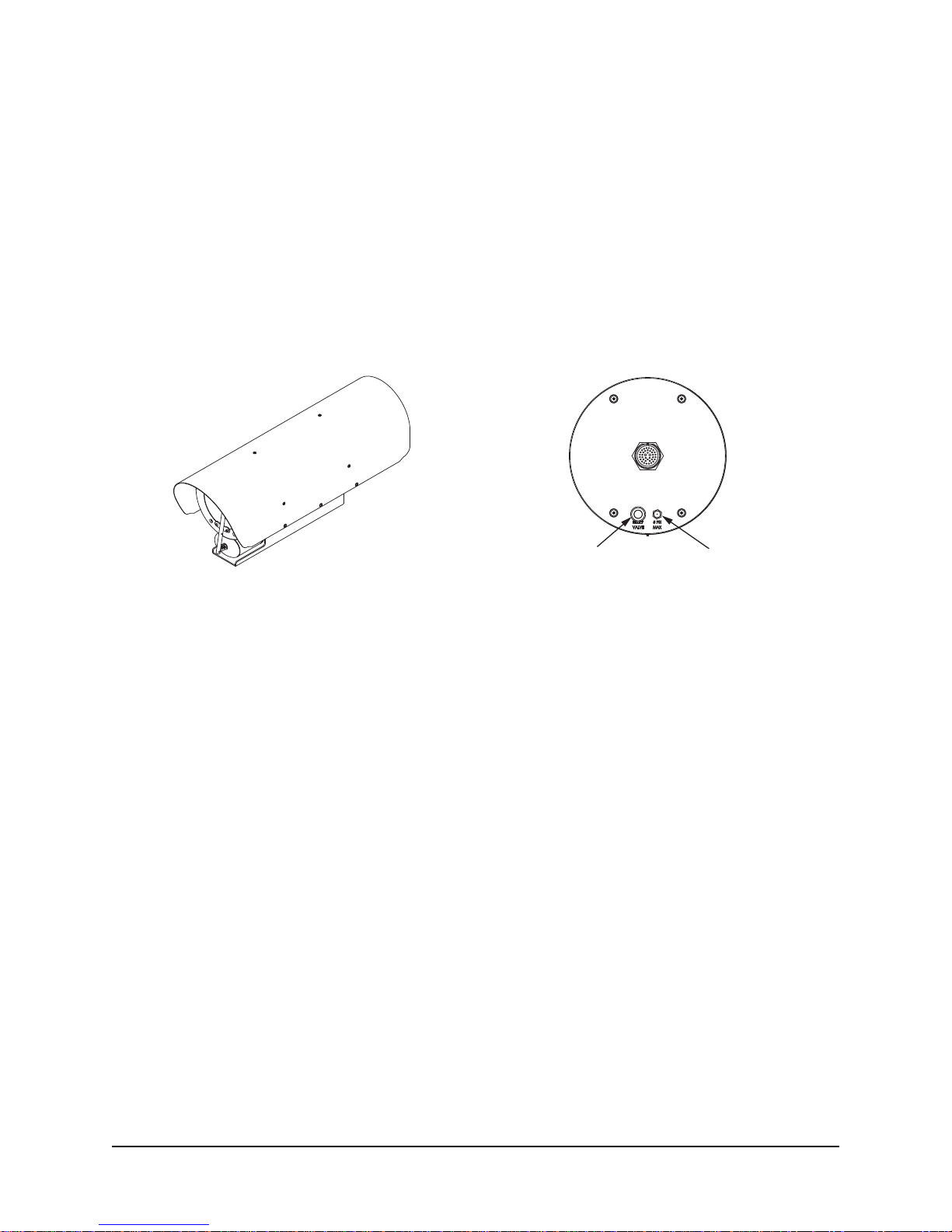
ER8800 Standalone Camera System
Pressure Relief Valve
(shown with plastic tubing)
ER8800 Camera System Rear Plate
Schrader Valve
1.1 Optional Accessories
Thefollowingoptionalcablesandeldconnectors(oreldconnectorkits)arerecommendedbyCohuHD
for camera system installation, and can be purchased with the camera system.
Cables:
• ER8900E1 Series
For more information on cables see Sections 2.1 and 2.2 of this manual.
Field Connector or Connector Kit:
• Mating Connector: PT06A-20-39S(SR) or equivalent, CohuHD p/n:1310230-005 (supplied, if ordered).
For more information on the connector see Section 2.3.
24 Vdc Power Supply:
• Power supply PFC-500-27.
6X-1110B
7
2.0 Installation
This chapter covers the general installation and cable requirements of the ER8800 series.
NOTE: All graphics contained within this document, including screenshots and other displays, are for reference use
only and are subject to change.
Before starting installation:
• Choose the installation mounting method. See Chapter 3 of this manual.
• Have the system cable available. CohuHD-manufactured cables can be purchased with the cam-
era system. See Section 2.2.
• Verify that the system cable can be routed to the location of the mounting assembly.
See Chapter 3 for details on the installation procedure for recommended mounts.
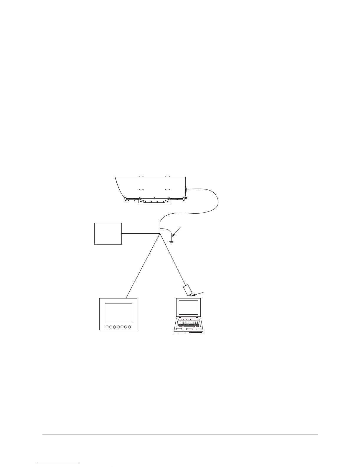
Figure 1 shows an interconnection diagram for the ER8800 series camera systems. The diagram repre-
sents typical installations. Each installation site will have its own unique requirements.
Properly secure the camera
system before the power is
applied.
System Cable
Earth
Power
Coax Cable
Analog
Monitor
Ground
Serial Cable
422
RS-232/422 Converter
232
Direct plug-in
to computer
serial port
Figure 1. Interconnection Diagram
NOTE: For a PC without a serial port, CohuHD recommends USB-RS232 adapter cable: p/n ES-U-1001-
R10(R100).
8 6X-1110B
2.1 Test Cable Requirements
To build the test cable, CohuHD recommends:
• AC38 Composite Cable. The maximum recommended cable length is 22 m (75’).
2.2 CohuHD-Manufactured Test Cables (ER8900E1)
CohuHD-manufactured cables are available for ER8800 series camera systems operating from 24 Vdc.
The ER8900E1 cable is intended for applications where the 24 Vdc power supply is located within 20 feet
of the camera.
Please contact the Customer Service Department for technical assistance.
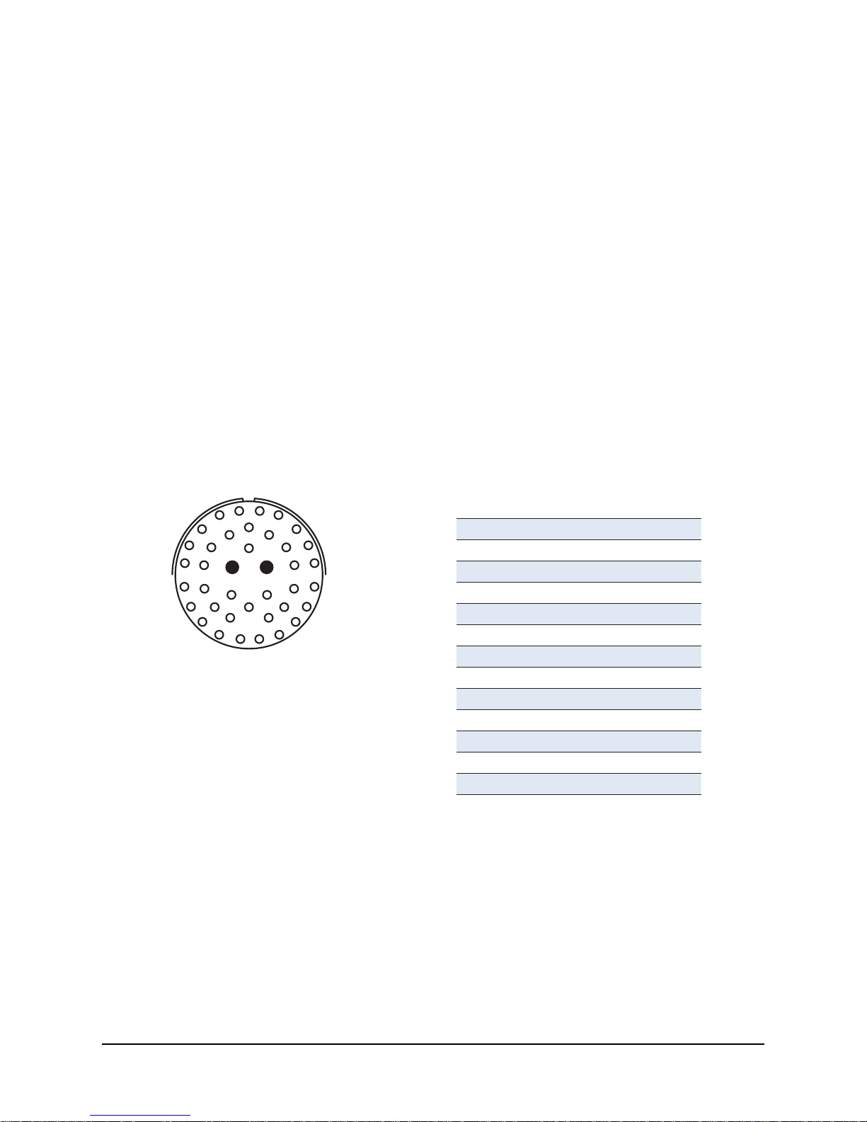
2.3 Connector Pinouts
A single connector on the rear camera panel provides all electrical connections for the camera system.
Table 1 lists pin functions of the camera connector, which are identical to the corresponding pin functions
of the mating connector.
Camera Connector - Mil Spec Con: PT07C-20-39P connector, CohuHD p/n: 1310225-004. Mating connector - PT06E-20-39S(476) or equivalent, CohuHD p/n:1310230-105 (supplied, if ordered).
Table 1. MS Connector Pinouts
W
V
U
j
T
i
S
R
r
h
g
q
P
f
N
M
Figure 2. Pin Location Diagram
MS-type Connector
View from the front (mating) side
A
B
X
Y
k
p
e
L
K
C
Z
D
m
a
E
b
n
F
c
G
d
H
J
CAMERA CONNECTOR
Pin
E
i
b
k
H
G
M
N
K
J
L
Function
TXD
RXD
Data Ground
Data Ground
+24 Vdc Camera Power
Camera Power Return
+24 Vdc Camera Heater Power
Heater Power Return
Video
Video Ground
Overall Cable Shield
6X-1110B
9
 Loading...