

Cohu HD 4260HD Installation Manual
RISE™ Series
4260HD
Camera Positioning System
Installation Manual 6x-1114D
www.CohuHD.com

- 2 -

Table of Contents
1.0 General Information 5
1.1 About this document 5
1.2 Additional information and documents related to the camera system 5
1.3 Copyright/Intellectual Property Rights Statement 5
1.4 FCC compliance 5
1.5 Support services 5
1.6 Returns 5
1.7 Shipment 6
2.0 Safety Instructions 7
2.1 Important Information 7
2.2 Grounding 7
3.0 Installation 9
3.1 4260HDCamera Positioner System Overview 9
3.2 Optional Accessories 9
3.3 4260HD Interconnection Diagrams 11
3.3.1 Interconnection Diagram with PoE++ Power Supply and Non-PoE Switch. 11
3.3.2 Interconnection Diagram with PoE++ Power Supply, I/O and Non-PoE Switch. 11
3.3.3 Interconnection Diagram with 24 Vac Power Supply, Analog and IP Output. 12
3.3.4 Interconnection Diagram with 24 Vac Power Supply, Analog and IP Output. 12
3.3.5 Interconnection Diagram with 120 Vac Power Supply. 13
3.3.6 Interconnection Diagram with 120 Vac Power Supply. MS or AMP Connectors 13
3.3.7 Power over Ethernet (PoE++) 14
3.4 4260HD Cables 15
3.4.1 4260HD Models and Available Cable Functions 15
3.4.2 RJ-45 Connector Pinouts (Models 4261HD, 4262HD, and 4263HD) 16
3.4.3 RJ-45 Connector Pinouts (Models 4264HD, 4265HD, 4266HD, 4268HD, and 4269HD) 16
3.4.4 18-pin MS Type (Metal) Connector and its Mating System Cable Connector (Models 4263HD,
4265HD, 4266HD, 4267HD and 4268HD) 16
3.4.4.1 MS Connector Pinouts (Models 4263HD and 4265HD) 17
3.4.4.2 MS Connector Pinouts (Model 4266HD) 17
3.4.4.3 MS Connector Pinouts (Model 4267HD) 18
3.4.4.4 MS Connector Pinouts (Model 4268HD) 18
3.4.5 Stripped Leads Wire Colors and Corresponding Functions (Models 4262HD and 4264HD) 19
3.4.6 16-pin Amp Type (Plastic) Connector Kit and its Mating System Cable Connector Kit (Model
4269HD) 19
3.4.6.1 Amp Connector Pinouts (Model 4269HD) 20
3.4.7 Digital Inputs/Outputs (DIO) 20
3.4.8 Field Cables 21
3.4.9 4260HD CohuHD- Manufactured System Cables 23
3.4.9.1 4266HD Cable Compatibility 24
3.5 4260HD Camera System Mounting Methods 27
3.5.1 Standard and Inverted Mounting Methods 27
3.5.1.1 Inverted Mount Configuration 27
3.5.2 Camera System Mounts 27
3.6 4260HD Camera System Mounting Diagrams 29
- 3 -

3.6.1 Large Pedestal Adapter for the PoE and 24 Vac Power Option 29
3.6.2 Large Pedestal Plate for the 120 Vac Power Option 29
3.6.3 Wall Mount Installation 30
3.6.4 Pole Mount Installation 30
3.6.5 Corner Mount Installation 31
3.6.6 Parapet Mount Installation 31
3.7 Installation Procedure 33
3.7.1 Instructions on How to Assemble the Waterproof Shielded RJ45 Coupler 35
3.8 Overall Dimensions and Mounting Base Hole Pattern 36
3.9 Mounting Brackets Dimensions 38
3.9.1 Large Pedestal Plate 38
3.9.2 Large Pedestal Adapter 38
3.9.3 Mount Adapter 39
3.9.4 Wall Mount 39
3.9.5 Pole Mount 39
3.9.6 Corner Mount 40
3.9.7 Parapet Mount 40
4.0 Getting Started 41
4.1 Recommended Computer Specifications 41
4.2 System Requirements 41
4.3 Factory Default IP Address and Settings 41
4.4 Factory Default User Names and Passwords 41
4.5 Assigning the Static IP Address 42
4.6 Assigning the New Camera IP Address 44
4.7 Using the RISE Camera Discovery Tool 45
4.8 Accessing the Camera Using Web Interface 47
4.9 Users' Accounts 48
5.0 Maintenance 49
5.1 Maintenance 49
5.2 Wiper Unit 49
6.0 Warranty 50
- 4 -

1.0 General Information
1.1 About this document
This document contains information on how to install and maintain the 4260HD Series Camera Positioning
System.Please read this manual carefully prior to installation to prevent any accidental damage or misuse.
The manual is available from the CohuHD website at
http://www.cohuhd.com/Support/Product-Documentation
The information in this manual is subject to change without notice. Please refer to the above website for the
latest information.
Note: All graphics contained within this document, including screenshots and other displays, are for reference use only and are subject to change.
1.2 Additional information and documents related to the camera system
For information on the camera system operation, see Operation manual 6x-1119. The manual is available from
the CohuHD website at:
http://www.cohuhd.com/Support/Product-Documentation
1.3 Copyright/Intellectual Property Rights Statement
Copyright 2015, 2016, 2017 CohuHD Costar, LLC. CohuHD Costar, LLC has intellectual property rights to
technology embodied in the product described in this manual.
CohuHD Costar™, RISE™, and Command Core™ are trademarks of CohuHD Costar, LLC.
1.4 FCC compliance
This equipment has been tested and found to comply with the limits for a Class A digital device pursuant to
Part 15 of the FCC Rules. These limits are designed to provide reasonable protection against harmful interference when the equipment is operated in a commercial environment. This equipment generates, uses, and
can radiate radio frequency energy, and, if not installed and used in accordance with the instruction manual,
may cause harmful interference to radio communications. Operation of this equipment in a residential area is
likely to cause harmful interference, in which case the user will be required to correct the interference at his
own expense.
Operation is subject to the following two conditions:
(1) this device may not cause harmful interference, and (2) this device must accept any interference received,
including interference that may cause undesired operation. Changes or modifications to this device void the
warranty.
1.5 Support services
Please contact the Customer Service Department for technical assistance.
1.6 Returns
This item was thoroughly tested and carefully packed at the factory prior to shipping. Upon acceptance by the
carrier, the carrier assumes responsibility for the item’s safe arrival. If you receive the item in a damaged condition, apparent or concealed, a claim for damage must be made to the carrier.
- 5 -

If a visual inspection shows damage upon receipt of this shipment, it must be noted on the freight bill or
express receipt and the notation signed by the carrier’s agent. Failure to do this can result in the carrier refusing to honor the claim.
When the damage is not apparent until the unit is unpacked, a claim for concealed damage must be made.
Make a mail or phone request to the carrier for inspection immediately upon discovery of the concealed damage. Keep all cartons and packing materials.
To return the product to the factory for service, please contact the Customer Service Department for a Return
Material Authorization (RMA) Number.
Prominently display the RMA number on the outside of the shipping container(s) and on paperwork contained
inside. Give a brief description of why the equipment is being returned and list the symptoms of any problems
being experienced with the equipment.
1.7 Shipment
Important:If the camera needs to be shipped, please use the original packaging material which was
designed to protect the product during transportation. If the original packaging is lost or damaged, please
order a replacement from Customer Service.
- 6 -

2.0 Safety Instructions
2.1 Important Information
Warning: Do not remove the covers or housing. There are no user-serviceable parts inside.
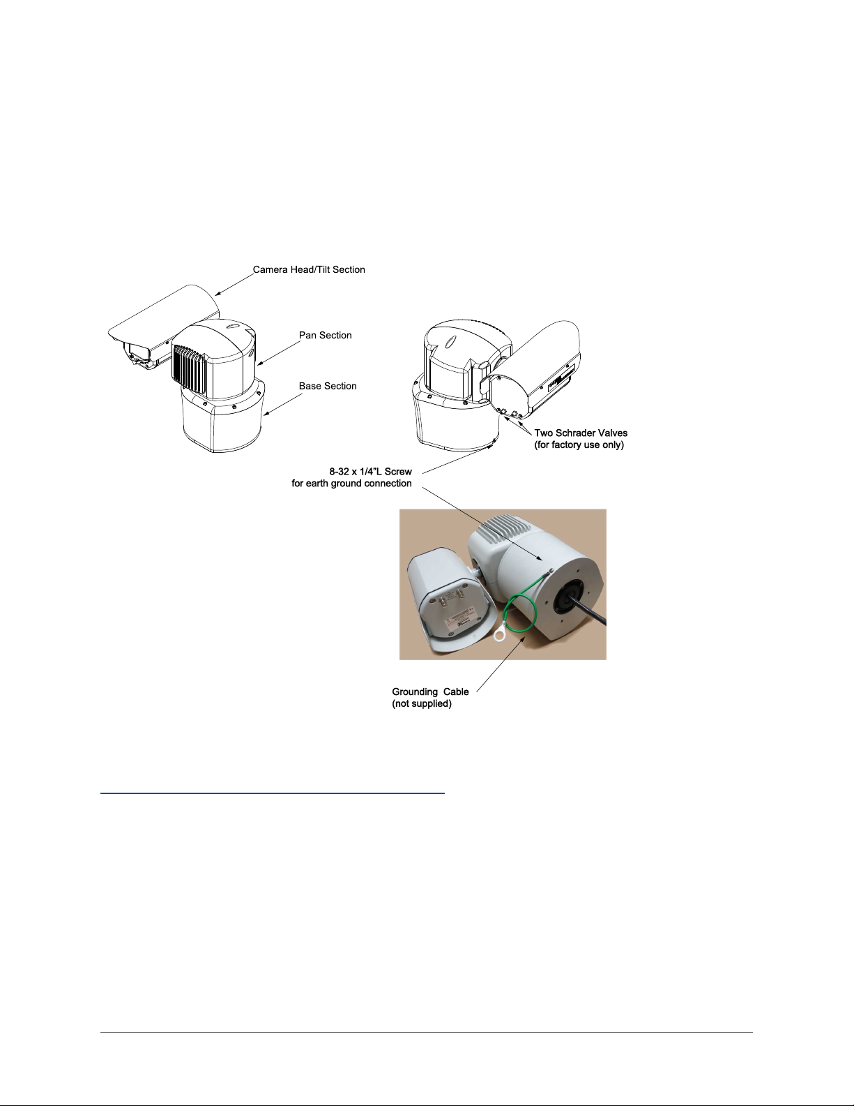
Warning:The Schrader Valves on the camera head's back plate are for factory use only. Do not attempt to
add any gas to the camera head.
Warning: PoE++ (Power over Ethernet) injectors used with this camera system may operate from 100-240
Vac. These voltages are dangerous. Use extreme care working with equipment connected to these voltages.
NFPA 70 (Articles 800.30 and 830.30), National Electric Code®requires that a listed primary protector be
installed on the conductors of outdoor communication circuits entering a premises, as close as possible to
the point of entrance. The primary protector must be appropriate to the circuit type (PoE, PoE++, or Ethernet).
Warning: Voltages that present a shock hazard may exist on PoE circuits. Use caution to avoid direct contact with exposed, bare Ethernet circuit conductors or connector contacts.
Warning: Some models of this camera system operate from 120 or 24 Vac. Use care working with equipment connected to 120 or 24 Vac.
Warning: The camera system is operated via remote computer control and may move rapidly and unexpectedly. Remove power from the camera system before servicing and whenever working near the camera system.
Warning: Do not use y-cables or other non-standard wiring schemes.
Caution: In order to prevent damage or deterioration of the optical system avoid pointing the camera system
directly toward the sun.
l Installation must be done by qualified installers, and conform to all local codes and regulations.
l All servicing must be performed by qualified service personnel. Procedures in this manual do not
require entry into the housing of the camera system. The unit contains sensitive devices that can be
damaged by static discharge. To reduce the risk of electric shock and damage to the unit by static discharge do not perform any servicing other than described in these instructions. If the unit is defective,
please contact the Customer Service Department for technical assistance.
l It is the user’s responsibility to ensure that the mounting methods are safe and adequate for the loca-
tion.
l Use only stainless steel (SS) hardware to fasten the mount to an outdoor surface.
2.2 Grounding
l To provide protection against electrical surges induced by lightning, static charges, or any other cause,
the camera and cabling system must be properly grounded to earth. For installation on a building, the
camera must be bonded (that is, provided with a low impedance connection) to the building’s structural
earth ground system. For installation on a metal pole with a proper ground system at the base, the
- 7 -

camera must be bonded to the pole. For installation on a non-grounded or insulated support, the camera must be grounded with an adequate ground strap or wire between the camera and a nearby ground
system, or to a ground system installed at the base of the support. Failure to adequately ground the
camera may lead to failure of the camera. This applies to low voltage (24 Vac and PoE cameras) as
well as to 120 Vac cameras. Failures due to surges are not covered by the warranty, as they are
not due to defects in material or workmanship, and it is the installer’s responsibility to meet
these grounding requirements.
l All system cables must be shielded, and the shield(s) must be bonded to earth ground.
l The grounding screw on the camera’s base must be connected to earth ground using minimum 16
AWG wire and bonded to earth ground as close to the camera system as possible.
- 8 -
3.0 Installation
3.1 4260HDCamera Positioner System Overview
The 4260HDCamera System is an IP camera system contained within three independently sealed and environmentally protected sections. The camera system provides IP video streams with H.264 and MJPEG compression. The positioning system provides continuous 360° pan (azimuth) motion range with +/- 95° of tilt
(elevation). Control interfaces are via Ethernet network connection or optional RS422 serial control.
For detailed specifications, download the camera's datasheet from the CohuHD website:
http://www.cohuhd.com/Support/Product-Documentation.
3.2 Optional Accessories
The following optional accessories are recommended by CohuHD and can be purchased with the camera system.
Mounts
l Large Pedistal Adapter: CohuHD p/n 7411444-003
l Large Pedestal Plate: CohuHD p/n 8481-9
l Wall: CohuHD p/n 8425-7
l Pole: CohuHD p/n 8503-0
l Corner: CohuHD p/n 8503-1
l Parapet: CohuHD p/n 8503-2
- 9 -

Cables
l See "4260HD CohuHD- Manufactured System Cables " on page 23.
PoE ++ Injectors
l CohuHD p/n 7412007-001, 120 Vac
l CohuHD p/n 7412007-002, 230 Vac
l CohuHD p/n 7412007-003,
See "Power over Ethernet (PoE++)" on page 14 .
Field Connectors
l MS Mating Connector: Amphenol p/n PT06E-14-18S(476) or equivalent, CohuHD p/n 1310230-111.
l AMP Mating connector kit:
1. 16-pin Connector, Plug. CohuHD p/n 1310307-009, Amphenol p/n 206037-1 or equivalent.
2. Backshell. CohuHD p/n 1310307-103, Amphenol p/n 206070-8 or equivalent.
3. Contacts
Waterproof RJ45 Coupler
l Waterproof RJ45 Coupler: VPI CAT5e-WTP-FF or equivalent, CohuHD p/n 7610203-001.
24 Vac Power Transformer
l AC Outdoor Power Supply: Altronix WayPoint-10A or equivalent, CohuHD p/n 7411543-010.
Wiper Arm
l Wiper Arm Assembly: CohuHD p/n 8190-5. See " Maintenance" on page 49.
Outdoor Surge Protective Device for PoE and Ethernet
l Surge Protective Device, Power over Ethernet (PoE/PoE+): Edco CAT6-POE-1 or equivalent,
CohuHD p/n 7411708-005.
Outdoor Surge Protective Device for PoE++
l Surge Protective Device, Power over Ethernet (PoE++): PD-OUT/SP11 or equivalent, CohuHD p/n
7412009-001.
- 10 -
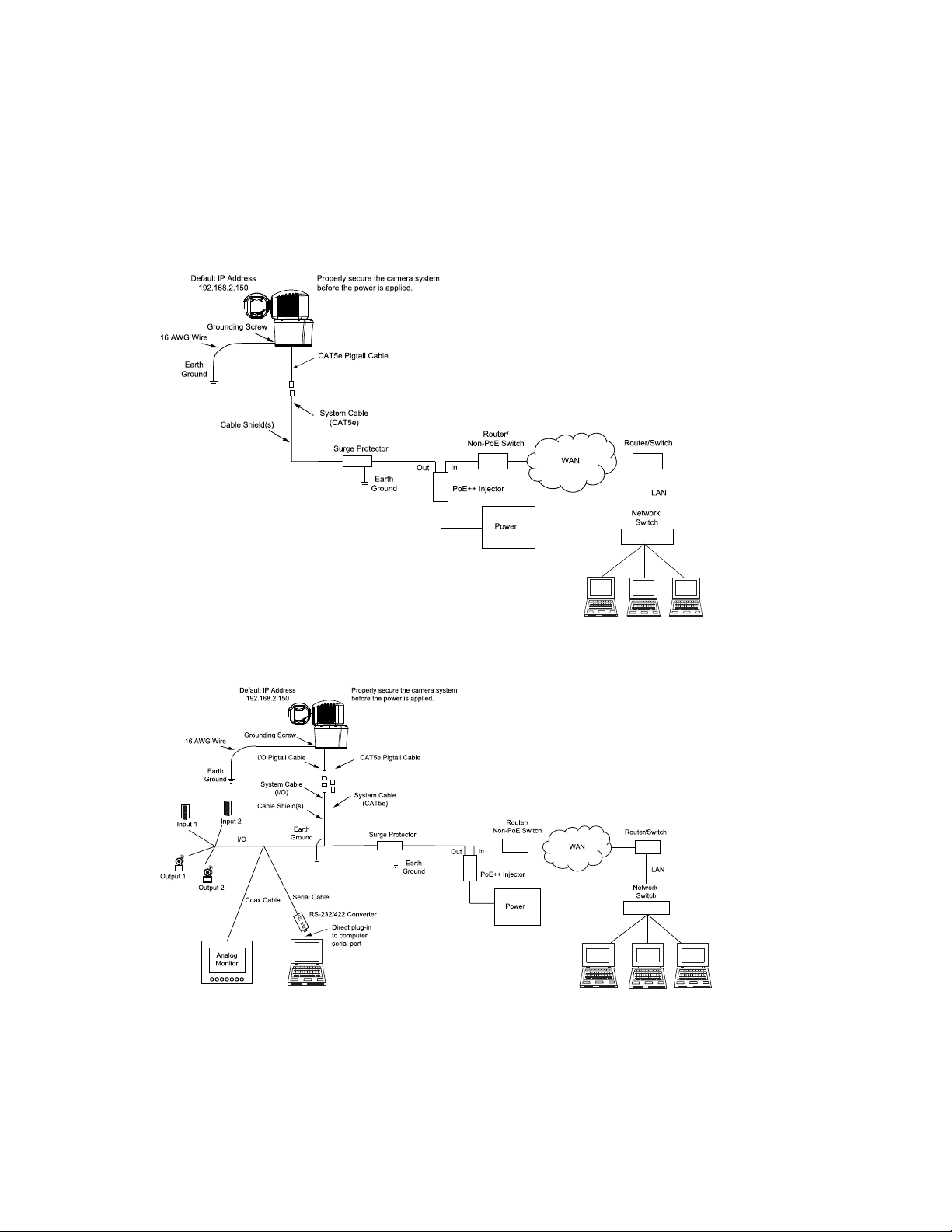
3.3 4260HD Interconnection Diagrams
See "Safety Instructions" on page 7. See " Installation Procedure" on page 33 for the camera grounding procedure.
The following are interconnection diagrams for the 4260HD camera system:
3.3.1 Interconnection Diagram with PoE++ Power Supply and Non-PoE Switch.
3.3.2 Interconnection Diagram with PoE++ Power Supply, I/O and Non-PoE Switch.
- 11 -
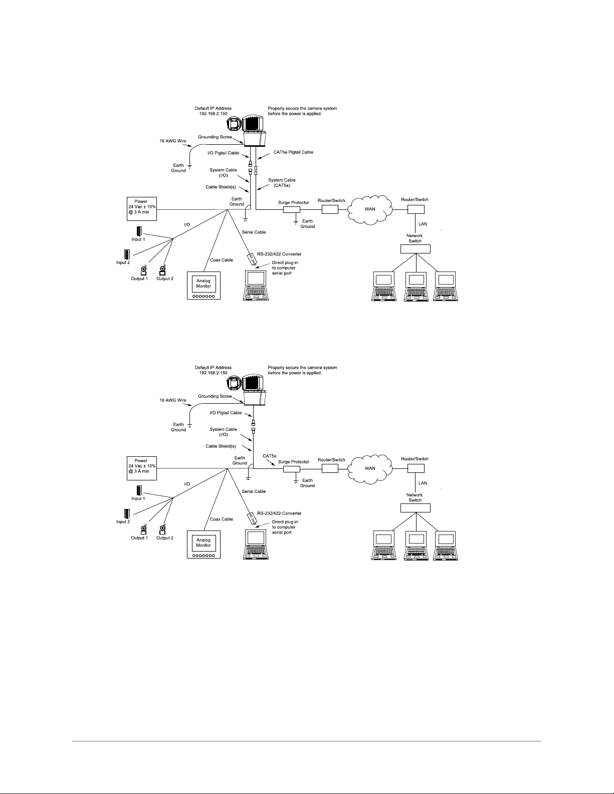
3.3.3 Interconnection Diagram with 24 Vac Power Supply, Analog and IP Output.
3.3.4 Interconnection Diagram with 24 Vac Power Supply, Analog and IP Output.
- 12 -
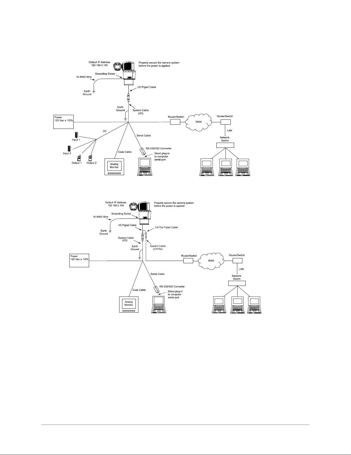
3.3.5 Interconnection Diagram with 120 Vac Power Supply.
3.3.6 Interconnection Diagram with 120 Vac Power Supply. MS or AMP Connectors
- 13 -

3.3.7 Power over Ethernet (PoE++)
The 4260HD camera system is compliant with the LTPoE++™ (Linear Technology) specification.
LTPoE++ maintains interoperability with existing PoE and PoE+ standard equipment and specifies backward
compatibility with IEEE 802.3af (PoE) and 802.3at (PoE+) power sourcing equipment (PSE) and powered
devices (PD). It expands the power available at the PD to four different power levels: 38.7 W, 52.7 W, 70 W
and 90 W.
Power to the camera is supplied through the network cable. Two types of PoE++ implementations are specified:
l Endspan PoE++: Power is applied directly by the switch to the camera. This method requires the
deployment of a PoE++ enabled switch.
l Midspan PoE++: Power is supplied by an injector placed between an existing non-PoE++ switch and
the camera.
PoE++ injectors can be ordered from CohuHD. Please refer to the CohuHD website in the 4260HD series
specifications section for ordering information. The PoE++ injector selected for use with 4260HD must meet
the following requirement:
l Be compatible with the LTPoE++ specification. Please refer to the following website for more infor-
mation: http://www.linear.com/products/poe_powered_device_(pd)
- 14 -

3.4 4260HD Cables
3.4.1 4260HD Models and Available Cable Functions
The 4260HD camera system is built with one or two cables attached to the camera base for electrical connection. The 4260HD camera model number identifies the type(s) of cable(s) the camera system requires.
The 4260HD camera system can be ordered with a combination of two cables:
l CAT5e (Ethernet and PoE++) Pigtail Cable: Belden 7919A shielded CAT5e pigtail cable terminated
into an RJ-45 connector.
l Multi-conductor Input/Output (I/O) Pigtail Cable: 36” long custom CohuHD multi-conductor pigtail
cable. The I/O cable is made with either stripped (prepared) leads, an MS type (metal) connector or
AMP type (plastic) connector.
The following pictures show camera models with cables.
4260HD Models and Available Cables
The following table lists the cable functions and the camera models where these functions are available.
4260HD Models and Available Cable Functions
Camera
Cables
CAT5e with
RJ-45 Connector
I/O with MS
Connector,
AMP Connector or
Stripped
Leads
*Note: 4266HD, 4267HD - The Ethernet signalgoes thr ough the MS connector.
4267HD)" on page 18.See "MS Connector Pinouts (Model 4266HD)" on page 17
Note: The symbol"-" means that the cable function is not available for the camera model.
Function
Ethernet yes yes yes yes yes * * yes yes
PoE++ PoE++ PoE++ PoE++ - - - - - -
DIO - yes yes yes yes yes yes - -
RS422
Serial
Analog
Video
Power
(120Vac or
24 Vac)
4261HD4262HD4263HD4264HD4265HD4266
- yes yes yes yes yes yes yes yes
- yes yes yes yes yes yes yes yes
- - - 24 Vac 24 Vac 24 Vac 120 Vac 120 Vac 120 Vac
Models
HD
4267HD4268HD4269
See "MS Connector Pinouts (Model
.
HD
- 15 -

3.4.2 RJ-45 Connector Pinouts (Models 4261HD, 4262HD, and 4263HD)
RJ-45 Connector
Pin Function
1 Ethernet TX+
2 Ethernet TX-
3 Ethernet RX+
6 Ethernet RX-
5 PoE++ VPort-
4 PoE++ VPort+
7 PoE++ VPort+
8 PoE++ VPort-
3.4.3 RJ-45 Connector Pinouts (Models 4264HD, 4265HD, 4266HD, 4268HD, and 4269HD)
RJ-45 Connector
Pin Function
1 Ethernet TX+
2 Ethernet TX-
3 Ethernet RX+
6 Ethernet RX-
5 Not Connected
4 Not Connected
7 Not Connected
8 Not Connected
Note: Model 4267HD has no RJ-45 connector.
3.4.4 18-pin MS Type (Metal) Connector and its Mating System Cable Connector (Models 4263HD, 4265HD, 4266HD, 4267HD and 4268HD)
Camera connector: Amphenol p/n PT06E-14-18P(476) or equivalent, CohuHD p/n 1310230-117.
Mating connector: Amphenol p/n PT06E-14-18S(476) or equivalent, CohuHD p/n 1310230-111 (supplied, if
ordered).
- 16 -
 Loading...