

Cohu HD 3120HD series, 3920SD series, 3920HD series, 3960HD series, 3720HD series Operation Manual
...
HeliosTM Products
OPERATION MANUAL Series
3120HD
3720HD
3920
3930
3960
5970
8800
HD\SD
HD
HD\SD
SD
HD
Technical Manual 6X-1090K
July 15, 2014
www.CohuHD.com
info@CohuHD.com

Table of Contents
About this document 3
Additional information and documents related to the camera system 3
FCC compliance 3
Support services 3
Returns 4
1.0 Getting Started 5
1.1 Factory Default IP Address and Settings 5
1.2 System Requirements 5
1.3 Recommended Computer Specications 5
1.4 3960HD/3960SD/5970SD Interconnection Diagram 6
1.5 3930HD Interconnection Diagram 7
1.6 3920HD/3920SD Interconnection Diagram 9
1.7 3120HD/3720HD Interconnection Diagram 10
1.8 8800HD Interconnection Diagram 12
1.9 Assigning the Static IP Address 13
2.0 Accessing the Camera Using the Helios Web Interface 15
Assigning the New Camera IP Address 17
Using the CohuONVIFDiscovery Software to Discover the Camera 18
2.1 Helios Web Interface Home Page Overview 19
2.1.1 Video Control Area 20
2.1.2 Live Video Control 20
2.1.3 LED Indicators 20
2.1.4 On-Screen Display 20
2.2 Setup 21
2.2.1 Conguration 21
2.2.1.1 Communication 22
2.2.1.2 Stream 1 23
2.2.1.3 Stream 2 24
2.2.1.4 OSD (On-Screen Display) 26
2.2.1.5 Time 27
2.2.1.6 User Settings 28
2.2.2 Change Password 30
2.2.3 Properties 31
2.2.3.1 Properties (Applies to 3960HD/3960SD/3920HD/3920SD/3930HD/3720HD/3120HD) 31
2.2.3.2 Properties (Applies to 5970SD) 33
2.2.3.3 Properties (Applies to 8800HD) 38
2.2.4 Upgrade 40
2.2.4.1 Firmware Upgrade 41
2.2.4.2 Web Interface Upgrade 42
2.3 Stream 43
2.4 Lens 43
2.4.1 Lens (Applies to 3960HD/3960SD/3920HD/3920SD/3930HD/3720HD/3120HD/5970SD) 43
2.4.2 Lens (Applies to 8800HD) 43
2.5 Tours (Applies to 3960HD/3960SD/3920HD/3920SD/5970SD/3720HD/3120HD/ 8800HD) 45
2.6 Patterns (Applies to 3720HD/3120HD) 46
2.7 Presets (Applies to 3960HD/3960SD/3920HD/3920SD/5970SD/3720HD/8800HD/3120HD) 46
2.8 Park (Applies to 3960HD/3920HD/3720HD/3120HD) 47
2.9. Auxiliary 47
2.10 Sector (Applies to 3960HD/3960SD/3920HD/3920SD/5970SD/3120HD) 49
2.11 Privacy Zones (Applies to 3960HD/3960SD/3920HD/3920SD) 50
2.12 Back Focus (Applies to 8800HD) 51
2.13 Micro Nudge (Applies to 8800HD Camera Positioner System) 52
2.14 Event (Applies to 3960HD/3960SD/3920HD/3920SD/5970SD/3720HD/3930HD/ 8800HD/3120HD) 53
2.14.1 External I/O 53
2.14.2 FTP (File Transfer Protocol) and Email 54
2.14.3 Auxiliary 55
2.14.4 Event Actions 56
2.15 Privacy Mask (Applies to 3120HD/3930
Appendix 1: Region of Interest (ROI) 59
3.0 Warranty 60
HD
with 720p30x Zoom In) 57
6X-1090K2

About this document
The Operation Manual is a combined document for the CohuHD™ Helios™ products and contains informa-
tion on how to congure and operate camera systems using Helios Web Interface for 3960
3920HD/3920SD/3720HD/ 3120HD/8800
HD
series. The manual is available from the CohuHD website at:
HD
/3960SD/3930HD/
http://www.CohuHD.com/Files/operation_manual/HeliosOperationManual.pdf
The information in this manual is subject to change without notice. Please refer to the above website for
the latest information.
NOTE: All graphics contained within this document, including screenshots and other displays, are for reference use
only and are subject to change.
Additional information and documents related to the camera system
For information on the installation and maintenance of the following camera positioner systems see:
• 3960HD, 3960
• 3930
• 3920
• 3720
• 8800
• 3120
HD
HD
HD
HD
HD
SD
, and 5970SD – see combined Installation Manual 6X-1089
– see Installation Manual 6X-1092
and 3920
SD
– see combined Installation Manual 6X-1097
– see Installation Manual 6X-1098 and Quick Start Guige 6X-1107
(Standalone and Camera Positioner Systems) – see combined Installation Manual 6X-1 105
– see Installation Manual 6X-1109
Manuals are available from the CohuHD website on specic product pages.
Copyright/Intellectual Property Rights statement
Copyright 2014 by CohuHD Costar, LLC. CohuHD Costar , LLC has intellectual property rights to technology
embodied in the product described in this manual.
CohuHD™ and Helios™ are trademarks of CohuHD Costar, LLC.
FCC compliance
This equipment has been tested and found to comply with the limits for a Class A digital device pursuant
to Part 15 of the FCC Rules. These limits are designed to provide reasonable protection against harmful
interference when the equipment is operated in a commercial environment. This equipment generates,
uses, and can radiate radio frequency energy , and, if not installed and used in accordance with the instruction manual, may cause harmful interference to radio communications. Operation of this equipment in a
residential area is likely to cause harmful interference, in which case the user will be required to correct the
interference at his own expense.
This device complies with Part 15 of the FCC Rules. Operation is subject to the following two conditions:
(1) this device may not cause harmful interference, and (2) this device must accept any interference re-
ceived, including interference that may cause undesired operation. Changes or modications to this device
void the warranty.
Support services
Please contact the Customer Service Department for technical assistance.
6X-1090K
3

Returns
This item was thoroughly tested and carefully packed at the factory prior to shipping. Upon acceptance by
the carrier, the carrier assumes responsibility for the item’ s safe arrival. If you receive the item in a damaged
condition, apparent or concealed, a claim for damage must be made to the carrier.
If a visual inspection shows damage upon receipt of this shipment, it must be noted on the freight bill or
express receipt and the notation signed by the carrier’s agent. Failure to do this can result in the carrier
refusing to honor the claim.
When the damage is not apparent until the unit is unpacked, a claim for concealed damage must be made.
Make a mail or phone request to the carrier for inspection immediately upon discovery of the concealed
damage. Keep all cartons and packing materials.
To return the product to the factory for service, please contact the Customer Service Department for a Return Material Authorization (RMA) Number.
Prominently display the RMA number on the outside of the shipping container(s) and on paperwork contained inside. Give a brief description of why the equipment is being returned and list the symptoms of any
problems being experienced with the equipment.
For shipment, send package with enough foam padding or other packing material to prevent damage during
shipping. The original shipping carton is a good container if it has not been damaged.
Shipment
IMPORTANT
If the camera needs to be shipped, please use the original packaging material which was designed to
protect the product during transportation. If the original packaging is lost or damaged, please order a
replacement from Customer Service.
6X-1090K4

1.0 Getting Started
NOTE: All graphics contained within this document, including screenshots and other displays, are for reference use
only and are subject to change.
.
Installation and testing of the camera system can be performed with the built-in Helios Web Interface application.
CAUTION:
Secure the camera system before the power is applied.
1.1 Factory Default IP Address and Settings
The camera system is shipped with:
• Default IP address: 192.168.2.150
• Subnet mask: 255.255.0.0
• Gateway: 192.168.2.1
1.2 System Requirements
WARNING:
Bonding and grounding conditions must be met to protect people and equipment.
In order to test the camera system you need the following items:
• Laptop or desktop computer (for recommended computer specications see Section 1.3)
• 100/1000BASE-T network card installed in your computer
• Microsoft Internet Explorer, version 8 or 9
• 100/1000BASE-T network switch
• Ethernet CAT5e cable
1.3 Recommended Computer Specications
The following are recommended computer specications to run and operate a camera system:
• CPU: Intel i7-860S 2.53 GHz or better
• Operating system: Windows XP Service Pack 3 (SP3) or better
• Memory: 4GB DDR3@1066MHz or better
• Hard Drive: 7200 rpm – minimum speed with sufcient free space
• Video card: NVIDIA® GeForce® 9800 GTX+ with 512 MB RAM or better, or high-end
ATI Radeon™ HD series
• Monitor: LCD monitor with 1920 x 1080 or better resolution
• Web browser: Microsoft Internet Explorer version 8 or 9
6X-1090K
5
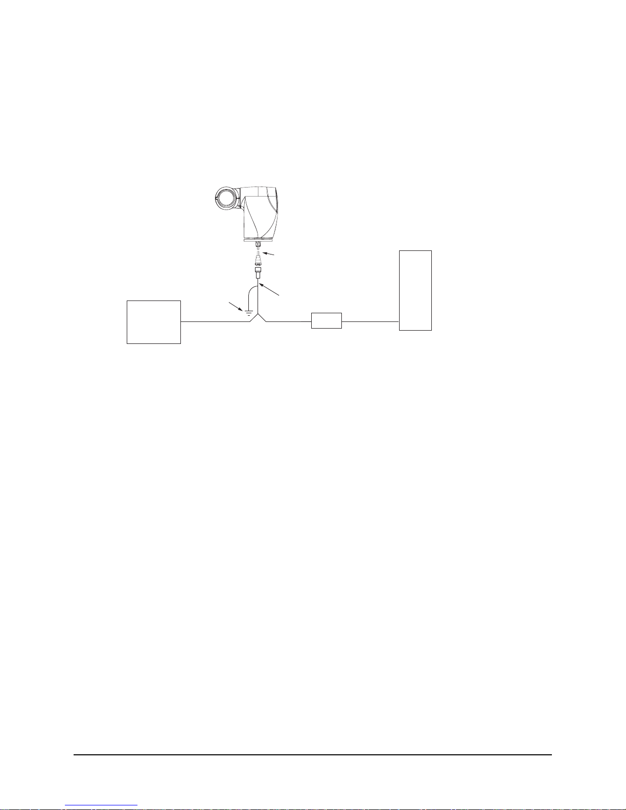
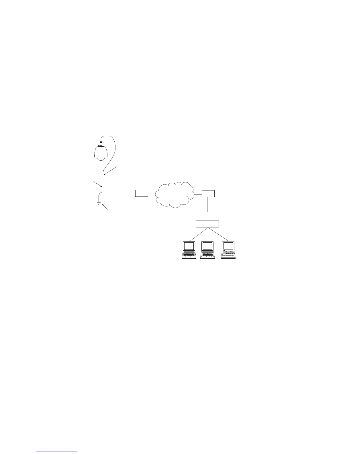
1.4 3960HD/3960SD/5970SD Interconnection Diagram
Figure 1 shows an interconnection diagram for the 3960HD/3960SD/ 5970HD series cameras.
NOTE: If your PC has a GigE network interface, you can bypass the switch and plug the camera system
RJ45 cable directly into the GigE port on your computer.
This diagram represents a typical installation. Each installation site will have its own unique requirements.
Default IP Address
192.168.2.150
Earth
Ground
Power
Power Cord
NOTE: Analog video, serial (RS232/RS422), and alarm connections are not shown for clarity
Properly secure the camera system
before the power is applied.
Pigtail Cable
System Cable
(CAT5e)
Switch
PC
.
Figure 1. Interconnection Diagram
.
6X-1090K6
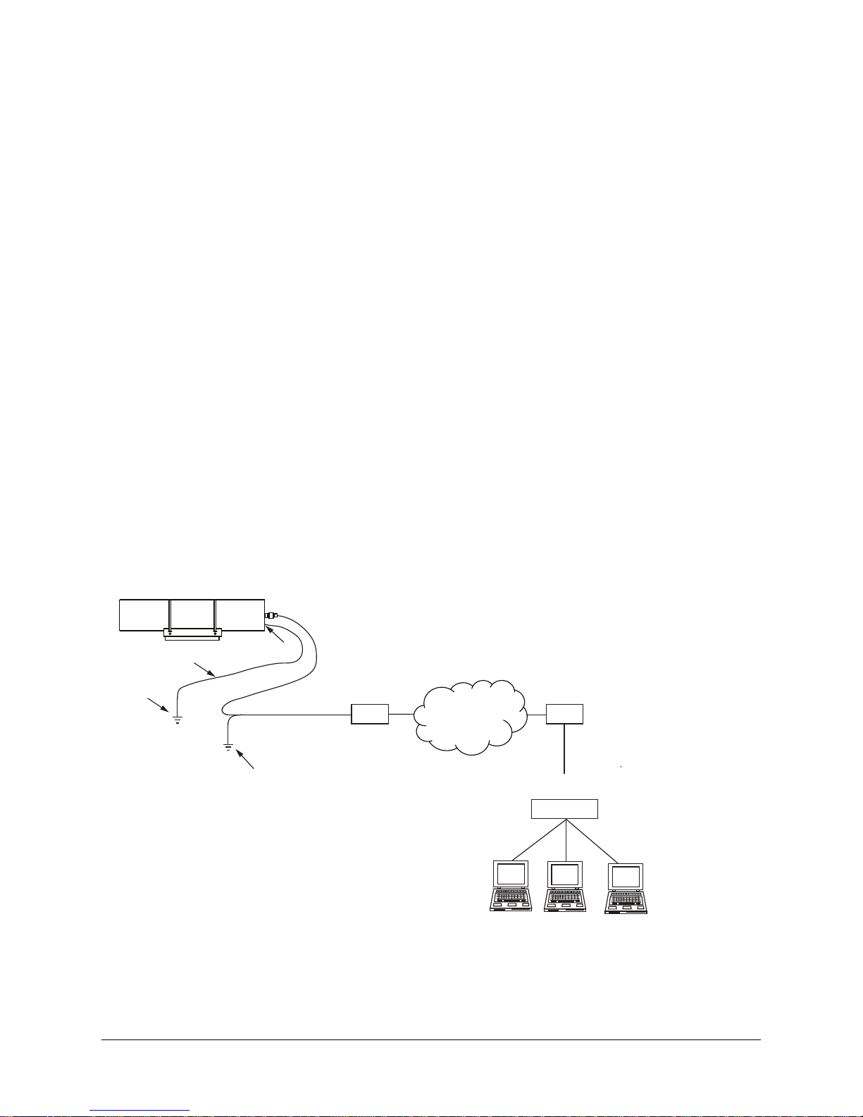
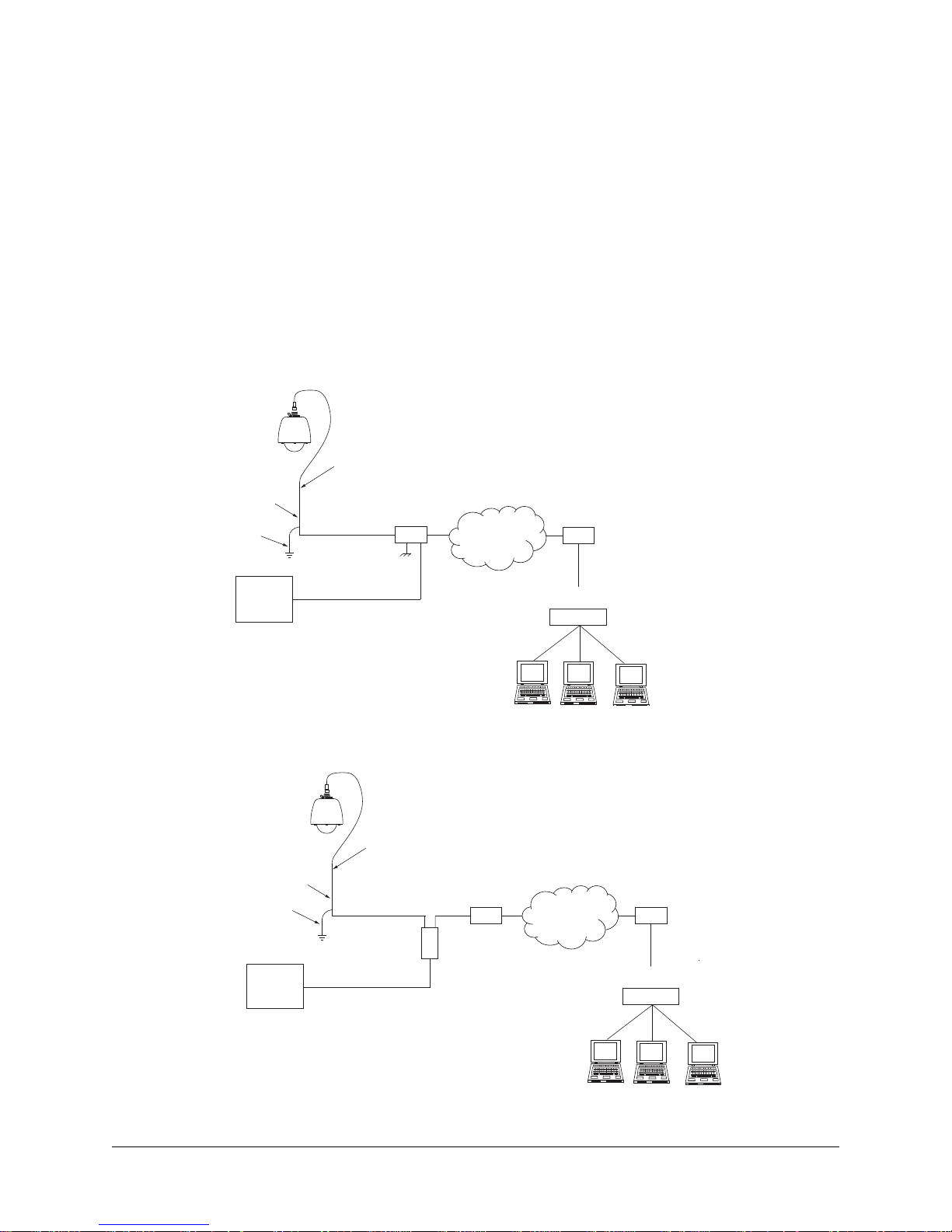
1.5 3930HD Interconnection Diagram
Figures 2 and 3 show interconnection diagrams for 3930HD:
• Figure 2 shows a setup of the camera system with PoE-enabled switch.
• Figure 3 shows a setup of the camera system using the PoE injector with non-PoE switch.
NOTE: If your PC has a GigE network interface, you can bypass the switch and plug the camera system
RJ45 cable directly into the GigE port on your computer.
These diagrams represent typical installations. Each installation site will have its own unique requirements.
Power over Ethernet (PoE)
The 3930
HD
camera system is compliant with the IEEE 802.3at standard. Power to the camera system is
supplied through the network cabling. Two types of PoE implementations are specied by the standard:
• Endspan PoE: Power is applied directly by the switch to the camera system. This method requires
the deployment of a PoE-enabled switch.
• Midspan PoE: Power is supplied by an injector placed between an existing non-PoE switch and the
camera system.
PoE injectors can be ordered from CohuHD. PoE injector is supplied with the HD15 option. Please refer to
the CohuHD web page in the 3930
HD
series specications section for ordering information. The PoE injector
selected for use with 3930HD must meet the following requirement:
• Be compatible with the IEEE 802.3at standard. For information on PoE injectors, refer to the website: www.ieee.li/pdf/viewgraphs/introduction_to_poe_ieee802.3af_802.3at.pdf.
Default IP Address
192.168.2.150
16 AWG Wire
Earth
Ground
Grounding Stud
Earth
Ground
Properly secure the camera system
before the power is applied.
System Cable
(CAT5e)
Router/PoE Switch
Router/Switch
WAN
LAN
Network
Switch
Figure 2. Interconnection Diagram with PoE-enabled switch
6X-1090K
7
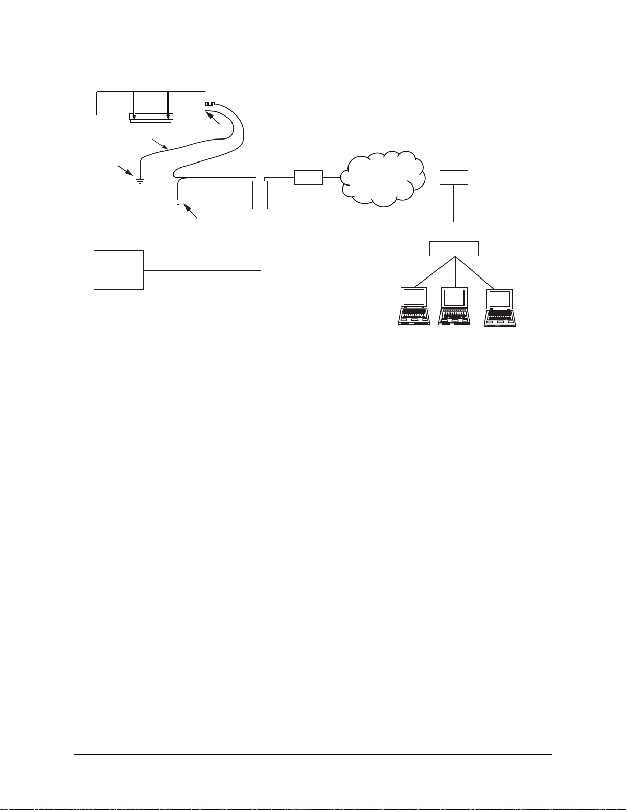
Default IP Address
192.168.2.150
16 AWG Wire
Earth
Ground
100-240 Vac
Power
Grounding Stud
PoE Injector
Earth
Ground
Power Cord
Properly secure the camera system
before the power is applied.
System Cable
(CAT5e)
Out
Router/
non-PoE Switch
In
Router/Switch
WAN
LAN
Network
Switch
Figure 3. Interconnection Diagram with non-PoE Switch
6X-1090K8
1.6 3920HD/3920SD Interconnection Diagram
Figures 4 and 5 show interconnection diagrams for the 3920HD/3920SD series cameras:
• Figure 4 shows a setup of the camera system using IP output.
• Figure 5 shows a setup of the camera system using analog and IP output.
NOTE: If your PC has a GigE network interface, you can bypass the switch and plug the camera system
RJ45 cable directly into the GigE port on your computer.
These diagrams represent typical installations. Each installation site will have its own unique requirements.
Properly secure the camera system
before the power is applied.
Default IP Address
192.168.2.150
System Cable
Cable Shield(s)
Power
Earth
Ground
CAT5e
Cable
Router/Switch
WAN
Router/Switch
LAN
Network
Switch
Power
Analog
Monitor
Figure 4. Interconnection Diagram, IP Output
Properly secure the camera system
Default IP Address
192.168.2.150
Cable Shield(s)
Earth
Ground
Coax Cable
before the power is applied.
System Cable
Router/Switch
CAT5e
Cable
Serial Cable
422
RS-232/422 Converter
232
Direct plug-in
to computer
serial port
WAN
Router/Switch
LAN
Network
Switch
Figure 5. Interconnection Diagram, Analog and IP Output
6X-1090K
9
1.7 3120HD/3720HD Interconnection Diagram
Figures 6, 7 and 8 show interconnection diagrams for the 3120HD and 3720HD series camera systems:
• Figure 6 shows a setup of the camera system using IP output.
• Figure 7 shows a setup of the camera system with PoE-enabled switch.
• Figure 8 shows a setup of the camera system using the PoE injector with non-PoE switch.
NOTE: If your PC has a GigE network interface, you can bypass the switch and plug the camera system
RJ45 cable directly into the GigE port on your computer.
These diagrams represent typical installations. Each installation site will have its own unique requirements.
Power
24 Vac ± 10%
@ 3 A min
Default IP Address
192.168.2.150
Cable Shield(s)
Properly secure the camera system
before the power is applied.
System Cable
Earth
Ground
CAT5e
Cable
Router/Switch
WAN
Router/Switch
LAN
Network
Switch
Figure 6. Interconnection Diagram, IP Output, 24 Vac
6X-1090K10
Power over Ethernet
The 3120HD and 3720
HD
camera systems are compliant with the IEEE 802.3at standard. Power to the cam-
era system is supplied through the network cabling. Two types of PoE implementations are specied by
the standard:
• Endspan PoE: Power is applied directly by the switch to the Camera. This method requires the
deployment of a PoE-enabled switch.
• Midspan PoE: ower is supplied by an injector placed between an existing non-PoE switch and the
Camera.
PoE injectors can be ordered from CohuHD. Please refer to the CohuHD web pages in the 3120HD or
HD
3720
Series specications sections for ordering information. The PoE injector selected for use must
meet the following requirement:
Be compatible with the IEEE 802.3at standard. For information on PoE injectors, refer to the website:
www.ieee.li/pdf/viewgraphs/introduction_to_poe_ieee802.3af_802.3at.pdf.
Default IP Address
192.168.2.150
Cable Shield(s)
Earth
Ground
Power
Properly secure the camera system
before the power is applied.
System Cable
CAT5e
Cable
Router/PoE Switch
WAN
Router/Switch
Network
Switch
Figure 7. Interconnection Diagram with PoE-enabled switch
Properly secure the camera system
Default IP Address
192.168.2.150
before the power is applied.
System Cable
LAN
Cable Shield(s)
Earth
Ground
Power
Figure 8. Interconnection Diagram with non-PoE Switch
6X-1090K
CAT5e
Cable
PoE Injector
Out
non-PoE Switch
In
Router/
WAN
Router/Switch
LAN
Network
Switch
11
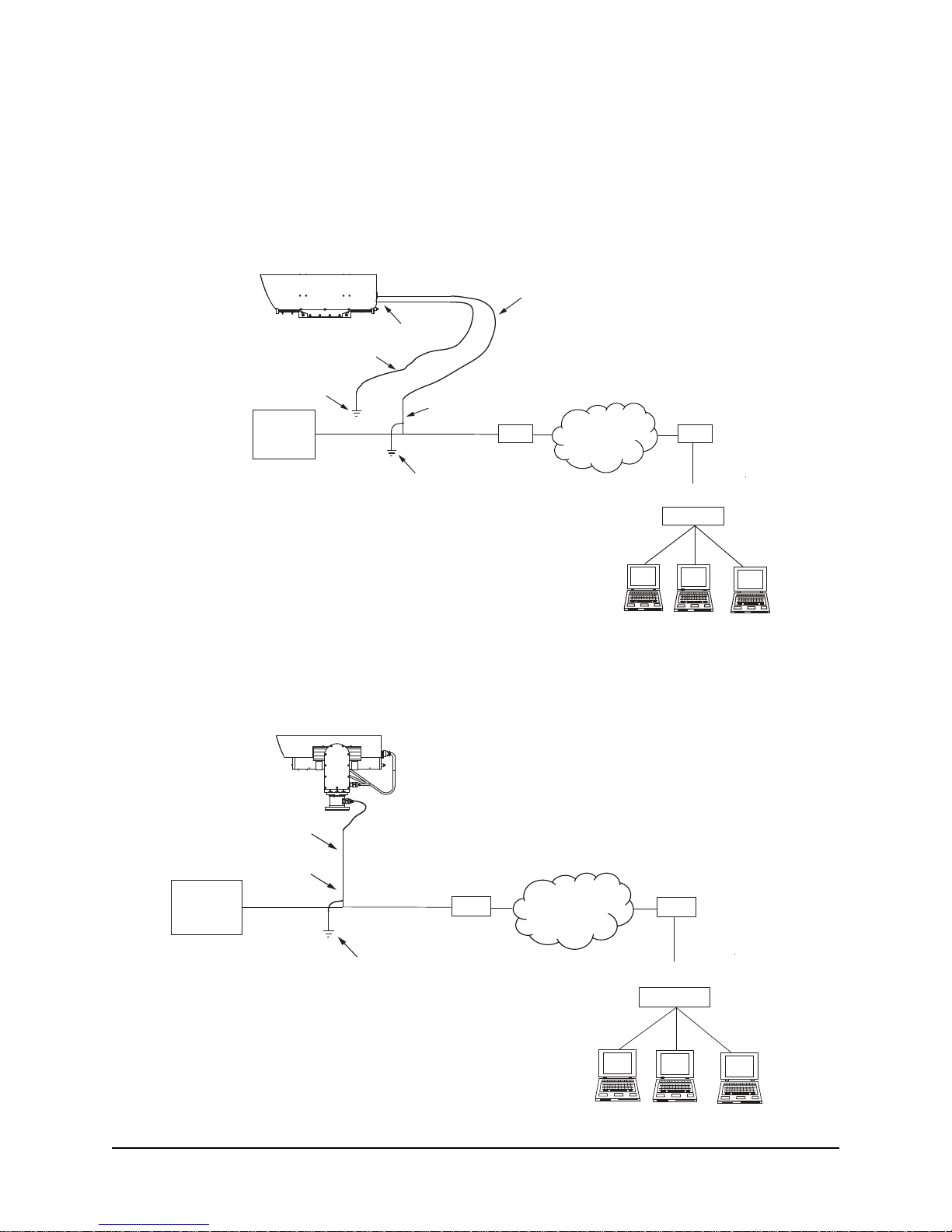
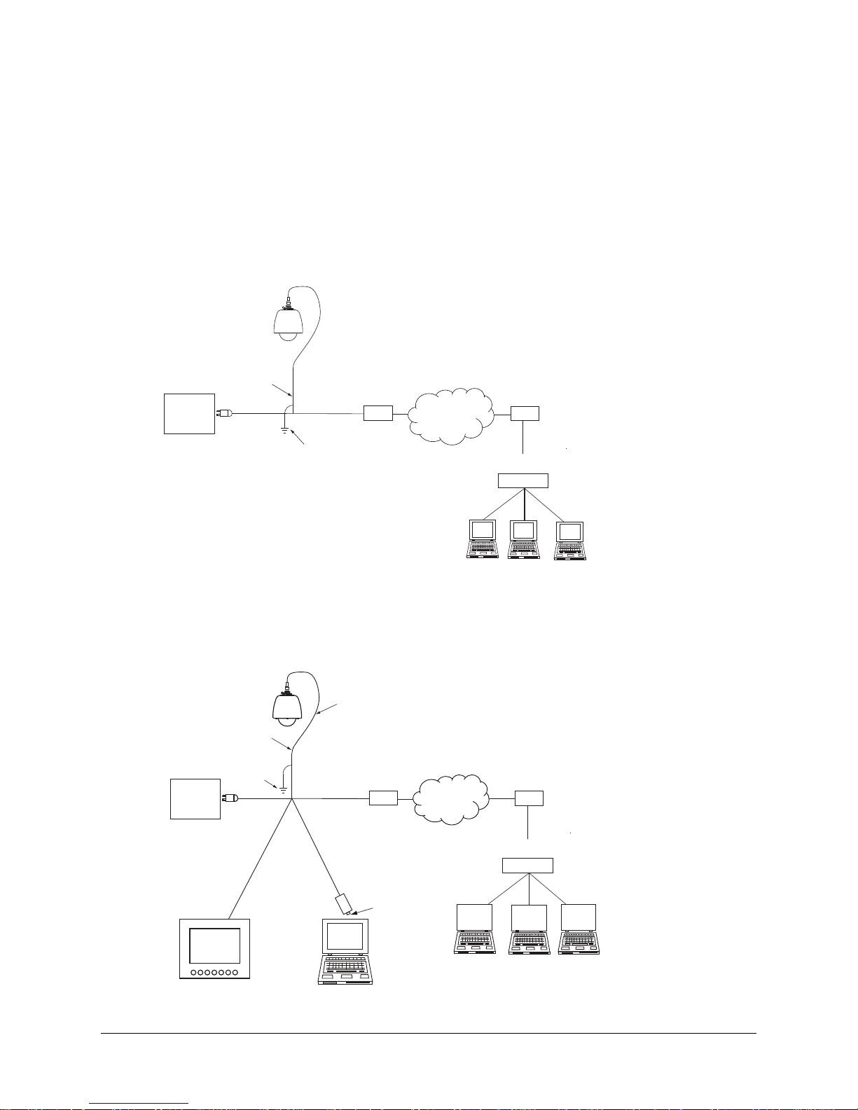
1.8 8800HD Interconnection Diagram
Network
Switch
Power
Router/Switch
CAT5e
Cable
Router/Switch
WAN
LAN
System Cable
Earth
Ground
Cable Shield(s)
Default IP Address
192.168.2.150
Properly secure the camera system
before the power is applied.
The gure below shows interconnection diagrams for the 8800
HD
series camera systems.
NOTE: If your PC has a GigE network interface, you can bypass the switch and plug the camera system
RJ45 cable directly into the GigE port on your computer.
These diagrams represent typical installations. Each installation site will have its own unique requirements.
Properly secure the camera system
before the power is applied.
Default IP Address
192.168.2.150
Power
16 AWG Wire
Earth
Ground
Grounding Screw
Cable Shield(s)
Earth
Ground
CAT5e
Cable
System Cable
Router/Switch
WAN
Router/Switch
LAN
Network
Switch
Figure 9. Interconnection Diagram. Standalone Camera System
Figure 10. Interconnection Diagram. Camera Positioner System
6X-1090K12

1.9 Assigning the Static IP Address
IMPORTANT: In order to make changes in network settings and install ActiveX® controls in the local ma-
chine the user must be logged in as Administrator. Please contact your local IT department if you do not
have Admin privileges.
Set your computer IP address to the same subnet as the camera system IP address.
• Go to Start > Control Panel > Network connections > Local Area Connection.
1. Local Area Connection dialog box will appear. Click the Properties button.
Click “Properties”
2. Y ou will see the Local Area Connections Properties dialog box. In the General tab, highlight
the Internet Protocol (TCP/IP) line. Click the Properties button.
General Tab
Highlight
“Internet Protocol (TCP/IP)”
Click “Properties”
6X-1090K
13
3. You will see the Internet Protocol (TCP/IP) dialog box. Select the Use the following IP address button in the General tab. Enter IP address: the IP address range is 192.168.2.1 through
192.168.2.254 except the IP address that already is used by the camera system. The subnet
mask must be 255.255.0.0. Click the OK button to close the Internet Protocol (TCP/IP).
General Tab
Select “Use the following IP address”
Enter an IP address which is not used
by the camera. The IP address range is
192.168.2.1 through 192.168.2.254
except 192.168.2.150*
Enter subnet mask:
255.255.0.0
Click “OK”
NOTE: * Since the subnet mask is 255.255.0.0 the IP address can be 192.168.0.1 through
192.168.255.254 except 192.168.2.150 (the default address that has been assigned to the camera).
4. Click the OK button to close the Local Area Connections Properties dialog box and click the
Close button to close the Local Area Connection dialog box.
Click “OK”
Click “Close”
6X-1090K14

2.0 Accessing the Camera Using the Helios Web Interface
The Helios Web Interface works with Internet Explorer (IE) 8 or 9. Microsoft ActiveX® is required to view
and control video in the Helios Web Interface.
MPORTANT: In order to make changes in network settings and install ActiveX® controls in the local machine the user must be logged in as Administrator. Please contact your local IT department if you do not
have Admin privileges.
Upon delivery, the rst time you access the camera system for starting a video stream take the following
steps:
• Log in as a local administrator on your computer.
• Start Microsoft Internet Explorer, version 8 or 9.
NOTE: You may need to set security level in IE and add the camera system as a trusted site in
order to run a video.
• Enter the camera IP address in the browser address box. The default address is
http://192.168.2.150.
• The camera will attempt to install an ActiveX control on your PC. Allow the camera to install ActiveX
Control by clicking on the prompt “This website wants to install the following add-on: CohuRTPControl.cab from CohuHD.” Click “Install this Add-on” from the submenu.
• Click Install in the Security Warning window box.
6X-1090K
15

• The Home page will be displayed.
• Press the Start Live Video button ( ) to start the video stream.
IMPORTANT:
Upon delivery, the rst time you access the camera you are logged in as an Admin and have unrestricted access to the camera’s conguration and operation. Authentication is turned off and admin-
istrator rights are granted without log in. For security reasons, it is recommended that authentication
be established promptly. See Section 2.2.1.6.
Password Protection
If the camera is password-protected, a dialog box to enter the user name and password will be displayed.
• Type the user name and password.
• Click the OK button.
Authentication
Four users’ accounts are dened in the Helios Web Interface to allow different levels of access. Those accounts are:
• Guest
• User
• Priv
• Admin
For more information see Sections 2.2.1.6 and 2.2.2.
6X-1090K16
Assigning the New Camera IP Address
No two devices on a single Ethernet network can have the same IP address. Use the following steps to
change a Camera IP address before a second camera is added to the subnet.
• Set your computer IP address to the same subnet as the Camera IP address.
IMPORTANT: In order to make changes in camera conguration the user must be logged in as Administra-
tor.
• Change the Camera address. The Camera address can be changed manually or through a Dy-
namic Host Conguration Protocol (DHCP) server. See Operation Manual 6X-1090.
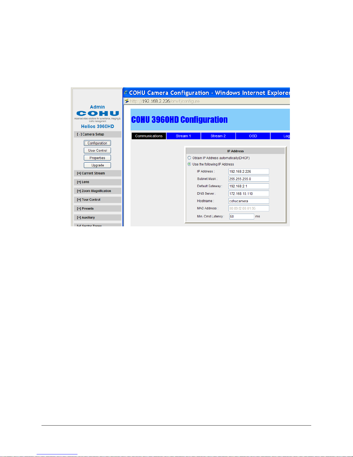
• Click the Camera Setup button.
• Click the Conguration button.
• Click the Communication tab.
The Communications tab is used for performing network conguration of the Camera. Changes to this tab
can only be made by the Admin account. Care must be taken when modifying parameters on this page as
the changes can make the camera inaccessible through the network. Consult with your network adminis-
trator before starting to assign new network settings to ensure that your camera won’t conict with other
devices.
• Write down the new camera address to make the camera easy to nd later. If the camera IP ad-
dress becomes lost, use the CohuONVIFDiscovery software to nd the camera on a network. The
software is available as a free download at http://www.CohuHD.com/content/downloads. Under
Software & Protocol Downloads > Setup Test Applications > Helios and 7500 Camera Series Discovery Tool click “download now”. See Section 4.6.
•
6X-1090K
17

Using the CohuONVIFDiscovery Software to Discover the Camera
• Download the software. See Section 4.5. Run the CohuONVIFDiscovery.exe le. Click to start it.
• The CohuONVIFDiscovery window will be displayed.
NOTE: Auto discovery feature uses network multicast packets and may not work through network routers.
• Click on the Start Discovery button. A list of cameras will be automatically displayed.
NOTE: Use the MAC Address or Model Index to identify CohuHD cameras. “00-09-f2” identies cameras
as CohuHD cameras. The MAC address of the camera is on the serial number label.
• Right click a camera entry. Click Copy IP to Clipboard.
NOTE: The CohuONVIFDiscovery software uses the ONVIF device discovery service. If the ONVIF discov-
ery service is disabled, the CohuONVIFDiscovery software will not nd the camera.
6X-1090K18
 Loading...