

COHU 7700-2 SERIES 1004 X 1004 Technical Reference Manual

7700-2 SERIES 1004 X 1004
PROGRESSIVE SCAN CAMERA
TECHNICAL REFERENCE MANUAL
CAMERA LINK
Model 7700-2 Camera
Shown with optional
1/4-20 mounting block
Technical Manual 6X-1029C
April 28, 2011
7700-2
Format 1/2-inch monochrome or color interline transfer CCD with square pixels
Pixels 1004 x 1004
Pixel Size 7.4 µm x 7.4 µm
Total Pixels 1,008,016
Output Characteristics 10-bit depth at 30 fps (full resolution)
Sync Internal crystal or external trigger
Shutter Control
Integration 1 to 65,000 frames (1 frame = 1/30 s) externally controlled
Sensitivity 4 lux (monochrome) with no shuttering (1/30 s) at 2450 K
Gamma 1.0 (xed)
Gain 0 to 34 dB, externally controlled
S/N Ratio 58 dB black, 48 dB white
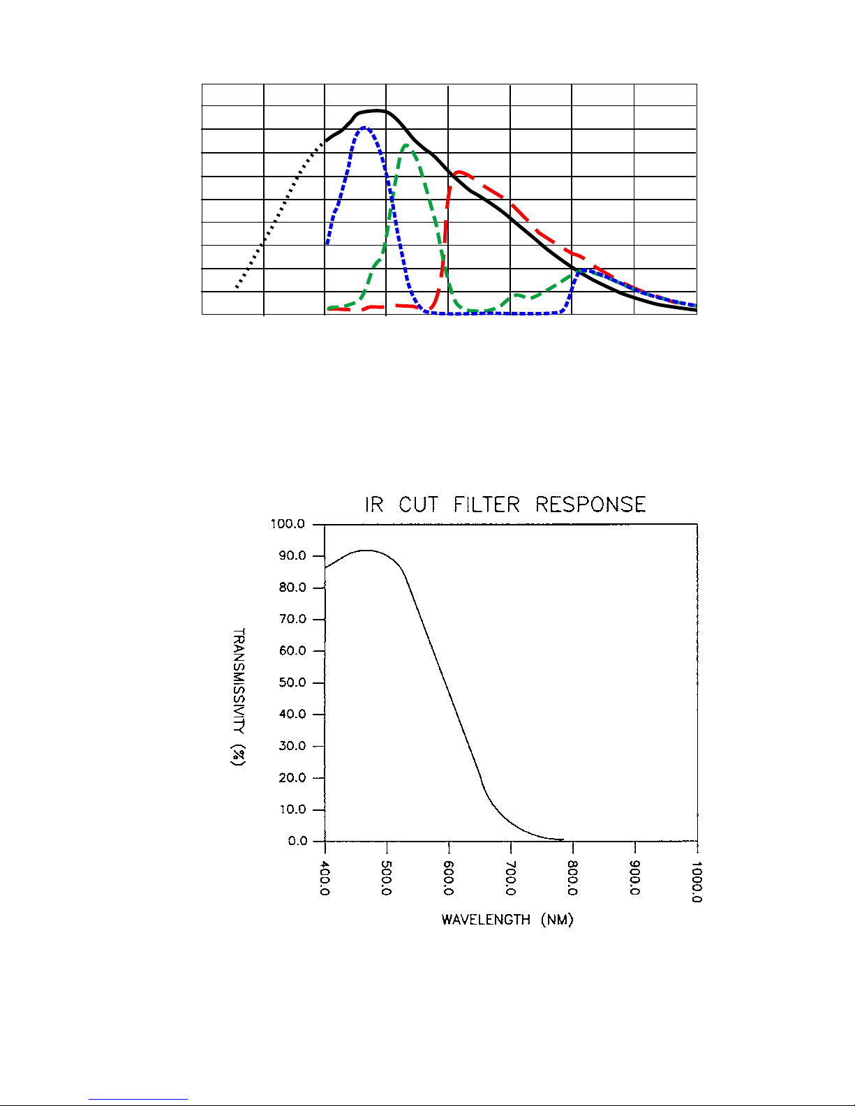
Spectral Response See gure 3 and gure 4 (color antialiasing lter)
Power Input 12±1.2 V dc
Power Consumption 390 mA (4.7 W)
Video Mode Free running, asynchronous
Snapshot Mode
Gain & Offset Control
Shutter Control
Size See gure 6
Weight 12 ounce (340 grams) less lens
Shock 15 g’s any axis, nonoperating per MIL-E-5400T
Operating Temperature -20 to 60 °C
Storage Temperature -30 to 70 °C
EMI Emissions FCC Class A
Lens Mount CS-mount, adjustable; 5 mm externer ring adapts to C-mount lenses
Camera Link Connector 26-pin MDR
Power Connector 3-pin Switchcraft TB3M (Cohu 1310356-003)
Reset Button Recessed rear panel (Hole for punch through of a paper clip)
Table 1. Model 7700-2 Specications
ELECTRICAL
• Fixed shutter: exposure time preset by camera setting
…Implicit lines: 1- 512 line interval in 10 steps
…Explicit lines: 1 - 65,000 line interval (line interval = 33.2 µs)
…Multiple frames: 1 - 65,000 frame intervals (frame rate = 33.3 µs)
• Pulse width shutter (Snapshot mode only): Exposure time determined by pulse width
of externally applied trigger
Modes of Operation
• Captures single image, 1/25,000 s to innity, initiated extrernally by applied trigger
pulse or by serial command. Exposure determined by pulse width of external trigger
• Full resolution: 10 bit depth at 30 fps
• Partial Readout: Dene single position for start of active readout in groups of four
lines
• Gain: Video gain amplier setting of 320 values
• Offset: Video black level setting of 1024 values
• Fixed: Exposure time preset by camera setting
• Variable: Software controlled 1/25,000 s to 870 s
MECHANICAL AND ENVIRONMENTAL
CAMERA INTERFACES
TECHNICAL REFERENCE
2
6X-1029C

TECHNICAL REFERENCE
7 7 × × — 2 0 0 0 / ××××
CAMERA
SERIES
VIDEO
FORMAT
1 - monochrome
2 - color
3 - monochrome
without sensor
glass (to obtain
UV response)
Figure 2. Model Number Interpretation Diagram
2 - 12 Vdc input to camera
rear panel (500 mA)
OUTPUT
OPTION
2 - camera link
POWER
CONFIGURATION
7700-2
LENS
OPTIONS
0000 - none
OPTION
000 - none
Cameras of the 7700-2 series provide
10-bit output in Camera Link format to an
external frame grabber.
Operating in progressive scan mode,
they use a 1/2-inch sensor to provide 1004
× 1004 pixel resolution at 30 frames per
second.
Higher frame rates can be established,
but with a corresponding reduction in the
number of lines available for readout.
The color version (7720-2) of this camera has an antialiasing lter in front of the
sensor. Sensor color ltering is the Bayer
pattern. All color processing is performed
by the external computer.
Operation in the UV region, (250-400nm)
requires a model 7732-2000 version of the
camera — which has the sensor faceplate
glass removed.
Setup and control of the camera is through
the rear-panel MDR connector operating via
asynchronous serial communications.
Offset, gain, and other functions are ad-
justable through this serial interface. Preset
camera congurations can be established to
allow for a rapid change of duty.
Inserting a paper clip through a hole in the
rear panel performs a hard reset. Also on the
rear panel is a green indicator that illuminates
when the 12 V dc power is applied.
6X-1029C
3
7700-2
TECHNICAL REFERENCE
.50
.45
.40
.35
.30
.25
.20
.15
.10
Absolute Quantum Efficiency
.05
.00
Note: Operation in the UV region requires a monochrome camera having had its sensor faceplate glass removed
Note: This cut l-
ter rolls off over-
all response for
color versions of
the camera from
about 500 nm out
beyond 700 nm
Mono
UV
R
Bu
Gn
300200
400
500 600
Wavelength (nm)
700
800
Figure 3. Sensor Response
(Cut lter effect on overall camera response not shown in this gure)
900
1000
Figure 4. Antialiasing Color Cut Filter
4
6X-1029C

TECHNICAL REFERENCE
7700-2
Table 2. Camera Mounted
Items Supplied
DESCRIPTION PART NUMBER
CS mount 8359208-001
C-mount adapter
(5 mm extender ring)
Setscrew, nylon
tipped, stainless, 4-40
x 5/32
Note: These items typically mount on the
camera when it is shipped (5 mm C-mount
adapter may be loose part)
2010695-001
2010258-005
Table 3. Type 8430-0
Accessory Kit
DESCRIPTION PART NUMBER
Power Plug, 3 socket
(Switchcraft TA3F)
Mounting Block (with
two 4-40 x 5/16 pan
head cross slotted
screws
Wrench, hex key, “L”
type, 0.050 across
ats (for lens mount
setscrew)
Note: If this optional accessory kit has been
ordered with the camera these items will be
contained in a separate packet included in
the shipping box
1310356-103
8428-8
9710010-009
6X-1029C
Figure 5. Front View
5
7700-2
TECHNICAL REFERENCE
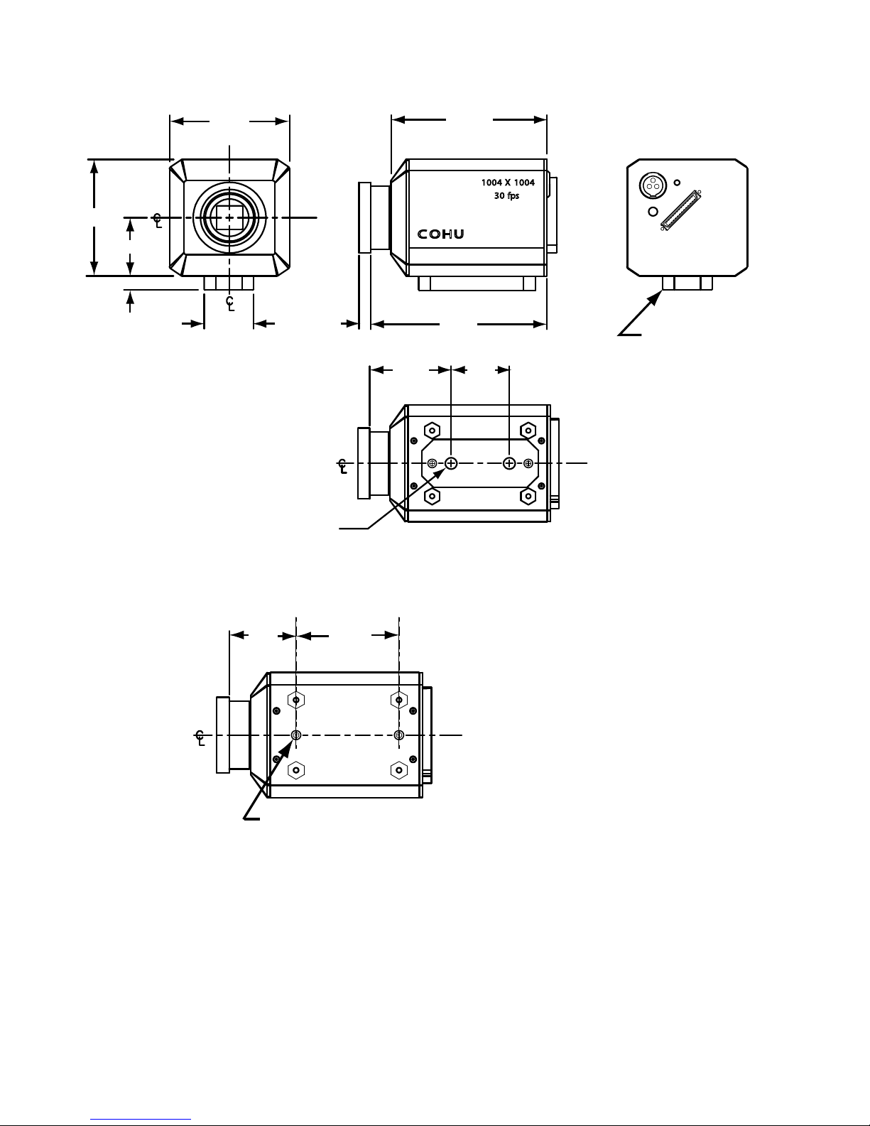
2.06
1.03
0.375
Unless otherwise noted
all dimensions in inches
1/4-20 Thread X 0.325 Deep
2.06
0.85
(2 Places)
0.197
(5 mm)
1.46
C OHU
3.10
2.76
1.00
100 4 X 1004
30 fps
12VDC
VID/CTL/PWR - I/0
Optional
Mounting Block
(P/N 8428-8)
See alternate drawing below
for mounting dimensions
of camera base without
the optional mounting block
(nominal)
4-40 Thd x 0.21 Deep
(2 Places)
1.6501.14
Mounting Dimensions Without
Optional Mounting Base
Figure 6. Dimensions
6
6X-1029C
TECHNICAL REFERENCE
7700-2
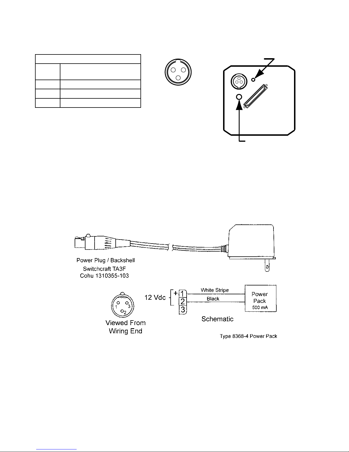
Power Connector Functions
PIN
NO.
1
2
3
Use minimum 500 mA supply
FUNCTION
+12 volt
ground
(no connection)
Figure 7. Power Input Features
1
Rear Panel View
3
2
Reset Access
12VDC
VID/CTL/PWR -I/0
Power Indicator
Figure 8. Type 8368-4 Power Pack (12 V dc 500 mA)
6X-1029C
7
 Loading...