

COHU 6110, 6112 Installation And Operation Manual
6110 SERIES
Megapixel IEEE-1394a Camera
INSTALLATION AND OPERATION MANUAL
Preliminary 3a 4-14-05
Figure 1. Monochrome Progressive Scan Camera
Lens Optional
Technical Manual 6X-1051
Phone: 858-277-6700
Fax: 858-277-0221
Cohu Electronics • 3912 Calle Fortunada • San Diego, CA 92123-1827
www.cohu-cameras.com
info@cohu.com
April 14, 2005
Preliminary 3a 4-14-05
6110 CAMERA
LIST OF SECTIONS
SECTION TITLE PAGE
1.0 GENERAL DESCRIPTION 3
1.1 Electrical C har acte r istics 3
1.2 Mechanical Characteristics 4
2.0 INSTALLATION 5
2.1 Equipment Supplied 7
2.2 Equipment Required but Not Supplied 7
2.3 Cabling Requirements 7
2.4 P ower Requirements 8
2.5 Mounting Requirements 8
2.6 Installation Procedure 10
3.0 Operation 14
3.1 Control Inputs & Outputs 14
3.2 Software Control 14
3.3 Frame Rates 14
3.4 Menu Items 14
3.5 "Camera" Drop-down Menu Items 14
3.6 "Mode" Menu Drop-down Items 19
3.7 "Rate" Drop-down Menu Items 19
3.8 "Cohu" D rop-down Menu Items 19
3.9 "Help" Drop-down Menu Items 19
3.10 Pop-up Viewer Windows 19
4.0 Handling Instructions 21
4.1 Unpacking & Receiving Instructions 21
4.2 Static Discharge Protections 22
4.3 Preparation for Shipment & Storage 24
INSTALLATION AND OPERATION
LIST OF FIGURES
FIG. TITLE PAGE
1 Monochrome Progressive Scan Camera 1
2 Sensor Optical Black Areas 3
3 Sensor Sensitivity Characteristic 3
4 Model Number Interpretation Diagram 5
5 Dimensions, Model 6112 6
6 Typical Installation Interconnections 8
7 Auxilia ry Input (RJ-45) Cable Diagram 9
8 Trigger Input Functional Diagram 11
9 Strobe Output Functional Diagram 11
10 Strobe Timing Reference 13
11 Strobe Output Field Reference 15
12 "Camera" Window (with typical selections) 18
13 "Camera" Drop-down Menu (Camera Stopped) 18
"Camera" Drop-down Menu with Select
14
Camera" Selected
"Camera" Drop-down Menu after "Init Camera"
15
Selected
16 "Camera Control" Window 20
17 "Check Link" Verify Window 22
18 "Maximum Speed" Window 22
19 "Problem Acquiring Image" Window 22
20 "Partial Scan Setup " Window 23
21 "C amera Identification" Window 23
22 "Strobe Setup" Windows 23
23 "Debug" Window 24
24 "Set Serial Number" Window 24
20
20
LIST OF TABLES
TABLE TIT LE PAGE
1Specifications 4
2 Key Points to Rem embe r 7
3 Items Supplied 10
4 Items Re quired but Not Suppli e d 10
5Cables Required 11
6 Drop-down Menu Items 12
7 "Camera" Drop-down Menu Items 17
2
6X-1050
Preliminary 3a 4-14-05
V
H
2 Pixels
40
2
8
Pin 1
Pin 11
OPTICAL BLACK POSITION
(Top View)
INSTALLATION AND OPERATION
1.0 GENERAL DESCRIPTION
This introduction briefly describes the overall
characteristics of the Model 6112 Camera
(figure 1) related to its installation and operation.
1.1 Electrical Characteristics
A model number interpretation diagram
appears in figure 4. That diagram shows the
various basic configurations of the Camera. Table
1 lists the specifications.
1.1.1 Sensor Characteristics
The sensor is a 1/2-inch (8 mm) 4:3 aspect
ratio package. It is a monochrome CCD interline
transfer progressive scan sensor. The glass
faceplate is 0.75 mm thick with a reflective index
of 1.5. There are 1360 horizontal and 1024
vertical active pixels. Pixels are square: 4.65 µm
x 4.64 µm.
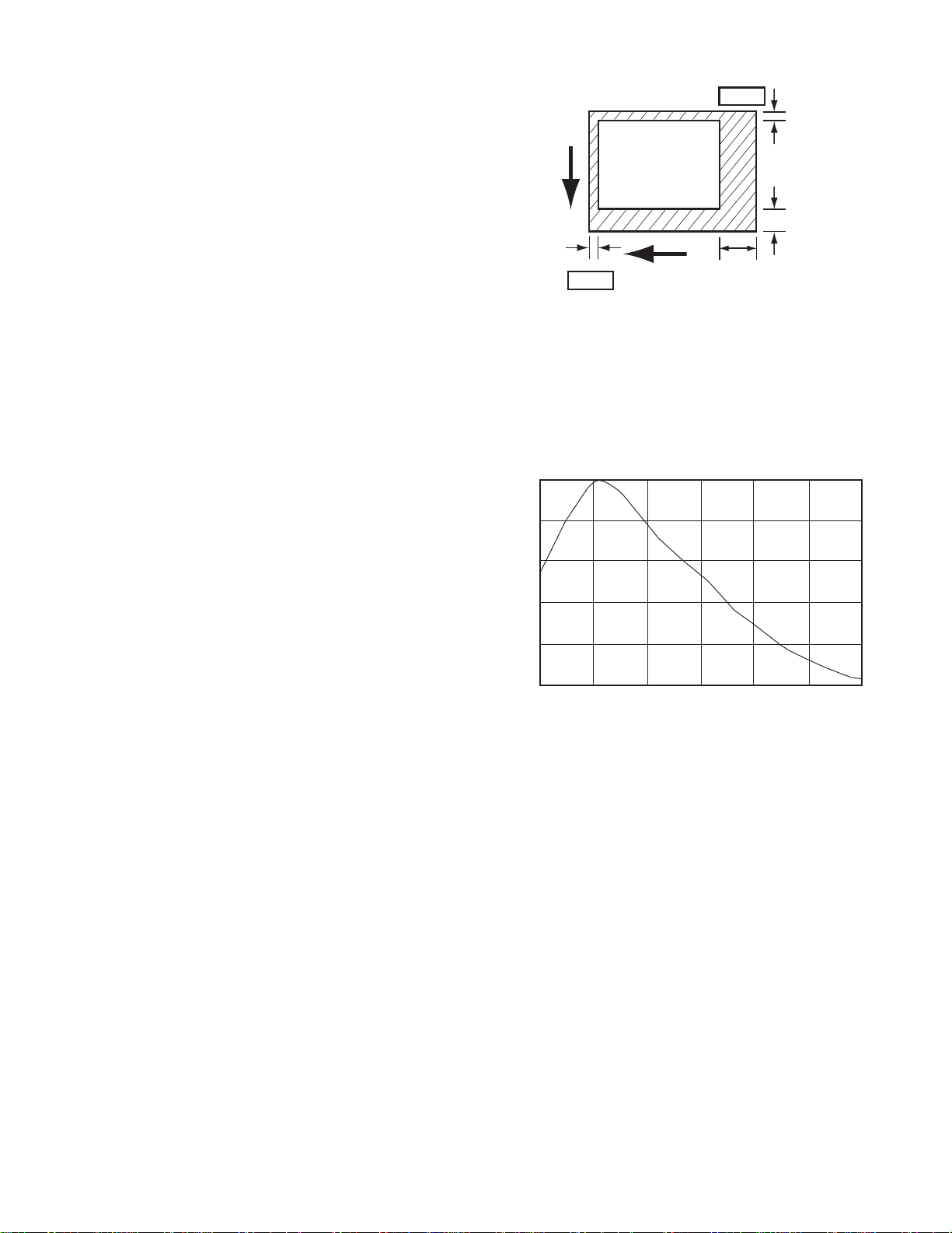
Figure 2 shows the optical black pixels
surrounding the active area. Figure 3 graphs the
spectral sensitivity of the sensor. Note that this
is the sensitivity curve of the sensor itself — not
including any lens or light source.
The Camera obtains enhanced sensitive and
low dark current through use of a Hole Accumulation Diode (HAD) sensor.
The sensor offers an electronic shutter with
variable charge store time so that a full frame
image can be obtained without a mechanical
shutter.
6110 CAMERA
Figure 2. Sensor Optical Black Areas
Sensor Sensitivity Characteristics
1
0.8
0.6
0.4
Relative Response
0.2
0
400
Figure 3. Sensor Sensitivity Characteristic
(excludes lens characteristics and light source characteristics)
500
600
700
Wavelength (nm)
800
900 1000
1.1.2 IEEE-1394a Connector (6-pin)
This connector is the six pin version of a
1394a connector. Two pins are used to carry
power to the camera. The camera derives operating power for video and processing control from
this connector. (Strobe circuits obtain dedicated
power from the RJ-45 connector.)
1.1.3 RJ-45 10 Wire Connector
Only seven of the 10 pins on this connector
are used: two for the trigger input to capture
scenes, four to strobe external scene lighting
circuits, and one to provide Vcc input for these
strobe circuits. These are opto-isolate circuit
functions. Power for these circuits is provided
6X-1050
from outside the camera to maintain complete
isolation from the other camera circuits.
1.2 Mechanical Characteristics
The 6110 has optical and mechanical interfaces identical to the Cohu model 2600 camera.
It can be mechanically substituted in place of a
2600 camera.
Dimensions are shown in figure 5. Note that
these dimensions do not include the adjustable
CS-mount. Also note that the base of the Camera
is dimensioned both with and without the mounting block. It can be removed if desired.
The CS-mount lens adapter threads into the
front of the housing. Adding the 5-mm extension
3

Preliminary 3a 4-14-05
6110 CAMERA
INSTALLATION AND OPERATION
Table 1. Specifications
ELECTRICAL
Sensor 1/2-inch format 4.65 micron x 4.65 micron
Active Pixels 1360 (H) x 1024 (V)
Resolution 1024 x 1024 tv lines
Sensitivity 3 lux, faceplate for full video, min gain, 1/30 sec exposure
Frame Rate 4 f/s at full resolution; 15 f/s at 256 lines/frame
Scanning 1280 (H) x 960 (V); Fewer than 960 lines can be selected
Trigger Input Optoisolated input for scene captureon RJ-45 auxiliary connector
Shutter Programmable 1/15 to 1/20,000 sec; up to 5 sec integration
Gain 0 to 30 dB manually programmable
S/N 60 dB
Gamma 1.0 fixed
ImageProcessing Mirror imaging and ROI
VideoOutput IEEE-1394A IIDC [D-cams] compliant [16 bit format]
Sync Internal; optional opto-isolated hardware trigger or software trigger
Control Outputs 4 optoisolated strobing outputs
C o ntr o ls G a i n, s hutte r, o ffs e t, fra m e rate , R O I win d o w vi a D-c a m re gi s te rs
Power, video and control 12 V dc (8 to 30 V dc IEEE-1394a compatible less than 3 watts
Power, auxiliary input Vcc required for opto-isolated strobe outputs
ME CHANICAL
Dimensions 1.53 high x 2.13 wide x 3.74 long in inches (39 x 54 x 95 mm)
Weight 1.0 lb (454 grams)
Connectors (2)
Temperature -5 to 60 °C (23 to 140 °F) operating; -20 to 70 °C (-4 to 158 °F) storage
Humidity <95 %, non-condensing
Shock 80 g (IEC 68)
Vibration (less lens) 8 g (IEC 68)
IEEE1394a (6 wire) video/control/power;
RJ45 (10 wire) Optoisolated trigger input; 4 discretes optoisolated outputs
ENVIRONMENTAL
ring (provided) allows C-mount lenses to be used
with the Camera.
Two connectors are located at the rear
panel. One is an IEEE-1394a six-pin connector
that carries video/control input power and the
other is an RJ-45 10-pin connector to support the
auxiliary functions of triggering and strobing. The
RJ-45 has power input on pin 7 to drive the
strobe stages. Triggering is directly driven by the
externally applied trigger signal.
The camera can be mounted in four ways:
1. By the lens
4
2. To the top of the case
3. Directly to the bottom of the case, and
4. To a removable mounting block on the bottom of
the case.
The top of the case has a single 1/4-20 hole
for mounting purposes.
The bottom of the case has a pair of
threaded 6-32 x 0.086-inch deep holes for direct
mounting or these mounting points can be used
6X-1050
Preliminary 3a 4-14-05
INSTALLATION AND OPERATION
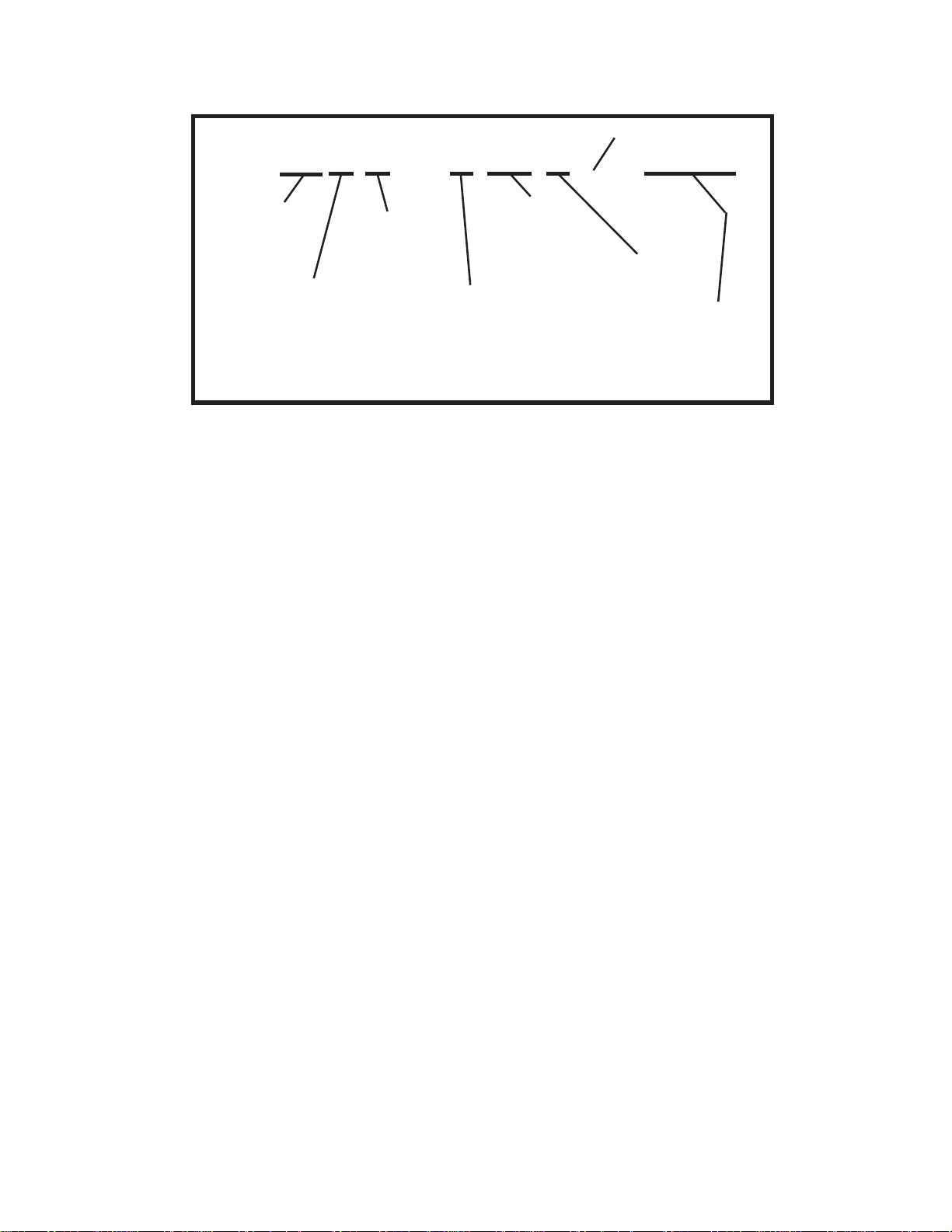
611 2 — 1 00 0 xxxx
Series
Monochrome
2k Camera
Sensor
1 1/2-inch format
monochrome
Figure 4. Model Number Interpretation Diagram
to attach the removable mounting block which
then provides two 1/4-20 mounting holes.
1.2.1 CS-mount or C-mount Lens
Use a manual-iris lens compatible with the
1/2-inch sensor in the camera. Either a CS-mount
lens or a C-mount lens can be used. Use of a Cmount lens will require that the 5-mm extender
supplied with the Camera be threaded onto the
C-mount lens before it is then threaded onto the
CS-mount adapter.
2.0 INSTALLATION
This section covers the general requirements of installing the camera including cabling
and power requirements. In addition to the actual
installation requirements, this section covers a
number of other items including static discharge
protection and proper shipping and handling of
the Camera. Refer to table 2 for a summary of
key points to remember about installing and
using the Camera.
Section 4 of this manual covers Receiving
Inspection, Static Precautions, and Return Shipment to the Factory.
2.1 Equipment Supplied
Table 3 lists the equipment supplied with the
basic camera model number. Other items may
be supplied if they wereordered with the camera.
Power
2 12 V dc over
IEEE-1394a
Camera
Output
1 IEEE-1394a
6110 CAMERA
Not
Assigned
Accessories
0 None
Lens
Option
Manual iris
CS- or C-mount
2.2 Equipment Required but Not Supplied
Table 4 is a list of equipment required to
make the camera operational in a minimum
configuration. Other items may be required
depending on the application.
2.3 Cabling Requirements
The rear panel provides two connectors for
interconnections with other equipment.
As a minimum, the IEEE-1394a connector
must be used. It provides several functions
including operating power to the camera, picture
data out to the viewing PC, and control functions
for the camera.
The RJ-45 connector offers two auxiliary
functions that may not be required. This is an
opto-isolated port and thus requires its own
supply power on pin 7. It has a trigger input to
capture a scene image and four programmable
strobe outputs to “fire” strobe lights during the
integration period of the sensor.
2.3.1 IEEE-1394a Cable
Installation cables for IEEE-1394a are best
obtained from a reliable cable manufacturer and
not built on-site. Use only a cable of the highest
quality. All six wires are required since the camera draws its operating power from this cable.
6X-1050
5

Preliminary 3a 4-14-05
6110 CAMERA
INSTALLATION AND OPERATION
6
Figure 5. Dimensions, Model 6112
6X-1050

Preliminary 3a 4-14-05
INSTALLATION AND OPERATION
6110 CAMERA
Table 2. Key Points to Remember
ITEM KEY POINTS
STROBE OUTPUTS
1 Using the strobe outp uts requires a cable with an RJ-45 connector
2 Using the strobe outputs requires that power be supplied to the RJ-45 connector
3 Strobe outputs must be current limited to pro tect the internal em itter follower drive transistor
4 Strobe outputs are optoisolated from other camera circuits
5 Start & stop times on the strobe setup window must be within the frame time being used
S hu tte rin g impac ts the s tro b e ti m e s tha t c a n b e s e t. W he n the s e n so r is b e i ng s hutte re d , th e inte g r a tio n
6
interval during which time the scene is obtained occurs during the last part of the vertical interval
TRIGGER INPUT
External triggering for scene capture can be implemented either through the software interface or by
7
ahardwire connection on the RJ-45 connector
8 Hardwire triggering does not use the Vcc power input on the RJ-45 rear panel connector
POWER INPUTS
9 P ower for camera video and control circuits is supplied via the 1394a cable (a 6-wire cable)
10 When strobe outputs are to be used, power must also be supplied to the RJ-45 auxiliary connector
OP E R A TIN G C O N S ID E RA T IO N S
11 Selecting some of the control functions requires stopping the camera (stop is equivalent to pause)
12 At full resolution, maximum frame rate is 4 frames per second
13 For setup and adjustm ent purposes, select the Draft mode for 12 frames per second operation
14 A tif or bmp image of the scene can be saved to an external hard drive or other device
For test bench cables, though, it is possible
to buy RJ-45 10-pin cable connectors and use a
punch-down tool to install the required wires onto
the connector.
2.3.2 RJ-45 Auxiliary Cable
Only seven of the 10 pins of this connector
are used. One pin is input power for the strobe
outputs, four are strobe output lines, and two
provide trigger input for scene capture. Depending on the length of this cable run and the noise
environment of the installation it may not require
overall shielding or shielding of the trigger lines.
Figure 7 is the wiring diagram for a cable showing overall shielding for longer runs.
2.4 Power Requirements
Operating power for the camera must be
supplied via the 1394a cable. Power for the
strobe outputs must be supplied to the RJ-45
connector if they are to be used.
6X-1050
2.4.1 Power Over 1394a
The IEEE-1394a specification provides for
devices to obtain operating power over a 1394a
cable (6-wire type). The 6100 makes use of this
feature so the device it is connected to must
provide this power. Powered 1394a sources
must be capable of supplying any voltage from 8
to 30 V dc.
The Camera requires 12 V dc from the
1394a cable at less than 3 watts
If the Camera is to be operated with Viewer
software running on a laptop computer it is likely
that this computer will have a 4-pin (non-powered) 1394a connector. In this case an external
power supply adaptor will be required to interconnect between the 4-pin 1394a connector on the
laptop and a 6-pin 1394a cable (powered type) —
which then provides this adapter voltage to the
Camera. These adapters are spcifically made for
1394a applications.
2.4.2 Strobe Power via RJ-45
If power is required to the RJ-45 auxiliary
connector, it is applied to pin 7. This power is
7

Preliminary 3a 4-14-05
6110 CAMERA
6-wire 1394a Cable
6110
Camera
IEEE-1394a
AUX RJ-45
7-wire Cable
Scene
Illumination
NOTE:
PC must be running appropriate software
to interface with camera. This can include the
Cohu 6110 GUI interface, third-party software
such as National Instruments Lab View, or software
written or modified for the specific application.
Trigger drives the cathode/anode of an optoisolator diode
in the camera
1394a Port
with
Power Out
INSTALLATION AND OPERATION
PC
PC MONITOR
Monitor
Cable
Auxiliary Interface
+
Trigger (scene capture)
-
+Vcc Out
Strobed Inputs
(emitter follower
Note: External emitter
resistors required
driven)
DRIVERS
Illumination
Outputs
(strobed)
Local
Site
Interface
Figure 6. Typical Installation Interconnections
labeled +Vcc on the illustrations because the
actual voltage applied depends on the circuit
externally connected to the strobe outputs. A
typical input range would be from 3.3 V dc to 15 V
dc.
The strobed outputs are common collector
(emitter follower) circuits. Each output is specified
to provide a maximum of 35 mA in continuous
operation. An external 100 ohm series resistor is
shown in figure 9 to protect the internal drive
transistor from an accidental short to ground. This
assumes a 5 V dc input for Vcc on pin 7.
2.5 Mounting Requirements
The dimensions shown in figure 5 related to
mounting the Camera. The Camera can be
mounted in four different mounting configurations:
1. By the lens (being careful to ensure that the
attached cables do not provide excessive pressure
on the camera)
2. By the single 1/4-20 threaded hole on the top of
the case
3. By the two 6-32-0.086 threaded holes on the
bottom of the case
4. By two 1/4-20 threaded holes on a mounting
adapter that can be installed on the bottom of
the case. The Camera is typically shipped with
this mounting block installed.
The following paragraphs describe some of
the features of the Camera related to the installation process.
2.6 Installation Procedure
Prior to installing the camera it may be
necessary to prepare an auxiliary interface if
the triggering and strobe lines on the RJ-45
connector are to be used. See figures 6 and 7.
The camera can only be operated by
Viewer software running on a PC interfaced via
a IEEE-1394a cable.
Installing the Camera is straightforward. It
is only necessary to mount the Camera to a
suitable base, install the lens, attach the
cable(s), apply power, and operate it using the
Viewer software.
8
6X-1050
 Loading...