

COHU 3950 SERIES iVIEW Installation And Operation Manual
3950 iVIEW
INSTALLATION AND OPERATION
COHU, INC. ELECTRONICS DIVISION
Installation and Operation Manual
.
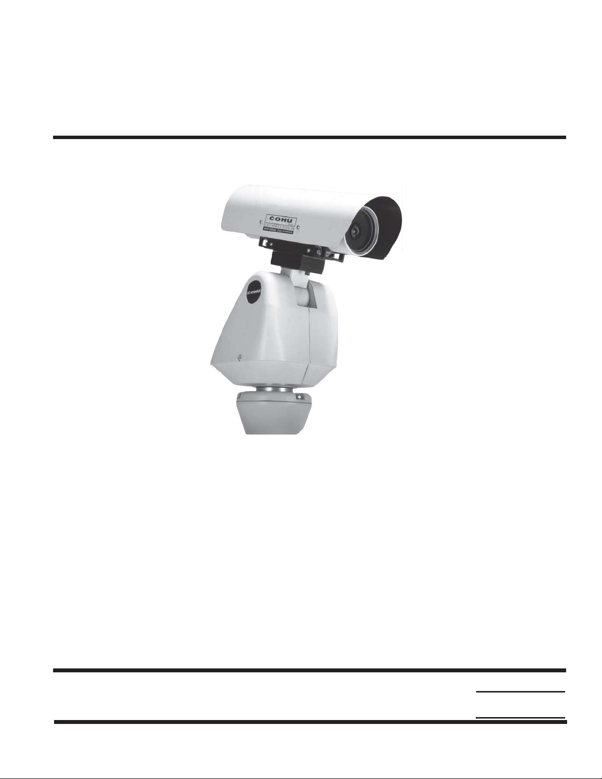
Figure 1. iView
3950 SERIES iVIEW
CAMERA/POSITIONER SYSTEM
Phone: 858-277-6700
FAX:
Cohu Electronics • 3912 Calle Fortunada • San Diego, CA 92123-1827
6X-1027a
858-277-0221
WEB: www.cohu-cameras.com
Email: info@cohu.com
August 12, 2005
COHU
Cohu Inc., Electronics Division
1
INSTALLATION AND OPERATION
SECTION TITLE PAGE
1.0 GENERAL DESCRIPTION 4
1.1 Elect rica l Characte r istics 4
FCC STATEMENTS
NOTE: This equipment has been
tested and found to comply with
the limits for a Class A Digital
Device, pursuant to Part 15 of
the FCC Rules. These limits are
designed to provide reasonable
protection against harmful interference when the equipment is
operated in a commercial environment. This equipment generates, uses, and can radiate radio frequency energy and, if not
installed and used in accordance
with the instruction manual, may
cause harmful interference to
radio communications. Operation of this equipment in a residential area is likely to cause
harmful interference in which
case the user will be required to
correct the interferecne at his
own expense.
1.2 Mechanical Characteristics 4
2.0 INSTALLATION 5
2.1 Unpacking and Receiving Inspection 6
2.2 Static Discharge Protection 6
2.3 Equipment Supplied 8
2.4 Equipment Required But Not Supplied 9
2.5 Power Requirements 11
2.6 Pedestal Mount Installation 11
2.7 Wall Mount Installation 12
2.8 Pole Mount Installation 12
2.9 Cabling Requirements 14
2.10 GUI Interface 18
2.11 Preparation for Shipment and Storage 23
3.0 OPERATION 23
3.1 Local Panel Control 23
3.2 Local Laptop PC Control 23
TABLE TIT LE PAGE
3950 iVIEW
LIST OF SECTIONS
LIST OF TABLES
1 Specifications 3
2 Equipme nt vs. Mo d el Number 5
3 Required Cable Characteristics 16
4 Connector Pin Functions 115 V ac or 230 V ac 20
5 Communications Settings 22
This device complies with part 15
of the FCC Rules. Operation is
subject to the following two conditions: (1) this device may not
cause harmful interference, and
(2) this device must accept any
interference received, including
interference that may cause undesired operation.
Changes or modifications to this
equipment not expressly approved
by Cohu Electronics could void
the users authority to operate the
equipment.
2
LIST OF FIGURES
FIGURE TITLE PAGE
1iView 1
2 M odel Number Interpretation 5
3 Typical Pedestal Mount Installation 7
4 Dimensions, Large Pedestal Base (LPED) 8
5 Typical Wall Mount Installation 9
6 Typical Pole Mount Installation 10
7 A rm and Adapter Plate Dimensions 11
8 P ole Mount Bracket Dimensions 12
9 Interconnection Diagram, iView to Local Control Panel 13
10 Interconnection Diagram, iView to Equipment Cabinet 14
11 Cable CA-297A (RS-422) Stripped Leads Version 15
12 Cable CA-297B (RS-422) BNC Plug & Power Plug 15
13 Cable CA-297C (RS-422) BNC Plug, Power Plug, & 232/422 Converter 17
14 Cable CA-297D Model 9300 Local Control Panel to iView 3955 18
15 Cable CTC-30, Test/Setup Wiring Diagram 19
16 Typical RS-232 to RS-422 Converter 19
17 Typical Win MPC Application 20
18 Typical Win MPC "Home" Screen 21
19 W in MPC Communications Functions Screen 22
20 Pedestal Test Stand 23
6X-1027a
3950 iVIEW
SP E CIF ICATION CHARACTERIS TIC
Resolution 470 horizontal tv lines
Day/Night Switchover Day (color) / night (mono), manual or auto
Sensitivity
Power Input
Power Connsumption 50 Watts with camera heaters on (camera and positioner)
Communications
Preset Speed >100°/second preset, at 0.5° accuracy
Title Generation 8 lines
Privacy Zones 8 programmable zones can be set for video blanking
Alarm Inputs 2 available
Environmental -40 to +55 °C
Pressurization Pressurized with dry nitrogen; IP Rating IP67, NEMA 4X
INSTALLATION AND OPERATION
Table 1. Specifications
Imager 1/4 inch color interline transfer CCD, progressive scan
Lens Integral 23X optical, 3.6 to 82.8 mm with 10X digital, auto/manual focus
Sync Phase adjust line lock
3.0 lux at 1/60 s (color day)
0.2 lux at 1/4 s (color day)
0.3 lux at 1/60 s (mono night)
0.02 lux 1/4 s (mono night)
115 V ac nominal (103.5 - 126.5), 60 Hz
230 V ac nominal (207 - 253), 50 Hz
24 V ac nominal (21.6 - 26.4), 60 Hz
Opto-isolated serial port RS-422 with digital position feedback;
RS-232 and RS-485 available
Protocol Non-propritary Cohu standard, others optional (see figure 2, protocols)
Firmware Stored in flash memory; upgrade via serial port
Pan/Tilt 360° continuous pan; +40º to -90º down
Presets 64
Tours 8, each of 32 presets with dwell timer per preset per tour
Sectors 16 in the horizontal plane
Humidity 100 percent, relative
Weight 28 lb (16 kg) approximate
6X-1027a
3

INSTALLATION AND OPERATION
3950 iVIEW
1.0 GENERAL DESCRIPTION
The 3950 iView series is a camera system that
integrates a high performance digital signal processing camera, pan-and-tilt Positioner, and control
receiver into one package.
Throughout this manual the entire assembly will
typically be referred to the “3950,” the “Positioner” or
the “iView.”
Specifications are cont ained in table 1. A model
number interpretation is provided in figure 2. This
can be used to interpret an existing model number.
WARNING
Some versions of this Positioner operate from
115 V ac or 230 V ac. Use all appropriate care
when installing and maintaining any equipment operating from these voltages.
1.1 ELECTRICAL CHARACTERISTICS
The camera uses digital signal processing (DSP).
It has an internal source ID generator. Integration
control plus a built-in video storage card provides full
color continuous video even at very low light levels.
The positioner speeds are variable with maximums of 100° per second in pan mode and 20° per
second in tilt while sustaining 90 mph winds. Pan
range is a continuous 360 degrees while the tilt
range is +40 to -90 degrees from the horizontal.
There are 64 preset positions with a preset accuracy of one-quarter degree. When responding to
standard pan-preset the Positioner can move with a
pan speed of 100° per second.
This camera/positioner will operate in temperature
ranges from -40° to +55° C and with winds of up to
90 mph. The enclosure protects against salt, grime,
dirt, and moisture.
Each iView “address” within a surveillance system
can be selected electronically from the Monitoring
Center. There are no mechanical dip switches to set
at the camera, and each unit responds to the central
command only if addressed. This provides greater
integration flexibility for the designer and more
dynamic camera control for the operator
1.1.1 Control Software
The Cohu camera system control software, is
designed to control the camera, camera DSP
functions, positioner, lens functions, as well those of
auxiliary equipment such as VCRs, screen splitters,
and monitor selection. The protocol and message
structure for camera is common for all cameras. No
proprietary protocol and message structure is used.
Three versions of control software are available:
Win MPC
Win MPC Graphical User Interface (GUI) software
is available for setting the address and performing
field tests for each iView . This can be obtained at no
cost from either the cohu-cameras.com web site or
by mail on floppy disk
Cams
The Cams protocol software is intended for
controlling multi-camera/positioner systems when
the Cohu MPC Master Control Panel is the central
control “intelligence” for the system. All control and
respond commands among the various equipment
in the system pass through the Master Control
Panel.
Net Cams
The Net Cams software is intended for controlling
multi-camera/positioner systems when a Windows
based PC is the central control “intelligence” for the
system. All control and respond commands among
the various equipment in the system pass through
the Net Cams Server.
The integrated receiver/driver, cont ained within the
iView, communicates using Cohu protocol messages to control all camera functions. All iView
functions are operable via RS-422 serial communications.
The Positioner is fully compatible with existing
Cohu controllers. In case of power failure, all 64
preset positions of all Positioners are stored in
nonvolatile memory .
4
1.2 MECHANICAL CHARACTERISTICS
Although the camera/positioner is a single mechanical assembly for installation purposes, it
actually consists of two subassemblies: (1) the
camera and (2) the positioner.
All camera circuits are contained within a sealed
and pressurized environmental housing having a
clear window at one end for viewing by the camera
6X-1027a

3950 iVIEW
CAMERA
SERIES
CONFIGURATION
3 - 230 Vac
4 - 24 Vac
5 - 115 Vac
POWER
INSTALLATION AND OPERATION
3 9 5 x — x 0 0 0 / ××××
VIDEO
FORMAT
3 - NTSC Phase Adj LL
7 - PAL Phase Adj LL
PROTOCOLS
1 - Cohu
Protocols of other manufacturers may also
be implemented by the camera/positioner
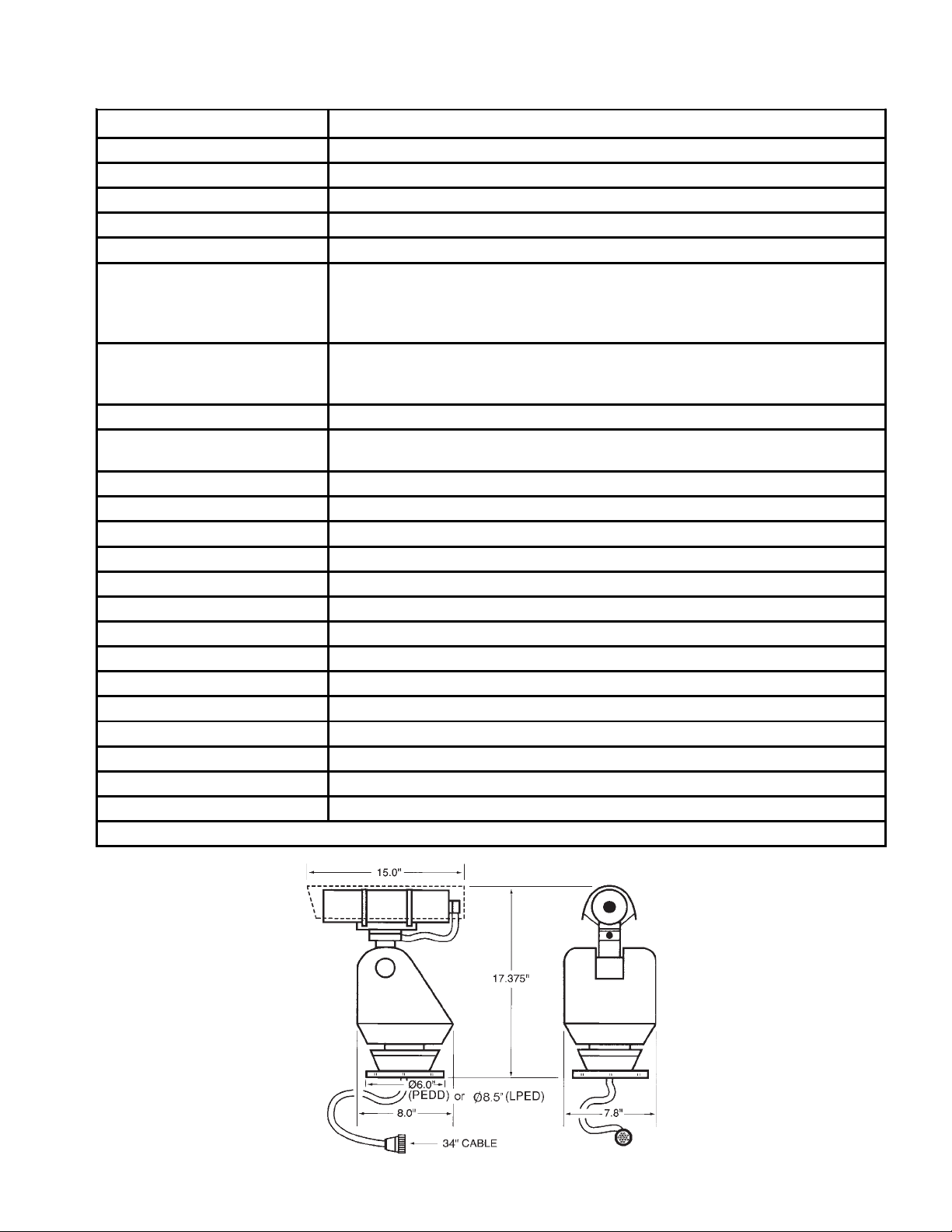
Figure 2. Model Number Interpretation
WALL
POLE
PEDD
LPED
(Wall Mount)
(Pole Mount)
(Pedestal, Small Base)
( Pedestal, Large Base)
UNASSIGNED
lens. This barrel is fully covered by a sun shield
spaced slightly away from the housing itself. This
minimizes heat buildup due to sunlight and also
serves to minimize sun flair by shading the lens at
some camera angles.
The pan/tilt positioner is a sealed unit intended for
outdoor use under rain, snow , and other typical
harsh weather conditions. Either a small (PEDD) or
larger (LPED) mounting base is installed to the pan/
tilt positioner depending on the model of iView
ordered.
A single multiconductor cable passes through the
base to provide for all signal and operating power
connections for both the pan/tilt unit and the camera.
This 34-inch cable has a 16 pin connector at the
other end for connection with the system cable
routed to its area.
Table 2. Equipment vs. Model Number
MOUNT
CONFIG.
Pedestal
Wall
CAMERA /
POSITIONER
ARM
•
•••
ADAPTER
PLATE
A Schrader valve on the rear panel of the camera
should be used to add dry nitrogen up to 5 psig
(pounds square inch gauge) to the barrel in the
event a “Low Pressure” message is received from
the control software.
2.0 INSTALLATION
An iView can typically mounted in any one of three
mechanical configurations depending on the mounting accessories supplied. This is determined by the
model number:
1. Pedestal Mount (PEDD and LPED models)
The simplest configuration. Only the iView is
supplied. It bolts directly onto the top of a site-
supplied pedestal having the
correct hole pattern or to an
adapter plate providing the proper
hole pattern. Figure 3 illustrates a
POLE
BRACKET
small diameter pedestal mount
base attached to the iView .
Figure 4 shows the larger LPED
base. It has two four-hole patterns on it. Depending on the
model of iView ordered one of
these two plates will be attached.
Pole
NOTE: Dot ( • ) designates items supplied for each mounting configuration.
••••
6X-1027a
5

INSTALLATION AND OPERATION
3950 iVIEW
2. Wall Mount (WALL model)
This mounting arrangement requires an arm that
bolts to the wall and an adapter plate between the
arm and the bottom of the Positioner. The arm is
typically supplied with this adapter plate already
installed.
3. Pole Mount (POLE model)
This mounting arrangement is similar to the Wall
Mount -- except that the mounting arm attaches to a
bracket fastened to a pole instead of directly bolting
to a wall.
Table 2 summarizes the major items supplied for
each of these three installation methods. Each of
these installations will be expanded upon in a later
sections.
2.1 UNPACKING AND RECEIVING INSPECTION
This item was thoroughly tested and carefully
packed in the factory. Upon acceptance by the
carrier, they assume responsibility for its safe arrival.
Should you receive this item in a damaged condition,
apparent or concealed, a claim for damage must be
made to the carrier.
in the event that an open unit were available, the
following precautions should be followed:
CAUTION
This Positioner/Camera contains sensitive devices
that can be damaged by static discharge. Use appropriate static control methods when working inside either the Positioner or Camera.
Components used in modern electronic equipment, especially solid state devices, are susceptible
to damage from static discharge. The relative
susceptibility to damage for semiconductors varies
from low with TTL to high with CMOS. Most other
semiconductors fall between TTL and CMOS in
susceptibility to static discharge. As a minimum,
therefore, observe the following practices when
working inside this or any other electronic equipment:
1. Use conductive sheet stock on the work bench
surface.
2. Connect the sheet stock to ground through an 1
megohm or greater value resistor.
To return the product to the factory for service,
please contact the Customer Service Department
for a Return Authorization Number.“
If a visual inspection shows damage upon receipt
of this shipment, it must be noted on the freight bill
or express receipt and the notation signed by the
carrier's agent. Failure to do this can result in the
carrier refusing to honor the claim.“
When the damage is not apparent until the unit is
unpacked, a claim for concealed damage must be
made. Make a mail or phone request to the carrier
for inspection immediately upon discovery of the
concealed damage. Keep all cartons and packing
materials.
Since shipping damage is the carrier's responsibility , the carrier will furnish you with an inspection
report and the necessary forms for filing the concealed-damage claim
2.2 STATIC DISCHARGE PROTECTION
Procedures in this manual do not require entry
into the housing of the positioner/camera. However
6
3. Use a wrist strap connected to ground through an 1
megohm or greater value resistor when working at
the bench.
4. Maintain relative humidity of the room above 30
percent. This may require a room humidifier .
Working on circuits with relative humidity below 30
percent requires extraordinary procedures not
listed here.
5. Use antistatic bags to store and transport an
exposes chassis, circuit boards, and components.
Use new antistatic bags. Old, used bags loose
their static protection properties.
This list serves as a reminder of the minimum
acceptable practices. Be sure that all static discharge devices at the work bench are properly
installed and maintained.“ S tandard grounding mat s
and wrist straps purchased for use at work benches
are supplied with leads having current limiting
resistors for safety. Never substitute with a grounding lead not having the resistor.
6X-1027a
3950 iVIEW
Positioner with 34-inch
“pigtail” and connector
INSTALLATION AND OPERATION
Positioner Small
Pedestal Baseplate
(PEDD) Dimensions
Base is permanently
attached to the iView
Dimensions of
Large Pedestal
Base (LPED) are
shown in fig. 4
TO
POSITIONER
CONNECT
AND
PLACE
INSIDE
THROUGH
CONDUIT
TO
CONTROL
EQUIPMENT
6X-1027a
CONDUIT
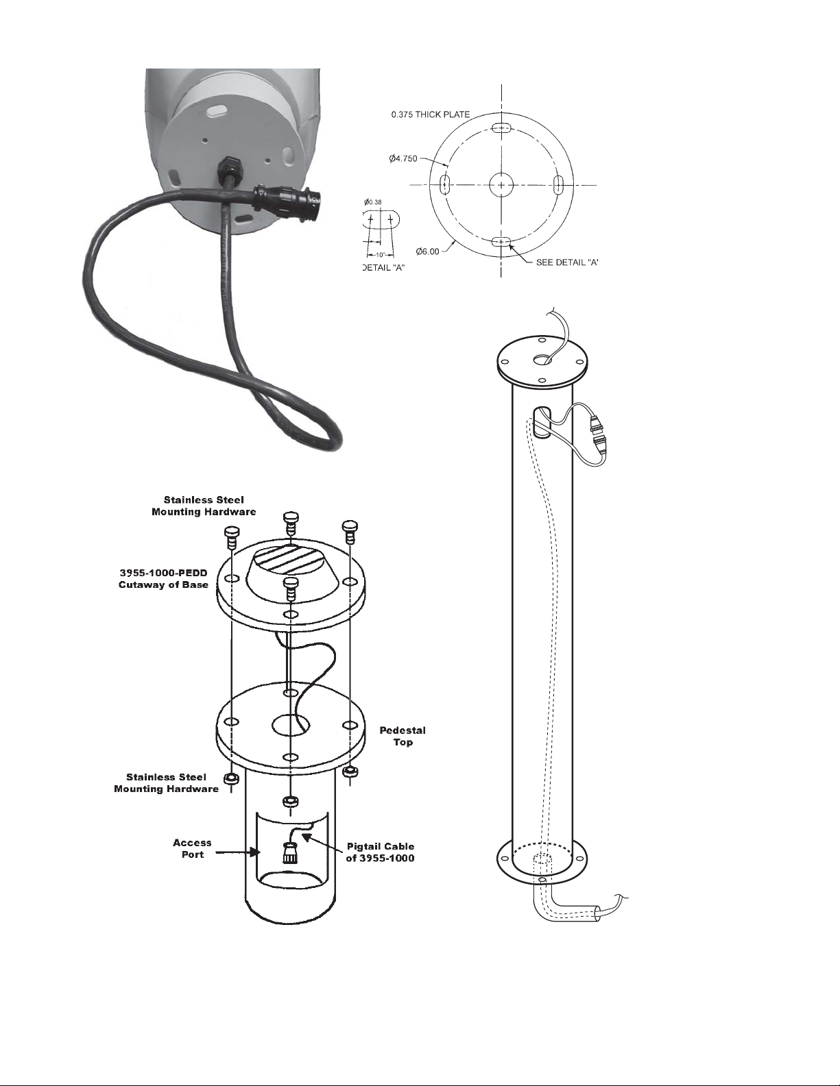
Figure 3. Typical Pedestal Mount Installation
7
INSTALLATION AND OPERATION
3950 iVIEW
Dimensions of Small Pedestal Base (PEDD) are shown in fig. 3
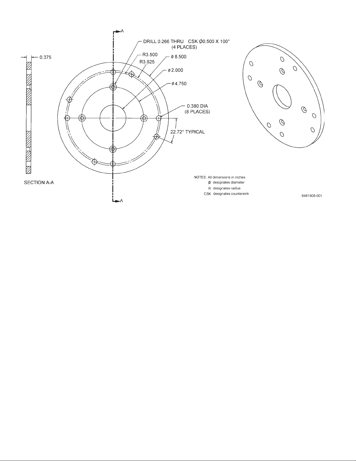
Figure 4. Dimensions, Large Pedestal Base (LPED)
2.3 EQUIPMENT SUPPLIED
Depending on the mounting configuration, several
variations of equipment can be supplied. See table 2
for a list of the basic differences between models as
related to mounting.
PEDD (Small Pedestal Base). See figure 3.
Pedestal mounting is the most basic of the three
mounting arrangements. Taller pedestals should
have an access plate near the top so that a strain
relief can secure the cable assembly in place. This
not only prevents the weight of the cable from pulling
on the connector but it is also a good general practice with all cable runs.
LPED (Large Pedestal Base) See figure 4.
The Large Pedestal Base option (figure 4) provides an 8.5-inch diameter base plate having two
four-hole patterns for mounting to various pole and
arm platforms currently installed at many locations.
One hole pattern is on a 7.00-inch diameter with
the four holes spaced 90 degrees apart.
8
Base is permanently attached to the iView
Farther out from that pattern is a 7.25-inch diameter pattern displaced by 22.720 degrees from the
first pattern. This pattern also consisting of four
holes spaced 90 degrees apart.
All eight of these mounting holes are of 0.380inch diameter. Up to 3/8-inch mounting hardware
can be used. Stainless steel hardware should be
used.
WALL (Wall Mount). See figure 5.
With a wall mount, the Pedestal bolts to the end of
an arm which is attached to a wall. Figure 6 gives
dimensions of the arm and adapter plate. This arm
is typically shipped with the adapter bracket attached. This wall must not only have four mounting
bolts but also a hole centered between these bolts
through which the cables must pass. A weather-tight
gasket should be used between the arm and wall.
Since the Positioner pigtail cable is about 34 inches
long it is likely that the connectors will be behind or
inside the wall or junction box in that area.
6X-1027a
 Loading...