

COHU 3940 IP i-Dome, 3944-590 Series, 3945-590 Series Installation Manual
3940 IP i-Dome
INSTALLATION
COHU, INC. ELECTRONICS DIVISION
Installation Manual
CE
FCC
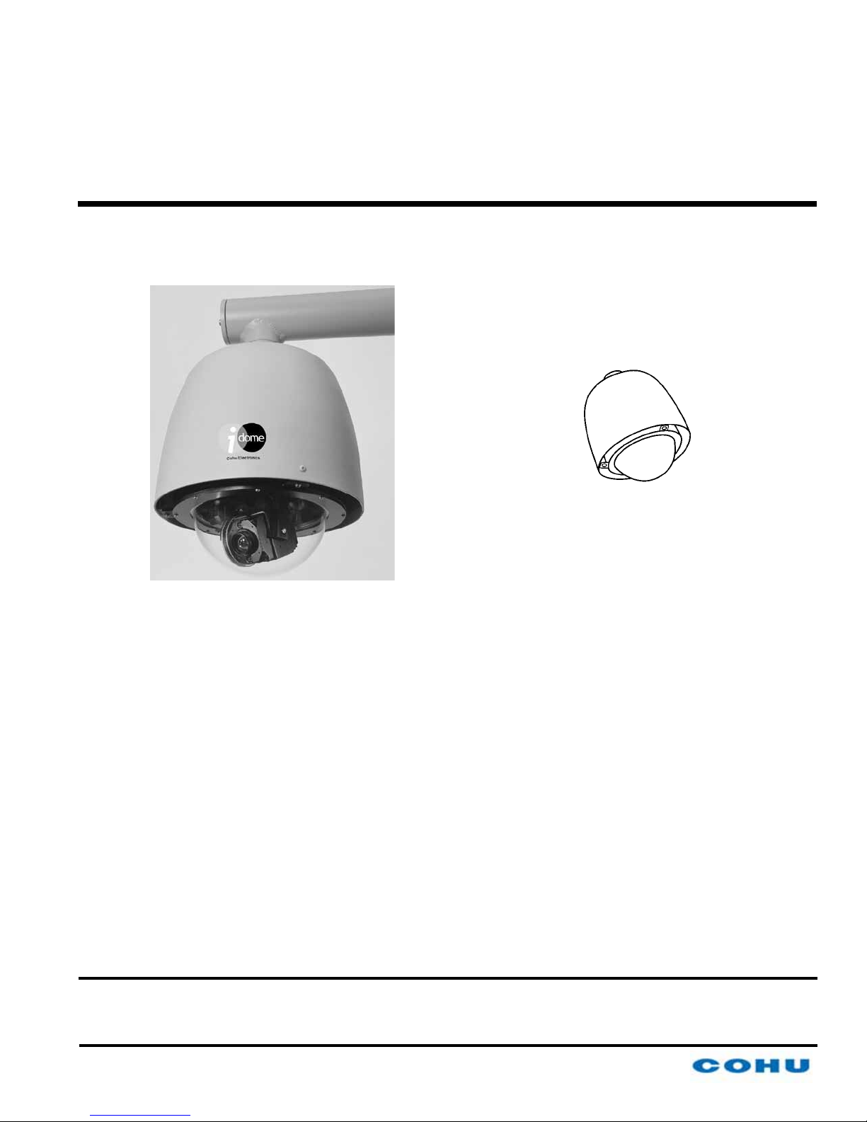
Figure 1. Model 394x-590x
Ethernet iDome
3940 IP iDome
CAMERA/POSITIONER SYSTEM
Technical Manual 6X-1070D
www.cohu-cameras.com/content/contactus
6X-1070D
June 28, 2012
www.cohu-cameras.com
info@cohu.com
1
INSTALLATION
3940 IP iDome
Refer to table 9 at the rear of this
manual for camera specications
Camera Software Support
Controlling this camera and viewing its video requires
software running on a PC. Currently, two options are
available:
1. For operation of the camera during installation and
setup, download WinMPC.Net from the Cohu website. This
software both controls the camera and views its video.
2. For the day-to-day operating software download the
SDK (Software Development Kit) from the Cohu website. A
programmer will then use this SDK to write the operating
software for the camera.
A third software download is available to update
rmware in the camera. This download will include DOS
upload /burn software and the actual rmware updates
themselves.
cohu-cameras.com
FCC STATEMENTS
NOTE: This equipment has been tested and found to comply with
the limits for a Class A Digital Device, pursuant to Part 15 of the
FCC Rules. These limits are designed to provide reasonable
protection against harmful interference when the equipment is
operated in a commercial environment. This equipment generates, uses, and can radiate radio frequency energy and, if not
installed and used in accordance with the instruction manual, may
cause harmful interference to radio communications. Operation
of this equipment in a residential area is likely to cause harmful
interference in which case the user will be required to correct the
interference at his own expense.
This device complies with part 15 of
the FCC Rules. Operation is subject
to the following two conditions: (1) this
device may not cause harmful interference, and (2) this device must accept
any interference received, including
interference that may cause undesired
operation.
Changes or modications to this equipment not expressly approved by Cohu
Electronics could void the users authority to operate the equipment.
FCC, 15B, Class A Ac Power Line Conducted Emissions
FCC, 15B, Class A Radiated Radiofrequency Emissions
EN 55022, Class A Power Line Coducted Emissions
EN 61000-6-3, Class A Signal Control dc Input/dc Output
Conducted Emissions
EN 55022, Class A Radiated Radiofrequency Emissions
2
EMI/EMC TESTS COMPLETED
IEC 61000-4-2, A1 + A2 Electrostatic Discharge Immunity
IEC 61000-4-3 Radiated RF Field Immunity
IEC 61000-4-4 EFT / Burst Immunity
IEC 61000-4-5 Lightning Surge Immunity
IEC 61000-4-6 RF Common Mode Immunity
6X-1070D

3940 IP i-Dome
1.0 GENERAL DESCRIPTION
The 3940 IP iDome is an integrated camera/positioner unit that combines a high performance digital
signal processing camera, pan-and-tilt, and control
receiver for communications into one integrated
package (gure 1). A 35x lens is provided.
It communicates with Ethernet TDP packets and
supplies video via Ethernet UDP packets.
An IP dome is congured to connect to a hub,
switch, or router. Connecting it directly to the NIC
(Network Interface Card) in a computer will require
use of a crossover cable or crossover adapter.
Throughout this manual the entire assembly will
typically be referred to as the “iDome” or just the
“Dome.”
Specications are contained in table 9 at the
back of this manual. A model number interpretation
diagram is provided in gure 2. This diagram can be
used to interpret an existing model number.
1.1 ELECTRICAL CHARACTERISTICS
The camera uses digital signal processing. It has
an internal source ID generator. Integration control
plus a built-in video storage card provides full color
continuous video even at very low light levels.
INSTALLATION
Up to 64 pre selected scene locations can
stored for later access These Preset locations
are available for use with the Tour functions. All 64
preset positions are stored in nonvolatile memory
to preserve them in the event of a power failure.
Each iDome “address” within a surveillance
system can be selected electronically from the
Monitoring Center. There are no mechanical dip
switches to set at the camera, and each unit responds to the central command only if addressed.
This provides greater integration exibility for the
designer and more dynamic camera control for the
operator.
Privacy zones can be set up using polygon
shaped windows drawn with the Viewer/GUI software. These blanking windows are generated electronically within the digital signal processing (DSP)
and provide positive control of such areas.
Electronic image stabilization (EIS) is a standard feature for the camera module used in this
dome. This EIS feature can be set to either 5 or 16
hertz to minimize the effects of slight vibrations on
a Dome in certain mounting situations — such as
when it is mounted on a tall pole.
1.2 SOFTWARE DOWNLOADS
The iDome speeds are variable with maximums
of 250° per second for pan and tilt. Pan range is a
continuous 360 degrees while the tilt range is 0 to 90
degrees from the horizontal with auto-ip at the 90°
point. There are 64 preset positions with a preset accuracy of 0.1 degree. When responding to standard
pan-preset or manual control, the iDome can move
with a pan speed of 250° per second.
This iDome will operate in temperature ranges
from -34° to +50° C and with winds of up to 90 mph.
The enclosure protects against salt, grime, dirt, and
moisture.
The integrated receiver/driver, contained within
the iDome, communicates using Cohu protocol
messages. These messages control camera DSP
functions and also the pan, tilt, zoom functions of
the positioner. All iDome functions are operable via
Ethernet serial communications.
6X-1070D
This camera is intended for computer control
and that computer must be running control and
viewing software dedicated to this camera.
Two software packages related to operating the
camera are available for download from the cohucameras.com website. A third package is available
to update the camera rmware. These downloads
are:
1. WinMPC.Net
2. Software Development Kit (SDK)
3. Firmware Updates
These packages are described below. Section
1.2.4 gives a brief functional description of the
camera in relation to this software requirement.
3

INSTALLATION
1
1
2
NPT
8.34
10.42
O11.05
Unless otherwise noted, all dimensions in inches
NPT is National Pipe Thread
O6.99
3.32
O3.00
3940 IP iDome
Figure 2. Model Number Interpretation Diagram
1.2.1 WinMPC.Net Installation and Setup
Software
For installation and setup of a camera use Cohu
WinMPC.Net software. This software is not intended
for the day-to-day operation of the camera. It is intended to control a single camera during installation
and maintenance operations.
1.2.2 Software Development Kit (SDK)
A software development kit is available for those
desiring to write their own software to control the
iDome and to view video from the camera. This software can be downloaded from the cohu-cameras.
com website.
1.2.3 Firmware Update Software
Figure 3. iDome Dimensions
4
Any available rmware updates available for this
camera can be downloaded from the cohu-cameras.
com website. This download will consist of three
parts:
6X-1070D
3940 IP i-Dome
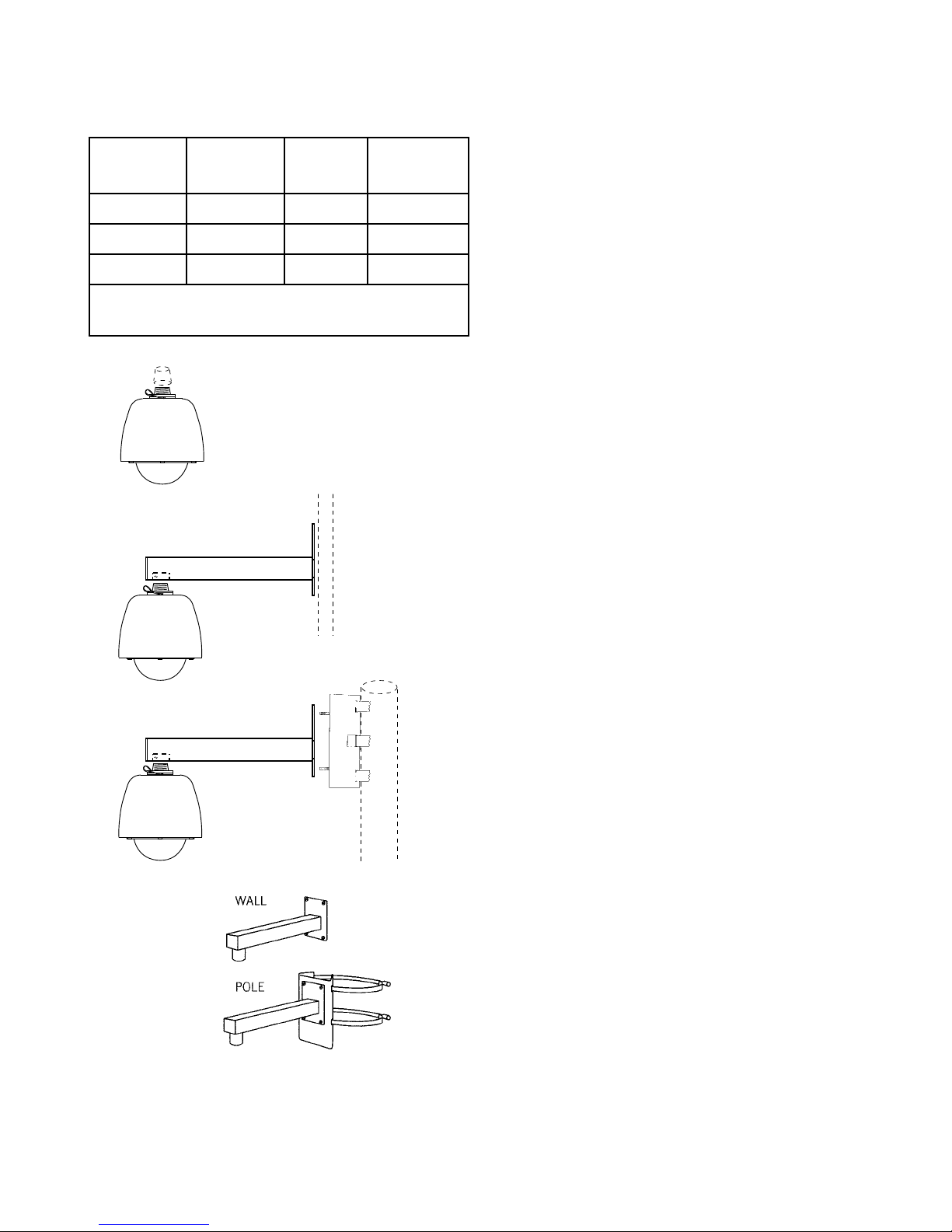
PENDANT MOUNT
WALL MOUNT
POLE MOUNT
INSTALLATION
Table 1. Basic Mounting Arrangements
MOUNT
CONFIG.
Pendant
Wall
Pole
NOTE: Dot ( • ) designates items supplied for each
mounting conguration.
iDOME ARM
•
• •
• • •
POLE
BRACKET
1. A DOS upload/burn program
2. Firmware for a 8051 microcontroller
3. Firmware for a DM642 digital media processor.
1.2.4 Functional Description
Video generated by the camera is reduced in
bandwidth using MPEG-4 compression. This compressed video is then sent via Ethernet packets on
CAT-5 cable to the PC. Control commands to the
camera and responses back use Ethernet communications over the same cable.
At the PC the video processing must be reversed. Ethernet packets are converted back to
video and then run through MPEG-4 decompression. This decompressed video is then processed
by viewer software and displayed on the screen of
the computer.
In addition to this video processing in the PC, the
software must send camera control commands over
the Ethernet cable as previously mentioned. The PC
control software must also process any responses
returned from the camera.
Within the iDome are an 8051 microcontroller
and a DM642 digital media processor. Both these
devices can be updated with rmware.
1.3 MECHANICAL CHARACTERISTICS
Although the iDome is a single mechanical assembly for installation purposes, it actually consists
of two primary mechanical subassemblies inside the
dome: (1) the camera module and (2) the positioner
(pan/tilt unit)).
All camera circuits are contained within a sealed
and pressurized environmental dome housing having either a clear or smoked window through which
the camera lens views outside scenes. This dome
is fully covered by a sun shield spaced slightly away
from the housing itself. This minimizes heat buildup
due to sunlight. Vent holes at the top of the dome
sunshield must be kept clear to maintain air ow.
Figure 4. Basic Mounting
Congurations
6X-1070D
The iDome is a sealed and pressurized (dry
nitrogen) unit intended for indoor or outdoor use
5
INSTALLATION
3940 IP iDome
under rain, snow, and other typical harsh weather
conditions.
A sealing type MS connector is used on the
housing and when mated with a similar MS type
cable connector they provide a good environmental
seal for the mating pins and sockets.
Both an Ethernet CAT-5e cable and a multiconductor power cable connect to a single cable plug.
These two cables and the attached plug are routed
to the iDome location and then passed through the
mounting pendant to provide for all signal, video,
and operating power connections. Pin functions and
layout are shown in gure 11.
2.0 INSTALLATION
This section of the manual provides general
instructions about installation of the iDome.
For descriptions of the various mounting arrangements to poles and buildings refer to section 6.
The actual installation should be performed by a
qualied installation professional familiar with all the
local code requirements and good practices for a
proper installation.
Always preplan the installation to be sure that all
required cabling and address assignments are completed. It may also be important to know the orientation of the iDome when it is mounted at its location.
The Schrader valve (gure 16) should be accessible
for adding dry nitrogen if necessary.
The model number label indicated a mechanical home reference for all iDomes. Electrical home
for panning is 90° clockwise from this position as
viewed from above.
Table 1 lists the three basic mounting arrangements. That pendant version consists of only the
iDome itself. The wall mount version of an iDome is
shipped with the wall mount arm. The pole mount
version is shipped with both the wall mount arm and
a pole mount bracket to which the wall mount arm
attaches.
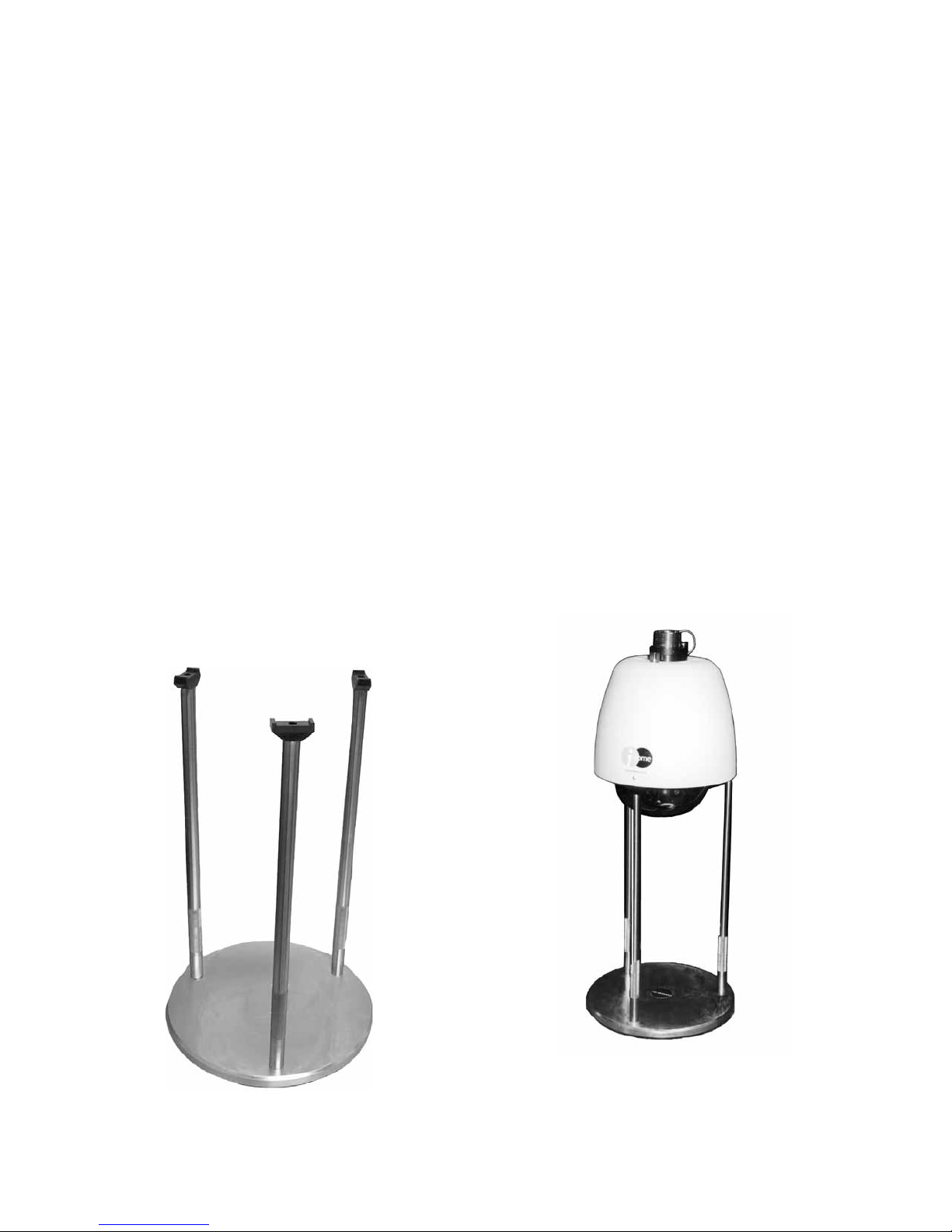
Figure 5. Model 8540B Test Stand (23-inch height).
( Model 8540A -not shown- provides 38-inch height)
6
6X-1070D

INSTALLATION
3940 IP iDome
Section 5 of this manual covers receiving
Table 2. Required Cable Characteristics
inspection, packing and return requirements for sending the iDome back to the
factory, and static discharge protections.
CONDUCTOR
FUNCTION
Static should mainly be of concern when
working inside a unit. This manual does
Ethernet
not cover disassembly of the Dome.
WARNING
The model 3945 versions of this iDome operate from 115 V ac — a voltage level that
can be dangerous. When working with this
model, use all appropriate care.
2.1 EQUIPMENT SUPPLIED
A cable connector kit (part number
1310230-011) is supplied as a loose part
POWER
Wire gauges depend on length of the cable run. This table assumes a 115 V ac iDome has a maximum 250 foot cable run,
For 24 V ac use, cable gauge 18 allows runs up to about 70
feet. 16 gauge is sufcient up to about 110 feet.
The Ethernet CAT5e cable is limited to about 300 feet due to
Ethernet timing considerations.
Use high quality cable suitable for the intended location.
for mating with the connector on top the
camera. Beyond that the model number of the camera determines what else is shipped with the camera.
Table 1 indicates what mounting arms and brack-
ets may also be supplied.
2.2 EQUIPMENT REQUIRED BUT NOT SUPPLIED
Each installation will have unique requirements
for necessary cables, equipment, and miscellaneous
accessory items. This list in table 3 is the most basic
items required for installing at the site location of the
iDome. Some of these items can be ordered with the
iDome and thus would be provided in those cases.
2.3 POWER REQUIREMENTS
The maximum power draw with pan/tilt motors
running and the heater on is 114 watts.
There are two versions of the iDome related to
voltage requirements:
• 24 V ac (Model 3944-590x / xxxx)
• 115 V ac (Model 3945-590x / xxxx)
The model number label is attached to the bottom
of an iDome. (Electrical home for camera pan is 90°
clockwise from this label viewed from above.)
TYPICAL CHARACTERISTICS
2 pairs twisted, 26 AWG minimum (CAT5e
cable or better)
115 V ac: 3-conductor, 18 AWG minimum
24 V ac: 5 conductors, gauge determined
primarily by length of cable run
Basic power consumption is 37 watts. When
both stepper motors are active, power consumption becomes 60 watts. When the thermostat applies power to the heaters, an additional 54 watts
is consumed. Thus the maximum power draw with
stepper motors both running and the heaters drawing power is 114 watts.
Power connections to the iDome are made
through a dedicated power cable. This cable and
the Ethernet CAT5e cable both connect to the
same 18 pin MS type plug for connection with the
mating camera connector.
One version of the Camera is wired for 115 V
ac. Pins “U” (high) and “T” (low) are used to provide 115 V ac Camera operating power. The AC
ground is pin G. The internal camera heater will
require that a minimum of 2.25 amps be available
(54 watts) in addition to the power required for the
camera and positioner (pan/tilt) motors).
A second version of the Camera is wired for
24 V ac. Pins “B” (high) and “T” (low) are used
to provide 24 V ac Camera operating power. To
provide power to the internal heaters, a separate
24 V ac input is used. Pin C is (high) and pin K is
(low). This heater input will require that a minimum
of 2.25 amps be available (54 watts).
Ac ground for both heater power and camera
power of the 24 V ac inputs is pin “G.”
7
6X-1070D

INSTALLATION
3940 IP iDome
Table 3. Items Required but Typically not Supplied
ITEM DESCRIPTION RECOMMENDED SOURCE
1 5/16 inch grade 316 stainless steel
hardware
2 Cable assembly Cohu CA-252A or CA-252B for 115 V ac models, or CA-252G
3 Connector Sealing Tape Coax Seal
4 Power source (114 watts) 24 V ac or 115 V ac, depending on camera model
5 Viewer & Control Software WinMPC.Net for setup and maintenance operations
6 Mounting arm See section 2.0 & section 7 for mounting choices
Commercial stock items
for the 24 V ac model
Table 2 lists basic characteristics that are required for a typical cable interconnection with the
iDome.
The Ethernet conductors should be at least
26 gauge or larger twisted pairs. With these data
conductors it is desired to minimize capacitance
loading and thus shielded type CAT5e cables
should not be used. However in problem installations with high interference levels, on overall
outer shield can be used if desired. Individual
shields over the twisted pairs should be the last
choice. In most situations standard unshielded
twisted pair (UTP) CAT5e cable can be used.
The power conductors should be as heavy a
gauge as possible. Cohu cables use paralleled
22 gauge conductors for the 24 V ac power cable
and 18 gauge for the 115 V ac cables.
This problem is especially acute with the 24
V ac version of the iDome since it draws much
more current than the 115 V ac version. Thus 24
V ac versions typically have shorter allowable
cable runs unless the power wiring is increased
to a much larger size. To minimize this problem,
operating power and heater power are supplied
on separate inputs for a 24 V ac iDome. And
even so, wires within the cable are paralleled to
increase current carrying capacity. See gure 10
for an example of these paralleled power wires.
Maximum cable length for the Type CA-252G
cable is 80 feet.
When the heaters turn on under thermostatic
control during low ambient temperatures the
voltage drops at the iDome due to resistance in
8
the wires. With the 24 V ac version this does not
decrease operating power since it is on a separate
input, but for the 115 V ac version, operating voltage
cannot be allowed to drop below the requirements
of the iDome when heaters are energized by the
thermostat.
Power wiring of greater sizes reduces this voltage drop when heaters cycle on and off. When
designing a custom installation it is best to perform
a few Ohm’s Law calculations to determine what is
the minimum allowable size for power wiring. Length
of power wires both to and from the camera must be
considered when doing these calculations.
And remember that the CAT5e Ethernet cable to
the iDome cannot be longer than about 300 feet due
to Ethernet timing considerations.
2.4 CABLING REQUIREMENTS
Table 4 lists typical cables available for use with
the iDome. This table summarizes the characteristics of each cable. “Prepped” in the table indicates
that the wire leads are stripped and pre tinned with
solder for attachment to a terminal strip or similar
device.
Note that two of these cables are listed for use
with 115 V ac iDomes only.
Cable CA-252G is for the 24 V ac versions of the
iDome. Note that the maximum length of this cable
is 80 feet due to power demands of the heaters, but
longer lengths could become an issue for the camera power, too.
6X-1070D
 Loading...