

COHU 3940 Analog iDome, 3940 IP iDome Installation Manual
INSTALLATION
COHU, INC. ELECTRONICS DIVISION
Installation Manual
3940 Analog iDome and
3940 IP iDome
CAMERA/POSITIONER SYSTEM
Phone: 858-277-6700
FAX:
858-277-0221
Cohu Electronics • 3912 Calle Fortunada • San Diego, CA 92123-1827
6X-1070
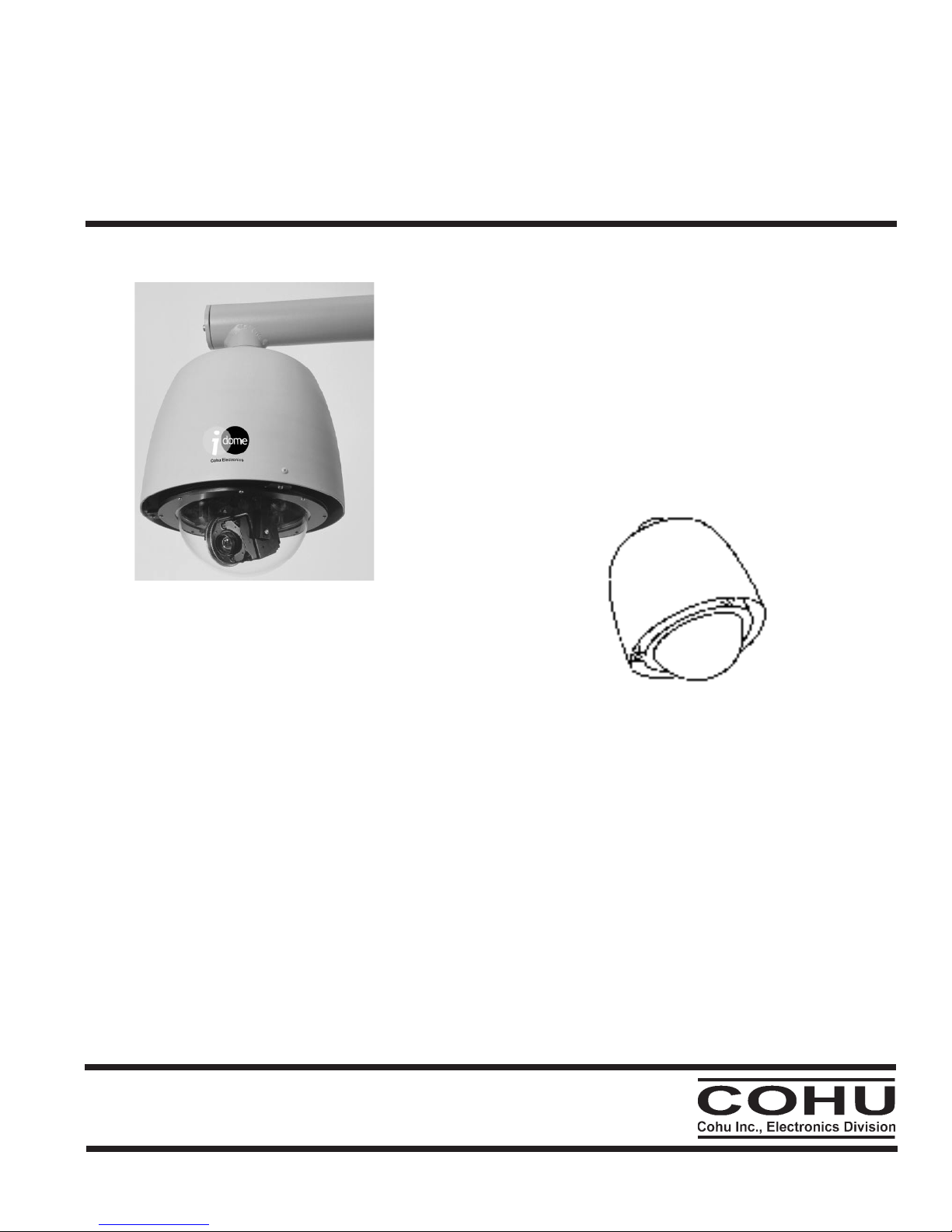
Figure 1. iDome
July 17, 2006
info@cohu.com
www.cohu-cameras.com
1
INSTALLATION
SECTION TITLE PAGE
1.0 GENERAL DESCRIPTION
3
1.1 Electrical Characteristics
3
1.2 Mechanical Characteristics
6
2.0 INSTALLATION
7
2.1 Installation Introduction 8
2.2 Equipment Supplied 12
2.3 Equipment Required But Not Supplied 14
2.4 Power Requirements 14
2.5 Pendant Mount Installation 16
2.6 Wall Mount Installation 16
2.7 Pole Mount Installation 17
2.8 Alternate Mounting Methods 19
2.9 Cabling Requirements 19
2.10 Analog Output Video Capture 24
2.11 Viewer GUI 24
3.0 OPERATION
25
4.0 MAINTENANCE
25
4.1 Firmware Uploads 25
4.2 Preventive Maintenance 25
5.0
SHIPPING AND STATIC
DISCHARGE CONSIDERATIONS
26
5.1 Unpacking & Receiving Inspection 26
5.2 Preparation for Shipment & Storage 26
5.3 Static Discharge Protection 27
FIGURE TITLE PAGE
1 iDome 1
2 Model Number Interpretation Diagram 6
3 iDome Dimensions 6
4 Basic Model Configurations 7
5 Model 8540B Test Stand 8
6 Typical Test Cables, 115 V ac 9
7 Typical RS-232 to RS-422 Converter 10
8 Quick Disconnect Assemby 11
9 Wall Mount Arm 11
10 Arm Dimensions 12
11 Typical Pole Mount 13
12 iDome Quick Disconnect Mounting 14
13 Strap Wrench 14
14 Pole Mount Dimensions 15
15 Mast Arm Mount 15
16 Interconnection Diagram, iDome to Equipment Cabinet (typ) 17
17 Local Operation Test Setups 18
18 Type CA-252A Cable, Stripped Power & Ethernet Leads 20
19 Type CA-252B Cable, 115 V ac Plug & RJ-45 Etnernet Plug 20
20 Type CA-252P Cable, All Stripped Leads 21
21 Type CA-252Q Cable, Stripped RS-422 Leads 21
22 Camera Connector Pinout Diagram 22
23 iDome Maintenance Features 24
TABLE TITLE PAGE
1 Specifications 4
2 Basic Mounting Arrangements 7
3 Required Cable Characteristics 15
4 Type CA-252 Cable Connectors 19
5
Camera Ethernet Pinout vs. Standard
RJ-45 Pinout
22
6 24 V ac iDome Connector Functions 23
7 115 V ac iDome Connector Functions 23
LIST OF SECTIONS
LIST OF TABLES
LIST OF FIGURES
2
6X-1070

INSTALLATION
1.0 GENERAL DESCRIPTION
The 3940 iDome series is an integrated camera/
positioner unit that combines a high performance
digital signal processing camera, pan-and-tilt, and
control receiver for communications into one integrated package (figure 1). The 3940 is available in
two basic versions:
Analog Version: The Model 394x-x1xx has
NTSC video output and control functions are handled by RS-422. Firmware changes can be uploaded via an Ethernet connection
IP Version: The Model 394x-x9xx communi
cates via Ethernet and supplies video via Ethernet
IP video packets. On this IP version RS-422 is not
used. An IP dome is configured to connect to a hub.
Connecting it directly to a computer will require use
of a crossover cable or adapter.
Throughout this manual the entire assembly will
typically be referred to as the “iDome” or just the
“Dome.”
There will also be references to the “Analog”
version and the “IP” version when this distinction is
important.
Specifications are contained in table 1 and a
model number interpretation diagram is provided in
figure 2. This diagram can be used to interpret an
existing model number.
1.1 ELECTRICAL CHARACTERISTICS
The camera uses digital signal processing. It has
an internal source ID generator. Integration control
plus a built-in video storage card provides full color
continuous video even at very low light levels.
standard pan-preset or manual control, the iDome
can move with a pan speed of 250° per second.
This iDome will operate in temperature ranges
from -34° to +74° C and with winds of up to 90 mph.
The enclosure protects against salt, grime, dirt, and
moisture.
The integrated receiver/driver, contained within
the iDome, communicates using Cohu protocol
messages and will also control the digital DSP
camera functions. All iDome functions are operable
via either RS-422 or Ethernet serial communications
depending on the version.
In case of power failure, all 64 preset positions
are stored in nonvolatile memory.
Each iDome “address” within a surveillance system can be selected electronically from the Monitoring Center. There are no mechanical dip switches
to set at the camera, and each unit responds to the
central command only if addressed. This provides
greater integration flexibility for the designer and
more dynamic camera control for the operator.
Privacy zones can be set up using polygon
shaped windows drawn with the Viewer/Gui soft
ware. These blanking windows are generated elec
-
tronically within the digital signal processing (DSP)
and provide positive control of such areas.
Electronic image stabalization (EIS) is available
for one version of the two 23X camera modules and
it is a standard feature for the 35X camera module.
This EIS feature helps to minimize the effects of
slight vibrations on a Dome in certain mounting situations — such as when it is mounted on a tall pole.
1.1.1 Control Software
The iDome speeds are variable with maximums
of 250° per second for pan and tilt. Pan range is
a continuous 360 degrees while the tilt range is 0
to 90 degrees from the horizontal with auto-flip at
the 90° point. There are 64 preset positions with a
preset accuracy of 0.1 degree. When responding to
6X-1070
The analog and the IP versions of this Dome
each require different software to control them and
to view their video. Separate manuals cover these
Viewers. Refer to Cohu manual part number 6X1071 for the IP viewer/GUI manual and part number
6X-1072 for the analog viewer/GUI manual.
3
INSTALLATION
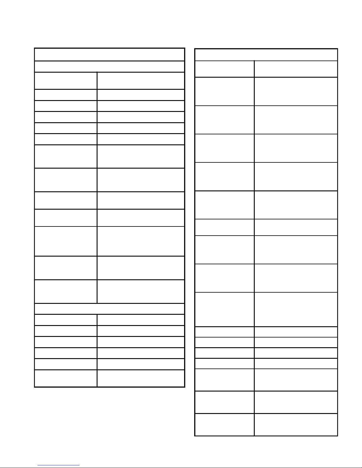
SYSTEM SPECIFICATIONS
PAN/TILT DRIVE
Angular Travel
360° continuous pan range
-90° to +5° tilt range
Pan Speed (preset) 250°/second
Pan Speed (manual) 0.1° to >80°/sec
Tilt Speed (preset) 80°/sec
Tilt Speed (manual) 0.1° to >40°/sec
Preset Accuracy >0.1°
Presets
64 preset positions (pan, tilt, zoom,
focus coordinates, & 24 character
ID label)
Video Tours
8 tours, each consisting of 32
presets with dwell time per preset
per tour
Sector Zones
Up to 16 programmable zones in
the horizontal plane
Privacy Zones
8 zones can be set by drawing
polygons on the scene
Compass Direction
8 or 16 direction points (i.e., north,
NE, east, SE, south, SW, west, &
NW) can be displayed. Function
can be on/off, 3 sec, or permanent.
Absolute Position
Displayed in 0 to 359° azimuth &
+14° to -95° elevation. Function can
be on/off, 3 sec, or permanent.
Cloning
Positioner settings (presets, title,
etc) can be saved to a file for easy
duplication
TITLE GENERATION
Camera ID 2 lines of 24 characters
Preset ID 1 line of 24 characters
Sector Zone 1 line of 24 characters per zone
Privacy Zone 1 line of 24 characters per zone
Alarm Label 2 lines of 24 characters
Compass/Position
1 line. Includes compass direction
and absolute position
CAMERA SPECIFICATIONS
Imager
1/4 inch interline transfer color CCD
NTSC for analog version of iDome
Resolution
23X lens:
23X lens & EIS:
35X lens & EIS:
470 horizontal tv lines
470 horizontal tv lines
520 horizontal tv lines
Pixels
23X lens:
23X lens & EIS:
35X lens & EIS:
724 X 494
711 X 485
768 X 494
Progressive Scan
23X lens:
23X lens & EIS:
35X lens & EIS
Yes
Not Supported
Yes
Lens Zoom
23X lens:
23X lens & EIS:
35X lens & EIS
3.6 to 82.8 mm, f1.6 (w) f3.7(t)
3.6 to 82.8 mm, f1.6 (w) f3.7(t)
3.4 to 119 mm, f1.4 (w) f4.2(t)
Lens Hor. Angle of View
23X lens:
23X lens & EIS:
35X lens & EIS
54° (w) 2.5° (t)
41.5° (w) 1.9° (t)
55.8° (w) 1.7° (t)
Iris/Focus/Shutter
Operation
Auto/Manual
Wide Dynamic Range
23X lens:
23X lens & EIS:
35X lens & EIS
On/off
Not supported
On/off
EIS at 5 Hz Suppression
23X lens:
23X lens & EIS:
35X lens & EIS
Not Supported
20 dB suppression 7 to17 Hz
20 dB suppression 7 to17 Hz
EIS at 16Hz
Suppression
23X lens:
23X lens & EIS:
35X lens & EIS
Not Supported
20 dB suppression 3 to13 Hz
20 dB suppression 3 to13 Hz
Digital Zoom Auto/manual (12X)
White Balance Auto/manual
Sync Crystal / phase adjust line lock
S/N >50 dB
Sensitivity (scene)
23X lens:
3 lux at 1/60 sec (color day)
0.2 lux at 1/4 sec (color day)
0.02 lux at 1/4 sec (mono night)
Sensitivity (scene)
23X lens & EIS:
2 lux at 1/60 sec (color day)
0.2 lux at 1/4 sec (color day)
0.01 lux at 1/4 sec (mono night)
Sensitivity (scene)
35X lens & EIS
1 lux at 1/60 sec (color day)
0.1 lux at 1/4 sec (color day)
0.01 lux at 1/4 sec (mono night)
Table 1. Specifications
4
6X-1070
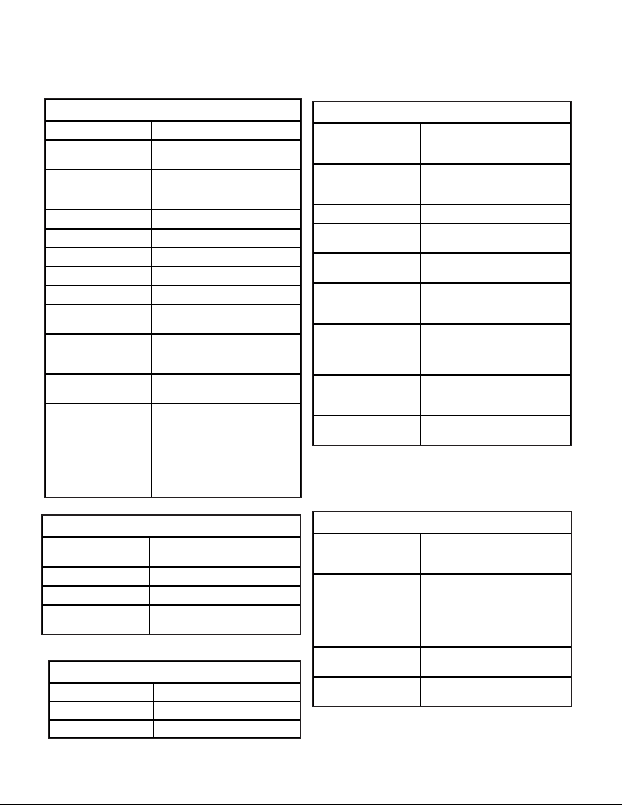
VIDEO SPECIFICATIONS
VLIW/DSP TI TMS320DM642-600
Video Encoding
MPEG4 ISO/IEC 14496-2 ASP;
RTP/UDP stack
Resolution
640 x 480 (VGA)
640 X 240 (2 CIF)
320 X 240 (1 CIF)
Frame Rates 30, 15, 8, 4, 2, 1
Bit Rates 64 k to 3 MB
Data Encoding RTSP/TCP/IP stack
Image Memory 96 MB SDRAM
Network 100Base T fast Ethernet connection
Image Storage
1 to 30 minutes, depending on
image management settings
Video Motion
8 separate windows, 1200 ROI per
window, 255 sensitivity levels, fixed
or progressive threshold settings.
Logo Insertion
Supports bmp image insertion for
logo
Privacy / Masking Zones
Supports 64 polygon mask areas
(0.8° per side, with 0.1° resolution).
Each polygon mask can be turned
on/off at a user defined zoom
position. All video below & above
user-defined tilt angle can be
masked. Masking areas adjust in
size relative to zoom level.
ENVIRONMENTAL SPECIFICATIONS
Protection Rating
IP67 & NEMA 4X; sealed &
pressurized to 5 psi with dry
nitrogen
Ambient Temp. Limits
Operating:
Storage:
-34 to 50 °C (-27 to 122 °F)
-40 to 85 °C (-40 to 185 °F)
Humidity Up to 100 percent relative humidity
Vibration
Conforms to NEMA TS2, paragraph
2.1.9
Shock
Conforms to NEMA TS2 paragraph
2.1.10
Altitude
Sea level to equivalent of 3,000
meters / 10, 000 feet (508 mm/20
inches of mercury)
Air Contaminants
Withstands exposure to sand, dust,
fungus, & salt atmosphere, per MILSTD-5400T, paragraph 3.2.24.7,
3.2.24.8, & 3.2.24.9
Acoustics
Can withstand environments greater
than 150 dB continuously for 30
minutes
EMI
FCC rules, part 15, subpart J, for
class B devices
COMMUNICATIONS SPECIFICATIONS
Data Format
RS-422 (analog version)
IEEE 802.3U (IP version)
PTZ Latency <200 ms (typical)
Protocol Cohu
Firmware
Stored in flash memory, uploaded
via Ethernet port
POWERS SPECIFICATIONS
Power Input
120 V ac (89 V ac to 135 V ac),
60 Hz
or 24 V ac 60 Hz
Power Consumption
Basic power consumption is 37 W.
P/T stepper motors add 23.
Heaters add 54 W.
Total maximum draw is 114 W with
heaters on and pan/tilt both
operating.
Power Interruption
Conforms to NEMA TS2 paragraph
2.1.4
Power Transients/
Interruptions
Conforms to NEMA TS2 paragraph
2.1.6
MECHANICAL SPECIFICATIONS
Weight 14 lb
Dimensions See figure 3
Connector 18 pin MS type
INSTALLATION
Table 1. Specifications (continued)
6X-1070
5
INSTALLATION
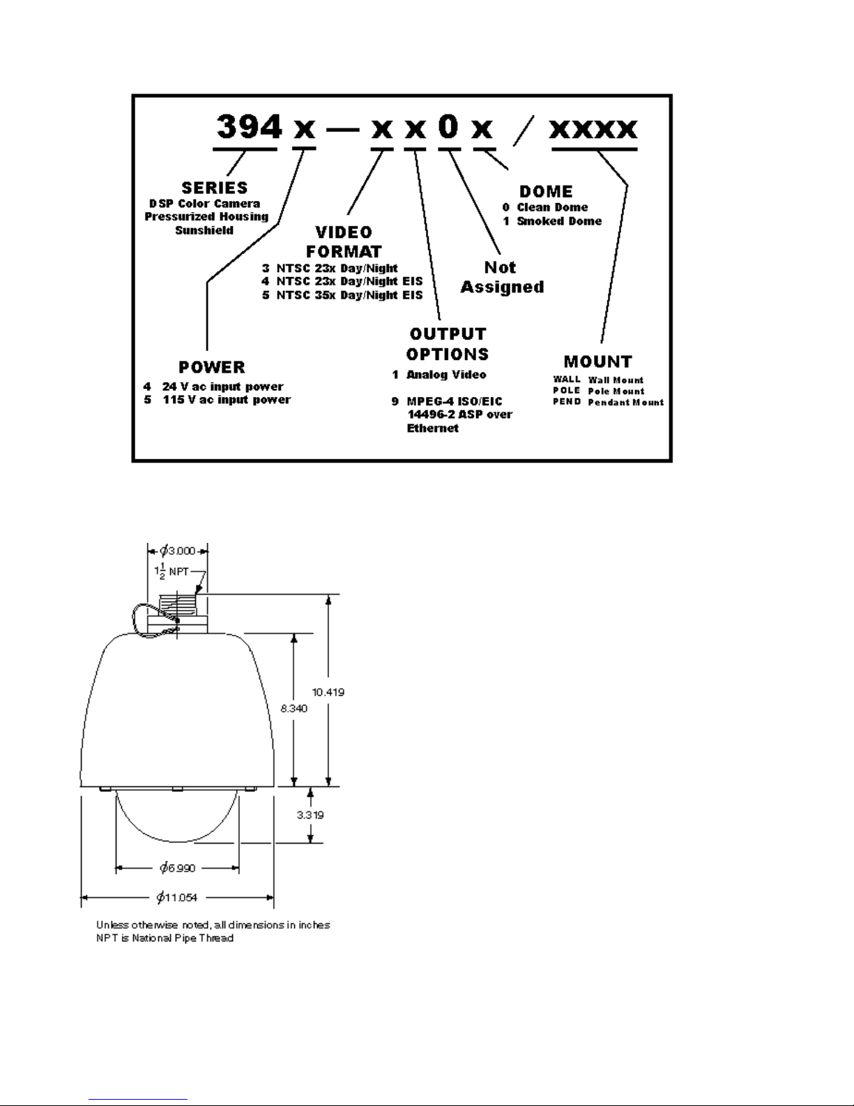
Figure 2. Model Number Interpretation Diagram
1.2 MECHANICAL CHARACTERISTICS
Although the iDome is a single mechanical assembly for installation purposes, it actually consists
of two primary subassemblies inside the dome: (1)
the camera and (2) the positioner.
All camera circuits are contained within a sealed
and pressurized environmental dome housing having either a clear or smoked window through which
the camera lens views outside scenes. This dome
is fully covered by a sun shield spaced slightly away
from the housing itself. This minimizes heat buildup
due to sunlight. Vent holes at the top of the dome
must be kept clear to maintain air flow.
The iDome is a sealed and pressurized (dry
nitrogen) unit intended for indoor or outdoor use
under rain, snow, and other typical harsh weather
conditions.
Figure 3. i Dome Dimensions
6
Communications circuits contained within the
iDome are also protected from outdoor weather
conditions.
6X-1070
MOUNT
CONFIG.
iDOME ARM
POLE
BRACKET
Pendant
•
Wall
• •
Pole
• • •
NOTE: Dot (
• )
designates items supplied for each mounting
configuration.
INSTALLATION
Table 2. Basic Mounting Arrangements
A sealing type MS connector is used on the
housing and when mated with a similar MS type
cable connector a good environmental seal is provided for the mating pins and sockets.
A single multiconductor cable is routed to the
iDome location and then passed through the mounting pendant to provide for all signal, video, and operating power connections. Pin functions and layout
are shown in figure 22.
2.0 INSTALLATION
This section of the manual provides general
instructions about installation of the iDome using
various mounting arrangements.
The actual installation should be performed by a
qualified installation professional familiar with all the
local requirements for proper installation.
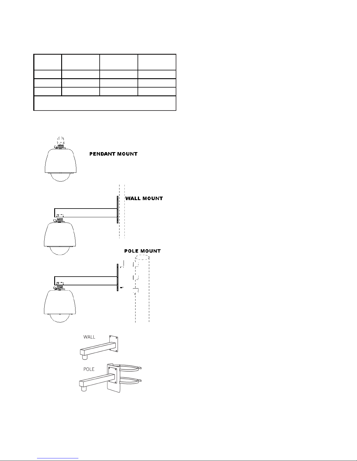
Figure 4. Basic Mounting
6X-1070
Configurations
Always preplan the installation to be sure that all
required cabling and address assignments are completed. It may also be important to know the orientation of the iDome when it is mounted at its location.
The Schrader valve (figure 23) should be accessible
for adding dry nitrogen if necessary.
The model number label indicated a mechanical home reference for all iDomes. Electrical home
for panning is 90° clockwise from this position as
viewed from above.
Table 2 lists the three basic mounting arrange
ments. That pendant version consists of only the
iDome itself. The wall mount version of an iDome is
shipped with the wall mount arm. The pole mount
version is shipped with both the wall mount arm and
a pole mount bracket to which the wall mount arm
attaches.
Section 5 of this manual covers receiving inspection, packing and return requirements for a return to
the factory, and static discharge protections. Static
should mainly be of concern when working inside a
unit, and this manual does not cover disassembly of
the Dome.
7
INSTALLATION
WARNING
One versions of the iDome operate from voltages
that can be dangerous: model 3945 (115 V ac). Use
all appropriate care when installing and maintaining
this version of the iDome.
2.1 INSTALLATION INTRODUCTION
This section is a brief overview of the various
mounting types. The installation methods described
in this manual are a general overview of typical installations. Since the particular conditions at various
installation sites can vary widely, it is best if the ac
tual installation is performed only by a professional
installer familiar with all local requirements.
2.1.1 Basic Mounting Configurations
An iDome can typically be mounted in any one of
three mechanical configurations (figure 4):
2.1.1.1 Pendant Mount
The basic configuration. The iDome hangs directly from a supplied 1.5-inch female NPT (national
pipe thread) support. This support must provide
for the connector of a multiconductor cable to pass
down through the 1.5-inch pipe nipple for mating
with the iDome.
2.1.1.2. Wall Mount
This mounting arrangement requires an arm that
bolts to the wall. The iDome hangs from the end of
this arm.
2.1.1.3. Pole Mount
This mounting arrangement is similar to the Wall
Mount — except that the mounting arm attaches to
a bracket fastened to a pole instead of directly bolting to a wall.
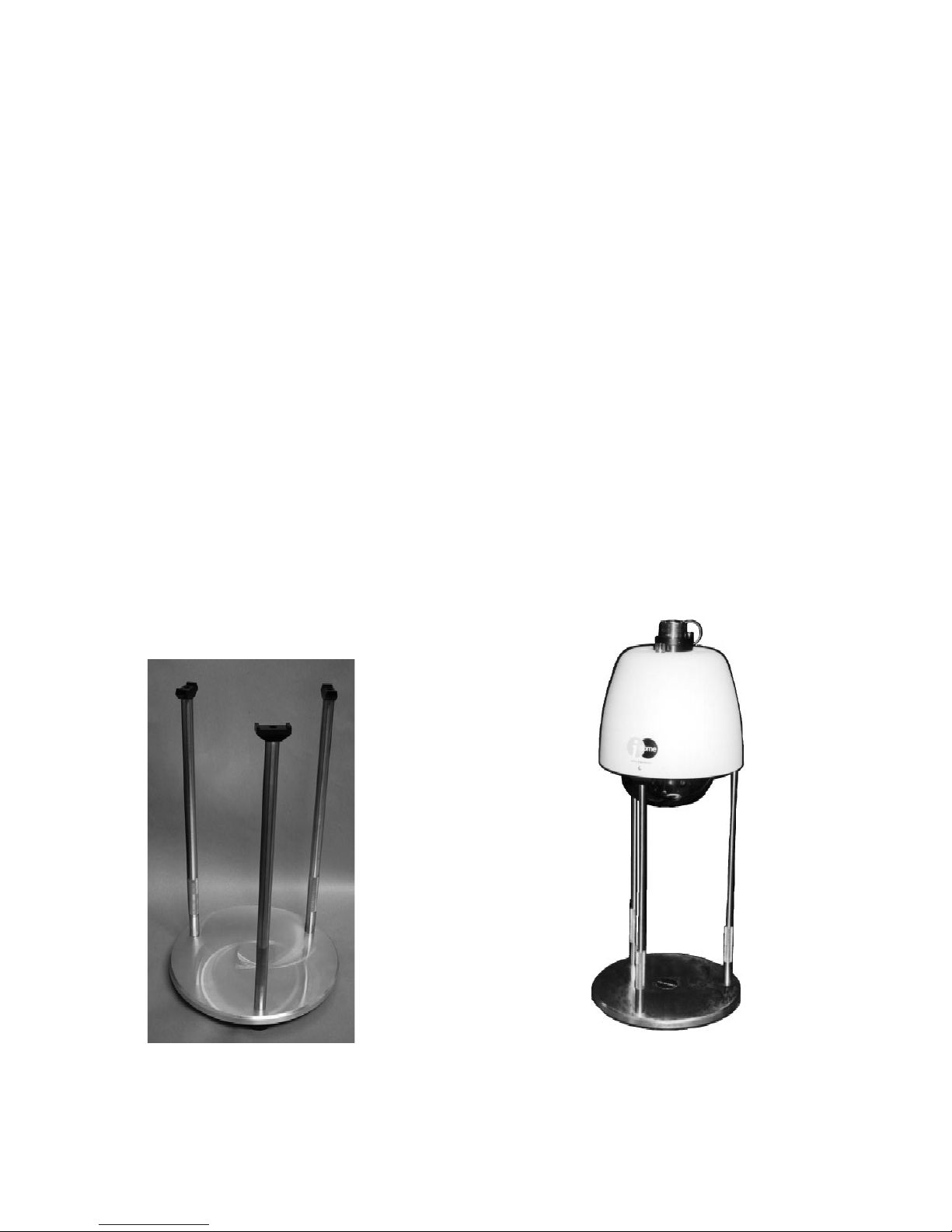
Figure 5. Model 8540B Test Stand (23-inch height).
( Model 8540A -not shown- provides 38-inch height)
8
6X-1070
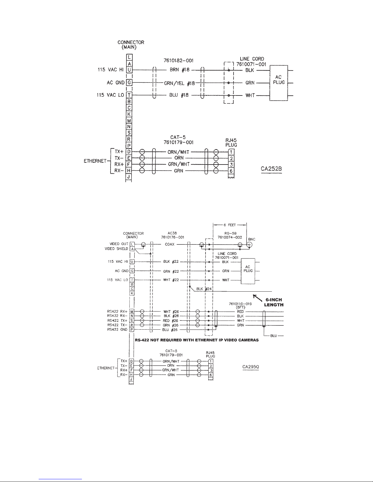
INSTALLATION
IP Video Models
Firmware
Upload
Only
Figure 6. Typical Test Cables, 115 V ac
6X-1070
Analog Video Models
9
 Loading...