

COHU 3920 SERIES Installation And Operation Manual
3920 iDOME
INSTALLATION AND OPERATION
COHU, INC. ELECTRONICS DIVISION
Installation and Operation Manual
3920 SERIES
iDOME CAMERA/POSITIONER SYSTEM
Technical Manual 6X-1026E
www.cohu-cameras.com/content/contactus
6X-1026E
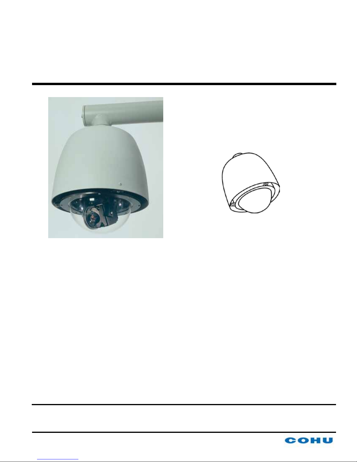
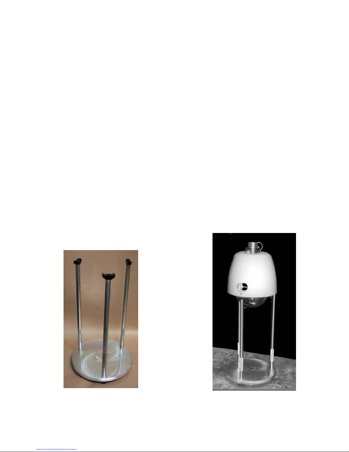
Figure 1. iDome
June 21, 2012
www.cohu-cameras.com
info@cohu.com
1

INSTALLATION AND OPERATION
TABLE
OF CONTENTS
LIST OF FIGURES
3920 iDOME
SECTION TITLE PAGE
1.0 GENERAL DESCRIPTION
1.1 Electrical Characteristics 3
1.2 Mechanical Characteristics 4
2.0 INSTALLATION
2.1 Installation Introduction 6
2.2 Equipment Supplied 9
2.3 Equipment Required But Not Supplied 12
2.4 Power Requirements 13
2.5 Pendant Mount Installation 16
2.6 Wall Mount Installation 16
2.7 Pole Mount Installation 17
2.8 Alternate Mounting Methods 17
2.9 Testing Cables 16
2.10 System Cabling Requirements
2.11 GUI Interface 26
3.0 OPERATION
3.1 Local Panel Control 30
3.2 Local Laptop PC Control 31
4.0 MAINTENANCE
4.1 Preventive Maintenance 31
SHIPPING AND STATIC DIS-
5.0
CHARGE CONSIDERATIONS
5.1 Unpacking & Receiving Inspection 32
5.2 Preparation for Shipment & Storage 32
5.3 Static Discharge Protection 32
3
5
17
30
31
32
LIST OF TABLES
TABLE TITLE PAGE
1 Basic Mounting Arrangements 5
2 Required Cable Characteristics 14
3 Common System Cables Used 18
4 iDome Connector Functions 28
5 Communications Settings 28
6 Specications 34
FIG. TITLE PAGE
1 iDome 1
2 Model Number Interpretation Diagram 4
3 Dimensions, 3920 5
4 Basic Mounting Congurations 6
5 Model 8540B Test Stand 7
6 Type CTC-29 Cable, Test/ Setup, Wiring Diagram 8
7 Typical RS-232 to RS-422 Converter 8
8 Type CTC-33 Cable, 9200 Control Panel Connection 9
9 Quick Disconnect Assemby 10
10 Wall Mount Arm 10
11 Arm Dimensions 11
12 Typical Pole Mount 12
13 iDome Quick Disconnect Mounting 13
14 Strap Wrench 14
15 Pole Mount Dimensions 14
16 Mast Arm Mount 14
17 Intreconnection Diagram, iDome to Local Control Panel 15
18 Interconnection Diagram, iDome to Equipment Cabinet 16
19 Cable CA-292A 24 Vac (RS-232) All Prepped Leads 19
20 Cable CA-292B 24 Vac (RS-232) Prepped/D9/BNC 19
21 Cable CA-293A 24 Vac (RS-422) All Prepped Leads 20
22 Cable CA-293B 24 Vac (RS-232) Prepped/D9/BNC 20
23 Cable CA-293M 115 Vac (RS-422) RJ-45/Prepped/BNC 21
24 Cable CA-295E 115 V ac (RS-422), All Prepped Leads 22
25 Cable CA-295F 115 Vac (RS-422) Plug, Prepped, BNC 22
26 Cable CA-295G 115 Vac (RS-422) Plug, 422-232, BNC 23
27 Cable CA-295H 115 Vac (RS-232) Single AMP Connector 23
28 Cable CA-295M 115 Vac (RS-232) Plug, RJ45, BNC 24
29 Cable CA-296A 115 V ac (RS-232), All Prepped Leads 25
30 Cable CA-296B 115 Vac (RS-232) Plug, Prepped, BNC 25
31 Cable CA-296C 115 Vac (RS-422) Plug, D9F, BNC 26
32 iDome Pin Layout and Functions 27
33 Typical About WinMPC Screen 29
34 Typical WinMPC Main Screen 29
35 Typical WinMPC Communications Setup Screen 30
36 iDome Maintenance Features 33
2
6X-1026E

3920 iDOME
1.0 GENERAL DESCRIPTION
The iDome series is an integrated camera/positioner unit that integrates a high performance digital
signal processing camera, pan-and-tilt, and control
receiver for communications into one integrated
package (gure 1).
Throughout this manual the entire assembly will
typically be referred to as the “iDome.”
Specications are contained in table 6 at the end
of this manual and a model number interpretation
diagram is provided in gure 2. This diagram can
be used to interpret an existing model number. An
iDome can be operated via either RS-232 or RS422 communications depending on which pins of
the connector are used. Thus there is no model
number designation to reect a choice for the communications mode.
WARNING
Two versions of the iDome operate from voltages that can be dangerous: model 3925 (115
V ac) and model 3923 (230 V ac). Use all
appropriate care when installing and maintaining either of these versions of the iDome.
1.1 ELECTRICAL CHARACTERISTICS
INSTALLATION AND OPERATION
a continuous 360 degrees while the tilt range is 0
to 90 degrees from the horizontal with auto-ip at
the 90° point. There are 64 preset positions with a
preset accuracy of 0.1 degree. When responding to
standard pan-preset or manual control, the iDome
can move with a pan speed of 250° per second.
This iDome will operate in temperature ranges
from -34° to +74° C and with winds of up to 90 mph.
The enclosure protects against salt, grime, dirt, and
moisture.
The integrated receiver/driver, contained within the
iDome, communicates using Cohu protocol messages and will also control the digital DSP camera
functions. All iDome functions are operable via
either RS-232 or RS-422 serial communications.
The iDome is fully compatible with existing Cohu
controllers. In case of power failure, all 64 preset
positions are stored in nonvolatile memory.
Each iDome “address” within a surveillance system can be selected electronically from the Monitoring Center. There are no mechanical dip switches
to set at the camera, and each unit responds to the
central command only if addressed. This provides
greater integration exibility for the designer and
more dynamic camera control for the operator
The camera uses digital signal processing. It has
an internal source ID generator. Integration control
plus a built-in video storage card provides full color
continuous video even at very low light levels.
The iDome speeds are variable with maximums
of 250° per second for pan and tilt. Pan range is
NOTE: This equipment has been tested and found to comply with the
limits for a Class A Digital Device, pursuant to Part 15 of the FCC Rules.
These limits are designed to provide reasonable protection against
harmful interference when the equipment is operated in a commercial
environment. This equipment generates, uses, and can radiate radio
frequency energy and, if not installed and used in accordance with the
instruction manual, may cause harmful interference to radio communications. Operation of this equipment in a residential area is likely to cause
harmful interference in which case the user will be required to correct
the interferecne at his own expense.
1.1.1 Control Software
WinMPC
WinMPC Graphical User Interface (GUI) software
is available for setting the address and performing
eld tests when connected to a single camera. (It
cannot be used to control more than one camera at
This device complies with Part 15 of the
FCC Rules. Operation is subjected to the
following two conditions: (1) this device
may not cause harmful interference and (2)
this device must accept any interference
received, including interference that may
cause undesired operation.
CAUTION: Changes or modications to
this device not expressly approved by
Cohu Electronics could void the user’s
authority to operate the device.
6X-1026E
3
INSTALLATION AND OPERATION
MODEL NUMBER INTERPRETATION DIAGRAM
392×—××0×—××××
3920 iDOME
SERIES
DSP color/mono 1/4 inch
progressive scan dome
camera with zoom lens
POWER
424 Vac
5115 Vac
VIDEO
5 NTSC 35X Day/Night EIS
7PAL Phase Adjust Line Lock
8 PAL 35X Day/Night EIS
EIS is Electronic Image Stabilization
Figure 2. Model Number Interpretation Diagram
a time.) The WinMPC software can be obtained at
no cost from either the Cohu-Cameras.com web site
or by mail on CD.
CAMS
The CAMS software is intended for controlling
multi-iDome systems when the Cohu MPC Master
Control Panel is the central control “intelligence” for
the system. All control and response commands
among the various equipment in the system pass
through the Master Control Panel.
MOUNT
PEND
FEATURES
Low Pressure Indicator
Heaters
Variable Speed
360° pan
POLE
WALL
DOME
0Clear
1Smoked
PROTOCOL
1Cohu Protocol
American Dynamics
Pelco D
Ultrak
Vicon
Javelin
Kalatel
Philips / Bosch
2NTCIP Protocol
two primary subassemblies inside the dome: (1) the
camera and (2) the positioner.
All camera circuits are contained within a sealed
and pressurized environmental dome housing
having either a clear or a smoked window through
which the camera lens views outside scenes.
This dome is fully covered by a sun shield spaced
slightly away from the housing itself. This minimizes
heat buildup due to sunlight. Vent holes at the top
of the dome must be kept clear to maintain air ow.
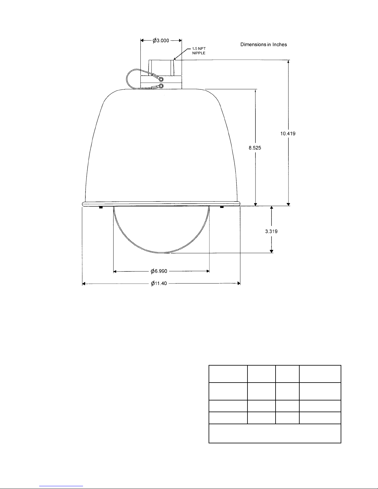
Figure 3 gives dimensions of the iDome.
Typical Protocol
Selections
NetCAMS
The NetCAMS software is intended for controlling
multi-iDome systems when a Windows based PC is
the central control “intelligence” for the system. All
control and response commands among the various equipment in the system pass through the Net
Cams Server.
1.2 MECHANICAL CHARACTERISTICS
Although the iDome is a single mechanical assembly for installation purposes, it actually consists of
4
The iDome is a sealed and pressurized (dry nitrogen) unit intended for indoor or outdoor use under
rain, snow, and other typical harsh weather conditions.
Communications circuits contained within the
iDome are also protected from outdoor weather
conditions.
A sealing type MS connector is used on the housing and when mated with a similar MS type cable
connector a good environmental seal is provided for
the mating pins and sockets.
6X-1026E
3920 iDOME
INSTALLATION AND OPERATION
Figure 3. Dimensions, 3920 iDome
A single multiconductor cable is routed to the
iDome location and then passed through the mounting pendant to provide for all signal, video, and operating power connections. Pin functions and layout
are shown in gure 32.
2.0 INSTALLATION
This section of the manual provides general
instructions about installation of the iDome using
various mounting arrangements.
The actual installation should be performed by a
qualied installation professional familiar with all the
local requirements for proper installation.
6X-1026E
Table 1. Basic Mounting Arrangements
MOUNT
CONFIG.
Pendant
Wall
Pole
NOTE: Dot ( • ) designates items supplied for
each mounting conguration.
iDOME ARM
•
• •
• • •
POLE
BRACKET
5
INSTALLATION AND OPERATION
3920 iDOME
Always preplan the installation to be sure that all
required cabling and address assignments are completed. It may also be important to know the orientation of the iDome when it is mounted at its location.
The Schrader valve (gure 36) should be accessible
for adding dry nitrogen if necessary.
The model number label indicated a mechanical home reference for all iDomes. Electrical home
for panning is 90° clockwise from this position as
viewed from above.
Table 1 lists the three basic mounting arrangements. That pendant version consists of only the
iDome itself. The wall mount version of an iDome is
shipped with the wall mount arm. The pole mount
version is shipped with both the wall mount arm and
a pole mount bracket to which the wall mount arm
attaches.
Section 5 of this manual covers receiving inspection, packing and return requirements for a return to
the factory, and static discharge protections.
PENDANT MOUNT
2.1 INSTALLATION INTRODUCTION
This section is a brief overview of the various
mounting types. The installation methods described
in this manual are a general overview of typical installations. Since the particular conditions at various
installation sites can vary widely, it is best if the actual installation is performed only by a professional
installer familiar with all local requirements.
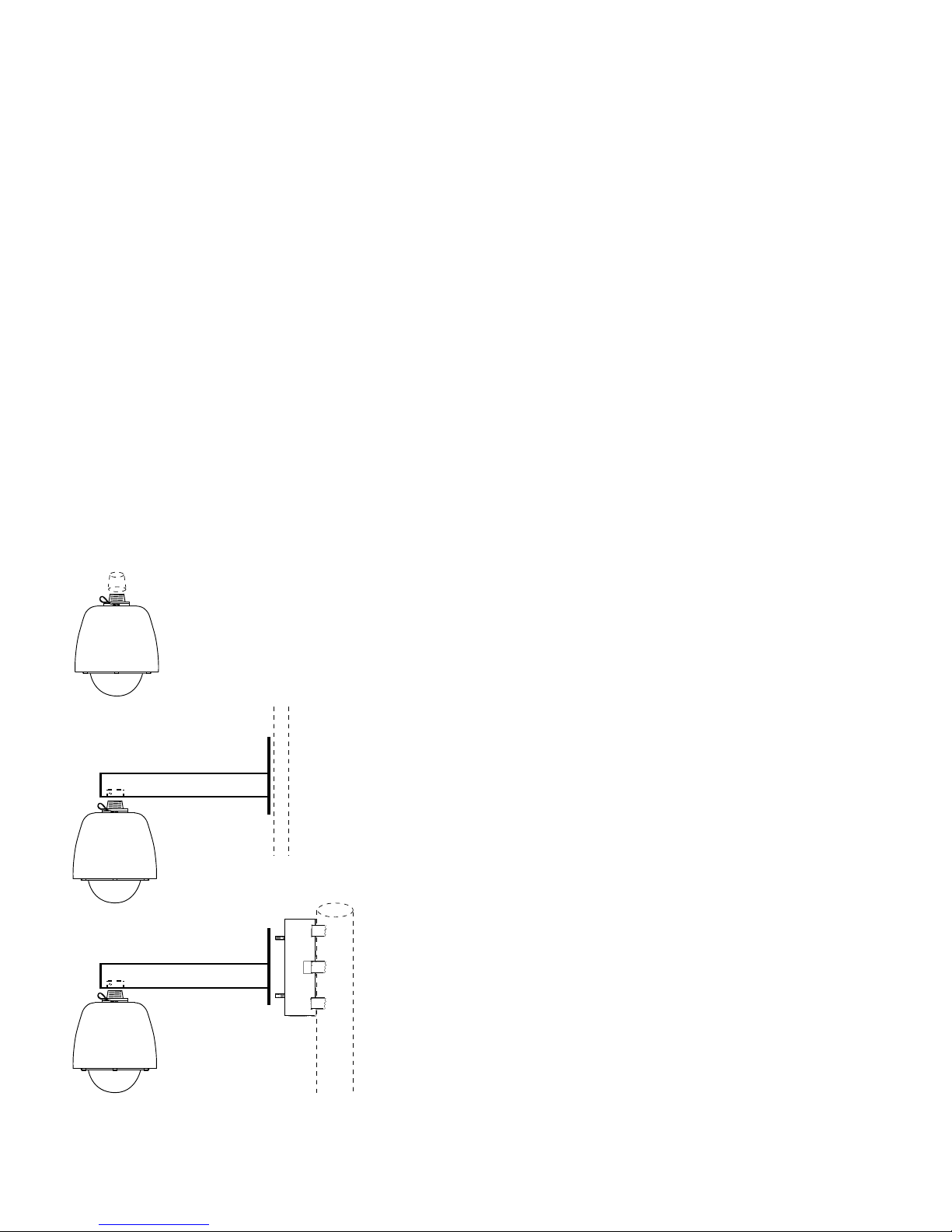
2.1.1 Basic Mounting Congurations
An iDome can typically be mounted in any one of
three mechanical congurations (gure 4):
2.1.1.1 Pendant Mount - The basic conguration.
The iDome hangs directly from a supplied 1.5inch female NPT (national pipe thread) support.
This support must provide for the connector of a
multiconductor cable to pass down through the 1.5inch pipe nipple for mating with the iDome.
2.1.1.2. Wall Mount - This mounting arrangement
requires an arm that bolts to the wall. The iDome
hangs from the end of this arm.
WALL MOUNT
POLE MOUNT
2.1.1.3. Pole Mount - This mounting arrangement
is similar to the Wall Mount — except that the
mounting arm attaches to a bracket fastened to a
pole instead of directly bolting to a wall.
Table 1 summarizes the major items supplied for
each of these three installation methods. Each of
these installations will be expanded upon in a later
sections.
2.1.2 Installation Checklist
Before starting the installation of an iDome the
following check lists should be read for an overview
of the process.
2.1.2.1 Test Bench Checkout - To check out
an iDome and set its address at a test bench
before taking it into the eld for installation, use the
following as a guideline:
Figure 4. Basic Mounting
Congurations
6
1. Mount the iDome to a test stand (gure 5).
This stand is also available with another
6X-1026E
3920 iDOME
INSTALLATION AND OPERATION
set of three legs that increases it from a
20-inch height to a 38 inch height.
2. Connect the test cable (gure 6) to the
connector at the top of the dome
3. Connect the other end of the cable to the
laptop. (Either a test cable with integral
RS-232 to RS-422 converter or separate
converter must be used. See gures 6
and 7.)
CAUTION
Step 4 assumes that the iDome operates from 115 V
ac power. If a 230 V ac iDome is to be operated from
this cable, a 115/230 adapter will have to be used.
This cable cannot be used with an iDome operating
from 24 V ac. Different connector pins are used.
4. Connect the power plug of this cable to
115 V ac — or for a 230 V ac iDome, remove the115 volt plug and replace it with
a 230 V ac plug. (This cable cannot be
used with 24 V ac iDomes.)
5. Connect a tv monitor to the cable. This
monitor must be terminated with 75
ohms. Monitors typically have a rear
panel switch to select either 75 ohms or
no termination (Only the end of the coax
cable can be terminated with 75 ohms.
Any other equipment connected on the
cable in a loop-through arrangement must
present a high impedance to the line.)
6. Install Win MPC software on the laptop.
(See section 2.11.1 for details about using
Win MPC.)
7. Establish the required communications
parameters
8. Set (or verify) the iDome address (When
installed in the system, each item of
equipment must have a unique address).
Place this address on the iDome with a
removable piece of masking tape.
Figure 5. Model 8540B Test Stand (23-inch height).
( Model 8540A -not shown- provides 38-inch height)
6X-1026E
7
INSTALLATION AND OPERATION
3920 iDOME
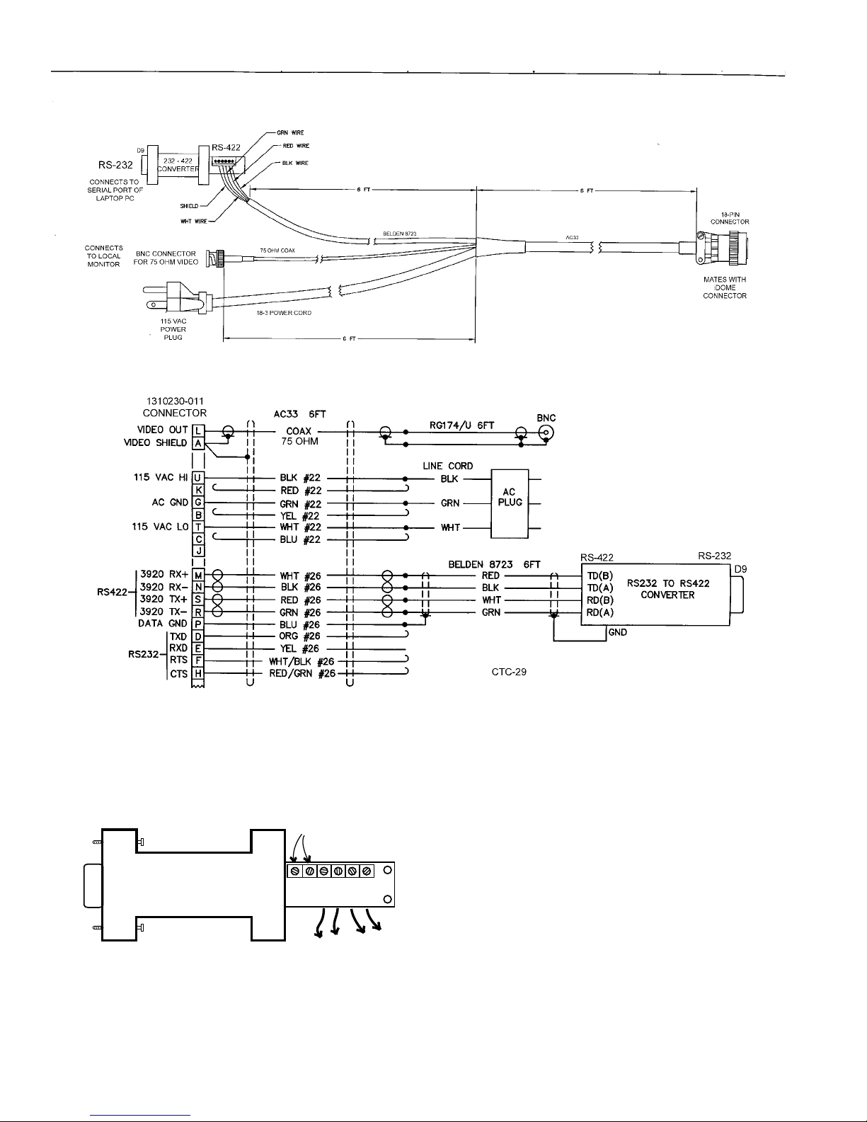
Figure 6. Type CTC-29 Cable , Test/Setup, Wiring Diagram
(Also Available from Cohu as P/N 3010100-001)
sales@bb-elec.com
www.bb-elec.com
D9
FEMALE
B & B
CONVERTER
232
Model 422PP9TB
B&B Electronics
707 Dayton Road
PO Box 1040
Ottawa IL 61350
+12V
422
Figure 7. Typical RS-232 to RS-422 Converter
8
MAY BE REQUIRED
SEE TEXT
RD(B)
RD(A)
TD(A)
GND
TD(B)
Tx-
Tx+
TO iDome
Rx+
Rx-
This converter changes the RS-232 output of a PC to RS-422 for
communications with an iDome during eld setup and testing.
A local PC with Win MPC software typically is used in this application.
If this converer is plugged into the RS-232 output from an F/0 converter, 12 V dc operating power will likely have to be applied to the
12 V dc terminal lugs. These F/O to RS-232 converters typically
do not have sufcient current on the handshake lines to power the
232/422 converter. This application of the 232/422 converter would
typically occur as part of a xed installation inside an equipment
cabinet located near an iDome. The 232/422 converter would be
part of a type CA-295G cable.
6X-1026E
3920 iDOME
INSTALLATION AND OPERATION
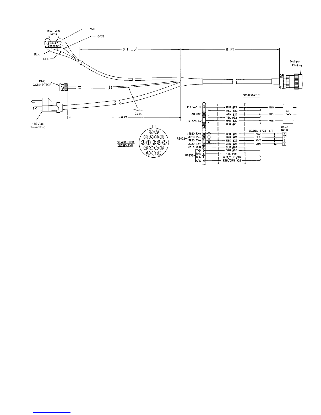
Figure 8. Type CTC-33 Cable , 9200 Control Panel Connection,
Test/Setup, Wiring Diagram
9. Verify proper operation of all the various
functions controllable through the Win
MPC menus.
10. Release the iDome for eld installation
after it has been determined all functions
are working.
2.1.2.2. Field Installation Procedure - Use the
following outline to become familiar with the steps
required to install an iDome at its eld location:
1. Route the cable to the mounting location
of the iDome.
2. Route the cable through any mounting
arms or brackets.
3. Remove the safety strap from the iDome
quick disconnect fastener
6. Wrap the connector with self sealing
waterproong tape to ensure a long-term
trouble free installation.
7. Attach the dome half of the quick disconnect to the half mounted to the arm or
other bracket. (If a particular orientation
is required be sure to mount it correctly
positioned.)
8. Attach the safety strap back to the other
half of the quick disconnect.
9. Connect the laptop to the iDome at the
junction box or equipment cabinet.
10. Verity (or set) the address and check all
operations.
11. Release the iDome for service.
4. Thread the nipple portion of the quick disconnect into the mounting bracket or arm.
5. Route the cable down through this nipple
and attach it to the iDome connector
6X-1026E
2.2 EQUIPMENT SUPPLIED
Depending on the mounting conguration, several
variations of equipment can be supplied. Refer to
table 1 for a list of the basic differences between
models as they relate to mounting arrangements.
9
INSTALLATION AND OPERATION
3920 iDOME
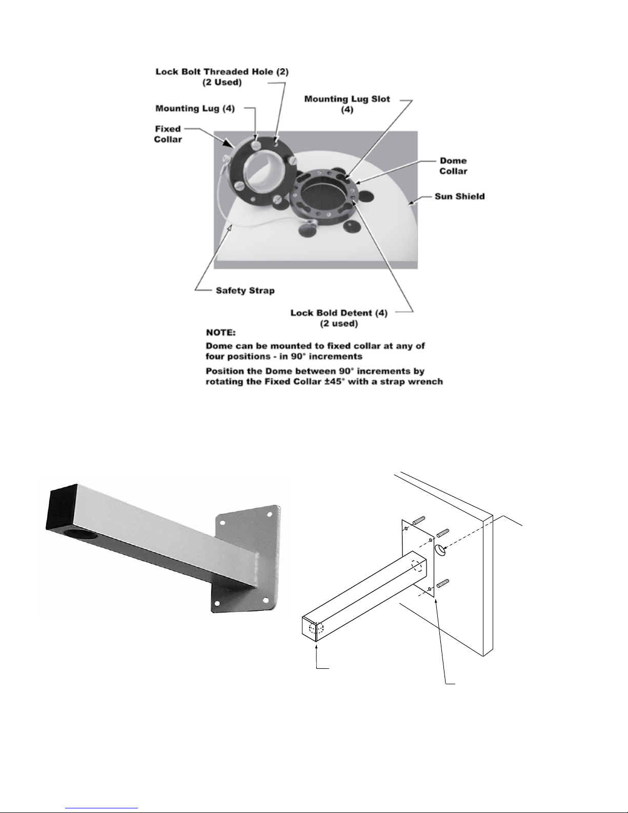
Figure 9. Quick Disconnect Assembly
ARM
1.5 NPT
for dome
quick disconnect
adapter
WALL
Route system
cable through
hole in wall
into Arm
Use weather-tight gasket
between Arm and wall
10
Figure 10. Wall Mount Arm
6X-1026E
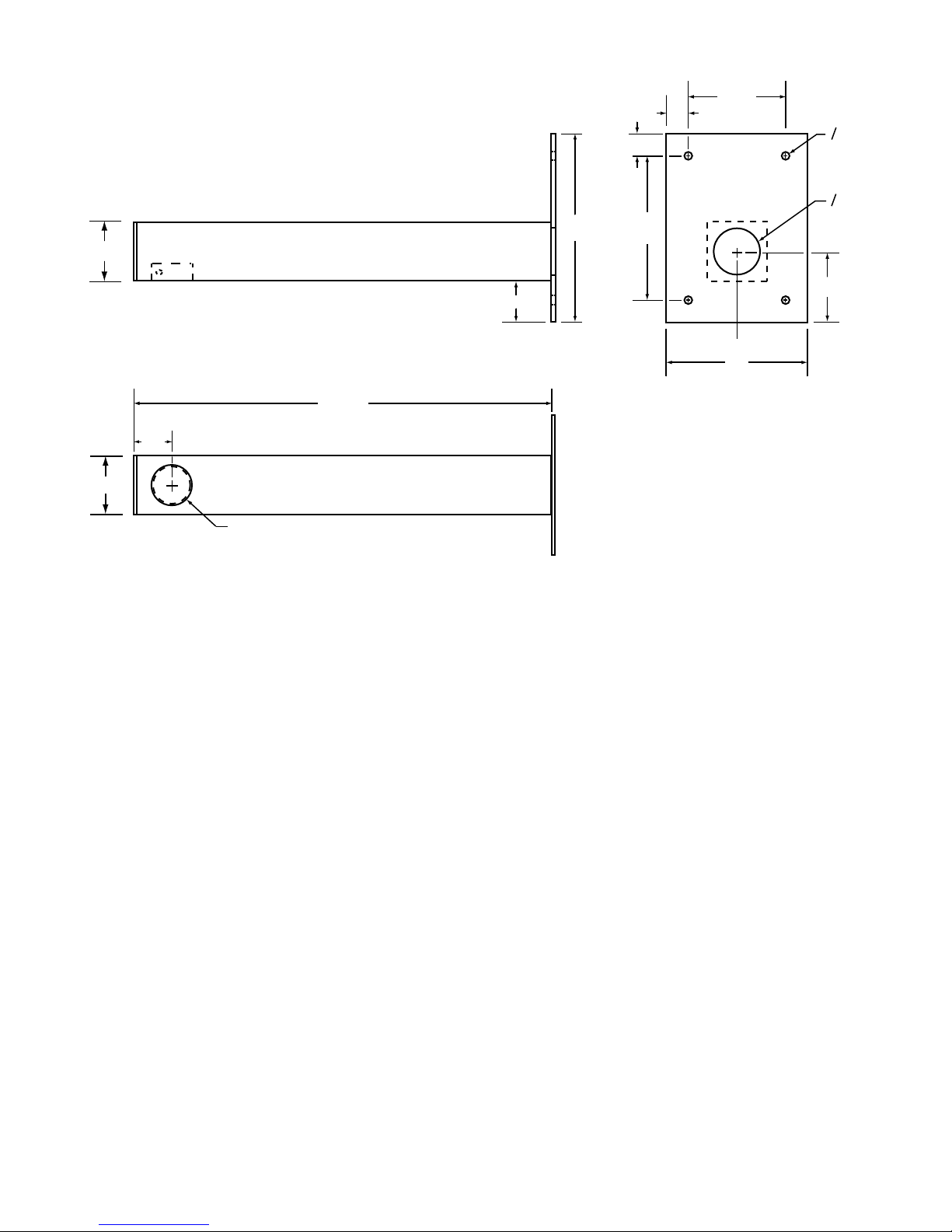
3920 iDOME
INSTALLATION AND OPERATION
2.0
2.0
UNLESS OTHERWISE NOTED ALL DIMENSIONS IN INCHES
17.75
1.75
1.5 NPT
1.75
8.0
0.75
4.50
0.75
O0.375
(TYP 4 PLACES)
O2.0
6.50
3.0
6.0
Figure 11. Arm Dimensions
2.2.1 PEND (Pendant Mount). See gure 9.
Pendant mounting is the most basic of the three
mounting arrangements. The top half of a quick-disconnect assembly is threaded into a site supplied
1.5-inch NPT mount.
2.2.2 WALL (Wall Mount). See gure 10.
With a wall mount the iDome hangs from the end
of an arm which is attached to a wall. Figure 11
gives dimensions of the arm and adapter plate.
This wall must not only have four mounting bolts but
also a hole centered between these bolts through
which the cable must pass. A weather-tight gasket
should be used between the arm and wall.
2.2.3 POLE (Pole Mount). See gure 12.
Mounting to a pole is similar to mounting to a wall.
For mounting to a pole, the four mounting bolts are
provided by a bracket. This bracket is attached to
the pole by stainless steel straps.
Cable routing when using a pole mount depends
upon the situation encountered. It can either be
directed down behind the pole bracket or, if arrangements have been made for this, into the pole. Junction boxes, drip loops, and weather proof integrity
of the connectors must be considered before starting the installation.
2.2.4 Connector Sealing
Even though the connector used with this camera
is designed to maintain a weather tight seal with its
mating system cable plug, it is recommended that
for additional protection against moisture in severe
conditions a sealing wrap be used on the connectors.
Coax Seal is the recommended product:
www.coaxseal.com
sales@coaxseal.com
United States: 1-800-241-8171
or International: 1-828-293-2222
6X-1026E
11

INSTALLATION AND OPERATION
3920 iDOME
This product is available from a variety of commercial supply houses, consumer stores, and in the
U.S. Government supply channels as GSA Schedule GS-07F-5739R
This product is a plastic tape-like material separated by a paper divider in its roll to prevent bonding
to itself before use. After this material is wrapped
around a connector, it forms a permanent weathertight seal.
The cable and connectors should be clean and dry
before wrapping with Coax-Seal.
Use a full wrap of this tape on the cable at the beginning. Then continue with a diagonal half overlap
wrap up to the iDome housing. Then add a full wrap
at the end of the coverage.
Squeeze together the wrapping so that it forms a
tight bond both to itself and the mating connectors.
The web site for Coax-Seal has complete informa-
tion about this product.
2.3 EQUIPMENT REQUIRED BUT NOT
SUPPLIED
Each installation will have unique requirements for
necessary cables, equipment, and miscellaneous
accessory items. This following is a list of the most
basic items required for installing at the site location
of the iDome. Some of these items can be ordered
with the iDome and thus would be provided in those
cases.
• 5/16-inch grade 316 stainless steel mounting hardware
• Cable, multiconductor, iDome to equipment cabinet
ARM
POLE MOUNT
DOME
12
Figure 12. Typical Pole Mount
6X-1026E
 Loading...