

Page 1

3610 SERIES
DSP COLOR CAMERA
TECHNICAL REFERENCE MANUAL
RS-232C SERIAL CONTROL
FCC
Figure 1. Machine Vision Color Camera
Technical Manual 6X-1042D
www.cohu-cameras.com/content/contactus
June 22, 2012
www.cohu-cameras.com
Page 2

3610 CAMERA
TECHNICAL REFERENCE
Table of Contents
1.0 General Description 3
1.1 Electrical Characteristics 3
1.1.1 Sensor Characteristics 3
1.2 Mechanical Characteristics 3
2.0 Installation 6
2.2 Equipment Supplied 6
2.3 Equipment Required But Not Supplied 7
2.4 Cabling Requirements 7
2.5 Power Requirements 7
2.6 Sync Requirements 10
2.6.1 H And V Drive Characteristics 10
2.7 Mounting Requirements 10
2.8 Cs- And C-Mount Adapters 10
2.9 Serial Control Input (Rs-232C) 10
2.10 Installation Procedure 12
3.0 Operation 13
3.1. Dsp3600 Gui Home Screen 13
3.1.1 Gamma Control 13
3.1.2 Freeze Image 13
3.1.3 Back Light Compensation (Blc) 14
3.1.3.1 Off (Fixed Weighted Average) 18
3.1.3.2 Automatic Weighted Average 18
3.1.3.3 Brighten Dark Areas 18
3.1.3.4 Darken Bright Areas 18
3.1.4 Save Button 18
3.1.5 Eeprom Button 19
3.2 Lens/Aperture (Lens Dialog) Window 19
3.2.1 Lens Area 19
3.2.2 Aperture Area 19
3.3 Set AE Windows (Set Weight) Window 19
4.0 Static Discharge Protection 21
5.0 Unpacking And Receiving Inspection 22
6.0 Preparation For Shipment And Storage 25
7.0 Warranty 27
NOTE: This equipment has been tested and found to comply with the limits for a Class A digital device, pursuant to Part
15 of the FCC Rules. These limits are designed to provide reasonable protection against harmful interference when the
equipment is operated in a commercial environment. This eqiupment generates, uses, and can radiate radio frequency
energy and, if not installed and used in accordance with the instruction manual, may cause harmful interference to radio
communications. Operation of this equipment in a residential area is likely to cause harmful interference in which case
the user will be required to correct the interference at his own expense.
CAUTION: Changes or modications to this device not
expressly approved by Cohu Electronics could void the
user’s authority to operate the device.
2
FCC STATEMENTS
This device complies with Part 15 of the FCC Rules. Operation is subject to the following two conditions: (1) this
device may not cause harmful interference, and (2) this
device must accept any interference received, including
interference that may cause undesired operation.
6X-1042D
Page 3

TECHNICAL REFERENCE
3610 CAMERA
1.0 GENERAL DESCRIPTION
This introduction briey describes overall
characteristics of the Camera (gure 1) related to
its installation and operation.
1.1 Electrical Characteristics
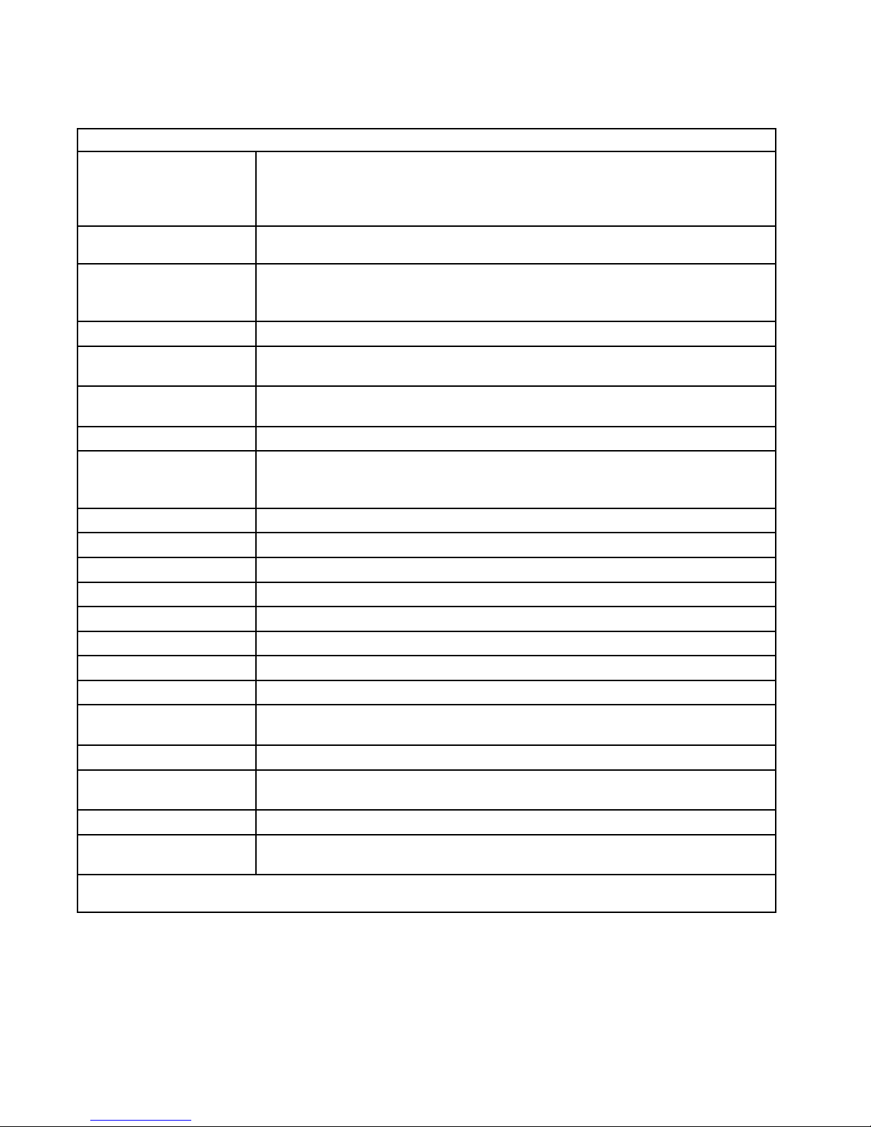
The 3610 Series provides a small, lightweight, highly sensitive machine vision CCD
Camera with all electrical connections via a single
rear panel connector.
Setup and control settings are implemented
by a graphical user interface (GUI) communicating through an RS-232C serial interface with the
Camera.
The Camera operates in either NTSC or PAL
format depending on the model. This Camera operates at an internal clock rate of 28.63636 MHz
(NTSC) or 28.375 MHz (PAL). Table 1 lists specications for this 3610 Camera.
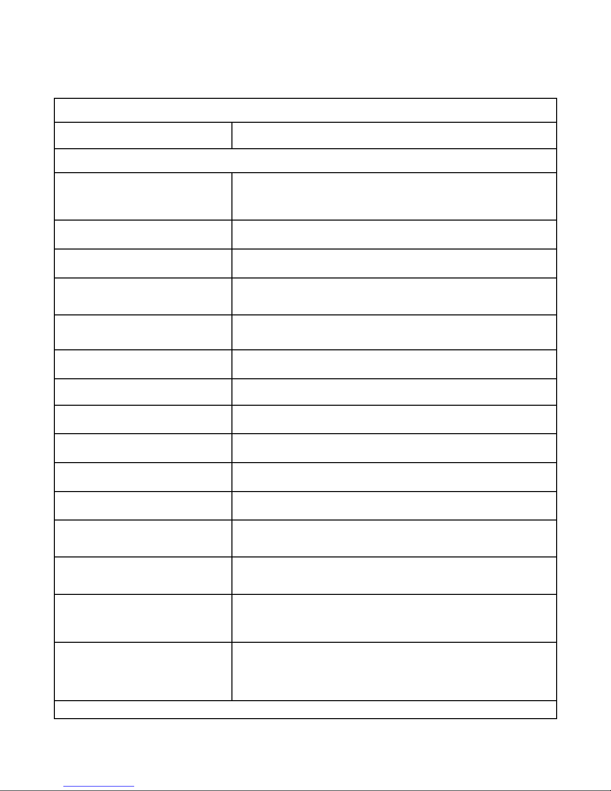
Table 2 is a list of major features of the Camera — primarily those associated with the GUI.
The Camera is available in two different
operating power congurations: 5 V dc and 12 V
dc. Only manual iris lenses can be used with the 5
V dc Camera. The 12 V dc Cameras are available
in three congurations: (1) an auto iris version
(2) a dc iris version or (3) a freeze frame version
— which requires the use of a manual iris lens.
Manual iris versions of the camera can be
optioned for horizontal and vertical drive inputs If
these inputs are not used the camera operates in
standard crystal sync reference mode.
1.1.1 Sensor Characteristics
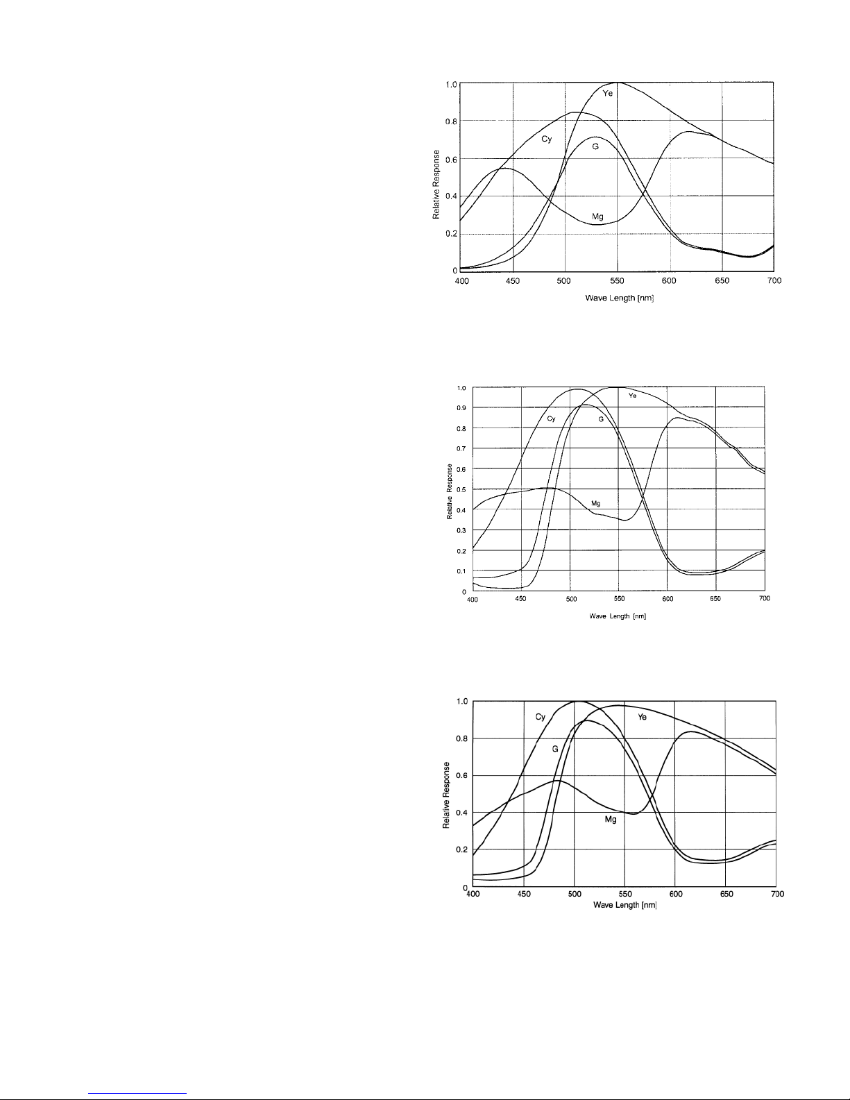
Figure 2 shows the relative response characteristic of the three sensor sizes available for this
camera. These characteristic curves apply to both
NTSC and PAL sensors. The curves show Cyan,
Green, Yellow and Magenta responses.
These graphs exclude both the lens characteristics and the light source characteristics.
Note however that the IR cut lter shown in
gure 3 will modify the overall response of the
Camera to light. This low pass lter starts block-
ing light above about 500 nanometers and at 600
nm passes only about 50 percent. Rolling off the
response at these longer wavelengths minimizes
the effect of infrared on the color response of the
Camera.
1.2 Mechanical Characteristics
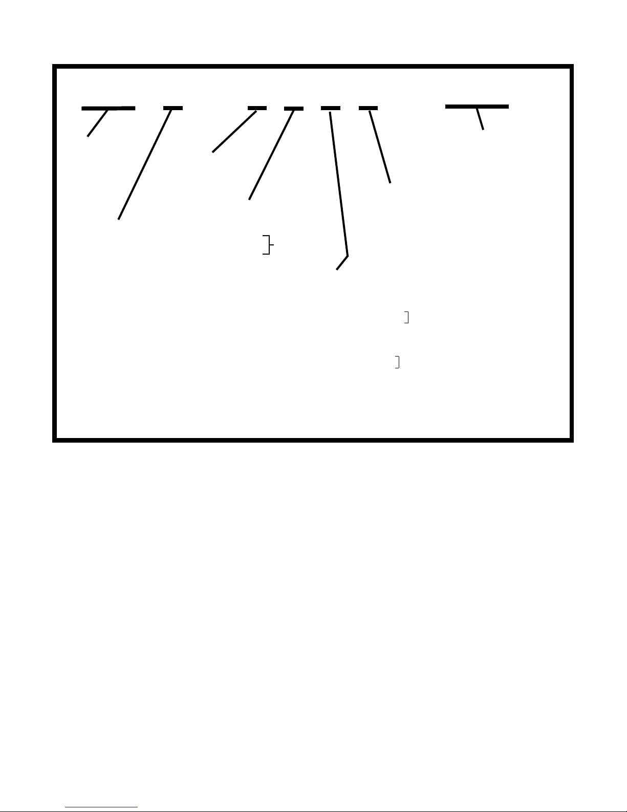
A model number interpretation diagram ap-
pears in gure 4. This diagram shows the various
basic congurations of the Camera.
Dimensions for the Camera are shown in g-
ure 5. Figure 6 is a detailed dimensional illustration for the optional mounting block that provides
threaded 1/4-20 mounting holes. The Camera
consists of a main body casting and front casting
assembly.
Interconnections are via a 12-pin connector
located on the rear panel.
An adjustable CS-mount adapter threads
onto the front of the casting. It is secured from
turning by a nylon tipped hex-socket head setscrew.
The Camera can be mounted at any of three
places on its body:
1. By the CS mount directly to a microscope or
other similar device
2. By the top of the case — either with or without
the optional mounting block
3. By the bottom of the case — either with or
without the optional mounting block
Directly mounting to the top or bottom of the
housing requires removal of the two black button
head screws holding the outer housing cover in
place at that location (top or bottom). The optional Accessory Kit contains the mounting block
and a pair of 2-56 × 3/8 stainless steel screws to
attach it to the Camera.
If the Camera is to be mounted directly without use of the optional mounting block, a pair of
2-56 stainless steel screws of the required length
would have to be acquired. These are not supplied.
6X-1042D
3
Page 4
3610 CAMERA
TECHNICAL REFERENCE
Table 1. Specications
ELECTRICAL
Interline transfer color CCD operating in eld mode
Format
Pixels 768 × 494 NTSC; 752 × 582 PAL
Pixel Cell Size
Resolution NTSC: 460 H × 350 TV lines; PAL: 450 X 415
Internal Clock
Sync
Frame Rate 30 fps (NTSC); 25 fps (PAL)
Sensitivity, Faceplate
White Balance Auto or manual white balance, 2500 to 9500 K
1/2 inch (6.45 × 4.84 mm)
1/3 inch (4.44 x 3.33 mm)
1/4 inch (3.33 × 2.5 mm)
1/2 inch: 8.40 (H) × 9.80 (V) µm NTSC ; 8.60 (H) × 8.30 (V) µm PAL
1/3 inch: 6.35 (H) × 7.40 (V) µm NTSC ; 6.50 (H) × 6.25 (V) µm PAL
1/4 inch: 4.75 (H) x 5.55 (V) µm NTSC ; 4.85 (H) x 4.65 (V) µm PAL
28.63636 MHz (NTSC)
28.375 MHz (PAL)
Internal crystal; or,
H & V drive, revert to crystal; (composite sync special order)
1/2 inch: 3 lux with full video, minimum gain
1/3 inch: 4 lux with full video, minimum gain
1/4 inch: 8.5 lux with full video, minimum gain
Gamma Choices of 10 gamma curves (8 power function, 2 linear)
Gain 0 to 32 dB gain control — either agc or menu selected manual adjustment
Shutter 1/60 (1/50 PAL) to 1/50,000 s, in nine steps (menu selected)
S/N 48 dB max; 22 dB S/N with 32 dB gain
Spectral Responses See gure 2
Integration 2 to 510 elds available using menu selection
Video Output Simultaneous composite and S-video (NTSC or PAL)
Lens Control
Serial Communications RS-232C, 19,200 baud (xed)
Power Input
Power Consumption 5 V: 2.5 W (500 mA) or 12 V: 4.2 W (350 mA)
Regulatory
5 volt camera: manual iris only
12 volt camera: manual iris, auto iris, or dc iris
5 V dc ±10 % or
12 V dc ±10 % (depending on model)
CE CISPRII class A plus EN61000-4 -3, EN61000-4 -6, EN61000-4 -8 interference immunity test
Continued on next page
4
6X-1042D
Page 5

TECHNICAL REFERENCE
3610 CAMERA
Table 1. Specications (continued)
MECHANICAL
Dimensions 1 x 1 x 3 inch, less lens (see gure 5)
Weight 2.9 oz (82 g), less lens
Two 1/4-20 screws (accepts 0.200 deep screw) top or bottom mounting block,
Camera Mount
Lens Mount
Connectors Single 12-pin Hirose HR10A-10R-12PC
Temperature
Vibration, less lens Per MIL-STD-810(E), Method 514.4, categories 1, 4, 5, 8, 9, 10
Shock, less lens No damage to 30 g’s, 11 ms duration, no crash hazard to 75 g’s, 11 ms duration
or direct to top or bottom of camera body with two 2-56 inch screws,
or via CS mount direct to microscope or similar device
CS-mount, adjustable, or C-mount using 5 mm extension adapter
Lens can be moved up to 3-inch from main electronics
-20 to 70 °C operating
-30 to 85 °C non operating
end
6X-1042D
5
Page 6
3610 CAMERA
2.0 INSTALLATION
In addition to the actual installation requirements, this section covers a number of other items
including proper shipping and handling of the
Camera.
2.2 Equipment Supplied
The equipment supplied depends on what
has been ordered. In its most basic form only the
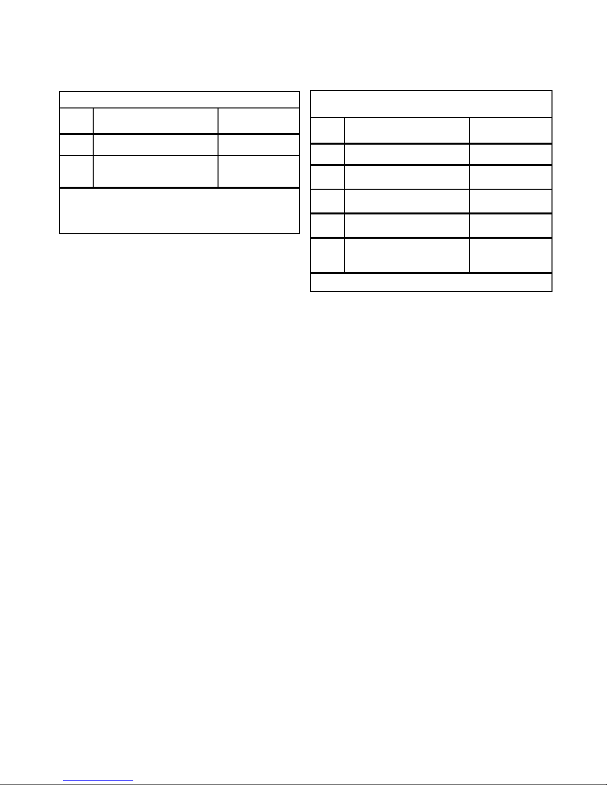
following would be supplied (table 3):
TECHNICAL REFERENCE
1. The Camera itself (either NTSC or PAL version)
2. A CS-mount adapter, 0.335 width
3. Locking setscrew for adapter (4-40 x 5/32)
4. Graphical User Interface (GUI) available either
with the Camera on disk or downloaded from:
www.cohu-cameras.com/tech/tech.htm
The following items are provided if the option-
al accessory kit has been ordered (table 4):
1. Wrench, hex key (Allen) “L” type wrench, 1/16inch
2. 5 mm extender ring for use with C-mount
lenses
3. Mounting block (provides two 1/4-20 threaded
holes)
4. Screw, athead, 2-56 × 3/8 stainless (2 each)
1/4-inch Sensor
1/3-inch Sensor
5. Connector, plug, cable, 12-pin (mates with
rear panel connector)
The following items will also be supplied if
they were ordered:
1. Lens, for sensor imaging (for either 1/3-, 1/4-,
or 1/2-inch sensor), depending on version of
Camera
2. Power supply — depending on the version of
Camera:
6
1/2-inch Sensor
Figure 2. Sensor Response
Characteristics
6X-1042D
Page 7

TECHNICAL REFERENCE
a. 5 V dc, 500 mA power supply (Cohu type
8470-5) or
b. 12 V dc, 350 mA power supply (Cohu type
8368-4)
Note that special-order Cameras and Camer-
as modied for special purposes may be shipped
with other items. The above listing are the basic
items for typical applications.
Table 3 lists the basic items supplied with a
Camera. Table 4 lists items supplied in an optional
accessory kit.
2.3 Equipment Required but Not
Supplied
If the following items were not ordered with
the Camera these will be required to make it operational:
3610 CAMERA
Figure 3. IR Cut Filter Response
Characteristics
1. CS- or C-mount lens suitable for the sensor
format/size in Camera
2. Power supply, 5 V dc, 500 mA output or 12 V
dc, 350 mA
3. Cable. Refer to one of these test cables as an
example for the construction of an interconnection cable to be used with the Camera:
a. See gure 8 for use with a 5 V dc (manual
iris) versions of Camera. This cable shows
connections for the H and V drive option.
b. See gure 9 for use with auto iris or dc
iris version of Camera (12 V dc operating
power).
c. See gure 10 for use with a 12 V dc Cam-
era optioned for freeze frame operation.
(Requires use of a manual iris lens.) This
cable shows connections for the H and V
drive option.
4. 1/4-20 mounting bolt(s) of the proper length if
the mounting block is to be used.
2.4 Cabling Requirements
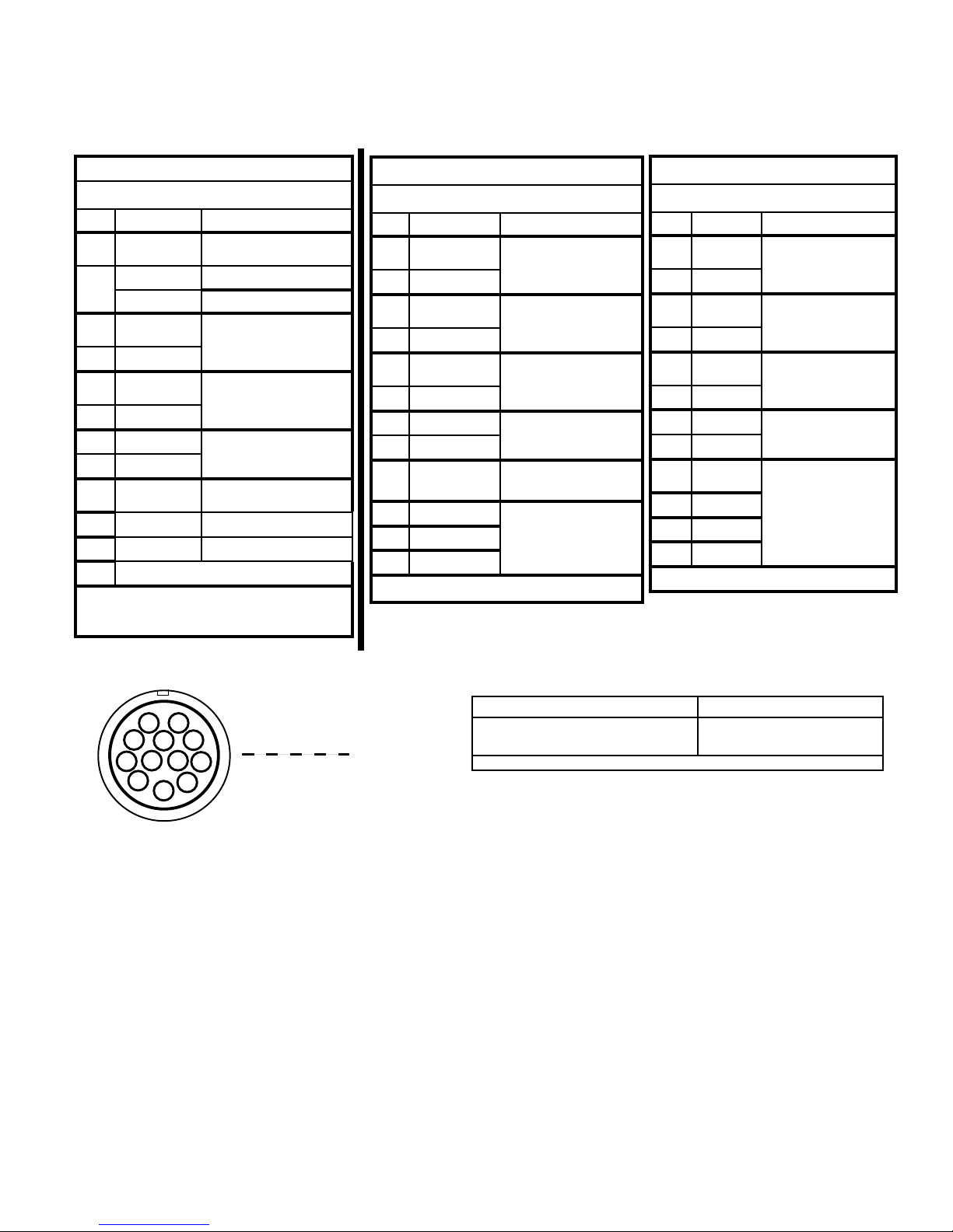
A single 12-pin connector (gure 7) on the
rear panel provides all electrical connections to
the Camera. Table 6 lists the mating cable plug for
this rear panel connector. Use this plug to construct the cable for operating the camera.
Several test cables are shown in this manual.
They can be used as an example for wiring the
operating cable for a Camera.
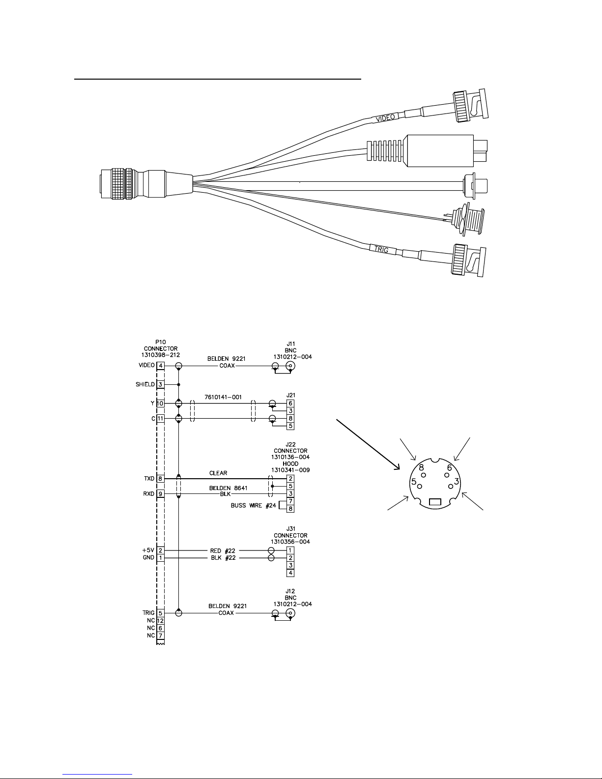
Figure 8 shows the wiring arrangement for a
5 V dc (manual iris only) version of the Camera.
This cable provides for all operating capabilities of
a 5 V dc Camera.
A 12 V dc version of the Camera may require
a cable wired to either of two congurations. One
is for use when the Camera is internally cong-
ured for use with either an auto iris lens or a dc iris
lens. The other is for use when a 12 V dc Camera
is internally congured for freeze frame operation,
and/or external horizontal/vertical drive options.
1. Figure 9 shows the cable for use when a 12
V dc version of the Camera is congured for
either an auto iris lens or a dc iris lens.
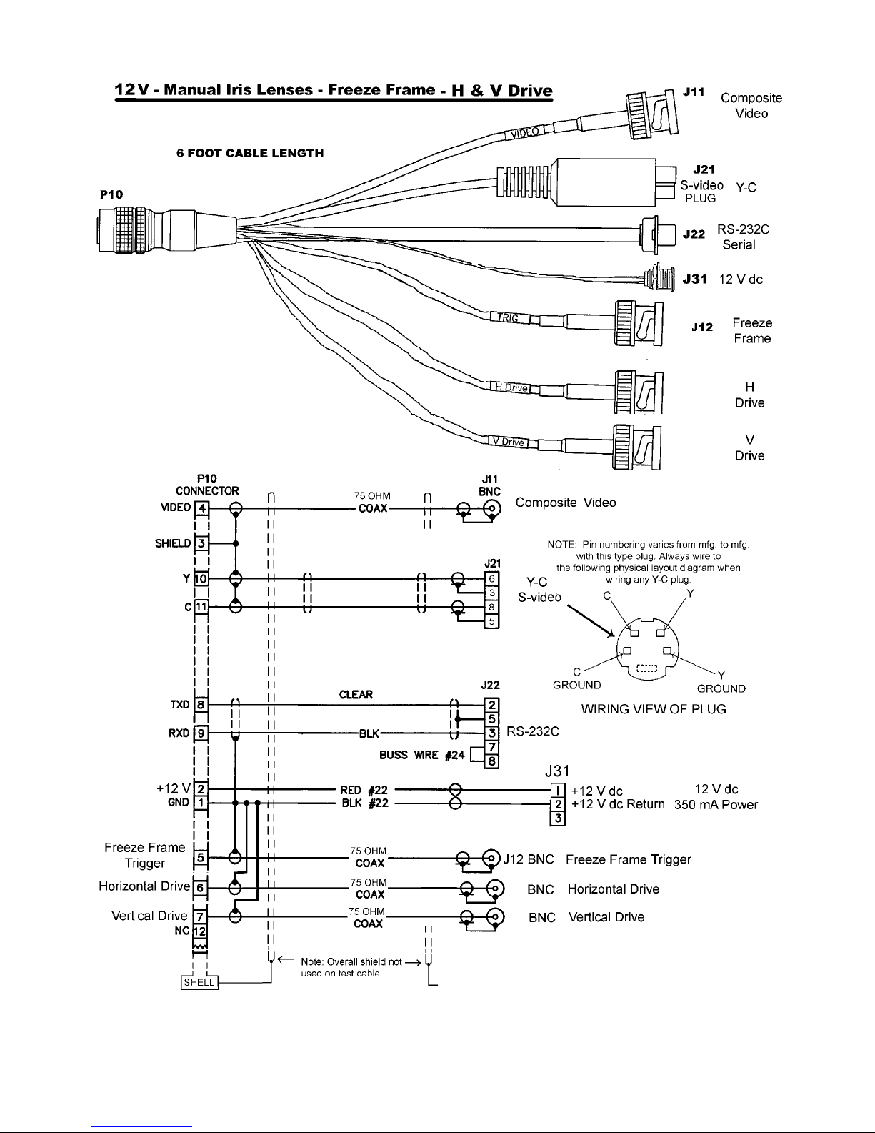
2. Figure 10 shows cable wiring for use when
a 12 V dc Camera is internally congured for
either freeze frame operation or H and V drive.
Only a manual iris lens can be used when the
Camera is congured for either freeze frame
operation or H and V drive.
6X-1042D
7
Page 8
3610 CAMERA
TECHNICAL REFERENCE
361 x — x x x x — ××××
SERIES
CCD
CAMERA
1 Internal crystal
2 H&V drive
POWER
1 5 V dc Power
2 12 V dc Power
* Revert to crystal 12 V dc Camera only
** Trigger designates the freeze frame mode
discussed in this manual
NOTE: Composite sync input is a special
order feature. It does not appear in this
model index diagram.
SYNC
*
IRIS
0 Manual Iris & Trigger
1 Auto Iris
4 Dc Iris
ACCESORIES
0 None
1 Test cable
2 Accessory kit
3 Test cable & accessory kit
12 Vdc
cameras
only
*
*
SENSOR
2 1/2-inch NTSC, S-video
3 1/3-inch NTSC, S-video
4 1/4-inch NTSC, S-video
5 1/2-inch PAL, S-video
6 1/3-inch PAL, S-video
7 1/4-inch PAL, S-video
12 V dc Camera only
12 V dc Camera only
LENS
0000 None
(Manual iris,
auto iris &
dc iris lenses
available)
This is a model number interpretation diagram. It should be used only for determining
the features of an existing model number — such as that labeled on a Camera.
Figure 4. Model Number Interpretation Diagram
Note that the pins 5, 6, 7, & 12 for a 12 V
dc Camera can be internally wired for any one of
three functions.
1. Auto iris lens
2. Dc iris lens
3. Freeze frame operation together with
H and V drive
The model number designates these differences for 12 V dc Cameras. See the
of gure 4.
IRIS section
2.5 Power Requirements
The Camera is available in two different
power congurations:
1. 5 V dc ±10% 500 mA (2.5 watt) power
2. 12 V dc ±10%, 350 mA (4.2 watt). Auto iris and
dc iris versions of the Camera are available
only in the 12 V dc version
8
6X-1042D
Page 9

TECHNICAL REFERENCE
*
Optical path includes 0.031 (0.8) thick BK-7 flat glass and 0.213 (5.4) thick multilayer
quartz optical low-pass filter. Actual image plane is 0.81 (2.1) behind effective image plane.
3610 CAMERA
Locking Setscrew
(Nominal Position)
O
1.00
(25.40)
1.00
(25.40)
Adjustable CS-mount
Optical and Mechanical
Centerlines Same
Dimensions in inch and (mm)
(2 place)
Use 2-56 x 3/8 flathead stainless steel screw
Optional Mounting Block
1.125
(28.57)
0.335
(8.51)
Nominal
0.3175 (8.064)
0.492
(12.5)
0.55
(14)
Effective Image Plane
3.00 (76.2)
2.635
(66.93)
1.500 (38.10)
*
Mounting block
can fasten
top or bottom
0.50 (12.7)
1/4-20
(2 Place)
(0.20 max depth)
0.20
(5.1)
Figure 5. Dimensions, Model 3610 Camera
Figure 6. Dimensions, Optional Mounting Block
6X-1042D
9
Page 10

3610 CAMERA
TECHNICAL REFERENCE
2.6 Sync Requirements
A standard camera is available in two differ-
ent versions related to sync:
1. Internal Crystal
2. Horizontal drive and vertical drive (12VDC
Camera only)
A camera optioned for either auto iris or dc
iris automatically has the Internal Crystal option.
Only a camera with the manual iris option
can also have the horizontal and vertical drive
option. Likewise a camera having the horizontal
and vertical drive option can only be a manual iris
camera.
H and V drive reverts to the internal crystal if
either of the inputs or both inputs are removed.
As a special order, the camera is also available with genlock. With genlock, the external sync
reference is applied to a single input on the rear
panel. This input must have both horizontal and
vertical pulses ( composite sync) and they can be
combined with video (composite video). Additional
details about the genlock feature is not covered in
this manual.
2.6.1 H and V Drive Characteristics
These are 75 ohm internally terminated
inputs. It is best to use 75 ohm coax especially
for longer runs. They trigger on negative edges at
standard TTL levels.
2.7 Mounting Requirements
The dimensions shown in gures 5 and 6
illustrate all relevant characteristics related to
mounting the Camera. Note that the CS-mount
adapter is adjustable. The dimension to the front
shoulder of the adapter is a nominal dimension.
Also note that the 1/4-20 threaded holes in the
bottom of the optional mounting adapter block are
meant to accept not more than 0.200-inch depth
from the mounting screws. A screw will bottom
out if an attempt is made to thread it deeper than
0.200 inch.
2.8 CS- and C-mount Adapters
Lenses must be suitable for use with size of
the sensor installed in the Camera (1/4-, 1/3-, or
1/2-inch). The front of the Camera body is tted
with an adjustable CS-mount adapter. It can be
rotated on its threads for back focus distance by
loosening a hex-socket head setscrew. (Figures 5
and 6 illustrate this setscrew at one location, but
since the CS mount rotates, it can appear in any
position.)
If a C-mount lens is to be used with the
Camera a 5 mm extender ring (in the optional
Accessory Kit) must be threaded onto the front of
the CS mount. This ring provide the proper back
focus distance for a C-mount lenses.
2.9 Serial Control Input (RS-232C)
Pins 8 and 9 on the rear panel connector
provide RS-232C serial communications (19,200
baud) for control of internal Camera functions.
The three parts of table 5 lists all 12 pin functions
on the connector for various congurations of the
camera.
2.10 Installation Procedure
Installing the Camera is straightforward. It is
only necessary to mount the Camera to a suitable
base, attach the lens, attach the rear panel connector and apply power. This assumes the other
end of the cable is properly connected to a source
of power, a tv monitor, and any other required
equipment.
Figures 8 is an example cable diagram of a
test cable for use with the 5 V dc version of the
Camera. Only manual iris lenses can be used
with this Camera. The H & V drive leads are required only for a camera with this option.
Figures 9 and 10 are example wiring diagrams illustrating test cables available for use with
the 12 V dc version of the Camera.
Figure 9 is for use with either an auto iris
lens or a dc iris lens — depending on how the
Camera is internally congured.
10
6X-1042D
Page 11
TECHNICAL REFERENCE
3610 CAMERA
Table 2. Capabilities
AUTOMATIC OPERATION
Standard Feature
SERIAL REMOTE CONTROL FUNCTIONS
Programmable Aperture Correction
Complex Gamma Curve Constructions
2-D Mirroring
Programmable backlight Compensation
involving window masking and histograms
Windowed Auto Exposure
Electronic Pan & Tilt
Negative Y and/or C
Monochrome
Camera can be set up for unattended operation with no operator input
Modies high frequency response in camera circuits to enhance black-white
transitions in the scenes. Has the effect of making scenes look “sharper.” Can
be implemented for horizontal alone, vertical alone, or for both horizontal and
vertical simultaneously
Makes it possible to taylor a gamma curve for the types of scenes typically
viewed
Allows for horizontal and vertical to be independently reversed left-right and
top-bottom
Makes it possible to minimize the effect of bright areas of the scene outside the
areas of interest either by masking out those areas or by applying an integration
effect to a histogram of the scene brightness levels
Makes it possible to window (select) an area of the scene upon which the auto
exposure circuits will operate.
When zoomed in from a full frame view, makes it possible to electronically move
right/left (panning), up/down (tilt), or rotated (angle viewed changes)
Luminance (Y) can be reversed to make an negative image and/or color (C)
can be reversed or removed.
Monochrome removes “C” (color) information from the video output so only the
luminance information is present
Freeze
Programmable Blemish Correction
Presets Selections in the various GUI menus can be saved to a preset for easy recall
Auto/manual gain
Shutter
Integration
White Balance
Freeze mode captures the current image of the scene and continues to provide
it as video output until this mode is deselected.
Any pixel areas of the scene can be modied to the desired response and
stored as a permanent characteristic for that area
Gain control can be set for either of two modes: 1. Automatic control by the
camera to maintain video output or 2. Manual gain control mode through menu
selections with the GUI
The sensor can be made to collect light for less than the normal time (“Normal”
is 1/60 for NTSC or 1/50 for PAL). Nine selections are available up to 1/50,000
sec. Frames continues at the normal rate while shuttering.
The sensor can be made to collect light for enhanced sensitivity by menu
selection of integration times from 2 elds to 510 elds. The Camera continues
to output at its normal frame rate during this integration time but with the last
integrated eld until the next integrated eld is available.
Three white balance modes are available. One is automatic white balance with
the camera circuits maintaining proper white balance. The second choice is
moving sliders on a GUI screen to change the white balance curves manually.
The third choice is the User mode in which it is possible to independently move
sliders on the red and blue response curves.
Continued
6X-1042D
11
Page 12
3610 CAMERA
Auto iris, dc iris, manual iris lens selections
Horizontal and vertical drive
TECHNICAL REFERENCE
Table 2. Capabilities (continued)
OTHER CAPABILITIES
All versions of the Camera can be used with a manual iris lens. A 12 V dc version
of the Camera can also be optioned for use with an auto iris lens or a dc iris lens
— or it can be optioned for the freeze frame mode of operation. Freeze frame
precludes use of an auto or dc iris lens.
Manual iris versions of the camera can be optioned for H & V drive inputs. Camera
operates in crystal mode if H and V drive are not provided (revert to crystal).
Figure 10 is for use when the Camera is in-
ternally congured for freeze frame operation or H
& V drive — in which case only a manual iris lens
can be used.
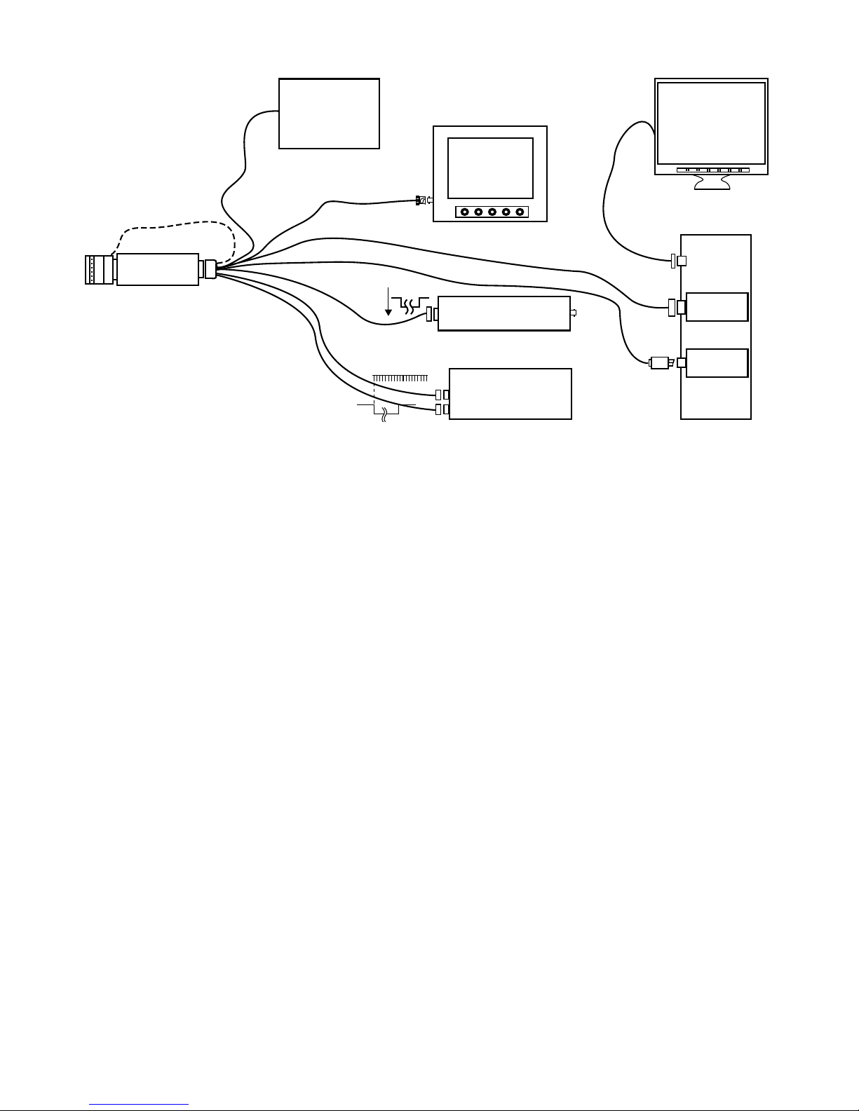
These diagrams show composite video
connected to a viewing monitor and the S-video
connected to a frame grabber in the PC. Either
video output can be used for the scene monitor
and frame grabber if they are capable of accepting
those inputs.
Freeze frame can also be implemented
through the serial link by using the GUI interface
on the PC. When the Camera is put into the freeze
mode, it stores the current scene and continues to
output that scene until the Camera is taken out of
the freeze frame mode.
As a minimum, the following must be connected:
1. Operating power: either 5 V dc, 500 mA, or 12
V dc, 350 mA, depending on the version of the
Camera
2. RS-232C data communications with a PC running the test/setup GUI software
3. Either of these two video monitoring methods:
a. NTSC or PAL output on pin 4 of the rear
panel connector
b. The S-video outputs (Y on pin 10 and C on
pin 11)
Additionally, the following connections can be
made — depending on the requirements:
4. The freeze frame input TRIG (pin 5). This is
only for the manual iris versions of the Camera
5. The H & V drive connections if the camera has
this option. Only a manual iris lens version can
have this option. (12VDC Camera only)
6. The unused video output may also be used.
These outputs appear simultaneously.
7. An auto iris lens or a dc iris lens, depending on
which type lens a 12 V dc version Camera is
internally congured for — unless, of course, it
is congured for freeze frame operation.
3.0 OPERATION
After the Camera is installed, the actual operation of the Camera is controlled by the related
frame grabber and image processing software.
The iris on a manual lens may have to be
opened and closed in response to changing scene
lighting conditions. The lens may also require
refocusing from time to time if the image changes
position, but otherwise there is no other attention
required for the Camera.
Camera functions are primarily controlled by
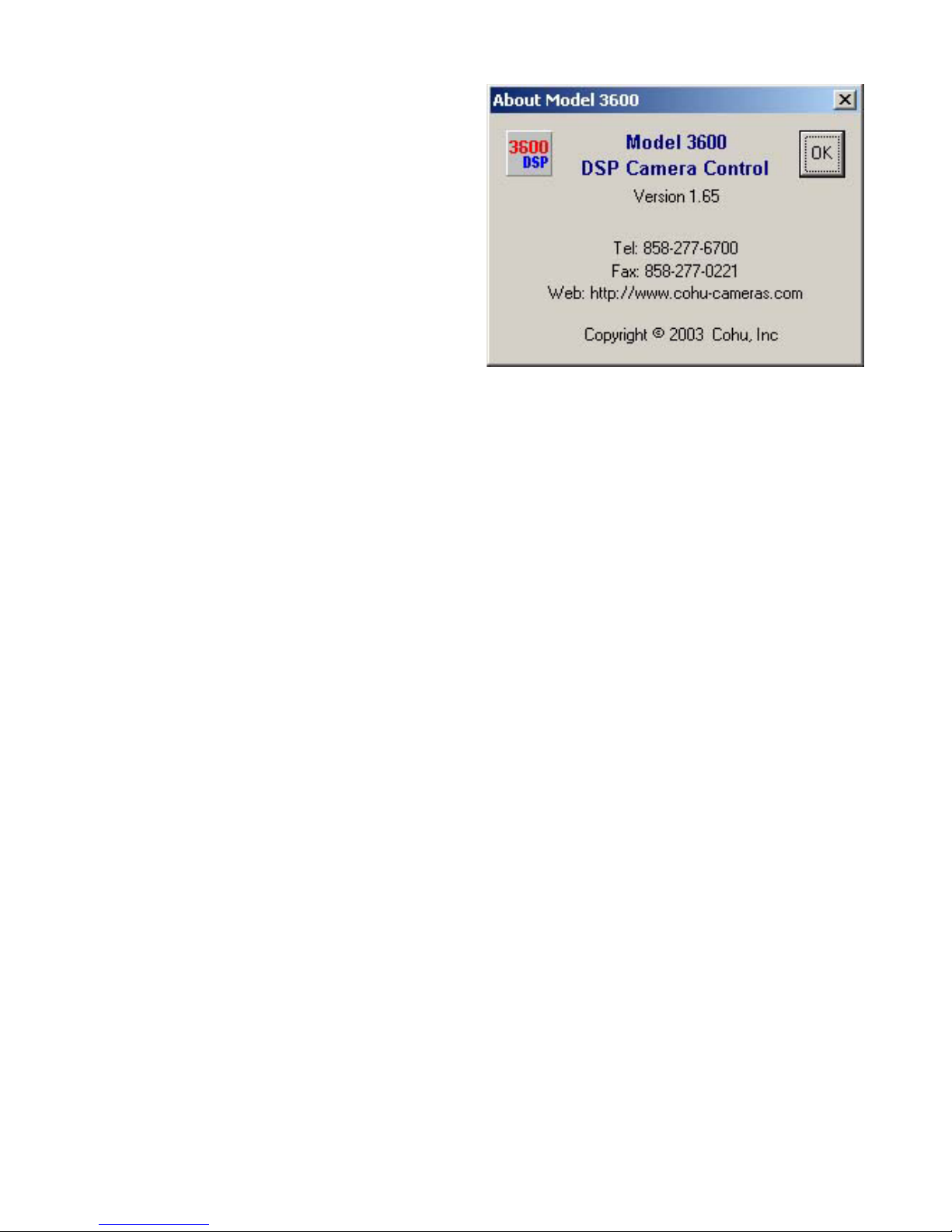
the GUI interface running on a PC. Figure 12 is
the “about” window for the current version of this
software.
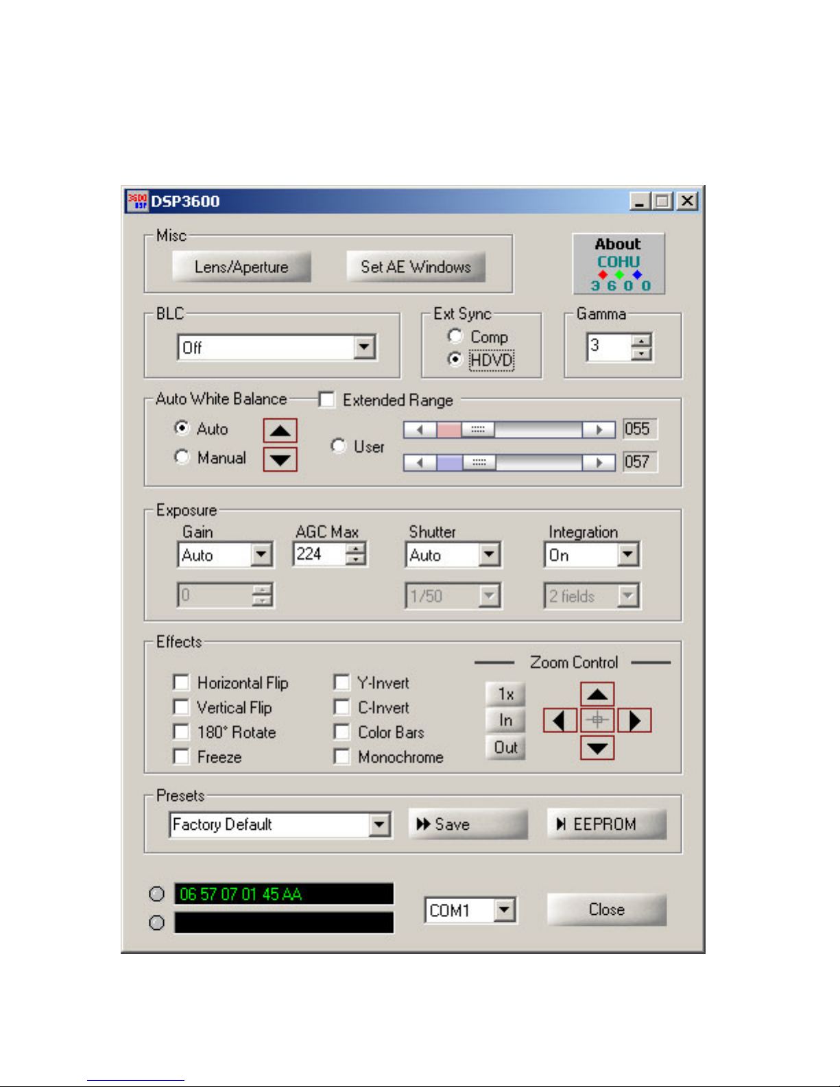
Figure 13 shows the opening “home” window
of the 3610 Graphical User Interface (GUI). Most
control functions are performed from this window,
but two other windows accessible from the Misc
area also perform important functions:
12
6X-1042D
Page 13
TECHNICAL REFERENCE
3610 CAMERA
Table 3. Items Supplied
ITEMS SUPPLIED
ITEM DESCRIPTION PART NUMBER
1 CS-mount, 0.335 wide 8359208-001
2
Note: These items are typically mounted on the Camera
when it is shipped. An optional Accessory Kit is available
to supply additional items that may be useful in some
installation.
3.1. DSP3600 GUI Home Screen
Figure 13 (DSP3600) is the primary control
window where all the various functions are accessible. Clicking various buttons in this window
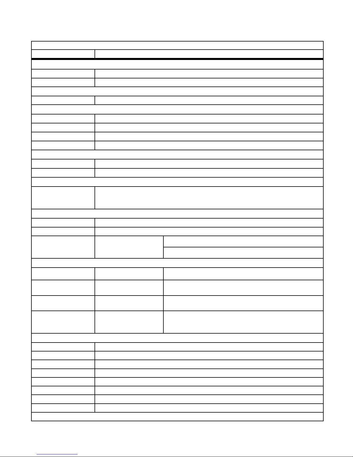
causes drop down menus to appear. Table 7 lists
the various functions and gives a brief description.
Any selection of settings in the GUI can be
stored to one of the presets. Just select the desired preset number (Preset 1 to Preset 10), then
click Save. If it is desired to make those (or some
other group of selections) the internal default of
the Camera, just click on the EEPROM button.
Those settings are then stored in Camera memory and remain as the Camera default settings
until other selections are stored by clicking on the
EEPROM button again. The GUI will remember
the factory default it is necessary to return to reset
conditions.
If a frame grabber is used to capture the
video output from a Camera, it too will have a GUI
interface for manipulation of Camera features.
Set Screw, nylon tipped,
stainless, 4-40 x 5/32
1. Lens/Aperture opens the Lens Dialog window
(g. 14)
2. Set AE Window opens the Set Weight window
(g. 15)
2010258-005
Table 4. Optional Accessory Kit
KIT 8478-3 (12 Volt Cameras)
ITEM DESCRIPTION PART NUMBER
1 Wrench, hex key, 1/16 inch 9710010-009
2
3
4
5
3.1.1 Gamma Control
The gamma selections of the GUI make
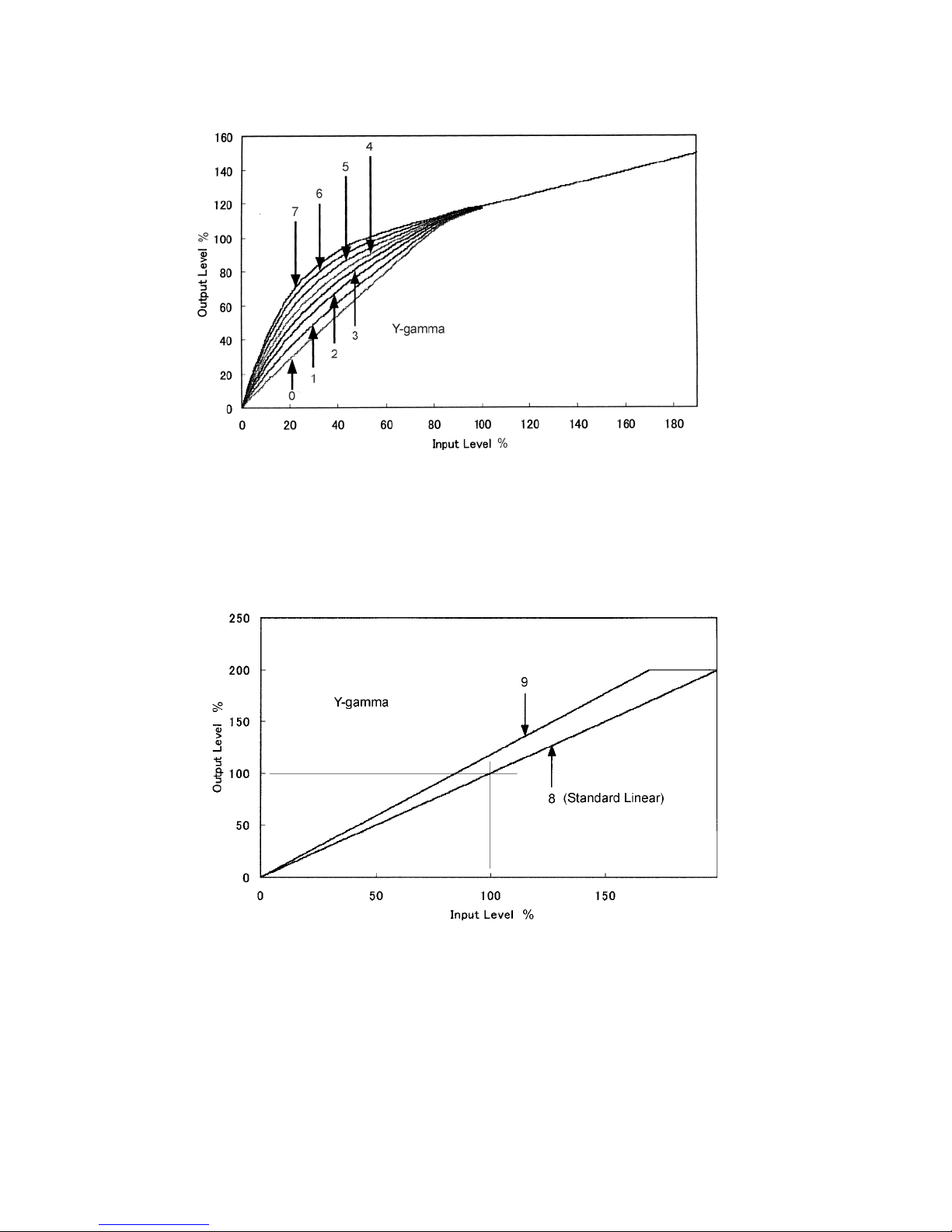
changes to the luminance (black-white) characteristic (Y-gamma). It can be set to any of 10
response curves.
Selections 0 through 7 are an increasingly
nonlinear video response as shown in gure 17.
These curves enhance video response in the
darker areas of a scene.
Selection 8 (bottom curve in gure 18) is a
standard linear video response. This may be the
most desirable choice when making measurements where video level is a key factor.
Selection 9 (top curve in gure 18) is also
a linear response but with an approximate 15
percent increase in gain. This results in a slight
increase of noise in the video.
3.1.2 Freeze Image
The current eld from camera can be captured/frozen by either one of two methods: 1) By
checking the “freeze” box on GUI Screen. The
odd eld will be frozen in memory and displayed
until the Check is removed from “Freeze” box. 2)
By pulling the TRIG input line low (manual IRIS
camera only), the captured eld will be either
even or odd depending on timing of TRIG signal.
5 mm extender
(C-mount adapter)
Mounting Block
(mounts top or bottom)
Screw, athead, 2-56 × 3/8
stainless (2 each)
Connector, plug, 12 pin
(mates with rear panel con-
nector)
2010695-001
8478315-001
0310118-006
1310398-212
(Hirose
HR10A-10P-12S)
6X-1042D
13
Page 14
3610 CAMERA
VIEWED FROM
OUTSIDE OF
REAR PANEL
SAME AS WIRING
VIEW OF MATING
PLUG
1
9
2
3
4
5
6
7
8
1
101
2
1
TECHNICAL REFERENCE
Table 5 Pin Functions, Rear Panel Connector
MANUAL IRIS CAMERA
MANUAL IRIS
REAR PANEL CONNECTOR
PIN NAME DESCRIPTION
5/12 Return (See note below)
1
+5 V dc Power Input (500 mA)
2
+12 V dc Power Input (350 mA)
3
4
8
9
10
11
5
6
7
12
NOTE: Input power to pins 1 & 2 depends on
the model of Camera
H & V drive inputs at pins 6 & 7 are an option
Shield
Video
TXD
RXD
Y
C
Trigger Freeze Frame Control
H Drive Horizontal Drive In
V Drive Vertical Drive In
75 Ohm Composite
Video Output
RS-232C Serial
Communications
S-video Output
Not Used
AUTOMATIC / DC IRIS CAMERAS
AUTO IRIS
REAR PANEL CONNECTOR
PIN NAME DESCRIPTION
1 Return
2 +12 V dc
3 Shield
4 Video
8 TXD
9 RXD
10 Y
11 C
5
6 Pwr 8.5Vdc
12 Gnd C
nc
Power Input
(350 mA)
75 Ohm Composite
Video Output
RS-232C Serial
Communications
S-video Output
(no connection)
Auto Iris Control7 Video
DC IRIS
REAR PANEL CONNECTOR
PIN NAME DESCRIPTION
1 Return
2 +12 V dc
3 Shield
4 Video
8 TXD
9 RXD
10 Y
11 C
5 Ground
6 Cont -
7 Cont +
12 Drive
Power Input
(350 mA)
75 Ohm Composite
Video Output
RS-232C Serial
Communications
S-video Output
Dc Iris Control
Figure 7. Rear Panel
Connector Pin Locations
Releasing the TRIG line will restore live video.
3.1.3 Back Light Compensation (BLC)
When the scene being viewed has a
darker image in front of a bright background
(such as a subject standing in front of a window at midday) a backlight condition results.
The Camera has four BLC modes to select
from when confronted with this situation.
14
Table 6. Mating Rear Panel Connector Plug
REAR PANEL CONNECTOR MATING CABLE PLUG
Cohu 1310397-312
Hirose HR10A-10R-12PC
Cohu 1310398-212
Hirose HR10A-10P-12S
6X-1042D
Page 15
TECHNICAL REFERENCE
5 V - Manual Iris Lenses - Freeze Frame - H & V Drive
6 FOOT CABLE LENGTH
P10
3610 CAMERA
Composite
J11
Video
Y-C
J21
RS-232C
J22
Serial
Y-C
S-Video
J31
J12
Note: Pin numbering varies from mfg. to mfg.
with this type plug. Always wire to the following physical layout diagram when wiring any
Y-C plug.
C
Y
5 V dc
Freeze
Frame
Figure 8. Test Cable, CTC-36 (modied for H & V) (5 V dc Camera)
6X-1042D
C
Ground
WIRING VIEW OF PLUG
Y
Ground
15
Page 16
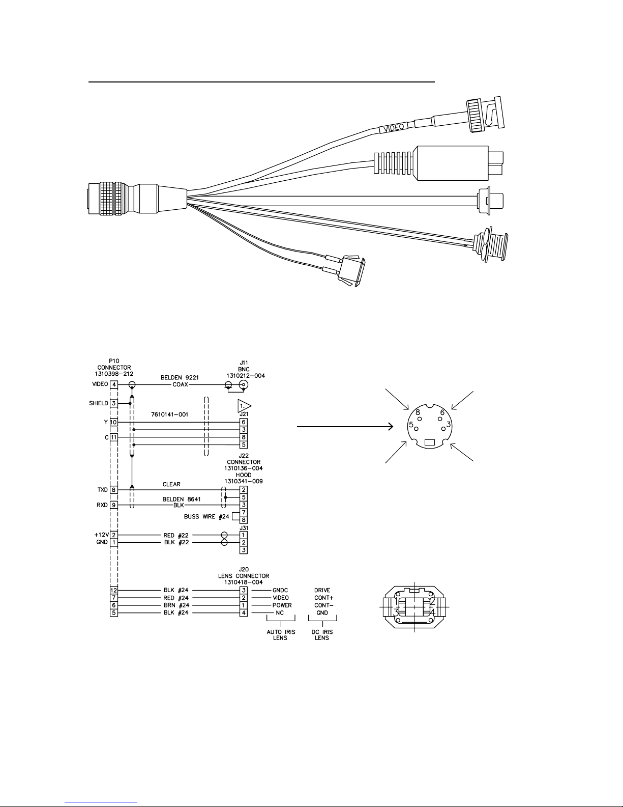
3610 CAMERA
12 V - No Freeze Frame - with Auto, DC, or Manual Iris Lens
6 FOOT CABLE LENGTH
(Lens leads 4 inch)
TECHNICAL REFERENCE
J11
P10
4-inch
length
Y-C
S-Video
J21
J22
J31
J20
NOTE: Pin numbering varies from mfg. to mfg.
with this type plug. Always wire to the following
physical layout diagram when wiring any Y-C plug.
C
Y
16
C
Ground
WIRING VIEW OF PLUG
1
Wiring View
of J20
2
43
Figure 9. Test Cable, CTC-34 (12 V dc)
(No Freeze Frame - Auto/Dc Iris Conguration)
Y
Ground
6X-1042D
Page 17
TECHNICAL REFERENCE
3610 CAMERA
Figure 10. Test Cable, CTC-32 (modied for H & V)
(12 V dc Freeze Frame Conguration)
6X-1042D
17
Page 18
3610 CAMERA
Optional connection
for 12 V dc Camera
with auto or dc iris lens
POWER SUPPLY
5 V dc 500 mA or
12 V dc 350 mA
DEPENDS ON MODEL
OF CAMERA
COMPOSITE
VIDEO
TECHNICAL REFERENCE
OPTIONAL
SCENE
MONITOR
COMPUTER
MONITOR
CAMERA
5V dc or 12 V dc
Note: Camera options determine
what connections are possible.
Power, lens, freeze frame, and
H/V drive are closely related
to possible choices.
freeze
Freeze Frame may also be GUI controlled
Figure 11. Typical Interconnections
3.1.3.1 Off (Fixed Weighted Average)
Select this compensation when the subject of
interest is a backlighted dark image that does not
move. The foreground subject will gain detail as
a result of being made brighter, but the backlight
area behind the subject will have a loss of detail
due to this overall increased brightness level. In
this mode, each of the window areas (ref: para-
graph 3) of the scene have xed values assigned
to them for determining how to render the overall
scene.
3.1.3.2 Automatic Weighted Average
PC
FREEZE FRAME
TRIGGER INTERFACE
SYNC GENERATOR
H Drive
V Drive
RS-232C
Y-C
S-video
3.1.3.3 Brighten Dark Areas
This selection enhances details of a darker
foreground subject that is backlighted. The bright
backlighted area will be made even brighter with a
resulting loss of detail.
3.1.3.4 Darken Bright Areas
Use this selection to enhance detail in the
backlighted area of the scene. The foreground
image is made even darker, but use of a gamma
curve can maintain detail of the foreground part of
the image if this is necessary.
SERIAL
PORT
FRAME
GRABBER
Select this compensation when the subject
of interest is a backlighted image moving against
the bright background. The foreground subject will
gain detail as a result of being made brighter, but
the backlight area behind the subject will have a
loss of detail due to this overall increased brightness level. In this mode, the weighting values are
automatically controlled in response to the light
intensity detection window.
18
3.1.4 Save Button
Clicking the Save button sends the current
GUI selections to the Camera. It will also store
them into any GUI Preset (1 to 10) that may currently be selected — other than in the Factory
Default selection. If Factory is the active preset,
then the current selections are not stored by the
GUI. (Also, clicking the save button is not
6X-1042D
Page 19
TECHNICAL REFERENCE
required to send menu selections to the
Camera. This occurs immediately when a menu
selection is changed.)
3.1.5 EEPROM Button
Clicking the EEPROM button stores the
current GUI settings in the Camera memory. This
then becomes the Camera default settings until
new settings are entered by pressing the EEPROM button again with different selections.
3.2 Lens/Aperture (Lens Dialog) Window
3610 CAMERA
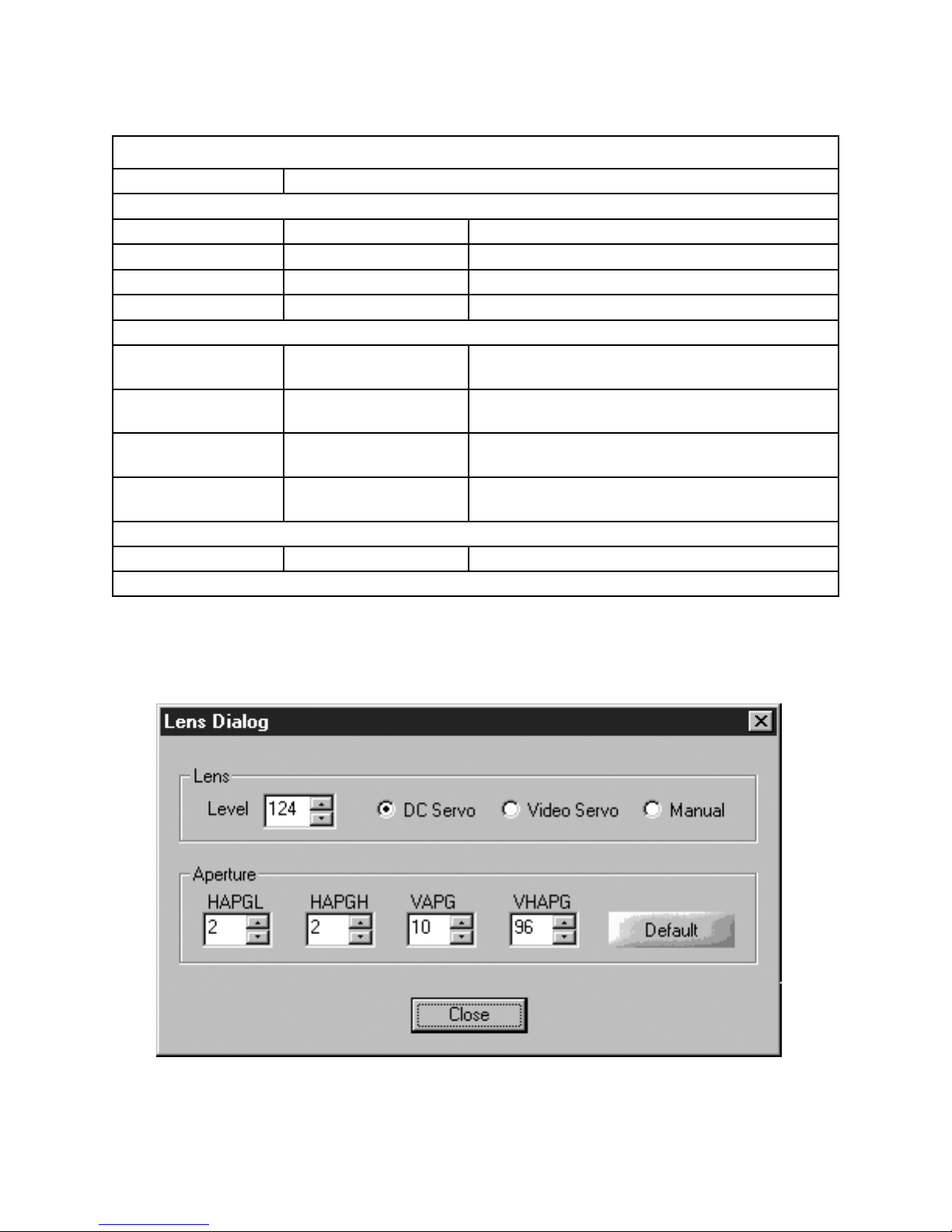
The Lens area of this screen (gure 14) provides settings for a dc iris lens, an auto iris (video
driven) lens, or for a manual lens for which no
settings are required.
3.2.1 Lens Area
Level offers selections from 109 to 149 for
setup of a dc iris lens. Dc Servo should be selected for use with dc iris lens. Select Video Servo
for auto iris lenses.
3.2.2 Aperture Area
The Aperture area of this screen provides
settings for horizontal and vertical aperture. Table
8 lists these four settings together with the available values.
3.3 Set AE Windows (Set Weight)
Window
Automatic gain control for a typical Camera
is typically performed by monitoring the overall
scene video level and then making adjustments to
compensate when it becomes too high or too low.
The 3600 Camera, however, divides the
scene into ve areas that can be re-sized and
shaped as desired. Each area is assigned a relative weight (from 1 to 15) for its contribution to
the automatic gain control function of the Camera.
For example, a high intensity light in one corner of
the scene could be assigned a minimum inuence
upon gain by forming a small window over it and
then assigning that window a low value (perhaps
“1”).
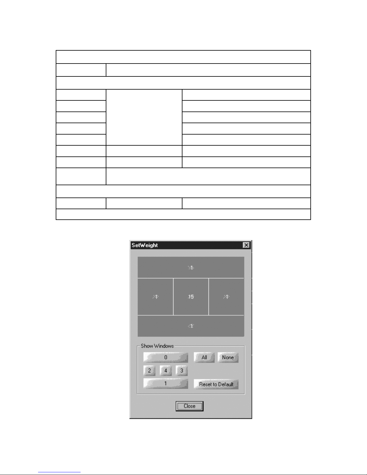
Figure 15 shows the default size and loca-
Figure 12. About Model 3600 Screen
tion for these windows. These lines can be pulled
to other locations by clicking and pulling on them
with a mouse. There is an underlying grid to which
they snap.
The Show Windows area of the screen
makes if possible to overlay the windowing lines
to the video of the scene. The location of these
buttons corresponds to the window areas shown
above. Clicking on a button turns on a transparent overlay for that window area. The All and
None buttons turns on and off an overlay of all the
areas.
Reset to Default re-sizes the window grids to
the factory set default size/locations.
Clicking the close button closes the window.
4.0 STATIC DISCHARGE PROTECTION
Procedures in this manual do not require
entry into the housing of the Camera. However in
the event that an open unit were available, the following precautions should be followed:
CAUTION
This Camera contains sensitive devices
that can be damaged by static discharge.
Use appropriate static control methods
when working inside the Camera.
Components used in modern electronic
equipment, especially solid state devices, are
susceptible to damage from static discharge. The
relative susceptibility to damage for semiconductors varies from low with TTL to high with CMOS.
6X-1042D
19
Page 20
3610 CAMERA
TECHNICAL REFERENCE
NOTE: The Ext Sync (External Sync) selection
should be HDVD (Horizontal Drive Vertical Drive)
when a camera has been optioned for H and V
drive inputs. Special order cameras having the
Comp (Composite) sync input feature should use
the Comp selection
Figure 13. DSP3600 “Home” Screen
20
6X-1042D
Page 21
TECHNICAL REFERENCE
Table 7. DPS3600 “Home” Screen
FUNCTION AREA
NAME EFFECT
Misc
Lens/Aperture Opens new screen for either lens iris setup or aperture conditions
Set AE Windows Opens new screen for setting gain control windows size and locations
About
About Cohu 3600 Opens new window identifying program and version level
BLC (Back Light Compensation)
Off Windowed xed weighting (5 areas) [Fixed Weighted Average]
Auto Weighted Average Windowed automatic weighting
Brightens dark areas Brightens Dark Areas of Image
Darkens bright areas Darkens Bright Areas of Image
Ext Sync
Comp Conditions the camera for the composite as the external sync input (special order cameras only)
HDVD Conditions the camera for horizontal drive & vertical drive as the external sync input
Gamma (gures 17 and 18)
0, 1, 2, 3, 4, 5, 6, 7, 8, or 9 can be selected (0 is least curve amount of curve, 7 is maximum
Preset
curve). Gamma 8 is standard linear response. Gamma 9 is a linear response but with about 15%
increased output — at the expense of additional noise
3610 CAMERA
AWB (Auto White Balance)
Auto Camera automatically adjusts white balance response curve
Manual Up / Down buttons adjust white balance response curve manually
User
Activates red (top) and blue
(bottom) sliders to right
Red slider changes red response curve
Blue slider changes blue response curve
Exposure
Gain Auto / manual selectable
AGC Max Selectable 1 to 255
Shutter Auto / manual selectable
Integration Off / on selectable.
In manual: 0 through 7 selectable; in Auto, maximum AGC Max
selection to right is activated
Llimits the maximum amount of available gain increase when in
Auto mode. 1 is min, 224 is a nominal setting, 255 is max avialable
In manual: 1/50, 1/100, 1/250, 1/500, 1/1,000 1/2,000 1/4,000,
1/10,000, 1/20,000, 1/50,000 sec
2, 3, 4, 5, 10, 20, 40, 80, 160, 320, 510 elds available when On
selected. Manual Integration only available with gains, shutter &
lens in manual mode.
Effects
Horizontal Flip Swaps the left and right of scene (not top and bottom)
Vertical Flip Swaps the top and bottom of scene (not left and right)
180° Rotate Rotates scene so top right becomes bottom left
Freeze Captures the current scene and continues to output it
Y-Invert Inverts the luminance signal
C-Invert Inverts the chroma signal
Color Bars Provides color bars at the output
Monochrome Removes chroma from the output
Continued on next page
6X-1042D
21
Page 22
3610 CAMERA
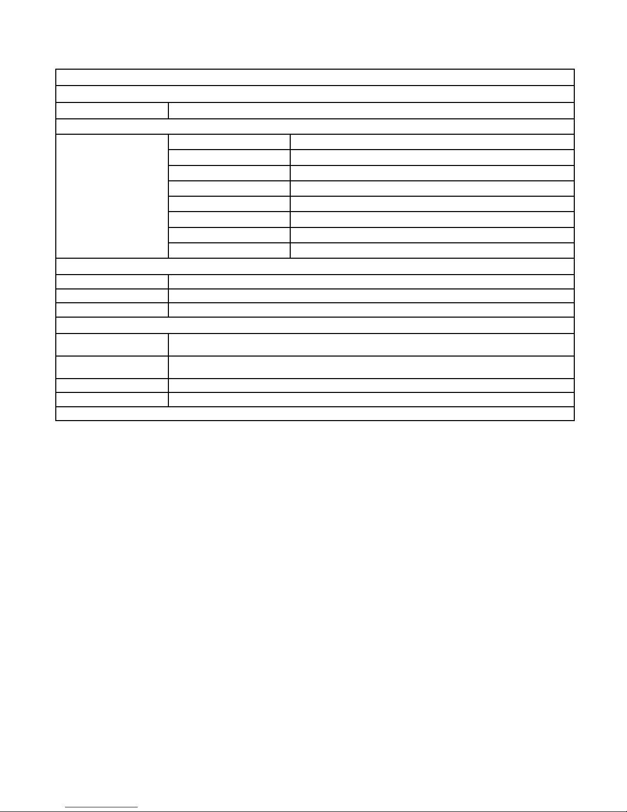
Table 7 (continued)
FUNCTION AREA
NAME EFFECT
Effects (continued)
1x Removes any digital zoom in effect
In Digitally zooms in
Out Digitally zooms out
Zoom Control
Preset drop down menu Choose from factory default or presets 1 through 7
Save Saves preset 1 through 7 settings
EEPROM Saves current entries to the eeprom - becomes Camera power up default
Transmit Indicator and
transmit data line
Receive Indicator and
data receive line
COM Select from COM1 through COM3
Close Closes the DSP3600 screen
Indicator lights when data is being transmitted and hex code of data sent is shown
Indicator lights when data is being received and hex code of data sent is shown
Tilt up button Moves up in the scene
Tilt down button Moves down in the scene
Pan right button Moves right in the scene
Pan left button Moves left in the scene
Center button Returns to the center of the scene
Presets
Message and COM Area
end
TECHNICAL REFERENCE
Most other semiconductors fall between TTL and
CMOS in susceptibility to static discharge. As a
minimum, therefore, observe the following practices when working inside this or any other electronic equipment:
1. Use conductive sheet stock on the work bench
surface.
2. Connect the sheet stock to ground through an
1 megohm or greater value resistor.
3. Use a wrist strap connected to ground through
an 1 megohm or greater value resistor when
working at the bench.
4. Maintain relative humidity of the room above
30 percent. This may require a room humidi-
er. Working on circuits with relative humidity
below 30 percent requires extraordinary procedures not listed here.
5. Use antistatic bags to store and transport an
exposes chassis, circuit boards, and components. Use new antistatic bags. Old, used bags
lose their static protection properties.
This list serves as a reminder of the minimum acceptable practices. Be sure that all static
discharge devices at the work bench are properly
installed and maintained. Standard grounding
mats and wrist straps purchased for use at work
benches are supplied with leads having current
limiting resistors for safety. Never substitute with a
grounding lead not having the resistor.
5.0 UNPACKING AND RECEIVING
INSPECTION
This item was thoroughly tested and carefully packed in the factory. Upon acceptance by
the carrier, they assume responsibility for its safe
arrival. Should you receive this item in a damaged condition, apparent or concealed, a claim for
22
6X-1042D
Page 23
TECHNICAL REFERENCE
NAME EFFECT
Level Setting range Adjustment range from 109 to 149 (DC IRIS only)
DC Servo For dc iris lens Sets the dc iris drive stage for the lens being used
Video Servo For auto / video iris lens Sets the auto iris video drive stage for lens used
Manual For manual iris lens Level setting grayed out when in manual
HAPGL
HAPGH
VAPG Vertical Aperture Gain
VHAPG
Close Click button Closes the Lens Dialog window
Horizontal Aperture Gain
Low
Horizontal Aperture Gain
High
Vertical / Horizontal
Aperture Gain
3610 CAMERA
Table 8. Lens Dialog Screen
FUNCTION AREA
Lens
Aperture Correction
0, 1, 2, & 3 available for selection
0, 1, 2, & 3 available for selection
0, 1, 2, 3, 4, 5, 6, 7, 8, 9, 10, 11, 12, 13, 14, 15
available for selection
0, 16, 32, 48, 64, 80, 96, 112, 128, 144, 160, 176,
192, 208, 224, 240, & 255 available
Close
end
6X-1042D
Figure 14. Lens Dialog Screen
23
Page 24
3610 CAMERA
NAME EFFECT
TECHNICAL REFERENCE
Table 9. Set Weight Screen
FUNCTION AREA
Show Windows
0
2 Click 2 to place this window into scene video
4 Click 4 to place this window into scene video
3 Click 3 to place this window into scene video
1 Click 1 to place this window into scene video
All Show all windows in video Click to place all windows into scene video
None Show no window in video Click to remove all windows from scene video
Reset to Default
Close Click button Click to close the window
Physical locations of click
buttons corresponds to
corresponding window
areas shown above
Resets size and location of windows to the factory default
Click 0 to place this window into scene video
Close
end
24
Figure 15. Set Weight Screen
6X-1042D
Page 25

TECHNICAL REFERENCE
damage must be made to the carrier.
To return the product to the factory for service, please contact the Customer Service Department for a Return Authorization Number. If a visual inspection shows damage upon receipt of this
shipment, it must be noted on the freight bill or express receipt and the notation signed by the carrier’s agent. Failure to do this can result in the carrier refusing to honor the claim.
When the damage is not apparent until the unit is unpacked, a claim for concealed damage
must be made. Make a mail or phone request to the carrier for inspection immediately upon discovery of the concealed damage. Keep all cartons and packing materials.
Since shipping damage is the carrier’s responsibility, the carrier will furnish you with an inspec-
tion report and the necessary forms for ling the concealed-damage claim
6.0 PREPARATION FOR SHIPMENT AND STORAGE
For storage periods exceeding about one month, seal the unit in a vapor-proof bag containing a
fresh desiccant pack.
Maintain the Camera storage environment within a range of -30 to 85 °C (-22 to 185 °F).
For shipment, package with enough foam padding or other packing material to prevent damage that can occur during shipping. The original shipping carton is a good container if it has not been
damaged or subjected to excessive moisture. Please contact the Customer Service Department for
a Return Authorization (RA) number before sending any shipments to the factory.
Prominently display the RA number on the outside of the shipping container(s) and on paperwork contained inside. Give a brief description of why the equipment is being returned and list the
symptoms of any problems being experienced with the equipment.
3610 CAMERA
6X-1042D
25
Page 26
3610 CAMERA
TECHNICAL REFERENCE
Figure 17. Non-linear Y-gamma Characteristics
Figure 18. Linear Y-gamma Characteristics
26
6X-1042D
Page 27
TECHNICAL REFERENCE
7.0 WARRANTY
Please refer to the Cohu website for product warranty information:
http://www.cohu-cameras.com/warranty/WarrantyStatement.pdf.
3610 CAMERA
6X-1042D
Revision History
Revision Date Comments
This manual has been revised to comply with
C 4/28/11
D 6/22/12
the latest engineering requirements. See
ECO 030972 for the list of changes
The manual is revised to replace contact
information with a link to the web page.
27
 Loading...