

COHU 3220 Series Installation Manual
3220 SERIES ANALOG
ENVIRONMENTAL CAMERA
INSTALLATION MANUAL
RS-232
RS-422
Technical Manual 6X-1082a
Figure 1. Model 3220 NTSC or PAL Camera
March 25, 2008

3220 CAMERA
INST
CAUTION
Do not power the 24 V ac version of
this camera directly from a Variac. It
will blow up the power supply.
ALLA
TION MANUAL
2
Figure 2. Camera Version with Pigtail Cable
(Model 3221 or Model 3223)
Also available without factory wired pigtail cable to allow for direct
connections to internal terminals
(Model 3222 or Model 3224)
Two other manuals related to this camera are available:
1. Manual 6X-1084. The setup GUI - for conguring camera
characteristics
2. Manual 6X-1085. The protocol - for use by programmers to
write software for controlling camera functions
6X-1082a

INSTALLATION MANUAL
1.0 GENERAL DESCRIPTION
This introduction briey describes the overall
characteristics of the Model 3220 Camera (gure
1) related to its installation. Complete specications
can be found on the CD supplied with this camera.
Electrical Characteristics
1.1
The 3220 provides a highly sensitive CCD
camera in an environmental housing.
The 3220 is available with either NTSC or PAL
video output, depending on the model. Operating
power is either 12 V dc or 24 V dc/ac — again de-
pending on the model.
It has an integrated camera module with 3.3
mm to 99 mm zoom lens.
Data communications with the camera can be
either RS-232 or RS-422 for control of DSP func-
tions.
It has a day/night feature that increases sensi-
tivity by reverting from color to monochrome output
in low light conditions. This feature can be made to
operate automatically or by manual control when
desired.
A model number interpretation diagram ap-
pears in gure 4. That diagram shows the various
basic congurations of the 3220.
1.1.1 Initial Setup Software
3220 CAMERA
Figure 3. Camera Front View
An integral sun shield over the camera module
housing minimizes heat build up that could result
from direct sun light on the camera module housing.
The mounting base (gure 5) for the 3220 has
a two-hole pattern on a sliding “T” slot type bar for
attachment to a suitable base.
A 3220 can be mounted on any one of ve me-
chanical congurations. The model number denes
the mounting equipment supplied as part of the
3220. Table 1 lists the mounting items supplied for
each of the mounting congurations available with a
3220.
Graphical User Interface (GUI) software is
available for setting the address and performing
eld tests and setups for each camera. This is
included on a CD provided with the camera. The
reference manual for this GUI is technical manual
6X-1084 which is also included on the CD.
1.1.2 Camera Firmware Protocol
The protocol for a programmer to develop
software for controlling the camera is available on
the CD provided with the camera. Refer to technical
manual 6X-1085.
Mechanical Characteristics
1.2
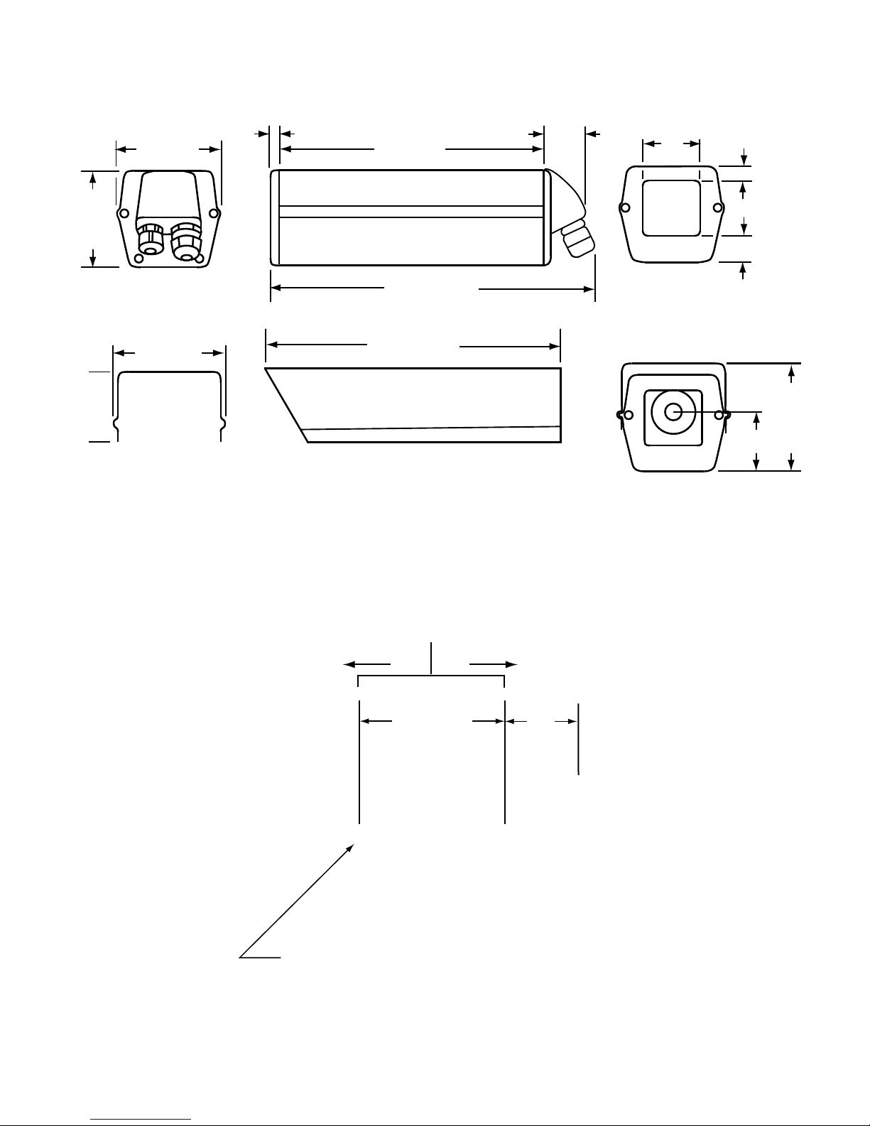
Dimensions are shown in gure 5. The 3220
consists of an IP66 environmentally sealed camera
module. This housing is not pressurized with an
inert gas such as dry nitrogen.
6X-1082a
2.0
INSTALLATION
This section covers the general requirements
of installing the 3220 including cabling and power
requirements. In addition to the actual installa-
tion requirements, this section covers a number of
other items including static discharge protection and
proper shipping and handling of the 3220.
Unpacking and Receiving Inspection
2.1
This item was thoroughly tested and carefully
packed in the factory. Upon acceptance by the car-
rier, they assume responsibility for its safe arrival.
Should you receive this item in a damaged condi-
tion, apparent or concealed, a claim for damage
must be made to the carrier.
If a visual inspection shows damage upon
receipt of this shipment, it must be noted on the
3
3220 CAMERA
SERIES
POWER
Camera in IP66 Rated
Unpressurized
Housing
1 12 V dc with interface cable
2 12 V dc
3 24 V ac/dc with interface cable
4 24 V ac/dc
MOUNT
3 NTSC
7 PAL
Not
Assigned
WALL (Wall Mount)
PEDD (Pedestal Mount)
CEIL Ceiling Mount)
POLE (Pole Mount)
HDWM (Heavy Duty Wall Mount)
VIDEO
FORMAT
**
**
*
*
*
***
***
322 x—x000 xxxx
WALL (Wall Mount) is included
with all models
Wired to environmental connector on a pigtail
An HDWM (Heavy Duty Wall Mount) is included
with the POLE mount configuration
INST
ALLA
TION MANUAL
Figure 4. Model Number Interpretation Diagram
freight bill or express receipt and the notation signed
by the carrier’s agent. Failure to do this can result in
the carrier refusing to honor the claim.
When the damage is not apparent until the unit
is unpacked, a claim for concealed damage must be
made. Make a mail or phone request to the carrier
for inspection immediately upon discovery of the
concealed damage. Keep all cartons and packing
materials.
Since shipping damage is the carrier’s respon-
sibility, the carrier will furnish you with an inspection
report and the necessary forms for ling the con-
cealed-damage claim.
please contact the Customer Service Department
for a Return Authorization (RA) Number.
2.2
handled, the following precautions should be fol-
lowed:
To return the product to the factory for service,
Static Discharge Protection
In the event that a disassembled 3220 is being
4
ment, especially solid state devices, are susceptible
to damage from static discharge. The relative sus-
ceptibility to damage for semiconductors varies from
low with TTL to high with CMOS. Most other semiconductors fall between TTL and CMOS in suscep-
tibility to static discharge. As a minimum, therefore,
observe the following practices when working inside
this or any other electronic equipment:
CAUTION
This 3220 contains sensitive devices that can be
damaged by static discharge. Use appropriate static
control methods when working inside the 3220.
Components used in modern electronic equip-
1. Use conductive sheet stock on the work bench
surface.
2. Connect the sheet stock to ground through a 1
megohm or greater value resistor.
3. Use a wrist strap connected to ground through a
1 megohm or greater value resistor when working at
the bench.
6X-1082a
INSTALLATION MANUAL
MOUNT
DESIGNATION
MOUNT
DESCRIPTION
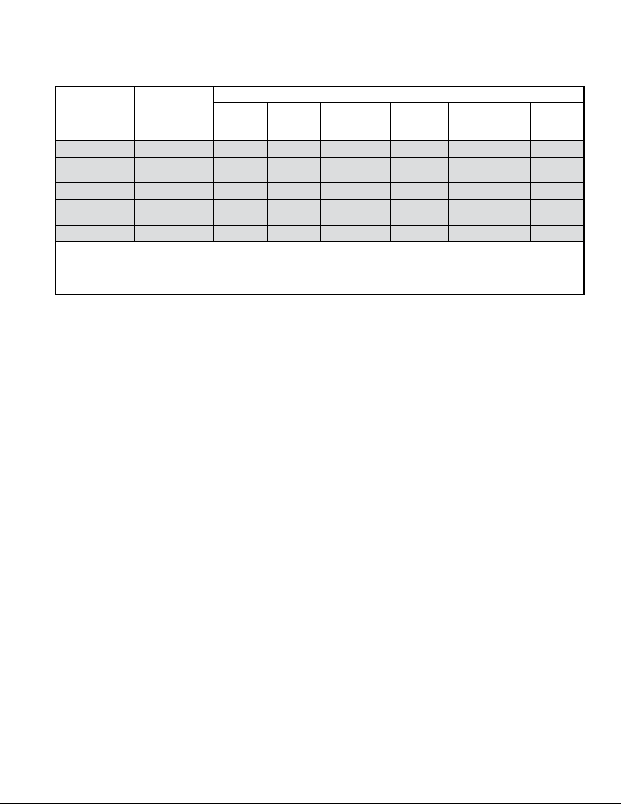
Table 1. Mounting Congurations
ITEMS SUPPLIED
3220
CAMERA
WALL
MOUNT
PEDESTAL
MOUNT
CEILING
MOUNT
3220 CAMERA
HEAVY DUTY
WALL MOUNT
POLE
MOUNT
WALL
PEDD
CEIL
HDWM
POLE
Note: Read the table horizontally. A dot “•” designates an item supplied for each mounting conguration. As an example,
for the CEIL (Ceiling Mount) three items are supplied: a 3220 camera , a wall mount, and a ceiling mount.. Notice in
the Wall Mount column that it is always supplied with a camera. It is required only for a WALL mount installation, but
can be used if desired as an alternate mounting method if the need arises.
4. Maintain relative humidity of the room above 30
percent. This may require a room humidier. Working
on circuits with relative humidity below 30 percent
requires extraordinary procedures not listed here.
5. Use antistatic bags to store and transport an ex-
posed chassis, circuit boards, and components. Use
new antistatic bags. Old, used bags lose their static
protection properties.
Wall Mount
Pedestal
Mount
Ceiling Mount
Heavy Duty
Wall Mount
Pole Mount
• •
• • •
• • •
• • •
• • • •
mating connector is supplied for the system inter-
connection cable. These are 18-pin MS type metal
connectors. Figure 29 shows this connector kit.
Two hex (Allen) wrenches are also supplied
with the camera. One is for removing housing
screws to gain access to the interior of the camera
and the other hex wrench is for the ball head adjust-
ment on the basic WALL mount.
This list serves as a reminder of the mini-
mum acceptable practices. Be sure that all static
discharge devices at the work bench are properly
installed and maintained. Standard grounding mats
and wrist straps purchased for use at work benches
are supplied with leads having current limiting resis-
tors for safety. Never substitute with a grounding
lead not having the resistor.
Equipment Supplied
2.3
The basic conguration consists of the camera
and a wall mount arm. The housing is tted with an
integral sun shield assembly that covers the camera
module housing. This sun shield minimizes heat
buildup inside the camera by shielding it from the
direct rays of the sun.
If either a model 3221 or model 3223 has been
supplied (9-inch pigtail cable attached to camera) a
2.3.1
Mounting Hardware Supplied
Several assortment of nuts, bolts, at washers,
and locking washers may be provided depending on
which mounting conguration has been selected.
1. The standard wall (WALL) mount supplied with all
cameras is shipped with a 1/4-20 x 1/2 inch bolt and
a locking washer.
2. Pedestal, ceiling, heavy duty wall mounts, and
pole mounts are shipped with hardware kit 84988 — which supplies various bolts and washers to
choose from when attaching a camera to the mount
being used.
The pole mount is also shipped with an ad-
ditional hardware kit for attaching the clamp to the
pole and for attaching the heavy duty wall mount to
the clamp. See gure 26.
6X-1082a
5

3220 CAMERA
Table 2. Mounting Hardware Kit 8498-8
ITEM DESCRIPTION QTY PART NUMBER WHERE USED
1 1/4-20 x 1/2 Hex Head Screw 2 2010730-006 Pedestal Mount
2 1/4-20 x 5/8 Hex Head Screw 2 2010730-005 Ceiling Mount
3 1/4 Spring Lock Washer 2 2010732-002 Pedestal Mount; Ceiling Mount
4 1/4 Flat Washer 2 2010731-002 Pedestal Mount; Ceiling Mount
5 1/4-20 x 1/2 Flat Head Screw 2 0310010-091 Heavy Duty Wall Mount
Notes: All dimensions in inches. This kit provides the hardware necessary to attach a 3220 series camera to a
Heavy Duty Wall Mount, a Ceiling Mount, or a Pedestal Mount. This hardware must be used in place of the metric
hardware included with these mounts. (The two athead screws in item 5 are required for the Pole mount option,
too, since it uses the Heavy Duty Wall Mount as part of its assembly.)
2.5
2.3.1 Mounting Hardware Not Supplied
No hardware is supplied for securing a wall,
ceiling, or pedestal mount to their mounting surface.
However, the pole mount does not require any
additional hardware to mount it to a pole. It can be
clamped to a pole with two threaded rods that are
supplied in its hardware kit.
Two versions of the camera have slightly dif-
ferent cabling requirements. With one version the
system interconnection cable plugs into a camera
connector. With the second version the system interconnection cable must be directly wired to inter-
nal terminals inside the camera.
INST
Cabling Requirements
ALLA
TION MANUAL
Equipment Required but Not Supplied
2.4
As a minimum the 3220 requires a source of
operating power, a monitor on which to view the
scene, an interconnection cable, and a computer
running Graphical User Interface (GUI) software for
control of the 3220 if this is desired.
During maintenance and setup operations us-
ing either a laptop or desktop PC it is likely that a
USB to RS-232 converter will be required.
Typically PC’s have had only an RS-232 port
— and rarely an RS-422 port.
However, newer PC’s and laptops no longer
have an RS-232 port and instead rely on USB and
other newer type ports.
With these computers, a USB to RS-232 con-
verter will be required. Be aware that some of these
converters do not provide reliable RS-232 com-
munications If problems are experienced determine
whether it is the converter.
If it is desired to use the RS-422 feature of the
camera it will then be necessary to add an RS-232
to RS-422 converter.
Or a USB to RS-422 converter could be used
directly but these are not common devices.
2.5.1 Model 3221 and 3223 Cameras
For the model 3221 and model 3223 versions
of the camera, system interconnections are made
to the connector on a permanently attached 9-inch
“pigtail” cable. A connector (gure 29) is provided to
mate with this pigtail connector.
Figure 6 through gure 15 show typical cables
available for use with the pigtail connector.
2.5.2 Model 3222 and 3224 Cameras
For the model 3222 and model 3224 versions
of the camera, system interconnections are made
directly to terminals inside the camera (gure 16
and gure 17).
2.5.3 Customer Supplied Cable
A high quality multiconductor shielded cable
must be used with this camera both to minimize EMI
radiation and to reduce susceptibility to interference.
The cable must have an overall shield with at
least 95 percent coverage.
Data wiring must be twisted pairs similar to that
used in CAT-5e cable. A data ground wire must be
used.
6
6X-1082a
INSTALLATION MANUAL
3.66 (93)
2.44 (62)
3.66 (93)
3.27 (83)
3.46 (88)
8.15 (255)
6.3 (160)
1.42
(36)
0.43
(11)
10.0 (254)
1.87
(47.5)
0.87 (22)
1.87 (47.5)
0.53 (13.5)
1.90
(48)
Dimensions in inches and (mm)
Sunshield
(installed on camera)
Sunshield
Sunshield
L
C
See photo below for bottom mounting dimensions
2.75 (69.8)
1/4-20
(Typical two places)
Note: 1/4-20 bolts must not protrude more that
5/16 inch past bottom of camera
1.50
(38.1)
0.63 (16)
0.63 (16)
Note: Mounting bracket slides 0.63 inches
right or left from centered position shown
3220 CAMERA
Figure 5. Dimensions, Model 3220 Series Cameras
6X-1082a
7
3220 CAMERA
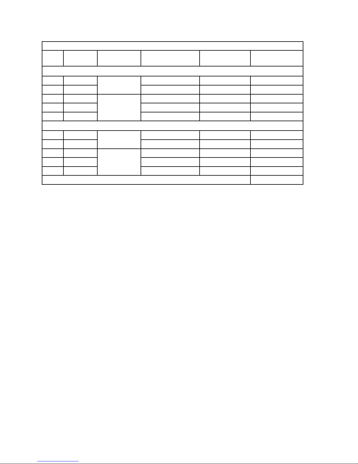
ITEM CABLE
1
2 CA-253B BNC stripped leads D9 female
3 CA-254A
4 CA-254B BNC stripped leads 232/422 converter
5 CA-254M BNC stripped leads RJ-45
6 CA-292A
7 CA-292B BNC stripped leads D9 female
8 CA-293A
9 CA-293B BNC stripped leads 232/422 converter
10 CA-293M BNC stripped leads RJ-45
CA-253A
INST
Table 3. System Interconnection Cable Characteristics
TYPE
DATA
TYPE
VIDEO
CONNECTION
POWER
CONNECTION
12 V dc
RS-232
RS-422
stripped leads stripped leads stripped leads
stripped leads stripped leads stripped leads
24 V ac / 24 V dc
RS-232
RS-422
stripped leads stripped leads stripped leads
stripped leads stripped leads stripped leads
ALLA
TION MANUAL
DATA
CONNECTION
Coaxial cable must be 75 ohm RG-59/U and
not have any type of iron conductors. Belden 8241F
is a typical good coax.
Power wiring must be of sufcient size to main-
tain proper operating voltage at the camera. Power
wires can be paralleled to reduce voltage drop.
2.5.2 Pigtail Connector Pinout
Table 5 lists pin functions on the pigtail connec-
tor for various versions of the model 3221 and 3223
cameras.
2.5.3 System Interconnection Cables
Eight system interconnection cables are available for use with the model 3221 and 3223 cam-
eras.
Table 3 lists these cables and describes their
characteristics.
The major breakdown between cables types is
whether they are for 12 or 24 volt cameras.
Each of these two groups is then further sub-
divided into whether a camera is to use RS-232 or
RS-422 communications.
The nal determination is whether the cable
should have stripped leads for all the eld instal-
lation connections or whether certain connectors
and/or data converters should be provided with the
cable.
2.6
Power Requirements
Two versions of the 3220 are available in rela-
tion to power input requirements:
1. The model 3221 and model 3222 operate from 12
V dc +/- 10 percent;
2. The model 3223 and model 3224 operate from
either 24 V ac or 24 V dc +/- 10%.
Power consumption is less than 4 watts when
the internal heater is off and less than 20 watts
when the thermostat turns the heater on.
CAUTION
Do not power the 24 V ac version of
this camera directly from a Variac. It
will blow up the power supply.
8
6X-1082a
 Loading...