

COHU 2740 SERIES Installation And Operation Manual
2740 SERIES
ENVIRONMENTAL CAMERA
INSTALLATION AND OPERATION MANUAL
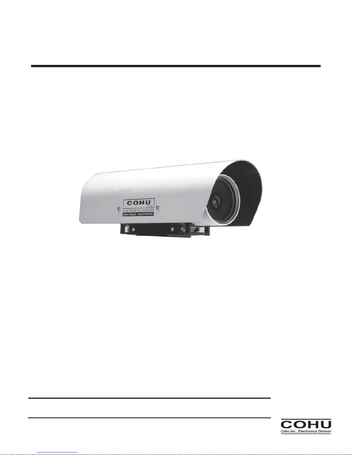
Figure 1. Low Light Level Environmental Camera
Technical Manual 6X-1048B
Phone: 858-277-6700
Fax: 858-277-0221
Shown with optional sun shield
info@cohu.com
www.cohu-cameras.com
May 10, 2011
Cohu Electronics • 12367 Crosthwaite Circle • Poway CA • 92064

2740 CAMERA
TABLE TITLE PAGE
1 Specifications 4
2 Items Supplied 6
3 Rear Panel Connector and Mating Cable Plug 7
4 Pin F unctions , Re ar Pane l C onnec tor 11
FIGURE TITLE PAGE
1 Low Light Level Environmental Camera 1
2 Sensor Wavelength Response Characteristics 3
3 Model Number Interpretation Diagrams 5
4 Dimensions, Model 2740Camera 8
5 Typi cal Interco nne cti o n C able 9
6 Rear P anel Features (B asic Came ra) 10
7 Conne ctor Pin Orienta ti on 10
8 Rear Pane l F eatures (O ptio ned Cam era) 11
9 Humidity Indicators 12
SECTION TITLE PAGE
1.0 GENERAL DESCRIPTION 3
1.1 Electrical Characteristics 3
1.1.1 Sensor Characteristics 5
1.2 Mechanical Characteristics 5
2.0 INSTALLATION 6
2.1 Unpacking and Receiving Inspection 6
2.2 Stati c D ischarge P rotection 6
2.3 Equipment Supplied 7
2.4 Equipment Required but Not Supplied 7
2.5 Cabling Requirements 7
2.6 Power Requirements 7
2.7 Mounting Requirements 7
2.8 Line Lock Operation 8
2.9 Installation Procedure 8
2.9.1 IDGenerator Messages (Option) 8
2.9.2 Rear Panel Features 10
2.10 Front Window Features 13
2.11 Preparation for Shipment and Storage 13
3.0 OPERATION 13
LIST OF
SECTIONS
INSTALLATION AND OPERATION
LIST OF
FIGURES
LIST OF
TABLES
2
6X-1048B
INSTALLATION AND OPERATION
500
400
600
700 1000
900
800
0
0.1
0.2
0.3
0.4
0.5
0.6
0.7
0.8
0.9
1.0
Wavelength (nm)
Relative Response
Standard Sensitivity
Enhanced Near IR
Sensitivity
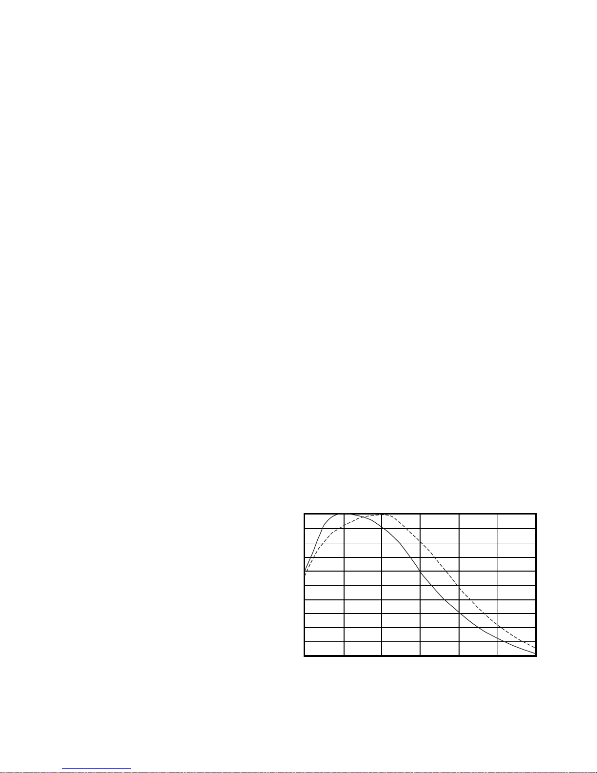
Note: Both curves are normalized to 1.0 and thus the graph does not show comparative output levels
2740 CAMERA
1.0 GENERAL DESCRIPTION
This introduction briefly describes overall
characteristics of the Model 2740 monochrome
Camera (figure 1) related to its installation and
operation.
1.1 Electrical Characteristics
The 2740 camera provides a highly sensitive
interline transfer CCD Camera in a pressurized
environmental housing. All electrical connections
are via a single 39 pin rear panel connector. Table
1 lists electrical, mechanical, and environmental
specifications for the 2740 Camera.
Video output may be provided by an optional
fiber optic connector added on the rear panel.
When this option is selected, the 75 ohm output
on the 39 pin connector should not be terminated.
Any temporary connections to this 75 ohm output
for maintenance purposes should be done with a
short 75 ohm coax cable to avoid any “stub” effect
that may cause ghosting in the video.
The Camera operates with either NTSC or
PAL format, depending on the model. Both of
these formats are available in a high-sensitivity
version.
This Camera operates at an internal clock rate
of 28.6363 MHz (NTSC) or 28.375 MHz (PAL).
If the phase adjust line lock option is installed,
the vertical interval of the camera is referenced to
the 60 Hz power input for NTSC (or the 50 Hz
power input for PAL). A six position switch on
the rear panel then makes it possible to shift
this reference in 60 degree increments so that
the camera can be phased with other cameras in the system that may not have the
same power line phase reference. This phase
difference can occur either because the other
cameras are on a different phase of the power
source or perhaps because they are connected to a power source operating from a
different transformer.
The Camera is available with either 115 V
ac or 24 V ac input power — depending on the
model. An internal 20 watt heater cycles on an
6X-1048B
off at low environmental temperatures to maintain
temperature inside the housing at operating
levels.
When an optional zoom lens is installed,
dedicated pins on the connector provide for
control of zoom, focus, and iris. Pins are also
assigned for location of the lens zoom position.
When an optional ID generator is mounted
inside the camera housing, it can be programmed
to provide messages in the video. It also provides
barrel pressure and temperature when these
displays are turned on.
Programming and control of the ID generator
is via RS-422 on the rear panel multipin connector. Cohu’s Win MPC graphical user interface
(GUI) software can be used to program these
messages. (WinMPC is available at no cost from
the cohu-cameras web site or by mail on CD.) —
or the system control software can be used if it
has been implemented with the proper protocol
messages.
If either shuttering or a manual gain setting is
desired, these setting must be performed before
the camera housing is sealed and pressurized.
Changing either of these optional settings requires
complete disassembly of the camera housing. It
must then be re-sealed, purged with dry nitrogen,
and pressurized with the dry nitrogen before
returning to service. For more information about
the internal camera module refer to Cohu Techni-
Figure 2. Sensor Wavelength
Response Characteristics
3

2740 CAMERA
ELECTRICAL
Format
RS-170: 1/2-inch interline transfer monochrome CCD operating in field mode or
CCIR: 1/2-inch interline transfer monochrome CCD operating in field mode
( both available with extended near IR sensitivity)
Pixels 768 × 494 RS-170; 752 × 582 CCIR
Pixel Cell Size 8.4 (H) × 9.8 (V) µm RS-170 8.6 (H) × 8.3 (V) µm CCIR
Resolution 580 HTVL (RS-170) 560 HTVL (CCIR)
Internal Clock 28.6363 MHz (RS-170) 28.375 MHz (CCIR)
Sync Internal crystal, or rear panel switch adjustable line lock, depending on model
Frame Rate 30 fps (RS-170); 25 fps (CCIR)
Sensitivity, Faceplate
Full video, max gain, agc off: Standard: 0.0012 lux E xtended: 0.0009 lux
80% video, max gain, agc off Standard: 0.0010 lux E xtended: 0.0007 lux
Agc On, extended sensitivity sensor: 0.28 lux, nominal min gain; 80% video, max gain, 0.0007 lux
Gamma 0.6 normal fixed (optional fixed 0.45 or 1.0)
Sharpness Circuit None used
Gain 0 to 46 dB gai n control — either agc or internal manual adjustment
Shutter 1/60 (1/50 CCIR) to 1/100,000 sec; 8 steps (Internal switch access)
S/N 58 dB max; 10 dB S/N with 46 dB gain (0.6 gamma)
Spectral Response See figure 2
Power Input
24 V ac ±10 % or, depending on model,
115 V ac ±10 %
Power Consumption 30 W ; heater draws an additonal 20 W each time it cycles on in cold weather
Video Output
RS-170 or CCIR, depending on model
Fiber optic ST connector output optional
Lens Control Auto iris (video style) and dc iris; zoom lens optional
MECHANICAL
Dimensions 21 inch long × 5.2 inch high (533 x 132 mm), without sun shield. See figure 4
Weight 10 lb (3.9 kg), less lens
Camera Mount 5 each 1/4-20 threaded holes on mounting base attached to barrel housing
Co nnectors
39-pin Bendix PT07C-20-39P, Schrader valve for pressure charging with dry nitrogen, pressure
relief valve, optional fiber optic connector
ENVIRONMENTAL
Temperature
-20 to 60 °C (-4 to 140 °F) operating
-40 to 60 °C (-40 to 140 °F) operating with heaters
-30 to 85 °C (-22 to 185 °F) non operating
Humidity Up to 100 % realtive humidity
Vibration (less lens)
Sine vibration from 5 to 60 Hz, with 0.082 inch total excursion (15 g's at 60 Hz)
Random vibration from 60 to 1,000 Hz, 5 g's rms (0.027 g2/Hz without damage
Shock (less lens) Up to 15 g's, 11 ms, in any axis under non-operating conditions, MIL-E-5400T, paragraph 3.2.24.6
Altitude Sea level to equivalent of 3,000 meters (10,000 feet) 508 mm / 20 inches of mercury)
Air Contaminants
Withstands exposure to sand, dust, fungus, and salt atmosphere, per MIL-E-5400T, paragraph
3.2.24.7, 3.2.24.8, and 3.2.24.9.
Explosion MIL-E-5400T, paragraph 3.2.24.10
Acoustical Noise Greater than 150 dB continuously for 30 minutes
Immunity EN61000-4-3, -4-6, -4-8 interference immunity tests
INSTALLATION AND OPERATION
Table 1. Specifications
4
6X-1048B

INSTALLATION AND OPERATION
SERIES
POWER
VIDEO FORMAT / SENSOR
4.5-inch
environmental
camera
4 24 V ac input
Power
5 115 V ac input
Power
ACCESSORIES
LENS
2 RS-170 1/2-inch standard sensitivity
3 RS-170 1/2-inch extended near ir sensitivity
5 CCIR 1/2-inch standard sensitivity
6 CCIR 1/2-inch extended near ir sensitivity
SYNC
1 Internal crystal
2 Line lock
0 None
4 ID generator
5 Fiber optic video
6 ID generator and
fiber optic video
IRIS
0 Auto/dc iris
3 Electronic iris
274 x — x x x x xxxx
Figure 3. Model Number Inter pretation Diagram
2740 CAMERA
cal Manual 6X-1040 (2700 camera) — available on
the cohu-cameras web site.
A model number interpretation diagram appears in figure 3. That diagram shows the various
basic configurations of the Camera. An optional
sun shield is also available but it is not modeled
into this number sequence.
The following options are available for the
camera:
1. Fiber optic video output
2. ID generator
3. Variable phase line lock
4. Either manual iris lens, auto iris lens, dc iris
lens, or zoom lens
5. Sunshield
1.1.1 Sensor Characteristics
Figure 2 shows the typical response characteristic across relevant wavelengths of the sensor .
This chart shows both the standard sensitivity
curve and the enhanced sensitivity curve.
The camera lens and the window in the barrel
housing will have a slight impact on these curves.
These characteristic curves apply to both
NTSC and PAL sensors.
6X-1048B
1.2 Mechanical Characteristics
Dimensions are shown in figure 4. The Camera consists of a sealed and pressurized 21 inch
long barrel housing attached to a mounting base
with two stainless steel straps.
An optional sun shield can be mounted over
the housing to prevent heat build up from direct
sun light on the barrel. This sun shield extends
beyond the ends of the barrel about three inches
at each end. It can provide some protection from
direct sun exposure on the camera lens in certain
situations.
All electrical connections are made via a 39pin connector located on the rear panel. A fiber
optic option makes video available from a fiber
optic connector located on the rear panel. Video
from the 39 pin connector, then, should not be
used.
A Schrader valve (car tire type valve) on the
rear panel provides for pressurizing the housing
with dry nitrogen. This valve can be used to
occasionally add dry nitrogen as necessary to
maintain pressure in the barrel at about 5 psi (35
kPa).
A pressure relief valve on the rear panel
releases pressure at 20 psi (138 kPa) to prevent
extreme over-pressurization of the housing.
5
 Loading...