

Coherent Solutions SwitchPXIe-1106, SwitchPXIe-1003, SwitchPXIe Series, SwitchPXIe-1103, SwitchPXIe-1009 User Manual
...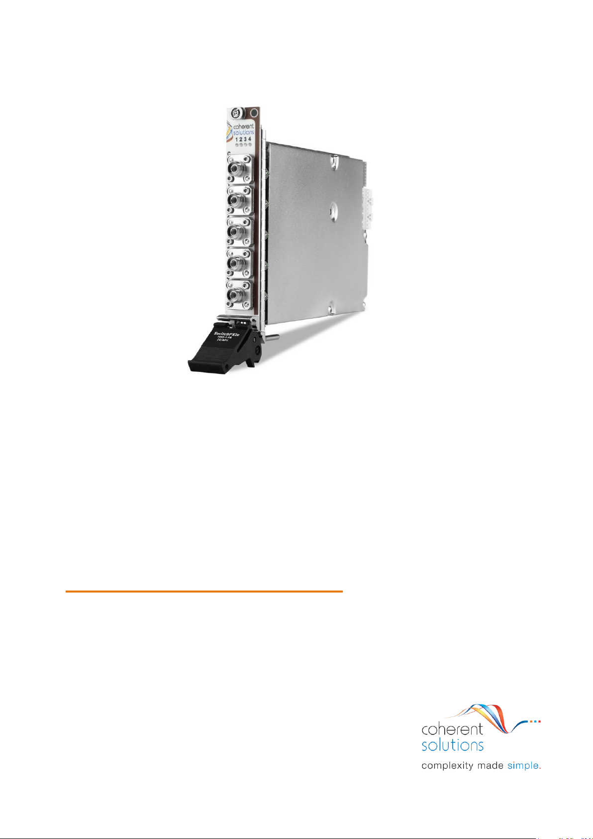
SwitchPXIe
Optical Switch
USER MANUAL

PXIe Platform Optical Switch Module|SwitchPXIe
i
Copyright © 2018 Coherent Solutions Ltd. All rights reserved. No part of this publication may
be reproduced, stored in a retrieval system or transmitted in any form, be it electronically,
mechanically, or by any other means such as photocopying, recording or otherwise, without
the prior written permission of Coherent Solutions Ltd. (Coherent Solutions).
Information provided by Coherent Solutions is believed to be accurate and reliable.
However, no responsibility is assumed by Coherent Solutions for its use nor for any
infringements of patents or other rights of third parties that may result from its use. No
license is granted by implication or otherwise under any patent rights of Coherent Solutions.
The information contained in this publication is subject to change without notice.
Trademarks
Coherent Solutions’ trademarks have been identified as such. However, the presence or
absence of such identification does not affect the legal status of any trademark.
Units of Measurement
Units of measurement in this publication conform to SI standards and practices.
Version 2.01

PXIe Platform Optical Switch Module|SwitchPXIe
ii
Contents
1 Conventions .................................................................................................................... 4
2 Safety Information ......................................................................................................... 5
3 Introducing the SwitchPXIe – Optical Switch Module .............................................. 6
SwitchPXIe Overview & Features- Single Slot Models ....................................................... 6
SwitchPXIe Overview & Features- Double Slot Models ...................................................... 7
SwitchPXIe Overview & Features- Crossover Modules ...................................................... 8
Status LED .................................................................................................................................. 9
3.4.1 For SwitchPXIe-1003 and SwitchPXIe-1103 ............................................................... 9
3.4.2 For SwitchPXIe-1006/1009/1107 ................................................................................. 9
3.4.3 For SwitchPXIe-1004 ........................................................................................................ 9
4 Connecting Optical Input ............................................................................................ 10
Cleaning and Connecting Optical Fibers ............................................................................. 10
5 Handling the SwitchPXIe Module .............................................................................. 11
SwitchPXIe Module Installation ............................................................................................ 11
SwitchPXIe Module Uninstallation ....................................................................................... 13
6 Software Installation Information ............................................................................. 14
Installation Overview ............................................................................................................... 14
7 Windows Driver Installation for CSL Devices .......................................................... 15
8 CSL Server Installation ............................................................................................... 18
9 cohesionUI Installation ............................................................................................... 22
10 CSL Firmware Updater ............................................................................................... 29
Overview of the Firmware Updater Main Display .............................................................. 29
Downloading the Firmware file ............................................................................................. 30
Running the CSL Firmware Updater .................................................................................... 30
11 cohesionUI™ ................................................................................................................. 35
Finding the IP address ............................................................................................................ 35
Home ......................................................................................................................................... 36
Modules ..................................................................................................................................... 37
Settings ..................................................................................................................................... 38
Info ............................................................................................................................................. 39
12 SwitchPXIe control with cohesionUI ........................................................................ 40
13 Programming Guide .................................................................................................... 42
Programming Conventions ................................................................................................... 42

PXIe Platform Optical Switch Module|SwitchPXIe
iii
Common System Command Summary ............................................................................. 43
Common System Command Descriptions ........................................................................ 44
Specific Command Summary ............................................................................................... 45
Specific Command Descriptions .......................................................................................... 46
13.5.1 Slot Commands ............................................................................................................... 46
13.5.2 Configuration Commands ............................................................................................. 47
Multi Chassis Mode Operation ............................................................................................. 48
13.6.1 NI-MAX .............................................................................................................................. 48
13.6.2 SCPI Multi Chassis Commands ................................................................................... 49
14 Maintenance ................................................................................................................ 50
15 Technical Support ....................................................................................................... 53
Contacting the Technical Support Group ........................................................................... 53
Transportation ......................................................................................................................... 53
16 Warranty ....................................................................................................................... 54
General Information ................................................................................................................ 54
Liability ....................................................................................................................................... 54
Exclusions ................................................................................................................................. 54
Certification .............................................................................................................................. 55
Service and Repairs ................................................................................................................ 55
PXIe Platform Optical Switch Module|SwitchPXIe
Coherent Solutions Ltd. Version 2.01 4
1 Conventions
Before using the instrument described in this manual, take note of the following conventions:
WARNING
Indicates a potentially hazardous situation which, if not avoided, could
result in death or serious injury. Do not proceed unless the required
conditions are met and understood.
CAUTION
Indicates a potentially hazardous situation which, if not avoided, may
result in minor or moderate injury. Do not proceed unless the required
conditions are met and understood.
CAUTION
Indicates a potentially hazardous situation which, if not avoided, may
result in component damage. Do not proceed unless the required
conditions are met and understood.
IMPORTANT
Refers to information about this product you should not overlook.
PXIe Platform Optical Switch Module|SwitchPXIe
Coherent Solutions Ltd. Version 2.01 5
2 Safety Information
Before using the SwitchPXIe module, ensure that the following safety information had been
read and understood.
WARNING
• Do not install or terminate fibers while a light source is active.
Care must be taken to ensure that the instrument has been turned
OFF before inspecting the end face(s) of the instrument, or any
optical patch cords connected to this instrument. Never look
directly into a live fiber; ensure that your eyes are protected at all
times.
• The use of controls, adjustments and procedures other than those
specified herein may result in exposure to hazardous situations or
impair the protection provided by this unit.
CAUTION
The SwitchPXIe modules are sensitive to electrostatic discharge (ESD).
Store the modules that are not installed in protective electrostatic
packaging.
IMPORTANT
• For electromagnetic compatibility, this instrument is a Class A
product. It is intended for use in an industrial environment. There
may be potential difficulties in ensuring electromagnetic
compatibility in other environments, due to conducted as well as
radiated disturbances.
• Wherever the symbol is printed on the unit, refer to the
instructions provided in the device documentation for related
safety information Ensure that the required conditions are met
and understood before using the product.
PXIe Platform Optical Switch Module| SwitchPXIe
Coherent Solutions Ltd. Version 2.01 6
3 Introducing the SwitchPXIe – Optical Switch Module
The SwitchPXIe is an efficient solution for test procedure automation designed to be used on
the National Instruments PXIe platform. The MEMS based optical switch ensures repeatable
and low-loss switching to various test set-ups while taking advantage of the PXIe
mainframe’s flexible connectivity and high channel density form-factor.
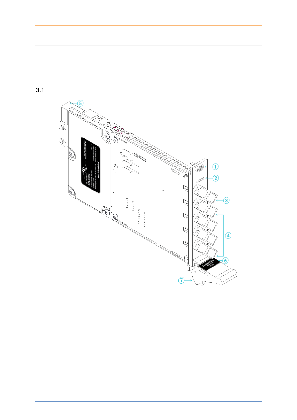
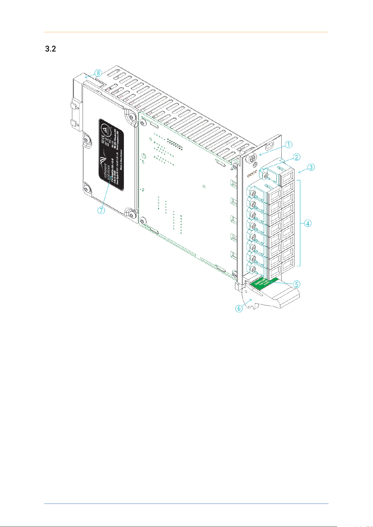
SwitchPXIe Overview & Features- Single Slot Models
Note: Number of common and routing ports will depend on the selected model. SwitchPXIe-1003 shown above.
1
Fastening screw
2
Routing Indicator LED
3
Common Optical port
4
Routing Optical ports
5
PXIe Headers
6
PXIe Module/Optical Connector Information
7
Fastening clip
PXIe Platform Optical Switch Module| SwitchPXIe
Coherent Solutions Ltd. Version 2.01 7
SwitchPXIe Overview & Features- Double Slot Models
Note: Number of common and routing ports will depend on the selected model. SwitchPXIe-1106 shown above.
1
Fastening screw
2
Error Status LED
3
Common Optical port
4
Routing Optical ports
5
PXIe Module/Optical Connector Information
6
Fastening clip
7
SwitchPXIe Module Information
8
PXIe Headers
PXIe Platform Optical Switch Module| SwitchPXIe
Coherent Solutions Ltd. Version 2.01 8
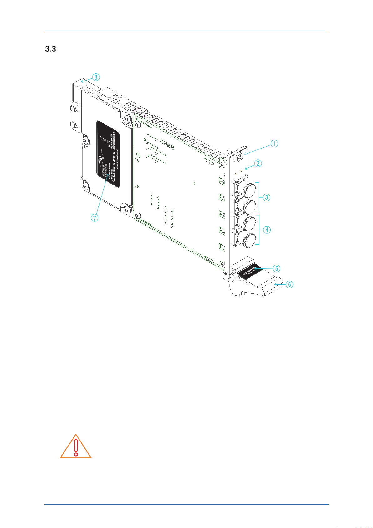
SwitchPXIe Overview & Features- Crossover Modules
1
Fastening screw
2
Routing Indicator LEDs
3
Red Optical ports
4
Blue Optical ports
5
PXIe Module/Optical Connector Information
6
Fastening clip
7
SwitchPXIe Module Information
8
PXIe Headers
IMPORTANT
All Crossover switch modules DO NOT HAVE A PARK STATE. When
plugging optical fibres into the ports or inspecting fibres, ensure that
the optical source is off to prevent user injury.

PXIe Platform Optical Switch Module| SwitchPXIe
Coherent Solutions Ltd. Version 2.01 9
Status LED
The Status LEDs are used to denote the operation state of the SwitchPXIe. The different
colours have slightly different meanings for the different SwitchPXIe models.
3.4.1 For SwitchPXIe-1003 and SwitchPXIe-1103
• Blinking yellow: Indicates initialization on startup.
• All off- Indicates that the SwitchPXIe is in the PARK state (State 0).
• Solid green- Indicates which state the SwitchPXIe is routed to.
• Solid red- Indicates a Switch error. Most often this means an invalid route position.
3.4.2 For SwitchPXIe-1006/1009/1107
• Blinking yellow: Indicates initialization on startup.
• Solid green- Indicates successful initialization and communication.
• Solid red- Indicates a Switch error. Most likely an initialization error at startup.
3.4.3 For SwitchPXIe-1004
The SwitchPXIe-1004 is a 2x2 crossover switch. This means that it has only 2 valid states:
Transmit (T) and Cross.(C) The front panel LEDs on this switch will indicate which state the
switch is in. Further information can be gathered from the colour of the LEDs as such:
• Solid green- Indicates which state the SwitchPXIe is in (default is T)
• Solid red- Indicates there was an error in switching states. Only 1 LED will light up.
PXIe Platform Optical Switch Module| SwitchPXIe
Coherent Solutions Ltd. Version 2.01 10
4 Connecting Optical Input
IMPORTANT
To ensure maximum power and to avoid erroneous readings always
inspect fiber end faces. Make sure they are cleaned as detailed below
before inserting into any port. Coherent Solutions is not responsible for
damage or errors caused by bad fiber cleaning or handling.
CAUTION
The type of optical connectors on the SwitchPXIe module can be found
printed on the front plate of the module. Joining mismatched
connectors will damage the ferrules and fibre faces.
Cleaning and Connecting Optical Fibers
To connect the fiber-optic cable to the port:
1. Inspect the fiber using a fiber inspection microscope. If the fiber is clean, proceed to
connect it to the desired port. If the fiber is dirty, clean it as detailed below.
2. Clean fiber ends as follows:
a Gently wipe the fiber end with a lint-free swab dipped in isopropyl alcohol.
b Use compressed air to dry completely.
c Visually inspect the fiber end to ensure its cleanliness.
3. Carefully align the connector and port to prevent the fiber end from touching the outside
of the port or rubbing against other surfaces. If the connector features a key, ensure that
it is correctly mated into the corresponding notch of the port bulkhead.
4. Push the connector in so that the fiber-optic cable is firmly in place, thus ensuring
adequate contact. If your connector features a screw sleeve, tighten the connector
enough to firmly maintain the fiber in place. Do not over tighten, as this will damage the
fiber and the port bulkhead.
Note: If your fiber-optic cable is not properly aligned and/or connected, you will notice large
signal loss and reflection.
Coherent Solutions uses high quality connectors in compliance with EIA-455-21A standards.
To keep connectors clean and in good condition, Coherent Solutions strongly recommends
inspecting them with a fiber inspection probe before connecting them. Failure to do so will
result in permanent damage to the connectors and degradation of future measurements.
PXIe Platform Optical Switch Module| SwitchPXIe
Coherent Solutions Ltd. Version 2.01 11
5 Handling the SwitchPXIe Module
SwitchPXIe Module Installation
WARNING
DO NOT attempt to remove or adjust any component of the PXIe
chassis while the power is on. Ensure the chassis is powered OFF first,
and that the correct installation and removal procedure detailed herein
is followed.
CAUTION
• Do not remove the SwitchPXIe from the antistatic packaging
until instructed during the following installation procedure.
• The SwitchPXIe is sensitive to ESD. Please be sure to wear a
grounded wrist strap at all times when handling the SwitchPXIe
module to prevent such damage.
• Take care not to handle the connectors on the SwitchPXIe
module, as once they are exposed to skin contact this may
leave corrosive residue which can damage the connector.
1. Shutdown the PXIe chassis.
2. If present, remove the current module or
blanking plate in the intended installation
slot.
3. Carefully remove the SwitchPXIe module
from the antistatic packaging bag it was
shipped in.
Retain the bag for storage of the
SwitchPXIe module.
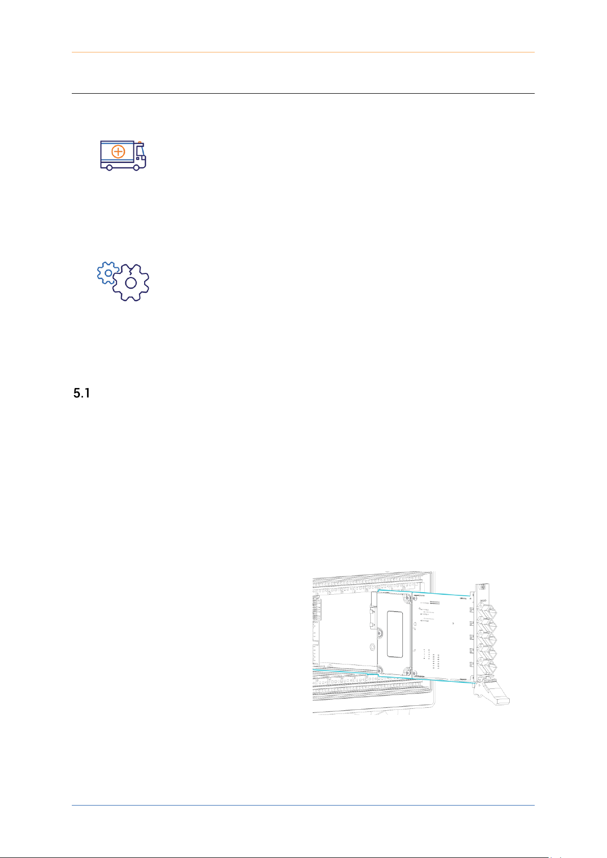
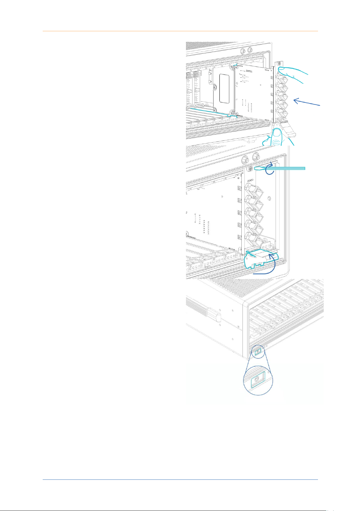
4. Insert the SwitchPXIe module into the
desired slot.
Align the top and bottom lip of the
SwitchPXIe module with the chassis
guide rails. With a firm grip push the
module into the chassis.
PXIe Platform Optical Switch Module| SwitchPXIe
Coherent Solutions Ltd. Version 2.01 12
5. Push the module into the chassis until a
resistance is felt.
This is to confirm the header pins on the
back of the module are properly
connected to the chassis.
6. Secure the module into the chassis by
pulling up on the black locking clip.
A click should be heard when the locking
clip is properly engaged into the front
chassis rail.
Secure the fastening screw with a
screwdriver.
7. Perform a visual check to ensure no
loose items or tools have been left in the
chassis after installation.
Power on the PXIe chassis.
PXIe Platform Optical Switch Module| SwitchPXIe
Coherent Solutions Ltd. Version 2.01 13
SwitchPXIe Module Uninstallation
IMPORTANT
After powering on the PXIe chassis, please wait at least 2 minutes
before attempting to communicate with the instrument. This will allow
the chassis enough time to finish boot procedures and initialize the
communication server.
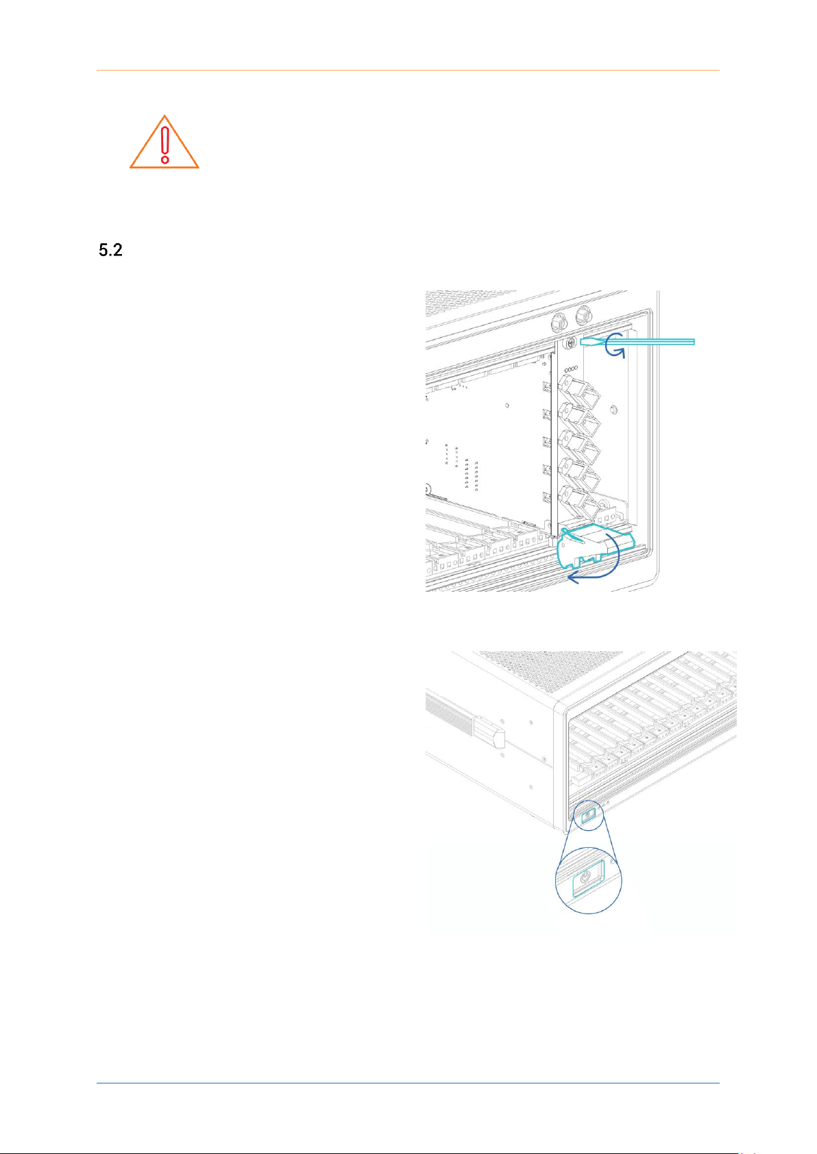
1. Shutdown the PXIe chassis.
2. Unfasten the locking clip on the
SwitchPXIe module. Unscrew the
fastening screw.
Pull out the module from the chassis while
firmly gripping the front plate edges of the
SwitchPXIe module. DO NOT PULL THE
MODULE OUT BY GRIPPING ANY OF THE
CONNECTORS.
3. Insert the SwitchPXIe module in the
antistatic bag it was shipped in. Store
appropriately.
4. Power on the PXIe chassis.
PXIe Platform Optical Switch Module| SwitchPXIe
Coherent Solutions Ltd. Version 2.01 14
6 Software Installation Information
IMPORTANT
The software requires installation on the Controller for the PXIe Chassis
where the CSL Modules will be installed.
Minimum System Requirements: 64bit OS, Windows 7 or above
In order for the PXIe controller to communicate with the SwitchPXIe installed in the chassis,
some software packages are necessary. These software packages are:
• CSLDriverInstaller: Drivers for Coherent Solutions PXIe Modules
• CSLServer: VXI11 server for remote communication
• cohesionUI: Web based Graphical User Interface
Installation Overview
The following is an installation guide of the minimum required NI and CSL resources to install
so that the CSL Modules can be used:
1. Install the CSLDriverInstaller Software Package
2. Install the latest NI Platform Services Software Package (as per Chassis and
Controller)
3. Power off the Chassis.
4. Install all the desired CSL Hardware Modules into the Chassis.
5. Power on the Chassis.
6. Windows Device Manager will list the new CSL Hardware Devices
7. Install the CSLServer Software Package.
8. Restart the Chassis.
Optional:
• Install cohesionUI Software Package
• Restart the Chassis
IMPORTANT
It recommended that you save all work and close any open programs
before attempting to install the required software packages above.
All installation processes may require a system reboot to complete the
installation.
PXIe Platform Optical Switch Module| SwitchPXIe
Coherent Solutions Ltd. Version 2.01 15
7 Windows Driver Installation for CSL Devices
Windows 10 64bit:
1. Locate installer setup.exe in the CSLDriverInstaller folder on the provided media.
2. Allow installation by clicking ‘Yes’ in the User Account Control prompt and proceed
with installing the NI CSL Driver package.
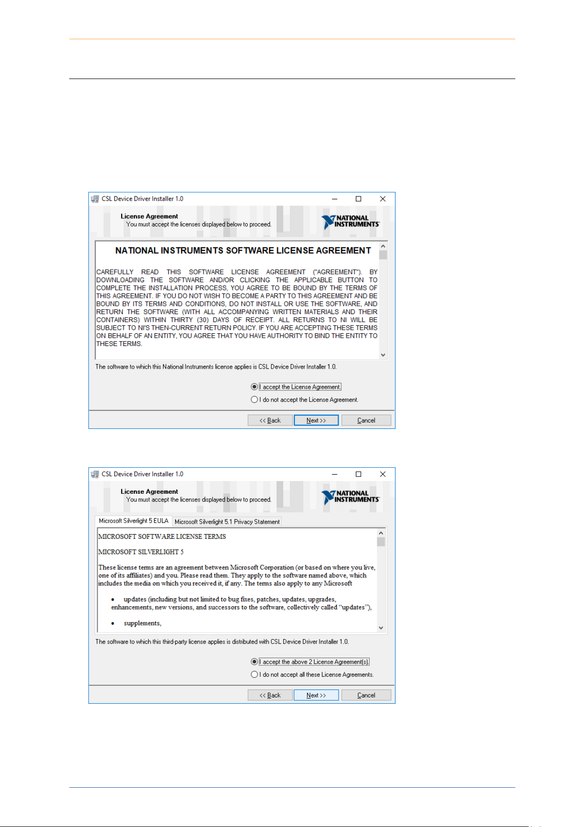
3. Accept the NI License Agreements to continue the installation.
4. Accept the Microsoft License Agreements to continue the installation.
PXIe Platform Optical Switch Module| SwitchPXIe
Coherent Solutions Ltd. Version 2.01 16
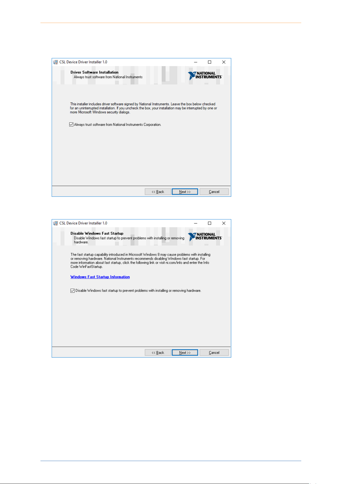
5. Select the Always trust software from National Instruments Corporation option to
allow uninterrupted installation.
6. Disabling Windows fast startup is recommended.
PXIe Platform Optical Switch Module| SwitchPXIe
Coherent Solutions Ltd. Version 2.01 17
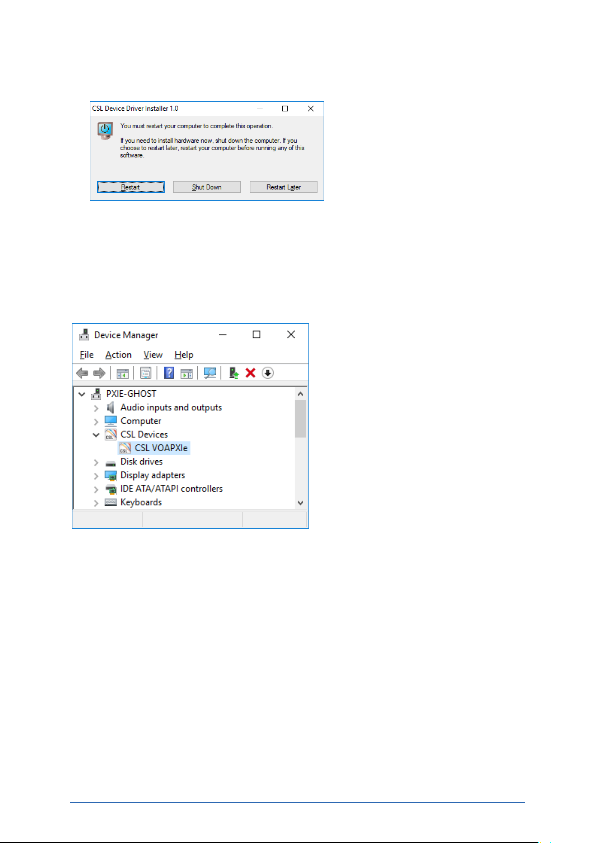
7. Once completed, select the ‘Shut Down’ option in the final prompt to power down the
Chassis. Install the desired CSL PXIe Modules into the Chassis now.
8. Once the new modules are installed, turn on the Chassis.
The Chassis will now install the new drivers for the installed modules and you are able to
install the CSLServer VXI11 service to the Chassis (see the following section).
The modules will show up in device manager under CSL Devices:

PXIe Platform Optical Switch Module| SwitchPXIe
Coherent Solutions Ltd. Version 2.01 18
8 CSL Server Installation
The CSLServer is installed as a Windows Service providing SCPI over a VXI11 compliant
interface.
1. Locate the CSLServer-x.x.x-win32.exe installer and run this as Administrator (you will
be prompted). Allow installation by clicking ‘Yes’ in the UAC prompt.
2. If a previous version of the CSLServer is discovered, the installation will ask for
permission to uninstall the previous version and continue.
3. Once complete, you will be presented with the Welcome screen, click Next to continue

PXIe Platform Optical Switch Module| SwitchPXIe
Coherent Solutions Ltd. Version 2.01 19
4. Proceed with installation by accepting Licence Agreement
5. (Recommended) Leave the default settings for adding the CSLServer installation
location to the system path.

PXIe Platform Optical Switch Module| SwitchPXIe
Coherent Solutions Ltd. Version 2.01 20
6. (Recommended) Accept the default installation destination for the CSLServer package.
7. Choose the location of the shortcuts in the start menu.

PXIe Platform Optical Switch Module| SwitchPXIe
Coherent Solutions Ltd. Version 2.01 21
IMPORTANT
To operate in Multi Chassis Mode, additional hardware modules are
required. The Chassis Mode can be changed at any time, so it is
recommended to select SingleMode until all other configuration
requirements have been met.
8. Installation will continue and then you will be presented with the Chassis Mode
options.
9. Once complete, reboot the Chassis.

PXIe Platform Optical Switch Module| SwitchPXIe
Coherent Solutions Ltd. Version 2.01 22
9 cohesionUI Installation
The cohesionUI will install as a Windows Service providing controls for all the CSL Modules
within a web style application.
1. Run the cohesionUI installation with Administrator privileges.
If there is an installation of a previous version of CSLWebServer present, the cohesionUI
application will uninstall the older version and then proceed with the new version
installation.
After uninstallation, the cohesionUI application will reboot automatically, and then
continue with the installation process.

PXIe Platform Optical Switch Module| SwitchPXIe
Coherent Solutions Ltd. Version 2.01 23
2. Proceed with installation by accepting the License Agreement.
3. Click Next at the Welcome screen to continue the installation.

PXIe Platform Optical Switch Module| SwitchPXIe
Coherent Solutions Ltd. Version 2.01 24
4. (Recommended) Select the Apache option for the web server installation.
5. (Recommended) The dependencies are automatically selected for the installation.

PXIe Platform Optical Switch Module| SwitchPXIe
Coherent Solutions Ltd. Version 2.01 25
6. (Recommended) Click Install to begin the installation in the default location.
7. While installing the required resources, other installers will show progress as they are
called. These will change depending on what is already installed on the Chassis.

PXIe Platform Optical Switch Module| SwitchPXIe
Coherent Solutions Ltd. Version 2.01 26
8. (Apache) When installing and configuring the Apache service, you will be required to
allow the firewall rules.
IMPORTANT

PXIe Platform Optical Switch Module| SwitchPXIe
Coherent Solutions Ltd. Version 2.01 27
9. (Recommended) Once the file copy progress is complete you will require to select a
port number for the cohesionUI to use.
10. Once selected, you will be prompted if the port number chosen is not available,
however if you are informed the port is open for use, the installation can complete.

PXIe Platform Optical Switch Module| SwitchPXIe
Coherent Solutions Ltd. Version 2.01 28
11. Once completed, please reboot the Chassis to enable all the services to restart
automatically.

PXIe Platform Optical Switch Module| SwitchPXIe
Coherent Solutions Ltd. Version 2.01 29
10 CSL Firmware Updater
IMPORTANT
The CSL Firmware Updater utility is available in CSLServer 2.0.10 or later.
While the CSL Firmware Updater is open, all the CSL Services will be
stopped and communication with all the modules will be unavailable.
The CSL Firmware Updater is a Windows GUI utility used to simplify installation of new
Firmware onto the CSL PXIe Modules. The Firmware Updater is installed as part of the
CSLServer package. An icon will be installed in the start menu to allow easy access to run the
tool.
Overview of the Firmware Updater Main Display
The main display of the Firmware Updater tool has the following features:
1
Slot number selection drop down
2
Chassis number selection drop down
3
Chassis mode toggle
4
File selection browser
5
Update button to launch Firmware updater Utility
6
Progress bar
7
Close button to quit Firmware Updater Utility
8
Information panel

PXIe Platform Optical Switch Module| SwitchPXIe
Coherent Solutions Ltd. Version 2.01 30
Downloading the Firmware file
IMPORTANT
In order to use the CSL Firmware Updater, the desired .bex firmware file
must be downloaded from the Coherent Solutions website.
1. Go to https://www.coherent-solutions.com/resources/pxi/
2. Find and download the relevant Firmware file.
Running the CSL Firmware Updater
To run the CSL Firmware Updater:
1. Open the Start menu and navigate to the CSLServer folder.
2. Once open, select the Slot number of the module to update (example is Slot 5).

PXIe Platform Optical Switch Module| SwitchPXIe
Coherent Solutions Ltd. Version 2.01 31
3. Select the Chassis Mode from the toggle button. If operating in MULTI mode, then the
Chassis drop down will be available to edit.
If operating in SINGLE mode, the Chassis drop down will be greyed out. By default the
application starts in SINGLE mode, thus the Chassis selection is disabled.

PXIe Platform Optical Switch Module| SwitchPXIe
Coherent Solutions Ltd. Version 2.01 32
4. Click the File selection browser button (open folder icon) to open the Windows File
Explorer window and select the desired file.
5. Once all valid selections have been made, the Update button will be enabled.
IMPORTANT
The Update procedure will stop the CSLServer. All connections to the
instrument will be lost.
Click the Update button to begin the firmware update procedure. If the application is
closed while the update is in progress, the update will continue in the background but all
status information will be unavailable.

PXIe Platform Optical Switch Module| SwitchPXIe
Coherent Solutions Ltd. Version 2.01 33
6. The progress bar will show the status of the update. Any error codes will also be
displayed in the information panel below the progress bar.
7. During the user selections and primarily after the Update process has been completed,
the information panel will provide information relating to the update procedure.

PXIe Platform Optical Switch Module| SwitchPXIe
Coherent Solutions Ltd. Version 2.01 34
Any errors during the update procedure (usually caused due to incorrect user selections),
will be displayed in the information panel. The error code displayed will remain until a new
update process has been started.
The given example shows the error code from an incorrect (invalid) slot selection. In this
instance there was no module in slot 14 to update.
Once complete the Firmware Updater Utility will restart the CSLServer automatically.

PXIe Platform Optical Switch Module| SwitchPXIe
Coherent Solutions Ltd. Version 2.01 35
11 cohesionUI™
cohesionUI is a graphical user interface (GUI) that makes it simple to control any Coherent
Solutions PXIe module from a PC or mobile device. Its cutting-edge design offers a sleek
modern interface, cross device compatibility, multi instrument control, customizable views
and remote network access.
Finding the IP address
To launch cohesionUI, first determine the IP address of the device. For PXIe the chassis can
either be accessed via remote or local means.
Local access is achieved by running cohesionUI on the embedded PXIe controller module in
the chassis.
Remote access can be achieved from any compatible external device connected to the PXIe
chassis via an ethernet connection.
• For PXIe (local access): Click the Desktop Icon for cohesionUI that was created by the
cohesionUI installer.
• For PXIe (remote access): On the Chassis open a Command Prompt window and type
in ipconfig. Note down the displayed IPv4 Address; this is the IP address of the
chassis.
Launch Google Chrome or Microsoft Edge on the remote client machine, and type in
the host device IP address into the address bar of the browser eg 10.10.10.89.

PXIe Platform Optical Switch Module| SwitchPXIe
Coherent Solutions Ltd. Version 2.01 36
Home
After entering in the IP address of the Chassis and pressing enter, the cohesionUI will be
displayed.
The main landing page of cohesionUI is called the Home page. It will display a graphical
representation of the module arrangement in the PXIe chassis. The blue numbers beside
each module show the slot in which they are installed.
By toggling the Empty Slots button from HIDDEN to SHOWN, the modules will be displayed as
they are connected in the chassis with any empty slots shown. The default mode is to hide
the empty slots.

PXIe Platform Optical Switch Module| SwitchPXIe
Coherent Solutions Ltd. Version 2.01 37
Modules
All the installed modules are displayed on the home screen. To access the controls for a
given module click on the Modules tab.
Alternatively, hovering over the Modules button will bring up a floating dropdown of the
modules installed in the chassis. Controls for a specific module, or a channel in a module can
be accessed by clicking the appropriate dropdown menu item.
For module specific controls please consult the device user manual.

PXIe Platform Optical Switch Module| SwitchPXIe
Coherent Solutions Ltd. Version 2.01 38
Settings
The settings for the cohesionUI can be accessed by either hovering over the Settings button,
or clicking the button. Both of these actions will allow access to the units displayed in the
module controls.
Note: Whenever the chassis is power cycled, cohesionUI will revert back to default unit values
in settings.
In the Settings menu, the step size value can be set. This is the amount by which the
attenuation, frequency or power will increment or decrement by when the + or - buttons are
clicked.

PXIe Platform Optical Switch Module| SwitchPXIe
Coherent Solutions Ltd. Version 2.01 39
Info
The Info button can be clicked at any time to pull up a display bar on the right side of the
screen This will show the chassis mode, manufacturer, model, serial number of the chassis,
the cohesionUI version number and the VXI11/SCPI Server version running on the chassis.

PXIe Platform Optical Switch Module| SwitchPXIe
Coherent Solutions Ltd. Version 2.01 40
12 SwitchPXIe control with cohesionUI
To control the SwitchPXIe through cohesionUI, click the desired module installed in the
chassis. Alternatively, hovering over the Modules menu button on the left will bring up a
dropdown that the SwitchPXIe module can also be selected from.
After clicking the desired SwitchPXIe module, its control page is displayed. All information
relating to the module such as model number, serial number and firmware versions are
displayed in the top right corner of the window.
The SwitchPXIe is always in a PARK state by default. When in PARK the SwitchPXIe will act
like an optical terminator.

PXIe Platform Optical Switch Module| SwitchPXIe
Coherent Solutions Ltd. Version 2.01 41
To route the SwitchPXIe to the desired port, click the Port number, eg PORT 2.
The SwitchPXIe can route the light very quickly, however cohesionUI takes a few seconds to
update the displayed routing.
Therefore, there is a slight delay between re-routing the SwitchPXIe and the UI updating the
window. A blue tick mark will be displayed beside the current routed port.

PXIe Platform Optical Switch Module| SwitchPXIe
Coherent Solutions Ltd. Version 2.01 42
13 Programming Guide
Introduction
Remote communication with the CSLServer is achieved through the Standard Commands for
Programmable Instruments (SCPI). Support for VISA I/O API over TCP/IP is provided by the
VXI-11 compliant CSLServer. With VISA communication drivers installed on the client, the
implementation of VISA programming within environments such as MATLAB becomes
available. This guide provides general information on the commands available to
communicate with the CSLServer remotely using the VISA I/O.
Programming Conventions
This section details the programming and measurement conventions to follow while
executing the commands for the CSLServer.
Parameter
Default Unit
Alternative Units
Power
DBM
DBM
Frequency
HZ
THZ, GHZ, MHZ, KHZ
Frequency Fine
HZ
THZ, GHZ, MHZ, KHZ
Wavelength
NM
M, PM
Argument
Data Format
<wsp>
Specifies whitespace character (0116 – 0916, 0B16 – 2016).
<value>
Is numerical data, an integer, a decimal, exponential (10e-9 or 5.8e6)
or string
[VALUE1|VALUE2]
A parameter choice. The ‘|’ separates the unique parameters
available, only one of the choices can be used. In the example, either
the input parameter [VALUE1] or [VALUE2] can be used, but not both.
Some commands may have more than two choices available.
This parameter can be omitted where the command has a default
defined in the command description.
IMPORTANT
In NI-MAX a RIO interface will show up, however there are no
communication methods available or implemented on this interface.
Coherent Solutions Modules are ONLY accessible through the VISA
TCPIP INSTR interface provided by the CSLServer installed on the
system.

PXIe Platform Optical Switch Module| SwitchPXIe
Coherent Solutions Ltd. Version 2.01 43
Index Addressing of Modules (slot, source) and Units (channel)
When executing commands, it is almost always necessary to provide the index of a specific
SwitchPXIe module or an index of a specific installed unit.
For the commands that require index values:
• <c>: is the chassis index in which the specific blade module is installed; this is an
integer, inclusive of 0.
• <n>: is the slot (or source) index of the specific blade module, this is an integer, <1 to
18>
• <m>: is the channel index of a specific unit in the module, this is an integer, <1, 2 >.
Message Queues
Information is exchanged in the form of messages. These messages are held in input and
output queues.
The output queue stores responses to query commands. The CSLServer transmits any data
in the output queue when a read request is received. Unless explicitly specified otherwise in
the command description, all output response data is transmitted in ASCII format.
Common System Command Summary
Common Commands
Description
*CLS
*IDN?
*OPC?
*OPT?
-Clear Status command
-Query the chassis identification
-Query the Operation Complete Status
-Query the modules managed by the CSLServer

PXIe Platform Optical Switch Module| SwitchPXIe
Coherent Solutions Ltd. Version 2.01 44
Common System Command Descriptions
Command
*CLS
Syntax
*CLS
Description
Clear Status command
Parameters
None
Response
None
Example
*CLS
Command
*IDN?
Syntax
*IDN?
Description
Query the chassis identification
Parameters
None
Response
Comma separated string with the <manufacturer>,<server name>,<chassis controller
name>,<server version>
Example
*IDN? -> Coherent Solutions,CSLServer,PXIE-8133,FW2.0.15
Command
*OPC?
Syntax
*OPC?
Description
Query the Operation Complete Status
Parameters
None
Response
1 is returned if all the modules installed in the chassis are ready to execute
commands
0 is returned if any module installed in the chassis still has a command to
execute in the input queue
Example
*OPC? -> 0
Command
*OPT?
Syntax
*OPT?
Description
Query the modules managed by the CSLServer
Parameters
None
Response
Response will be a comma separated string of the installed modules in the chassis
Example
*OPT? -> ,SwitchPXIe-1004-1-FA,LaserPXIe-1001-4-FC,,VOAPXIe-1001-2-FA
,,,,O2EPXIe-1001-1-FC,,,,,,,,,

PXIe Platform Optical Switch Module| SwitchPXIe
Coherent Solutions Ltd. Version 2.01 45
Specific Command Summary
Slot commands
Description
:SLOT<n>
:OPC?
:OPTions?
:IDN?
-Query the status of the Operation Complete bit
-Query the modules installed on the slot
-Query the Identifier for the slot; returns the
manufacturer, part number, serial
number, hardware and firmware
versions
Configuration commands
Description
ROUTe<n>
:ERROR?
:CHANnel<m>
:ERROR?
:STATE/?
-Query the error status of the SwitchPXIe
-Query the error status of the specified channel
of the SwitchPXIe
-Set or query the routing state of the SwitchPXIe

PXIe Platform Optical Switch Module| SwitchPXIe
Coherent Solutions Ltd. Version 2.01 46
Specific Command Descriptions
13.5.1 Slot Commands
Command
:SLOT<n>:OPC?
Syntax
:SLOT<n>:OPC?
Description
Query the status of the Operation Complete bit
Parameters
None
Response
1 is returned if the module is ready to execute a new operation
0 is returned if the module is busy
Example
SLOT1:OPC? -> 1
Command
:SLOT<n>:OPTions?
Syntax
:SLOT<n>:OPTions?
Description
Query the modules installed on the slot
Parameters
None
Response
The response will be a comma separated string of detectors installed in the
SwitchPXIe. If a module is not installed in a channel, it will not return any
identification string.
Example
SLOT3:OPT? -> 1,,,
Command
:SLOT<n>:IDN?
Syntax
:SLOT<n>:IDN?
Description
Query the Identifier for the slot; returns the manufacturer, part number, serial
number, hardware and firmware versions.
Parameters
None
Response
Comma separated string containing the <manufacturer>, <part number>, <serial
number>,<hardware version><firmware version>
Example
SLOT1:IDN? -> Coherent Solutions,SwitchPXIe-1401-4-FC,CSL-180101,
HW0.01FW0.02
Note: Hardware and firmware versions are combined and not separated by a comma

PXIe Platform Optical Switch Module| SwitchPXIe
Coherent Solutions Ltd. Version 2.01 47
13.5.2 Configuration Commands
Command
:ROUTe<n>:ERROR?
Syntax
:ROUTe<n>:ERROR?
Description
Query the error status of the SwitchPXIe
Parameters
None
Response
The response of an integer value representing a bitmask of switch errors.
8 Switch D(4) reports an error
4 Switch C(3) reports an error
2 Switch B(2) reports an error
1 Switch A (1) reports an error
0 There are no reported errors
Example
ROUT1:ERROR? -> 1
Command
:ROUTe<n>:CHANnel<m>:ERROR?
Syntax
:ROUTe<n>:CHANnel<m>:ERROR?
Description
Query the error status of the specified channel of the SwitchPXIe
Parameters
None
Response
1 Switch reporting an error
0 No error on switch
Example
ROUT1:CHANA:ERROR? -> 0
Command
:ROUTe<n>:CHANnel<m>:STATE
Syntax
:ROUTe<n>:CHANnel<m>:STATE<wsp><value>
Description
Set the routing state of the SwitchPXIe
Parameters
<value>: A valid number representing the routing state of the switch
Response
None
Example
ROUT1:CHANA:STATE 2
Command
:ROUTe<n>:CHANnel<m>:STATE?
Syntax
:ROUTe<n>:CHANnel<m>:STATE?<wsp>[SET|ACT|ACTUAL|ALL]
Description
Query the routing state of the SwitchPXIe
Parameters
SET: Returns the set routing state
ACT|ACTUAL: Returns the current position of the switch routing state
ALL: Returns all the above values in a comma separated string
Response
None
Example
ROUT1:CHANA:STATE? -> 2, 2

PXIe Platform Optical Switch Module| SwitchPXIe
Coherent Solutions Ltd. Version 2.01 48
Multi Chassis Mode Operation
13.6.1 NI-MAX
In the example shown below, there are two chassis connected via the PXIe-8834 to PXIe-8381
connection. Chassis #2 has the controller running CSLServer, and Chassis #3 is the ‘extended’
chassis.
IMPORTANT
The CSLServer does not manage the chassis numbers. These are
controlled by the NI Platform Services (and through NI-MAX).
IMPORTANT
Even if the CSLServer is in Multi Chassis mode, if a chassis is
connected but has no installed modules, it will not show up when
*OPT? is run.

PXIe Platform Optical Switch Module| SwitchPXIe
Coherent Solutions Ltd. Version 2.01 49
13.6.2 SCPI Multi Chassis Commands
Multiple chassis can be connected together to operate in Multi Chassis Mode. In order to
operate in Multi Chassis Mode, CSLServer must be version 1.02.06 or later.
Command
:SYSTEM:CHASSIS?
Syntax
:SYSTEM:CHASSIS?<wsp>[LIST|MODE]
Description
Query the Chassis Mode configuration
Parameters
None
Response
LIST: Returns a comma separated list of valid chassis index numbers discovered
by the CSLServer. These are chassis that have modules installed.
MODE: Returns the current Chassis Mode the CSLServer is operating in (SINGLE or
MULTI)
None: Returns the number of chassis managed by the CSLServer. If operating in
SINGLE mode, this will always return 1
Example
In Single chassis mode:
SYSTEM:CHASSIS? -> 1
SYSTEM:CHASSIS? LIST -> 0
SYSTEM:CHASSIS? MODE -> SINGLE
In Multi chassis mode:
SYSTEM:CHASSIS? -> 2
SYSTEM:CHASSIS? LIST -> 2,3
SYSTEM:CHASSIS? MODE -> MULTI
Command
:SYSTEM:CHASSIS
Syntax
:SYSTEM:CHASSIS<wsp>[SINGLE|MULTI]
Description
Set the Chassis Mode configuration
Parameters
SINGLE: Set the CSLServer to operate in SINGLE Chassis Mode
MULTI: Set the CSLServer to operate in MULTI Chassis Mode
Response
None
Example
SYSTEM:CHASSIS SINGLE
In Multi chassis mode, all the commands given above in the Specific Command Summary will
still work, but they must be prefixed with :CHASSIS<c>.
Common Command Example:
Single Chassis Mode
SLOT3:IDN?
Multi Chassis Mode
CHASSIS1:SLOT3:IDN?
Specific Command Example:
Single Chassis Mode
SENS3:CHAN2:POW? MAX
Multi Chassis Mode
CHASSIS1 SENS3:CHAN2:POW? MAX
IMPORTANT
Changing the CSLServer Chassis Mode will rediscover all Chassis and
installed modules.

PXIe Platform Optical Switch Module| SwitchPXIe
Coherent Solutions Ltd. Version 2.01 50
14 Maintenance
To help ensure long, trouble-free operation:
• Always inspect fiber-optic connectors before using them and clean them if necessary.
• Keep the module free of dust.
• Store module at room temperature in a clean and dry area. Keep the unit out of direct
sunlight.
• Avoid high humidity or significant temperature fluctuations.
• Avoid unnecessary shocks and vibrations.
• If any liquids are spilled on or into the module, power off the chassis immediately.
Remove the SwitchPXIe and allow to dry completely.
WARNING
The use of controls, adjustments and procedures other than those
specified herein may result in exposure to hazardous situations or
impair the protection provided by this unit.

PXIe Platform Optical Switch Module| SwitchPXIe
Coherent Solutions Ltd. Version 2.01 51
NOTICE
通告
CHINESE REGULATION ON RESTRICTION OF HAZARDOUS SUBSTANCES
中国关于危害物质限制的规定
NAMES AND CONTENTS OF THE TOXIC OR HAZARDOUS SUBSTANCES OR ELEMENTS
CONTAINED IN THIS COHERENT SOLUTIONS PRODUCT
包含在本 COHERENT SOLUTIONS 产品中的有毒有害物质或元素的名称和含量
O
Indicates that this toxic or hazardous substance contained in all of the homogeneous materials
for this part is below the limit requirement in SJ/T11363-2006
表示该有毒有害物质在该部件所有均质材料中的含量均在 SJ/T11363-2006 标准规定的限量要求以
下。
X
Indicates that this toxic or hazardous substance contained in at least one of the homogeneous
materials used for this part is above the limit requirement in SJ/T11363-2006
表示该有毒有害物质至少在该部件的某一均质材料中的含量超出 SJ/T11363-2006 标准规定的限量
要求。
Part Name
部件名称
Toxic or hazardous Substances and Elements
有毒有害物质和元素
Lead
铅
(Pb)
Mercury
汞
(Hg)
Cadmium
镉
(Cd)
Hexavalent
Chromium
六价铬
(Cr VI)
Polybrominated
biphenyls
多溴联苯
(PBB)
Polybrominated
diphenyl ethers
多溴二苯醚
(PBDE)
Enclosure
外壳
O O O O O
O
Electronic and
electrical sub-
assembly
电子和电子组件
X O X O X
X
Optical
sub-assemblya
光学组件
a
X O O O O
O
Mechanical
sub-assemblya
机械组件
a
O O O O O
O
MARKING REQUIREMENTS 标注要求
Product
产品
Environmental protection use period (years)
环境保护使用期限(年)
Logo
标志
This Coherent Solutions
product
本 Coherent Solutions 产品
10
Battery
a
电池
a
5
a. If applicable.
如果适用

PXIe Platform Optical Switch Module| SwitchPXIe
Coherent Solutions Ltd. Version 2.01 52
KCC INFORMATION
Product
KCC Registration No.
Logo
SwitchPXIe-XXXX-XX
R-R-Csn-SwitchPXIe

PXIe Platform Optical Switch Module| SwitchPXIe
Coherent Solutions Ltd. Version 2.01 53
15 Technical Support
Contacting the Technical Support Group
To obtain after-sales service or technical support for this product, contact Coherent Solutions.
The Technical Support Group is available to take your calls from Monday to Friday, 9:00 a.m.
to 5:00 p.m. (New Zealand Time).
Technical Support Group
Tel.: +64 9 478 4849
Fax: +64 9 478 4851
support@coherent-solutions.com
To accelerate the process, please have information such as the name and the serial number
(see the product identification label), as well as a description of your problem, close at hand.
You may also be requested to provide software and module version numbers. This
information, as well as technical support contact information, can be found in the ‘About’
window.
Transportation
Maintain a temperature range within specifications when transporting the unit.
Transportation damage can occur from improper handling. The following steps are
recommended to minimize the possibility of damage:
• Pack the module in its original packing material when shipping.
• Avoid high humidity or large temperature fluctuations.
• Keep the module out of direct sunlight.
• Avoid unnecessary shocks and vibrations.

PXIe Platform Optical Switch Module| SwitchPXIe
Coherent Solutions Ltd. Version 2.01 54
16 Warranty
General Information
Coherent Solutions Ltd. (Coherent Solutions) warrants this equipment against defects in
material and workmanship for a period of one year from the date of original shipment.
Coherent Solutions also warrants that this equipment will meet applicable specifications
under normal use.
During the warranty period, Coherent Solutions will, at its discretion, repair, replace, or issue
credit for any defective product, as well as verify and adjust the product free of charge should
the equipment need to be repaired or if the original calibration is erroneous. If the equipment
is sent back for verification of calibration during the warranty period and found to meet all
published specifications, Coherent Solutions will charge standard calibration fees.
THIS WARRANTY IS IN LIEU OF ALL OTHER WARRANTIES EXPRESSED, IMPLIED, OR
STATUTORY, INCLUDING, BUT NOT LIMITED TO, THE IMPLIED WARRANTIES OF
MERCHANTABILITY AND FITNESS FOR A PARTICULAR PURPOSE. IN NO EVENT SHALL
COHERENT SOLUTIONS BE LIABLE FOR SPECIAL, INCIDENTAL, OR CONSEQUENTIAL
DAMAGES.
Liability
Coherent Solutions shall not be liable for damages resulting from the use of the product, nor
shall be responsible for any failure in the performance of other items to which the product is
connected or the operation of any system of which the product may be a part.
Coherent Solutions shall not be liable for damages resulting from improper usage,
transportation or unauthorized modification of the product, its accompanying accessories
and software.
Exclusions
Coherent Solutions reserves the right to make changes in the design or construction of any of
its products at any time without incurring obligation to make any changes whatsoever on
IMPORTANT
Keep this manual close at hand as it contains important details about
your product.
IMPORTANT
The warranty can become null and void if:
• The unit has been tampered with, repaired, or worked upon by
unauthorized individuals or non-Coherent Solutions personnel.
• The warranty sticker has been removed.
• The unit has been opened, other than as explained in this guide.
• The unit serial number has been altered, erased, or removed.
• The unit has been misused, neglected, or damaged by accident.

PXIe Platform Optical Switch Module| SwitchPXIe
Coherent Solutions Ltd. Version 2.01 55
units purchased. Accessories, including but not limited to fuses, pilot lamps, batteries and
universal interfaces (EUI) used with Coherent Solutions products are not covered by this
warranty.
This warranty excludes failure resulting from: improper use or installation, normal wear and
tear, accident, abuse, neglect, fire, water, lightning or other acts of nature, causes external to
the product or other factors beyond the control of Coherent Solutions.
Certification
Coherent Solutions certifies that this equipment met its published specifications at the time
of shipment from the factory.
Service and Repairs
Coherent Solutions commits to providing product service and repair for five years following
the date of purchase.
To send any equipment for service or repair:
1. Contact Coherent Solutions, contact details are on the back cover. Support personnel
will determine if the equipment requires service, repair, or calibration.
2. If possible, back up your data before sending the unit for repair.
3. Pack the equipment in its original shipping material. Be sure to supply a statement or
report fully detailing the defect and the conditions under which it was observed.
4. Return the equipment, prepaid, to Coherent Solutions.
Note: A test setup fee will apply to any returned unit that, after test, is found to meet the
applicable specifications.
After repair, the equipment will be returned with a repair report. If the equipment is not under
warranty, you will be invoiced for the cost appearing on this report. Coherent Solutions will
pay return-to-customer shipping costs for equipment under warranty. Shipping insurance is
at your expense.
IMPORTANT
Coherent Solutions will charge a fee for replacing optical connectors
that were damaged due to misuse or bad cleaning.

2.01
 Loading...