

Page 1
Page 2

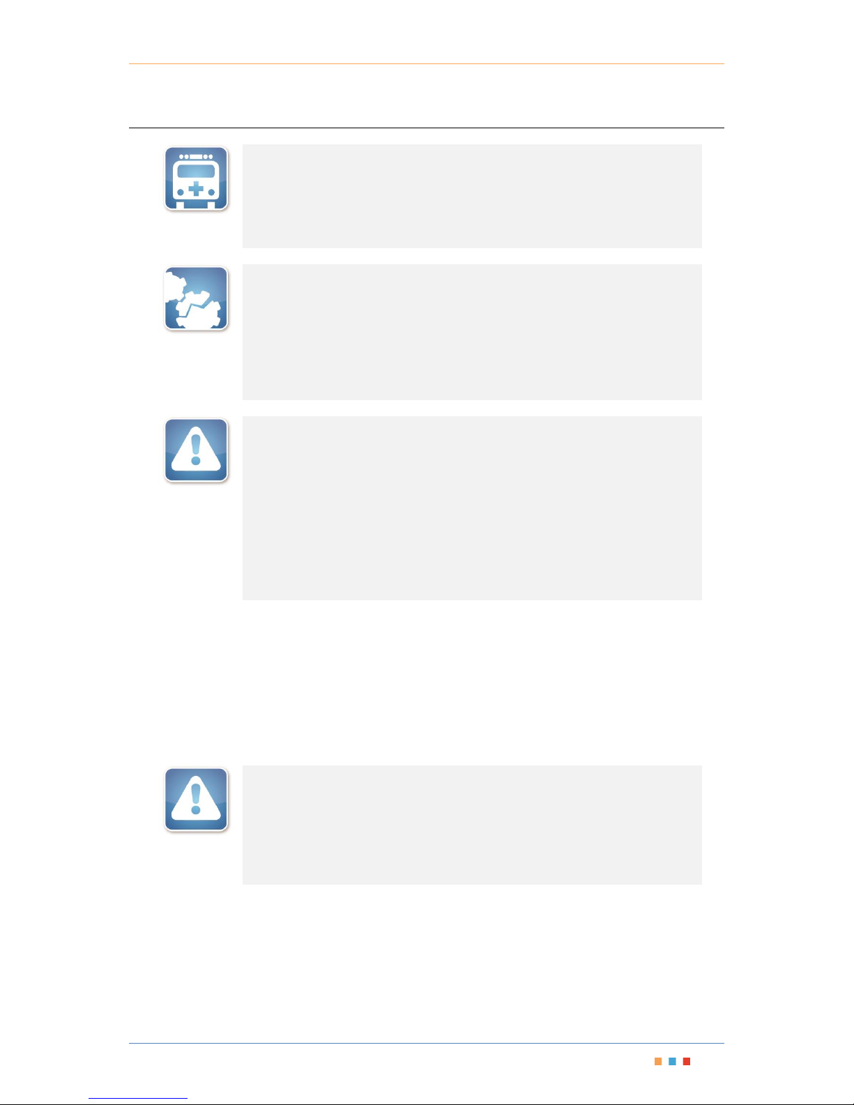
Modular Test Platform | MTPmini
i
Copyright © 2017 Coherent Solutions Ltd. All rights reserved. No part of this publication may be reproduced,
stored in a retrieval system or transmitted in any form, be it electronically, mechanically, or by any other
means such as photocopying, recording or otherwise, without the prior written permission of Coherent
Solutions Ltd. (Coherent Solutions).
Information provided by Coherent Solutions is believed to be accurate and reliable.
However, no responsibility is assumed by Coherent Solutions for its use nor for any infringements of patents or
other rights of third parties that may result from its use. No license is granted by implication or otherwise
under any patent rights of Coherent Solutions.
The information contained in this publication is subject to change without notice.
Trademarks
Coherent Solutions’ trademarks have been identified as such. However, the presence or absence of such
identification does not affect the legal status of any trademark.
Units of Measurement
Units of measurement in this publication conform to SI standards and practices.
Version Number: V1
Page 3

Modular Test Platform | MTPmini
ii
Contents
1 Conventions .............................................................................................................. 1
2 Safety Information ..................................................................................................... 2
3 Introducing the MTPmini Modular Platform ............................................................... 3
4 Features .................................................................................................................... 4
5 Hardware Installation ................................................................................................ 5
5.1 Connections for Remote Operation ...................................................................................................... 5
5.2 Connecting the Ethernet (recommended) ............................................................................................ 5
5.3 Connecting the USB (optional) .............................................................................................................. 5
6 Installing a Blade Expansion Module .......................................................................... 7
7 Removing a Blade Expansion Module ....................................................................... 10
8 Operating the MTPmini ........................................................................................... 13
8.1 Output Enable/Disable ........................................................................................................................ 13
8.2 Powering On/Off the MTPmini ........................................................................................................... 13
8.3 Local Control Touch Screen Graphical User Interface ......................................................................... 13
8.3.1 Navigating within the touchscreen LCD .......................................................................................... 13
8.3.2 Changing Numerical Values ............................................................................................................ 14
8.3.3 Changing Numerical Units .............................................................................................................. 14
8.3.4 Changing Step Size .......................................................................................................................... 15
8.3.5 Viewing or Changing the Network Settings .................................................................................... 15
8.3.6 Orientation Settings ........................................................................................................................ 15
8.4 Remote Operation of the MTPmini ..................................................................................................... 16
8.4.1 Web Graphical User Interface......................................................................................................... 16
8.4.2 Test Instrument Manager Software ................................................................................................ 16
8.4.3 Programming using Virtual Instrument Software Architecture (VISA) ........................................... 16
9 Installing the Software ............................................................................................. 17
9.1 Client System Minimum Requirements .............................................................................................. 17
9.2 Test Instrument Manager Software Installation ................................................................................. 17
10 Maintenance ........................................................................................................ 18
11 Technical Support ................................................................................................. 20
11.1 Contacting the Technical Support Group ............................................................................................ 20
11.2 Transportation .................................................................................................................................... 20
12 Warranty ............................................................................................................. 21
12.1 General Information ............................................................................................................................ 21
12.2 Liability ................................................................................................................................................ 21
12.3 Exclusions ............................................................................................................................................ 21
12.4 Certification ......................................................................................................................................... 22
12.5 Service and Repairs ............................................................................................................................. 22
Page 4

Modular Test Platform | MTPmini
iii
Page 5

Modular Test Platform | MTPmini
Coherent Solutions | MTPmini (V1) 1
1 Conventions
Before using the instrument described in this manual, you should understand the following conventions:
WARNING
Indicates a potentially hazardous situation which, if not avoided, could result in
death or serious injury. Do not proceed unless you understand and meet the
required conditions.
CAUTION
Indicates a potentially hazardous situation which, if not avoided, may result in
minor or moderate injury. Do not proceed unless you understand and meet the
required conditions.
CAUTION
Indicates a potentially hazardous situation which, if not avoided, may result in
component damage. Do not proceed unless you understand and meet the required
conditions.
IMPORTANT
Refers to information about this product you should not overlook.
Page 6

Modular Test Platform | MTPmini
Coherent Solutions | MTPmini (V1) 2
2 Safety Information
WARNING
This instrument must be used with an approved IEC cable with an EARTH
terminal. Do not attempt to use this instrument without a proper earth
terminal, doing so may lead to a hazardous condition and/or damage to the
equipment.
Do not install or terminate fibers while a light source is active. Care must be
taken to ensure that the instrument has been turned OFF before inspecting
the end face(s) of the instrument, or any optical patch cords connected to this
instrument. Never look directly into a live fiber and ensure that your eyes are
protected at all times.
The use of controls, adjustments and procedures other than those specified
herein may result in exposure to hazardous situations or impair the protection
provided by this unit.
CAUTION
The MTPmini is equipped with fans for thermal regulation. Please ensure that
there is at least a 15 cm clear space between the sides of the instrument and
any surrounding objects.
IMPORTANT
For electromagnetic compatibility, this instrument is a Class A product. It is
intended for use in an industrial environment. There may be potential
difficulties in ensuring electromagnetic compatibility in other environments,
due to conducted as well as radiated disturbances.
When you see the following symbol on your unit , make sure that you
refer to the instructions provided in your user documentation. Ensure that you
understand and meet the required conditions before using your product.
The AC mains socket is located on the back panel of the instrument. Above this
socket there is a mains power isolation switch. Once you have connected the
mains AC power this switch is used to power on and off the MTPmini.
Page 7

Modular Test Platform | MTPmini
Coherent Solutions | MTPmini (V1) 3
3 Introducing the MTPmini Modular Platform
The MTPmini is a compact benchtop chassis with 2 Blade bays and touchscreen for stand-alone operation.
Harness the flexibility and connectivity of the MTP platform in a convenient form factor and customize it to
meet your specific requirements.
Figure 1 - Coherent Solutions MTPmini - Modular Platform
All MTP platforms connected to the
network can be managed remotely from
a single client using the simple and
intuitive ‘Test Instrument Manager’
software interface.
Alternatively, VISA programming
environments such as MATLAB can also
be implemented to integrate with
existing test software or data collection
procedures.
Figure 2 - Test Instrument Manager Software
Page 8
Modular Test Platform | MTPmini
Coherent Solutions | MTPmini (V1) 4
4 Features
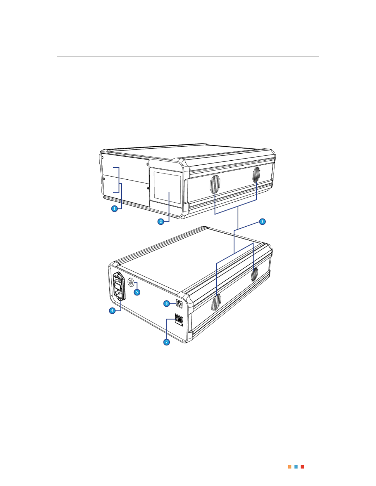
MTPmini Front Panel
1. Blade Expansion Slots (2 Bays)
2. Touchscreen LCD
3. Thermal Regulation Vents (4)
MTPmini Back Panel
4. Mains Power Inlet and Switch
5. Laser Interlock (Output Enable/Disable) Key
6. USB Connection
7. Ethernet Connection
Page 9

Modular Test Platform | MTPmini
Coherent Solutions | MTPmini (V1) 5
5 Hardware Installation
This section details the hardware connections required to setup the MTPmini instrument. Depending on the
hardware setup you are using, not all of the following connections may be required.
5.1 Connections for Remote Operation
The recommended form of communication between any client PC and the MTPmini is via TCP/IP over the
Ethernet. By default the MTPmini is set to obtain an IP address automatically from a DHCP server. If there is no
DHCP server on your network, you will have to configure a static IP for the MTPmini using the USB connection
web interface.
For both USB and Ethernet connections to the instrument please insure that your Firewall settings are
configured such that the instrument can be found by your PC.
If an Ethernet network is not available a dedicated client PC can be used. This dedicated client PC will require
an available USB 2.0 port.
5.2 Connecting the Ethernet (recommended)
Connect the MTPmini Ethernet port to either:
1. The Ethernet Hub of your network to allow any network client the ability to connect remotely.
2. The Ethernet port of a dedicated client PC (this PC being the only client to have remote access) using:
2a. an Ethernet cross-over cable
2b. Ethernet patch cables and small network hub
5.3 Connecting the USB (optional)
To perform administrative tasks such as configuration of the network settings, the USB connection is required.
You may also require use of the USB as a TCP/IP connection if no alternative Ethernet connection is available.
IMPORTANT
You may only have one MTPmini connected via the USB at any time. If
connections to more than one MTPmini are required, an Ethernet network
must be used.
The IP Addressing described below is for the USB network connection.
The IP address for the MTPmini is 192.168.100.201
Windows 7 and Windows 8
1. Connect a USB cable (type male A to male B) between the USB 2.0 port at the back of the MTPmini and
any available USB 2.0 port on the client PC.
2. Once connected, Windows will automatically install the drivers for the USB Ethernet connection. If the
drivers do not automatically install, please refer to the Manual Driver Installation instructions steps 1 to 9
below to install the USB driver.
3. The units USB connection has a static IP address of 192.168.100.201, subnet mask 255.255.255.0
4. The USB Ethernet is now configured.
Page 10

Modular Test Platform | MTPmini
Coherent Solutions | MTPmini (V1) 6
Manual Driver Installation
1. In response to the ‘Can Windows connect to Windows Update to search for software?’ select ‘No, not this
time’ and click Next.
2. Select ‘Install from a list or specific location (Advanced)’ and click Next.
3. Select ‘Don't search. I will choose the driver to install’ and click Next.
4. Click the ‘Have Disk’ button.
5. Click the ‘Browse’ button and locate the oem31.inf file, which can be found in the drivers folder within the
supplied installation media. Click Next to continue.
6. Click ‘Continue Anyway’ when prompted that the driver has not verified its compatibility with Windows.
7. If prompted that ‘The file 'usb8023x.sys' on Windows driver cabinet is needed’, click the ‘Browse’ button
and locate the file inside the drivers folder within the supplied installation media and click OK to continue.
8. The units USB connection has a static IP address of 192.168.100.201, subnet mask 255.255.255.0
9. The USB Ethernet is now configured.
Page 11
Modular Test Platform | MTPmini
Coherent Solutions | MTPmini (V1) 7
6 Installing a Blade Expansion Module
WARNING
DO NOT attempt to remove or adjust any component of the MTPmini while the
power is on. Make sure you follow the correct procedures below and power down
the MTPmini first.
CAUTION
Do not remove the Blade from the antistatic packaging until instructed during
the following installation procedure.
The Blade is sensitive to ESD. Please be sure to wear a grounded wrist strap at
all times when handling the Blade module to prevent such damage.
Take care not to handle the connector on the Blade module once they are
exposed as this may leave corrosive residue which can damage the connector.
Note: You will need a Phillips and Slot screwdriver to both unfasten the blanking module and secure the new
module in place.
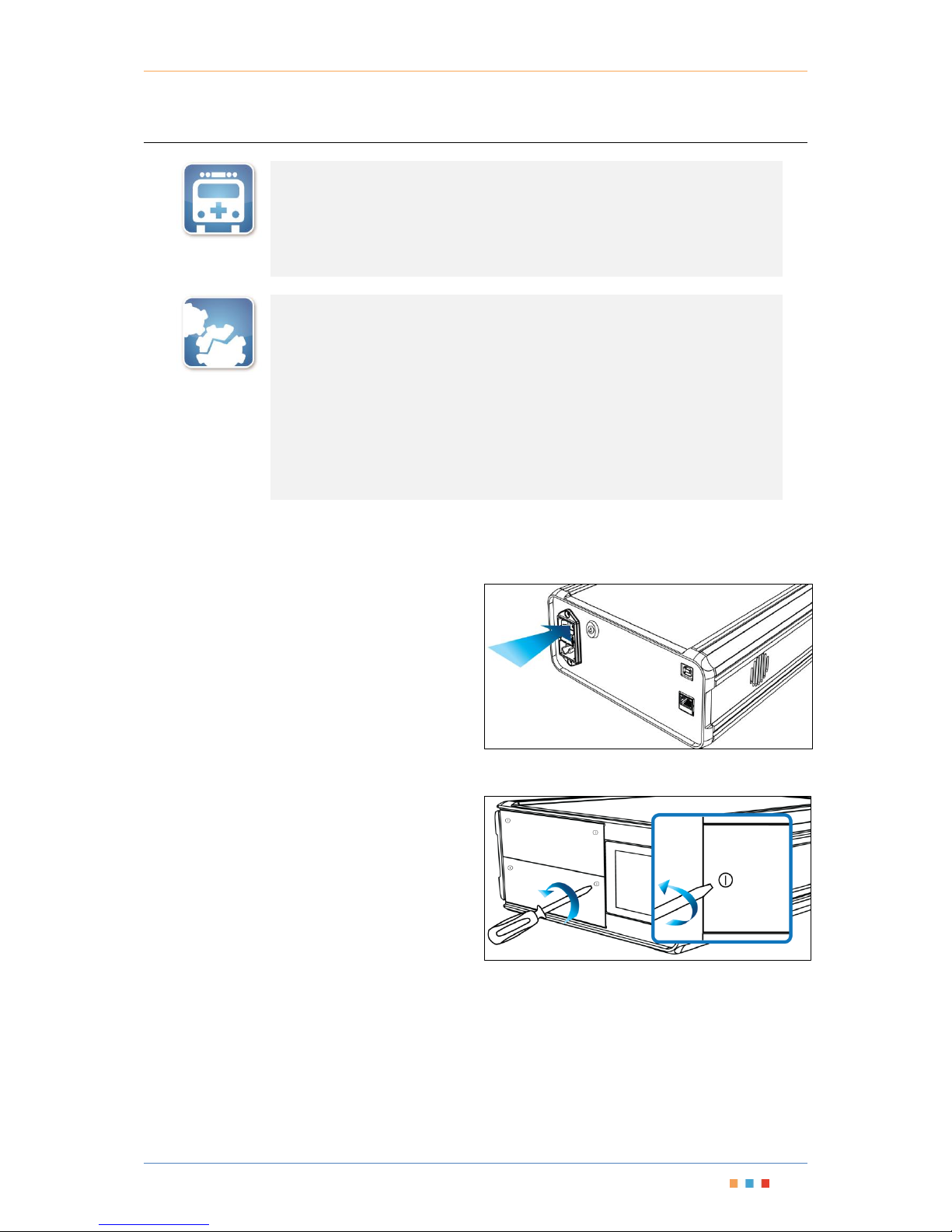
Power down the MTPmini
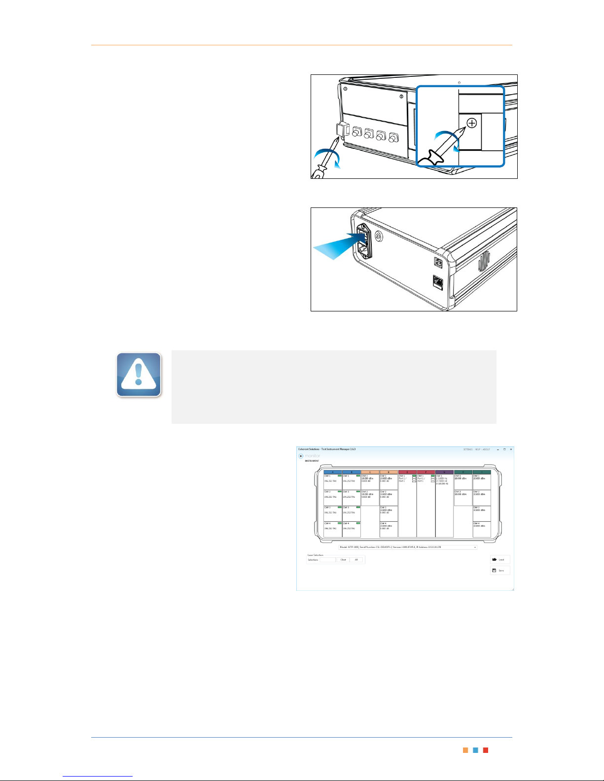
1. Press the Power On/Off switch to turn the
instrument off.
Figure 3 - Turn Off Power
Remove the blanking module
2. To remove the blanking module of the desired
slot, loosen the captive screws on the top and
bottom of the blanking module. Do not attempt
to remove the screws completely as they are
designed to stay inside the front plate of the
module.
Figure 4 - Unfasten screw under Release Latch
Page 12
Modular Test Platform | MTPmini
Coherent Solutions | MTPmini (V1) 8
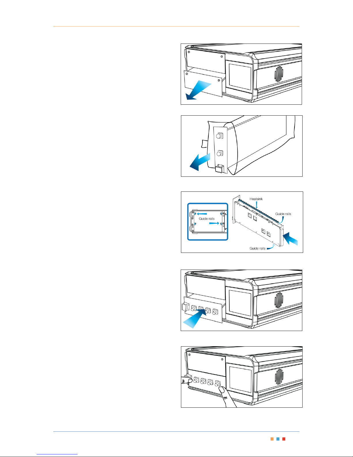
3. Slide the blanking module out to remove it and
store the blanking module near the
MTPmini for future use.
Figure 5 - Removing Blanking Module
Remove the Blade from packaging
4. Unpack the Blade module from the antistatic
packaging, making sure to store the packaging
near the MTPmini so it is available to safely store
any Blade that may be removed in the future.
Figure 6 - Remove and store Antistatic Packaging
Insert the Blade securing into place
5. Slide the Blade into the available slot using the
guide rails.
6. Once the Blade reaches the connector at the end
of the slot, press your thumbs on the release
latch as shown in Figure 9 to make sure the Blade
seats correctly.
Figure 8 - Installing the Blade Module
Figure 9 - Press the Blade Module to seat it into the
Connector
Figure 7 - MTPmini and Blade Guide Rails
Page 13
Modular Test Platform | MTPmini
Coherent Solutions | MTPmini (V1) 9
7. Once the Blade is installed, fasten the screw in
the release latch to lock the Blade into place.
Figure 10 - Fasten screw in Release Latch
Power on the MTPmini
8. Power on the MTPmini by pressing the Power
On/Off switch. The Fans will activate to verify
that the instrument is powered on.
Figure 11 - Powering On the MTPmini
IMPORTANT
After powering on the MTPmini, please wait at least 1 minutes before attempting
to communicate with the instrument. This will allow the MTPmini enough time to
finish boot procedures and initialize the communication server.
The new Blade is now ready for use.
9. Use your preferred method of communicating
with the MTPmini to use the newly installed
Blade.
Figure 12 - TIM software
Page 14
Modular Test Platform | MTPmini
Coherent Solutions | MTPmini (V1) 10
7 Removing a Blade Expansion Module
WARNING
DO NOT attempt to remove or adjust any component of the MTPmini while the
power is on. Make sure you follow the correct procedures below and power down
the MTPmini first.
CAUTION
The Blade is sensitive to ESD. Please be sure to wear a grounded wrist strap at
all times when handling the Blade module to prevent such damage.
Take care not to handle the connector on the Blade module once they are
exposed as this may leave corrosive residue which can damage the connector.
IMPORTANT
A Blanking module will be required to replace the removed Blade module.
Please make sure you have a blanking module available. The specifications of
the Blade are only valid when all empty slots have blanking modules.
You will need antistatic packaging to store the Blade upon removal at the
appropriate step in the following installation procedures. Please make sure
this packaging is immediately available before continuing with the following
procedure.
Note: You will need a Phillips and Slot screwdriver to both unfasten the Blade module and secure the blanking
module in place.
Acquire storage electrostatic packaging and blanking module
1. In preparation for removal of the Blade module, locate and retrieve the antistatic packaging the Blade was
supplied in. This should have been stored near the MTPmini when the Blade was installed.
2. Also you will require a blanking module to install once the Blade has been removed.
IMPORTANT
Do not continue unless you have the blanking module and appropriate storage
packaging for the removed Blade. If the Blade is not stored correctly it may be
affected by ESD. The specifications of the Blade are only valid when all slots have
blanking modules.
Page 15
Modular Test Platform | MTPmini
Coherent Solutions | MTPmini (V1) 11
Power down the MTPmini
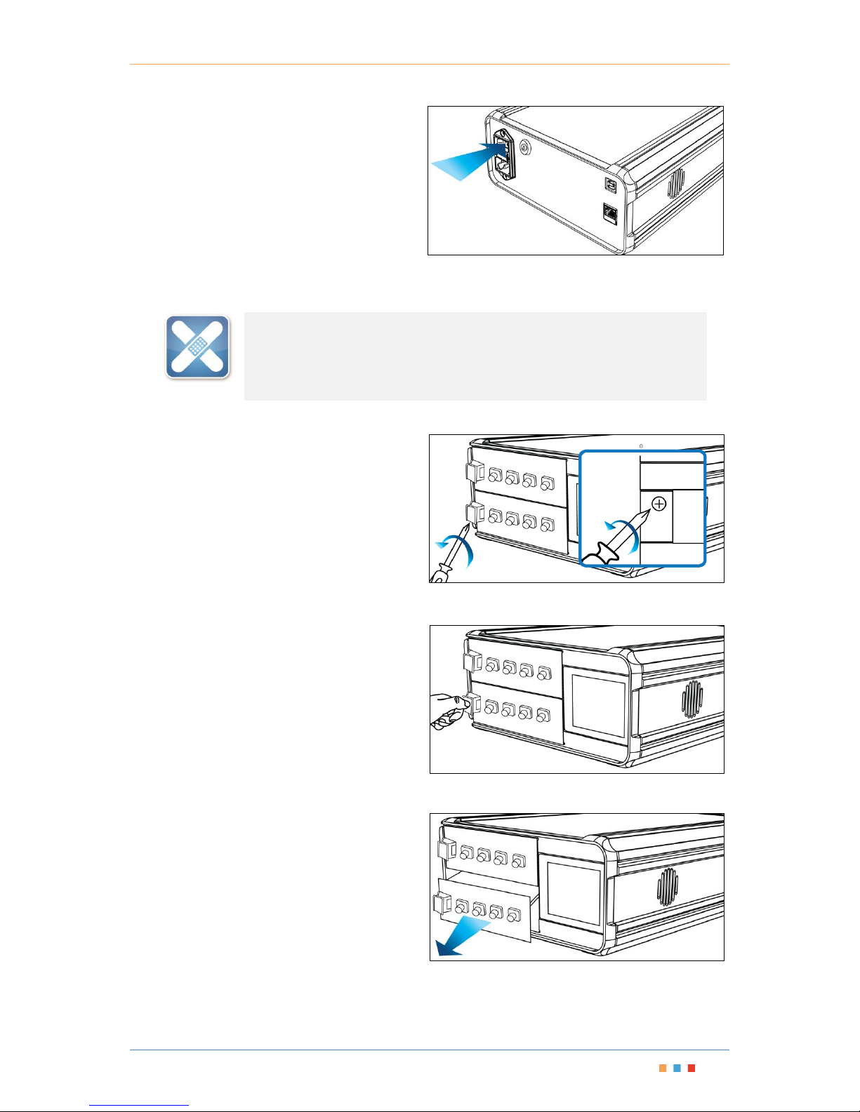
3. Press the Power On/Off switch to
power off the instrument.
Figure 13 - Turn Off Power
WARNING
Take care when handling the Blade as during operation the Blade module may be
very hot.
Remove the Blade
4. To remove the desired Blade module, loosen
the screw underneath the release latch. Do not
try to remove the screw completely as they are
designed to stay inside the release latch.
Figure 14 - Unfasten screw under Release Latch
5. Press downward on the release latch to unseat
the Blade module from the back connector as
shown in Figure 15.
Figure 15 - Press down on the Release Latch
6. Slide the Blade module out to remove.
Figure 16 - Slide out the Blade Module
Page 16
Modular Test Platform | MTPmini
Coherent Solutions | MTPmini (V1) 12
Package the Blade for storage
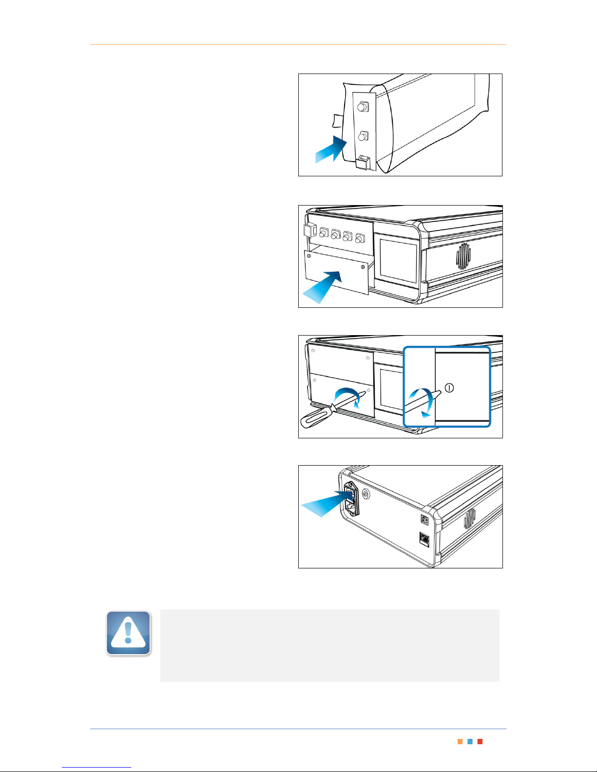
7. Once removed, put the Blade module into the
antistatic packaging for storage. This will
ensure the Blade is not subject to ESD.
Figure 17 - Storing the Blade Module
8. Slide the blanking module into the empty slot
using the guide rails.
Figure 18 - Installing the Blanking Module
9. Once the blanking module is fully inserted,
fasten the captive screws on the top and
bottom of the blanking module to secure it into
place.
Figure 19 - Fasten screws under Release Latch
Power on the MTPmini
10. Power on the MTPmini by pressing the Power
On/Off switch. The Fans will activate to verify
that the instrument is powered on.
Figure 20 - Power on the MTPmini
IMPORTANT
After powering on the MTPmini, please wait at least 2 minutes before attempting to
communicate with the instrument. This will allow the MTPmini enough time to finish
boot procedures and initialize the communication server.
Page 17
Modular Test Platform | MTPmini
Coherent Solutions | MTPmini (V1) 13
8 Operating the MTPmini
8.1 Output Enable/Disable
The Laser Control key switch is used to lock or unlock all the optical sources within the MTPmini for safety
purposes. While this key switch is in the Laser Disabled position (Vertical), it will override any user or software
control by disabling the output of all optical sources installed in the unit. The output state of all the optical
sources cannot be changed. While this key switch is in the Laser Control On position (Horizontal) the users or
software is able to control the output state of all optical sources.
Note: When the Laser Interlock is switched ON, the output state of the lasers before the key was switched OFF
is not restored. The laser states will have to be re-enabled in the software.
8.2 Powering On/Off the MTPmini
To power on the MTPmini simply press the Power On/Off switch; the switch will become illuminated to verify
the instrument is powered on.
IMPORTANT
After powering on the MTPmini, please wait at least 2 minutes before attempting
to communicate with the instrument. This will allow the MTPmini enough time to
finish boot procedures and initialize the communication server.
To power off the MTPmini press the Power On/Off switch. The switch will no longer be illuminated to show the
instrument is off.
8.3 Local Control Touch Screen Graphical User Interface
The MTPmini has a touch screen graphical user interface (referred to as the Display) which provides local
access to the web server application.
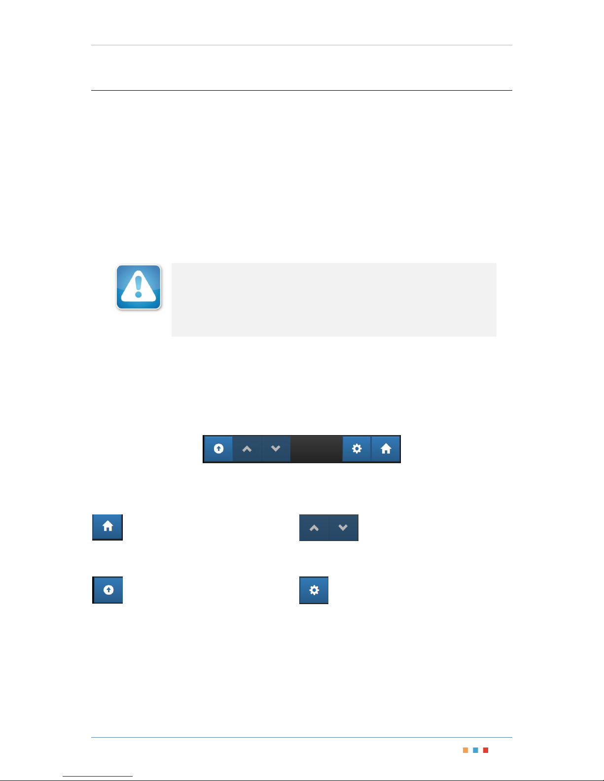
Figure 21 – Display navigation bar
8.3.1 Navigating within the touchscreen LCD
Navigation of the system menu is achieved by using the touch screen buttons on the navigation bar.
- The ‘Home’ button will navigate you back
to the first screen of the Display showing the blades
within the MTPmini.
- The first button is used to take a step
‘back’ one level in the menu system. So this will
return you to the previous menu page.
- The ‘up’ and ‘down’ arrows are used
to scroll the selections of the menu when there are
more options than can be displayed.
- The ‘Settings’ button will take you to the all
the configuration menus of the MTPmini (see below).
Page 18
Modular Test Platform | MTPmini
Coherent Solutions | MTPmini (V1) 14
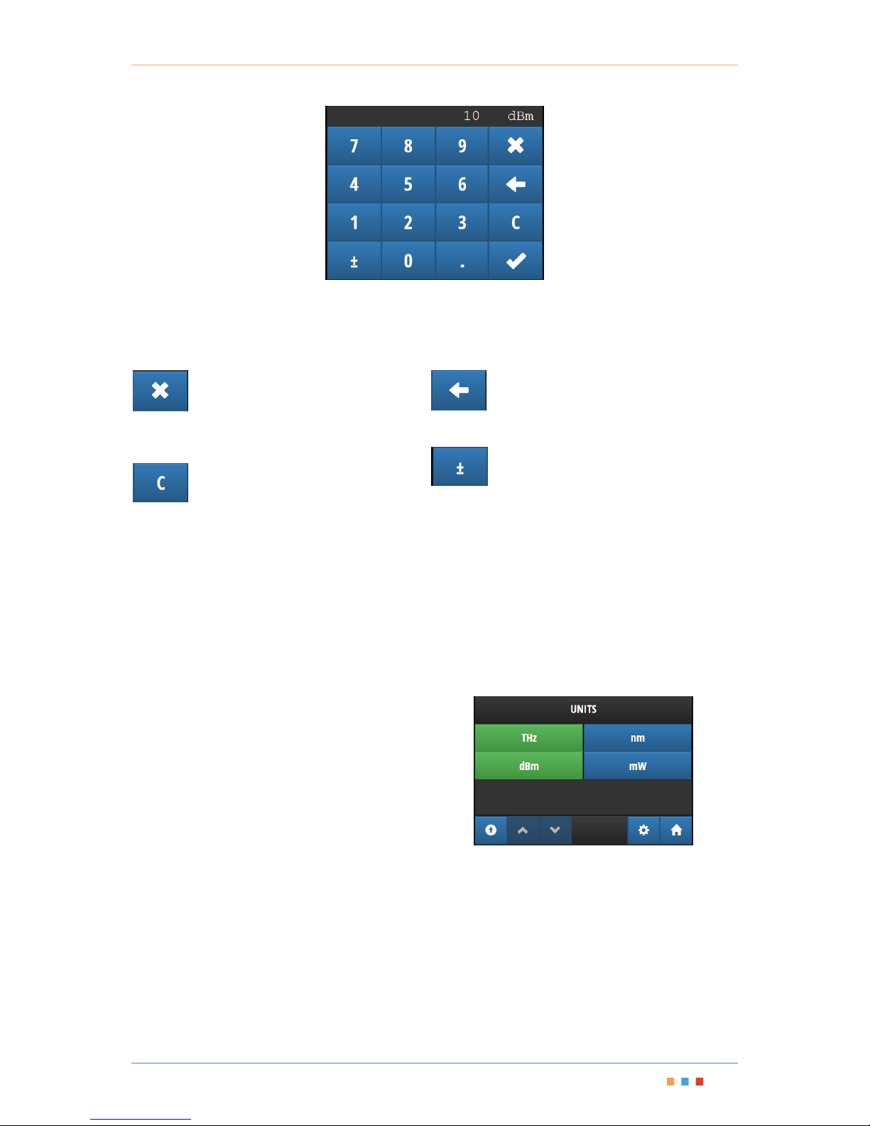
Figure 22 – Touch Screen Graphical User Interface
8.3.2 Changing Numerical Values
To change numerical values, pressing the value on the Display will bring up a numerical pad for data entry. The
value (and units) appears at the top of the Display.
- The ‘Cancel’ button will exit the
numerical pad and return to the previous screen
without changing any values.
- The ‘Clear’ button is used to completely
clear all data from the input field
The ‘Erase’ button is used to delete the last
(right most) digit from the input field.
- The ‘Sign’ button is used to set the sign of
the input value.
Numerical values may also be changed by clicking on the '+' and '-' or the '<' and '>' buttons if they appear next
to a value.
The '+' and '-' buttons will use the current step size and unit to determine how much to increase or decrease
the value, but will not allow the value to exceed the minimum or maximum value
The '<' and '>' buttons will increase or decrease from a list of predefined values, such as wavelength values.
These buttons will also not be able to exceed the highest or lowest of the predefined values
8.3.3 Changing Numerical Units
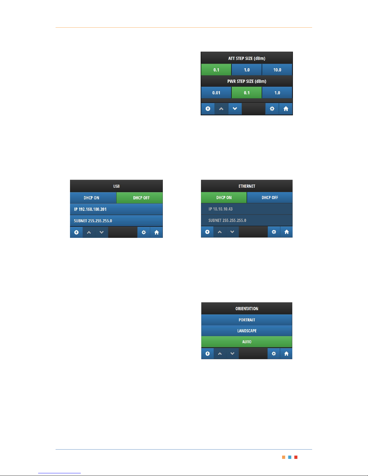
To change between numerical units, navigate to the
‘Settings’ menu and select ‘Units’. Within this menu
you can change between THz or nm (for frequency
and wavelength) and dBm or mW (for optical power
output)
Figure 23 - Units selection menu
Page 19
Modular Test Platform | MTPmini
Coherent Solutions | MTPmini (V1) 15
8.3.4 Changing Step Size
To change the step size for a laser source, navigate
to the ‘Settings’ menu and select ‘Step Size’. There
are individual options for Power, Frequency and
Attenuation. The frequency option will be replaced
by a wavelength option if the units have been
changed to 'nm' on the unit selection screen.
Figure 24 - Step Size selection menu
8.3.5 Viewing or Changing the Network Settings
To view the current network configuration of the instrument, navigate to the 'SETTINGS' menu and select
'ETHERNET'.
Once selected the configuration of the networking interface including static IP i.e. ‘DHCP ON’ or 'DHCP OFF'
buttons, the IP address i.e. 'IP' row, subnet mask i.e. 'SUBNET' row will be displayed.
Network settings may only be changed via the USB interface.
Figure 25 - USB network configuration
Figure 26 - Ethernet network configuration
To allow your network to assign an IP address to the device, select the 'DHCP ON' button. This will disable 'IP'
and 'SUBNET' controls and an IP address will be automatically assigned to the device.
If 'DHCP OFF' is selected, the 'IP' and 'SUBNET' options will be enabled, clicking on either of them will show the
numeric input control so that an IP address can be entered.
8.3.6 Orientation Settings
The MTPmini can be used either horizontally or vertically,
and the device will change the interface orientation
automatically to match if it is set to "AUTO" mode.
If the device needs to be locked to a specific mode
regardless of how the device is oriented, choose
"PORTRAIT" or "LANDSCAPE" modes as required.
"PORTRAIT" mode will show the user interface as if it
were placed vertically, while "LANDSCAPE" mode will
show the user interface as if it were placed horizontally.
Figure 27 – Orientation Settings menu
Page 20

Modular Test Platform | MTPmini
Coherent Solutions | MTPmini (V1) 16
8.4 Remote Operation of the MTPmini
Management and operation of the MTPmini is all performed remotely (TCP/IP over Ethernet or USB) from a
client PC, either using the provided Test Instrument Manager software or VISA programming environments.
8.4.1 Web Graphical User Interface
Once the Ethernet (Or USB) connection to the instrument is established, you can operate the MTPmini using
your favourite web browser. Simply enter the IP (192.168.100.201 for example if on USB) into the address field
and you will be taken to the Display menu.
8.4.2 Test Instrument Manager Software
The Test Instrument Manager software provides an easy to use graphical interface for configuration and
management of the installed Blade modules. See the corresponding manual for the Blade for details of the use
and functionality of this software.
8.4.3 Programming using Virtual Instrument Software Architecture (VISA)
Programming of the MTPmini can be achieved using programming environments that support VISA such as
MATLAB. Please see the corresponding manual for the Blade for detailed information.
Page 21

Modular Test Platform | MTPmini
Coherent Solutions | MTPmini (V1) 17
9 Installing the Software
IMPORTANT
Make sure the client PC is connected to the same network as the MTPmini and the
MTPmini is also powered on before proceeding with software installation.
9.1
Client System Minimum Requirements
Operating System
Windows 7 or later
Minimum Screen Resolution
800x600
Free Hard Disk Space
1GB
Communication Port
USB 2.0 (Ethernet and USB 2.0 recommended)
9.2 Test Instrument Manager Software Installation
Begin the installation by running the ‘CSTIMSetup_[version].exe’ file located on the supplied media. This will
start the installation of the Test Instrument Manager software package.
1. When the installation begins, you will see the Welcome screen. Click on Next to begin the installation.
2. Please read the license agreement. If you choose to accept the agreement, click on the “I accept the terms
of the License Agreement” check box and then click "Install". If you do not wish to accept the terms of the
agreement, click on "Cancel" to terminate the software installation.
3. Once the license agreement has been accepted the installation will begin and the file progress will be
displayed throughout the installation.
4. When the installation has completed you can click on "Finish" with the check box ticked (by default) to
immediately start the Test Instrument Manager software.
5. The installer will also place a Test Instrument Manager application shortcut on your desktop.
6. Refer to the Blades’ manual for details of the use and functionality of this software.
Page 22

Modular Test Platform | MTPmini
Coherent Solutions | MTPmini (V1) 18
10 Maintenance
To help ensure long, trouble-free operation:
Keep the unit free of dust.
Always use blanking modules in slots that do not have a working Blade module.
Clean the unit casing and front panel with a cloth slightly dampened with water.
Store unit at room temperature in a clean and dry area. Keep the unit out of direct sunlight.
Avoid high humidity or significant temperature fluctuations.
Avoid unnecessary shocks and vibrations.
If any liquids are spilled on or into the unit, turn off the power immediately, disconnect from any
external power source, remove the batteries and let the unit dry completely.
WARNING
The use of controls, adjustments and procedures other than those specified herein
may result in exposure to hazardous situations or impair the protection provided
by this unit.
Page 23
Modular Test Platform | MTPmini
Coherent Solutions | MTPmini (V1) 19
NOTICE
通告
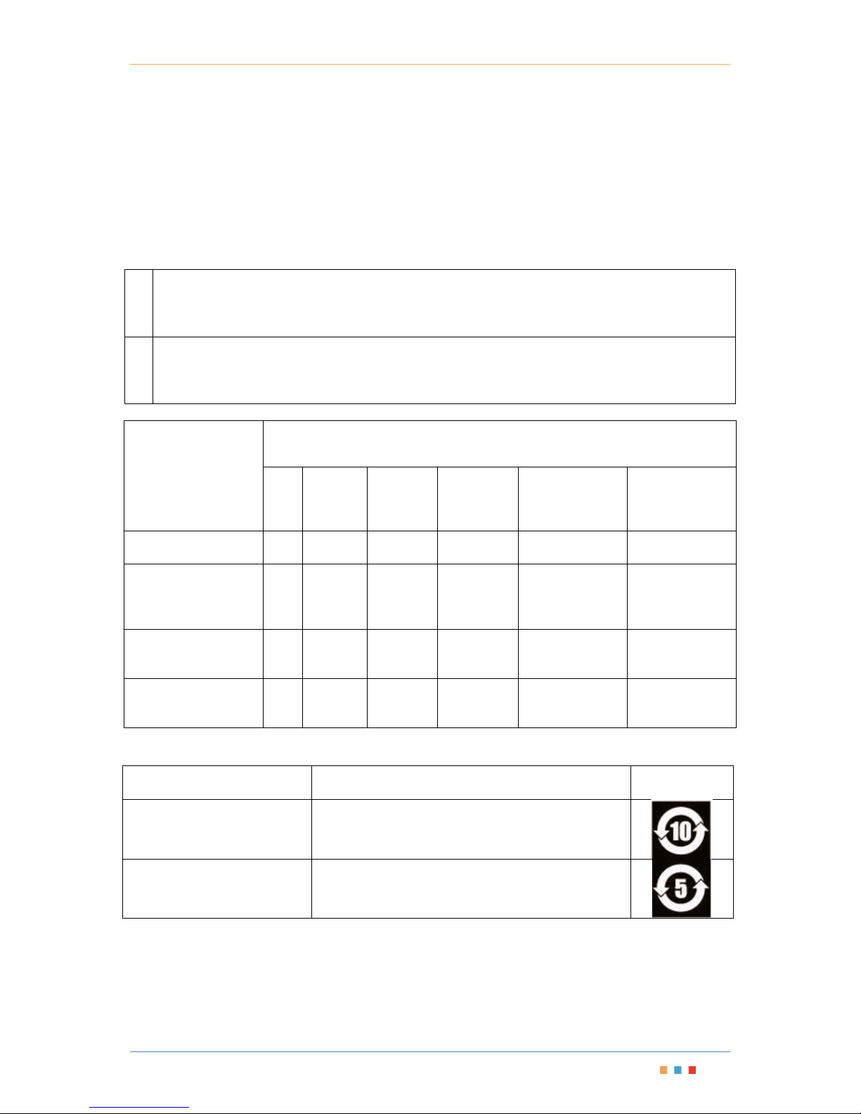
CHINESE REGULATION ON RESTRICTION OF HAZARDOUS SUBSTANCES
中国关于危害物质限制的规定
NAMES AND CONTENTS OF THE TOXIC OR HAZARDOUS SUBSTANCES OR ELEMENTS CONTAINED IN THIS
COHERENT SOLUTIONS PRODUCT
包含在本 COHERENT SOLUTIONS 产品中的有毒有害物质或元素的名称和含量
O
Indicates that this toxic or hazardous substance contained in all of the homogeneous materials for this
part is below the limit requirement in SJ/T11363-2006
表示该有毒有害物质在该部件所有均质材料中的含量均在 SJ/T11363-2006 标准规定的限量要求以
下。
X
Indicates that this toxic or hazardous substance contained in at least one of the homogeneous materials
used for this part is above the limit requirement in SJ/T11363-2006
表示该有毒有害物质至少在该部件的某一均质材料中的含量超出 SJ/T11363-2006 标准规定的限量
要求。
Part Name
部件名称
Toxic or hazardous Substances and Elements
有毒有害物质和元素
Lead
铅
(Pb)
Mercury
汞
(Hg)
Cadmium
镉
(Cd)
Hexavalent
Chromium
六价铬
(Cr VI)
Polybrominated
biphenyls
多溴联苯
(PBB)
Polybrominated
diphenyl ethers
多溴二苯醚
(PBDE)
Enclosure
外壳
O O O O O
O
Electronic and
electrical sub-
assembly
电子和电子组件
X O X O X
X
Optical
sub-assemblya
光学组件
a
X O O O O
O
Mechanical
sub-assemblya
机械组件
a
O O O O O
O
MARKING REQUIREMENTS 标注要求
Product
产品
Environmental protection use period (years)
环境保护使用期限(年)
Logo
标志
This Coherent Solutions product
本 Coherent Solutions 产品
10
Battery
a
电池
a
5
a. If applicable.
如果适用
Page 24

Modular Test Platform | MTPmini
Coherent Solutions | MTPmini (V1) 20
11 Technical Support
11.1 Contacting the Technical Support Group
To obtain after-sales service or technical support for this product, contact Coherent Solutions. The Technical
Support Group is available to take your calls from Monday to Friday, 9:00 a.m. to 5:00 p.m. (New Zealand
Time).
Technical Support Group
Tel.: +64 9 478 4849
Fax: +64 9 478 4851
[email protected]
To accelerate the process, please have information such as the name and the serial number (see the product
identification label), as well as a description of your problem, close at hand.
You may also be requested to provide software and module version numbers. This information, as well as
technical support contact information, can be found in the ‘About’ window.
11.2 Transportation
Maintain a temperature range within specifications when transporting the unit. Transportation damage can
occur from improper handling. The following steps are recommended to minimize the possibility of damage:
Pack the unit in its original packing material when shipping.
Avoid high humidity or large temperature fluctuations.
Keep the unit out of direct sunlight.
Avoid unnecessary shocks and vibrations.
IMPORTANT
Keep this manual close at hand as it contains important details about your product.
Page 25

Modular Test Platform | MTPmini
Coherent Solutions | MTPmini (V1) 21
12 Warranty
12.1 General Information
Coherent Solutions Ltd. (Coherent Solutions) warrants this equipment against defects in material and
workmanship for a period of three years from the date of original shipment. Coherent Solutions also warrants
that this equipment will meet applicable specifications under normal use.
During the warranty period, Coherent Solutions will, at its discretion, repair, replace, or issue credit for any
defective product, as well as verify and adjust the product free of charge should the equipment need to be
repaired or if the original calibration is erroneous. If the equipment is sent back for verification of calibration
during the warranty period and found to meet all published specifications, Coherent Solutions will charge
standard calibration fees.
IMPORTANT
The warranty can become null and void if:
The unit has been tampered with, repaired, or worked upon by unauthorized
individuals or non-Coherent Solutions personnel.
The warranty sticker has been removed.
The case screws, other than those specified in this guide, have been removed.
The case has been opened, other than as explained in this guide.
The unit serial number has been altered, erased, or removed.
The unit has been misused, neglected, or damaged by accident.
THIS WARRANTY IS IN LIEU OF ALL OTHER WARRANTIES EXPRESSED, IMPLIED, OR STATUTORY, INCLUDING,
BUT NOT LIMITED TO, THE IMPLIED WARRANTIES OF MERCHANTABILITY AND FITNESS FOR A PARTICULAR
PURPOSE. IN NO EVENT SHALL COHERENT SOLUTIONS BE LIABLE FOR SPECIAL, INCIDENTAL, OR
CONSEQUENTIAL DAMAGES.
12.2 Liability
Coherent Solutions shall not be liable for damages resulting from the use of the product, nor shall be
responsible for any failure in the performance of other items to which the product is connected or the
operation of any system of which the product may be a part.
Coherent Solutions shall not be liable for damages resulting from improper usage, transportation or
unauthorized modification of the product, its accompanying accessories and software.
12.3 Exclusions
Coherent Solutions reserves the right to make changes in the design or construction of any of its products at
any time without incurring obligation to make any changes whatsoever on units purchased. Accessories,
including but not limited to fuses, pilot lamps, batteries and universal interfaces (EUI) used with Coherent
Solutions products are not covered by this warranty.
This warranty excludes failure resulting from: improper use or installation, normal wear and tear, accident,
abuse, neglect, fire, water, lightning or other acts of nature, causes external to the product or other factors
beyond the control of Coherent Solutions.
Page 26

Modular Test Platform | MTPmini
Coherent Solutions | MTPmini (V1) 22
IMPORTANT
Coherent Solutions will charge a fee for replacing optical connectors that were
damaged due to misuse or bad cleaning.
12.4 Certification
Coherent Solutions certifies that this equipment met its published specifications at the time of shipment from
the factory.
12.5 Service and Repairs
Coherent Solutions commits to providing product service and repair for five years following the date of
purchase.
To send any equipment for service or repair:
1. Contact Coherent Solutions, contact details are on the back cover. Support personnel will determine if the
equipment requires service, repair, or calibration.
2. If possible, back up your data before sending the unit for repair.
3. Pack the equipment in its original shipping material. Be sure to supply a statement or report fully detailing
the defect and the conditions under which it was observed.
4. Return the equipment, prepaid, to Coherent Solutions.
Note: A test setup fee will apply to any returned unit that, after test, is found to meet the applicable
specifications.
After repair, the equipment will be returned with a repair report. If the equipment is not under warranty, you
will be invoiced for the cost appearing on this report. Coherent Solutions will pay return-to-customer shipping
costs for equipment under warranty. Shipping insurance is at your expense.
Page 27

V1
 Loading...