


PXIe Platform Photonic Doppler Velocimetry | DopplerPXIe
i
Copyright © 2018 Coherent Solutions Ltd. All rights reserved. No part of this publication may be reproduced,
stored in a retrieval system or transmitted in any form, be it electronically, mechanically, or by any other
means such as photocopying, recording or otherwise, without the prior written permission of Coherent
Solutions Ltd. (Coherent Solutions).
Information provided by Coherent Solutions is believed to be accurate and reliable.
However, no responsibility is assumed by Coherent Solutions for its use nor for any infringements of patents or
other rights of third parties that may result from its use. No license is granted by implication or otherwise
under any patent rights of Coherent Solutions.
The information contained in this publication is subject to change without notice.
Trademarks
Coherent Solutions’ trademarks have been identified as such. However, the presence or absence of such
identification does not affect the legal status of any trademark.
Units of Measurement
Units of measurement in this publication conform to SI standards and practices.
Version Number: V1.1

PXIe Platform Photonic Doppler Velocimetry | DopplerPXIe
ii
Contents
1 Conventions ............................................................................................................ 1
2 Safety Information ................................................................................................... 2
3 Introducing the DopplerPXIe – Modular Variable Optical Attenuator........................ 3
3.1 Overview & Features ............................................................................................................................. 3
4 Connecting Optical Output ....................................................................................... 5
4.1 Cleaning and Connecting Optical Fibers ................................................................................................ 5
5 CSL Server Installation ............................................................................................. 6
5.1 CSL Driver Installation ........................................................................................................................... 6
5.2 CSL Server Installation ......................................................................................................................... 10
6 Handling the DopplerPXIe Module ......................................................................... 18
6.1 DopplerPXIe Module Installation ........................................................................................................ 18
6.2 DopplerPXIe Module Uninstallation.................................................................................................... 20
7 Programming Guide ............................................................................................... 21
7.1 Programming Conventions .................................................................................................................. 21
7.2 Specific Command Summary .............................................................................................................. 22
7.3 Specific Command Descriptions .......................................................................................................... 22
7.3.1 Slot Commands ............................................................................................................................... 22
7.3.2 Configuration Commands ............................................................................................................... 23
8 Maintenance ......................................................................................................... 28
9 Technical Support .................................................................................................. 30
9.1 Contacting the Technical Support Group ............................................................................................ 30
9.2 Transportation .................................................................................................................................... 30
10 Warranty ............................................................................................................... 31
10.1 General Information ............................................................................................................................ 31
10.2 Liability ................................................................................................................................................ 31
10.3 Exclusions ............................................................................................................................................ 31
10.4 Certification ......................................................................................................................................... 32
10.5 Service and Repairs ............................................................................................................................. 32
PXIe Platform Photonic Doppler Velocimetry | DopplerPXIe
Coherent Solutions | 1
1 Conventions
Before using the instrument described in this manual, you should understand the following
conventions:
WARNING
Indicates a potentially hazardous situation which, if not avoided, could
result in death or serious injury. Do not proceed unless you understand and
meet the required conditions.
CAUTION
Indicates a potentially hazardous situation which, if not avoided, may result
in minor or moderate injury. Do not proceed unless you understand and
meet the required conditions.
CAUTION
Indicates a potentially hazardous situation which, if not avoided, may result
in component damage. Do not proceed unless you understand and meet
the required conditions.
IMPORTANT
Refers to information about this product you should not overlook.
PXIe Platform Photonic Doppler Velocimetry | DopplerPXIe
Coherent Solutions | 2
2 Safety Information
WARNING
Do not install or terminate fibers while a light source is active. Care
must be taken to ensure that the instrument has been turned OFF
before inspecting the end face(s) of the instrument, or any optical
patch cords connected to this instrument. Never look directly into a live
fiber and ensure that your eyes are protected at all times.
The use of controls, adjustments and procedures other than those
specified herein may result in exposure to hazardous situations or
impair the protection provided by this unit.
CAUTION
The DopplerPXIe modules are sensitive to electrostatic discharge (ESD).
Please be sure to store the modules that are not installed in protective
electrostatic packaging.
IMPORTANT
For electromagnetic compatibility, this instrument is a Class A product.
It is intended for use in an industrial environment. There may be
potential difficulties in ensuring electromagnetic compatibility in other
environments, due to conducted as well as radiated disturbances.
When you see the symbol on your unit, make sure that you refer
to the instructions provided in your user documentation. Ensure that
you understand and meet the required conditions before using your
product.
PXIe Platform Photonic Doppler Velocimetry | DopplerPXIe
Coherent Solutions | 3
3 Introducing the DopplerPXIe – Modular Photonic Doppler Velocimetry
The DopplerPXIe combines the critical optical components for PDV measurements in a single slot
PXIe module to enable compact, inexpensive and robust Photonic Doppler
velocimetry measurement.
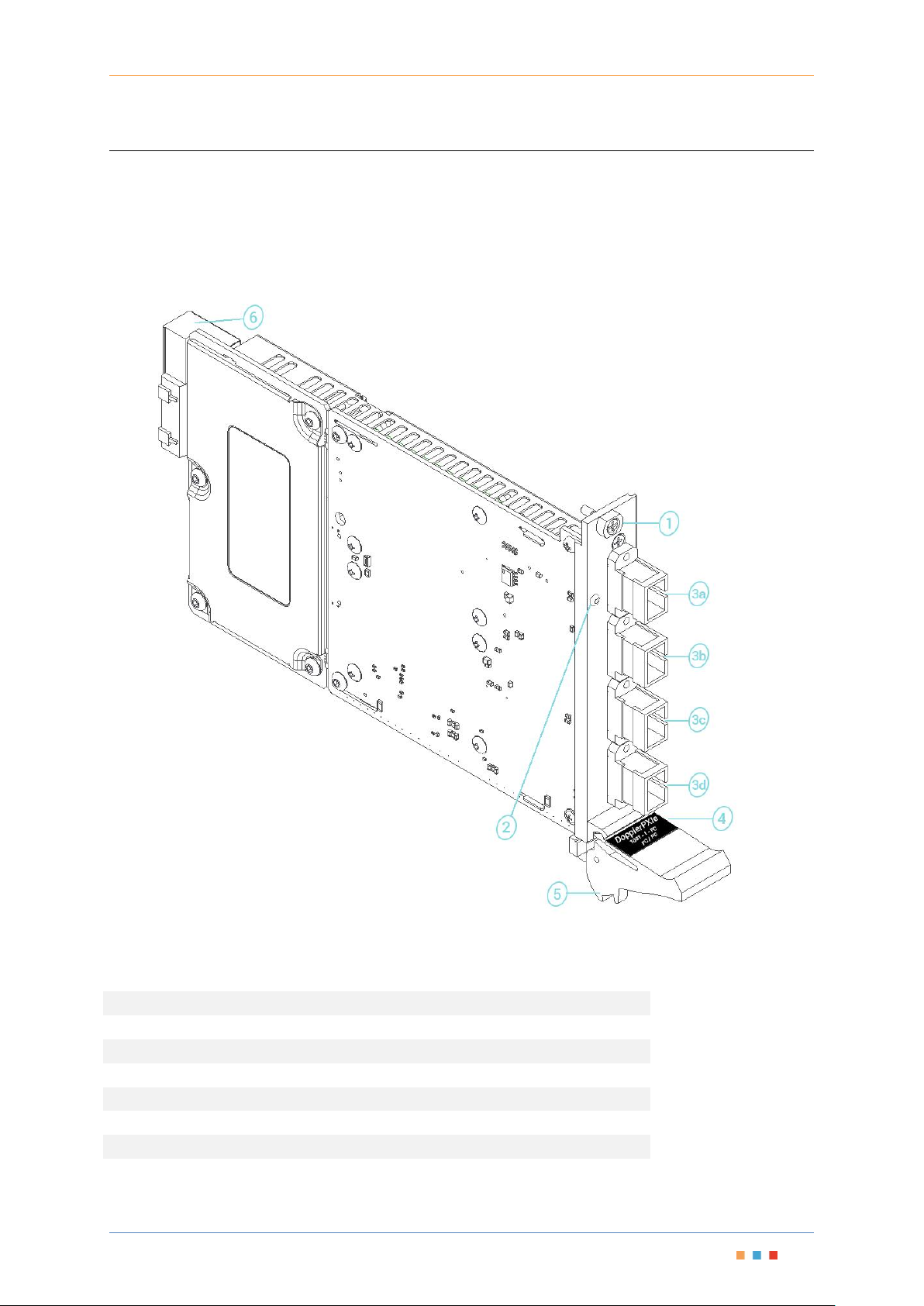
3.1 Overview & Features
1
Fastening screw
2
Status LEDs
3a
Optical Probe Input/Output port
3b
Optical Target Input port
3c
Optical Reference Input port
3d
Optical Signal Output port
4
Optical Connector Information
5
Fastening clip
6
PXIe Headers

PXIe Platform Photonic Doppler Velocimetry | DopplerPXIe
Coherent Solutions | 4
3.2 Functional Diagram
Two lasers are connected to the Target Input port and Reference Input ports respectively. The
Target laser passes through a circulator and exits the Probe port. This beam will interact with the
DUT (target) and be reflected into the Probe Port.
The input into the probe port will pass through the circulator and be directed to the optical
attenuator and inline power meter.
The Reference laser passes though an optical attenuator and inline power meter.
The Reference laser and the Probe input are coupled to the Output port through a 10%:90% coupler
respectively.
Through this configuration, independent control of the Probe power and the Reference power is
achieved. The Power Meter is referenced to the output port, so it takes all internal losses of the
optical coupler into consideration when reporting the optical power of the probe and reference.

PXIe Platform Photonic Doppler Velocimetry | DopplerPXIe
Coherent Solutions | 5
4 Connecting Optical Output
IMPORTANT
To ensure maximum power and to avoid erroneous readings always inspect
fiber ends and make sure that they are clean as explained below before
inserting them into the port. Coherent Solutions is not responsible for
damage or errors caused by bad fiber cleaning or handling.
CAUTION
The type of optical connectors on the DopplerPXIe module can be found
printed on the front plate of the module and in the separate Spec sheet
provided. Joining mismatched connectors will damage the ferrules.
4.1 Cleaning and Connecting Optical Fibers
To connect the fiber-optic cable to the port:
1. Inspect the fiber using a fiber inspection microscope. If the fiber is clean, proceed to connecting
it to the port. If the fiber is dirty, clean it as explained below.
2. Clean the fiber ends as follows:
2a. Gently wipe the fiber end with a lint-free swab dipped in isopropyl alcohol.
2b. Use compressed air to dry completely.
2c. Visually inspect the fiber end to ensure its cleanliness.
3. Carefully align the connector and port to prevent the fiber end from touching the outside of the
port or rubbing against other surfaces. If your connector features a key, ensure that it is fully
fitted into the port’s corresponding notch.
4. Push the connector in so that the fiber-optic cable is firmly in place, thus ensuring adequate
contact. If your connector features a screw sleeve, tighten the connector enough to firmly
maintain the fiber in place. Do not over tighten, as this will damage the fiber and the port.
Note: If your fiber-optic cable is not properly aligned and/or connected, you will notice heavy loss and
reflection.
Coherent Solutions uses good quality connectors in compliance with EIA-455-21A standards.
To keep connectors clean and in good condition, Coherent Solutions strongly recommends
inspecting them with a fiber inspection probe before connecting them. Failure to do so will result in
permanent damage to the connectors and degradation in measurements.
PXIe Platform Photonic Doppler Velocimetry | DopplerPXIe
Coherent Solutions | 6
5 CSL Server Installation
IMPORTANT
The software requires installation on the PXIe Chassis. The CSLServer is
installed as a service to auto start when the chassis is powered on.
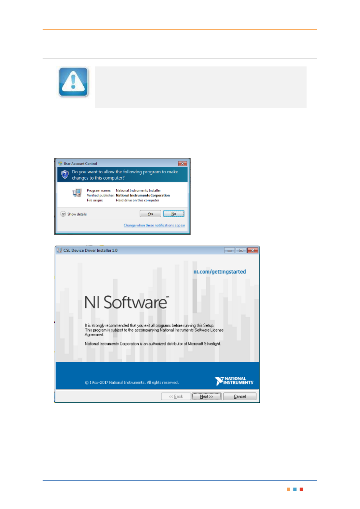
5.1 CSL Driver Installation
Windows 7
1. Locate installer setup.exe in the CSLDriverInstaller folder on the provided media.
2. Allow installation by clicking ‘Yes’ in the User Account Control prompt.
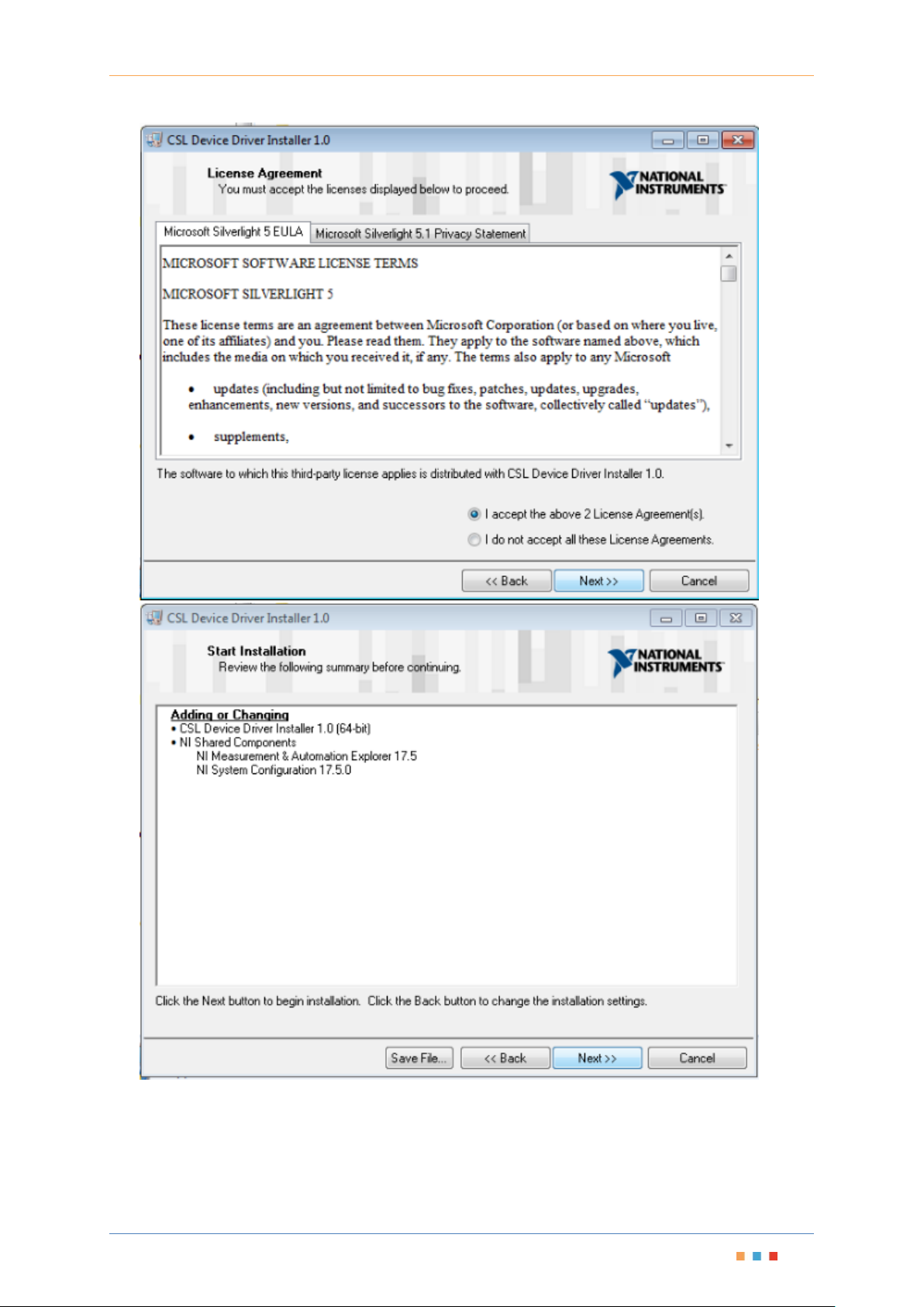
3. Proceed with the NI CSL Driver installation and accept Licence Agreements.
PXIe Platform Photonic Doppler Velocimetry | DopplerPXIe
Coherent Solutions | 7
PXIe Platform Photonic Doppler Velocimetry | DopplerPXIe
Coherent Solutions | 8

PXIe Platform Photonic Doppler Velocimetry | DopplerPXIe
Coherent Solutions | 9
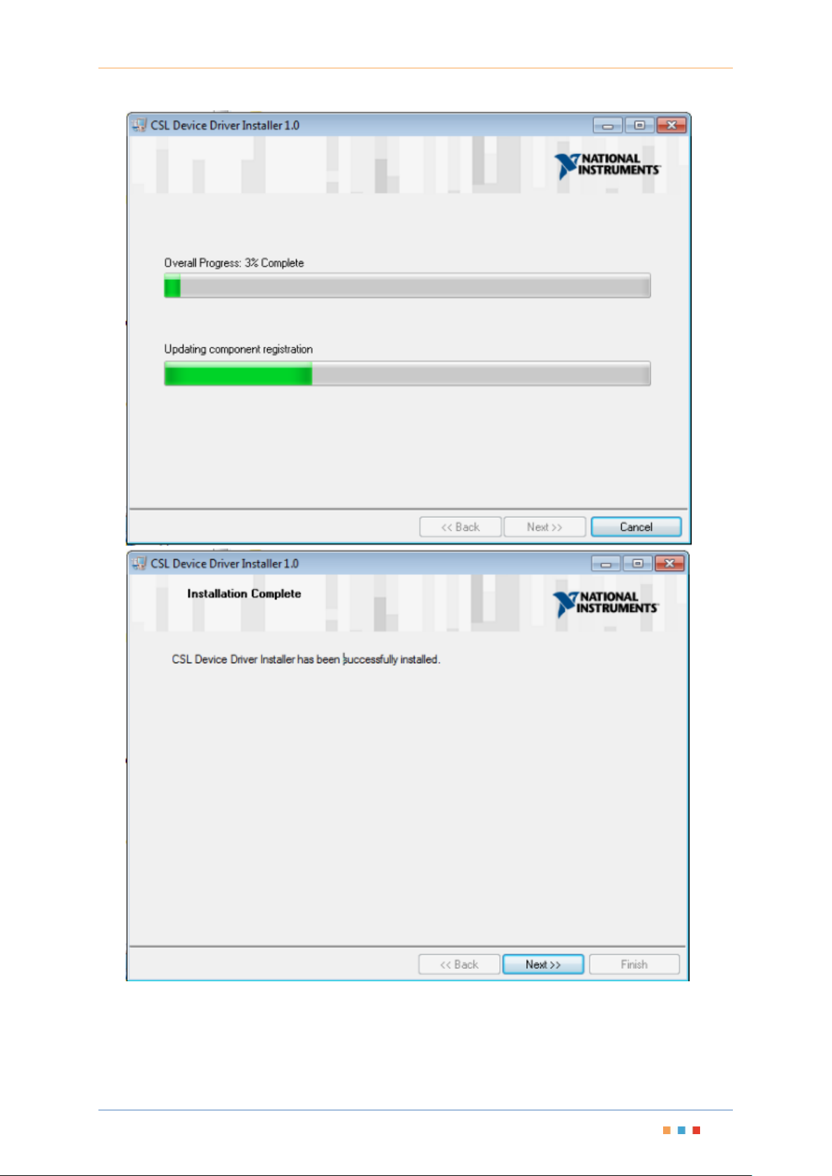
4. Select the ‘Shut Down’ option in the final prompt to install the CSL PXIe Modules into the Chassis.
5. Once the new modules are installed, power back on the Chassis.
The Chassis will now install the new drivers for the installed modules and you are able to install
the CSLServer VXI11 service to the Chassis (see the following section).
The modules will show up in device manager as CSL Devices:

PXIe Platform Photonic Doppler Velocimetry | DopplerPXIe
Coherent Solutions | 10
5.2 CSL Server Installation
Windows 7
1. Locate the CSLServer-x.x.x-win32.exe installer and run this as Administrator (you will be
prompted).
2. Allow installation by clicking ‘Yes’ in the UAC prompt.
3. Proceed with installation accepting Licence Agreement

PXIe Platform Photonic Doppler Velocimetry | DopplerPXIe
Coherent Solutions | 11

PXIe Platform Photonic Doppler Velocimetry | DopplerPXIe
Coherent Solutions | 12
4. Once complete, please reboot the Chassis.

PXIe Platform Photonic Doppler Velocimetry | DopplerPXIe
Coherent Solutions | 13
5.3 CSLWebServer Installation
Windows 7
1. Locate the CSLWebServer-X.XX.XX-x64.exe installer and run this as Administrator (you will
be prompted).
2. Allow installation by clicking ‘Yes’ in the UAC prompt.
3. Proceed with the installation, clicking ‘I accept…’ when the License Agreement prompt pops
up.

PXIe Platform Photonic Doppler Velocimetry | DopplerPXIe
Coherent Solutions | 14
4. Select the type of web server for the setup. If you are already running an IIS service, then
proceed with this option. For all other users we recommend choosing Apache.

PXIe Platform Photonic Doppler Velocimetry | DopplerPXIe
Coherent Solutions | 15
5. Select the install location for the server.

PXIe Platform Photonic Doppler Velocimetry | DopplerPXIe
Coherent Solutions | 16
6. When the Windows Defender Firewall prompt pops up, select ‘Private networks…’ and click
‘Allow access’.
7. Port numbers less than 1024 are reserved. Input an available port number larger than 1024,
and click ‘Next’. If you enter in an invalid or assigned port you will be prompted to re enter a
port number.

PXIe Platform Photonic Doppler Velocimetry | DopplerPXIe
Coherent Solutions | 17
8. Once complete, reboot the Chassis for the installation to complete. Note: After reboot allow
a few minutes for the WebServer to start up and initialise all necessary services.

PXIe Platform Photonic Doppler Velocimetry | DopplerPXIe
Coherent Solutions | 18
6 Handling the DopplerPXIe Module
6.1 DopplerPXIe Module Installation
WARNING
DO NOT attempt to remove or adjust any component of the PXIe chassis
while the power is on. Make sure you follow the correct procedures below
and power down the chassis first.
CAUTION
Do not remove the DopplerPXIe from the antistatic packaging until
instructed during the following installation procedure.
The DopplerPXIe is sensitive to ESD. Please be sure to wear a grounded
wrist strap at all times when handling the DopplerPXIe module to
prevent such damage.
Take care not to handle the connector on the DopplerPXIe module
once they are exposed as this may leave corrosive residue which can
damage the connector.
1. Shutdown the PXIe chassis.
2. If present, remove the current module or
blanking plate in the intended installation
slot.
3. Carefully remove the DopplerPXIe module
from the antistatic packaging bag it was
shipped in.
Retain the bag for storage of the
DopplerPXIe module.
4. Insert the DopplerPXIe module into the
desired slot.
Align the top and bottom lip of the
DopplerPXIe module with the chassis guide
rails. With a firm grip push the module into
the chassis.

PXIe Platform Photonic Doppler Velocimetry | DopplerPXIe
Coherent Solutions | 19
5. Push the module into the chassis until a
resistance is felt.
This is to confirm the header pins on the
back of the module are properly connected
to the chassis.
6. Secure the module into the chassis by
pulling up on the black locking clip.
A click should be heard when the locking
clip is properly engaged into the front
chassis rail.
Secure the fastening screw with a
screwdriver.
7. Perform a visual check to ensure no loose
items or tools have been left in the chassis
after installation.
Power on the PXIe chassis.

PXIe Platform Photonic Doppler Velocimetry | DopplerPXIe
Coherent Solutions | 20
6.2 DopplerPXIe Module Uninstallation
IMPORTANT
After powering on the PXIe chassis, please wait at least 2 minutes before
attempting to communicate with the instrument. This will allow the chassis
enough time to finish boot procedures and initialize the communication
server.
1. Shutdown the PXIe chassis.
2. Unfasten the locking clip on the DopplerPXIe
module. Unscrew the fastening screw.
Pull out the module from the chassis while
firmly gripping the front plate edges of the
DopplerPXIe module. DO NOT PULL THE
MODULE OUT BY GRIPPING ANY OF THE
CONNECTORS.
3. Insert the DopplerPXIe module in the
antistatic bag it was shipped in. Store
appropriately.
4. Power on the PXIe chassis.

PXIe Platform Photonic Doppler Velocimetry | DopplerPXIe
Coherent Solutions | 21
7 Programming Guide
Introduction
Remote communication with the CSLServer is achieved through the Standard Commands for
Programmable Instruments (SCPI). Support for VISA I/O API over TCP/IP is provided by the VXI-11
compliant CSLServer. With VISA communication drivers installed on the client, the implementation
of VISA programming within environments such as MATLAB becomes available. This guide provides
general information on the commands available to communicate with the CSLServer remotely using
the VISA I/O.
7.1 Programming Conventions
This section details the programming and measurement conventions to follow while executing the
commands for the CSLServer.
Table 1 - Valid Units and Data Formats
Argument
Data Format
<wsp>
Specifies whitespace character (0116 – 0916, 0B16 – 2016).
<value>
Is numerical data, an integer, a decimal, exponential (10e-9 or 5.8e6) or
string
[VALUE1|VALUE2]
This is a parameter choice. The ‘|’ separates the unique parameters
available, only one of the choices can be used.
In the example you can use the input parameter [VALUE1] or [VALUE2]
not both.
Some commands may have more than two choices available.
This parameter can be omitted where the command has a default defined
in the command description.
Index Addressing of Modules (slot, source) and VOA’s (channel)
When executing commands, it is almost always necessary to provide the index of a specific
DopplerPXIe module or an index of a specific attenuator.
For the commands that require index values:
[n]: is the slot (or source) index of the specific blade module, this is an integer, <1 to 18>
[m]: is the channel index of a specific attenuator, this is an integer, <1, 2 >.
Message Queues
Information is exchanged in the form of messages. These messages are held in input and output
queues.
The output queue stores responses to query commands. The CSLServer transmits any data in the
output queue when a read request is received. Unless explicitly specified otherwise in the command
description, all output response data is transmitted in ASCII format.

PXIe Platform Photonic Doppler Velocimetry | DopplerPXIe
Coherent Solutions | 22
7.2 Specific Command Summary
Slot commands
Description
:SLOT[n]
:OPC?
:OPTions?
:IDN?
-Query the status of the Operation Complete bit
-Query the modules installed on the slot
-Query the Identifier for the slot; returns the manufacturer,
part number, serial number, hardware and firmware
versions
Configuration commands
Description
:CONTrol[n]: CHANnel[m]
:MODE/?
:INPut[n]:CHANnel[m]
:WAVelength/?
:AMODE/?
:ATTenuation/?
:OFFSet/?
:OUTPut[n]
:CHANnel[m]
:POWer/?
:AVERagingtime/?
:NULLing
:OFFSet/?
:TRACE[m]?
:CoMPlete?
:PoinTS/?
:RATE/?
:TRIGger
-Set or query the control mode
-Set or query the optical wavelength configuration
-Set or query the attenuation mode
-Set or query the attenuation
-Set or query the attenuation mode offset
-Set or query the constant power output
-Set or query the output power averaging time
-Starts dark power nulling
-Set or query the output power offset
-Query the Trace buffer
-Query the status of the Trace Complete bit
-Set or query the number of trace buffer data elements
-Set or query the trace buffer sampling rate
-Triggering of the trace sampling
7.3 Specific Command Descriptions
7.3.1 Slot Commands
Command
:SLOT[n]:OPC?
Syntax
:SLOT[n]:OPC?
Description
Query the status of the Operation Complete bit
Parameters
None
Response
1 is returned if the module is ready to execute a new operation
0 is returned if the module is busy
Example
SLOT1:OPC? -> 1
Command
:SLOT[n]:OPTions?
Syntax
:SLOT[n]:OPTions?
Description
Query the modules installed on the slot
Parameters
None
Response
The response will be a comma separated string of attenuators installed in the DopplerPXIe. If an
attenuator is not installed in a channel, it will not return any identification string.
Example
SLOT1:OPT? -> 1,1,,

PXIe Platform Photonic Doppler Velocimetry | DopplerPXIe
Coherent Solutions | 23
Command
:SLOT[n]:IDN?
Syntax
:SLOT[n]:IDN?
Description
Query the Identifier for the slot; returns the manufacturer, part number, serial number,
hardware and firmware versions
Parameters
None
Response
Comma separated string containing the <manufacturer>, <part number>, <serial
number>,<hardware version><firmware version>
Example
SLOT1:IDN? -> Coherent Solutions,DopplerPXIe-1002-2-FC,CSL998833,0.18
Note: Hardware and firmware versions are combined and not separated by a comma
7.3.2 Configuration Commands
Command
:CONTrol[n]:CHANnel[m]:MODE
Syntax
:CONTrol[n]:CHANnel [m]:MODE<wsp>[ATT|POW|RAW]
Description
Set the control mode
Parameters
ATT: Set to Attenuation control mode
POW: Set to Power control mode
Response
None
Example
CONT1:CHAN1:MODE ATT
Command
:CONTrol[n]:CHANnel [m]:MODE?
Syntax
:CONTrol[n]:CHANnel [m]:MODE?
Description
Query the control mode
Parameters
None
Response
Returns a string (non-abbreviated) of the current control mode for the specified channel
Example
CONT1:CHAN1:MODE? -> ATTENUATION
Command
:INPut[n]:CHANnel [m]:WAVelength
Syntax
:INPut[n]:CHANnel [m]:WAVelength<wsp><value>[NM|M|MM|UM|PM]
Description
Set the optical wavelength configuration
Parameters
<value>: Set to the user wavelength of the channel with the specified units (nm default)
Response
None
Example
INP1:CHAN1:WAV 1310
Command
:INPut[n]:CHANnel [m]:WAVelength?
Syntax
:INPut[n]:CHANnel [m]:WAVelength?<wsp>[MIN|MAX|DEF|SET|ALL]
Description
Query the optical wavelength configuration
Parameters
MIN: Return the minimum programmable wavelength
MAX: Return the maximum programmable wavelength
DEF: Return the default wavelength
SET: Return the set wavelength
ALL: Returns all the above parameters in a comma separated string
Response
Depending on the parameters the response will be a single value or a comma separated string of
values.
Example
INP1:CHAN1:WAV? ALL -> 1271,1550,1550,1310

PXIe Platform Photonic Doppler Velocimetry | DopplerPXIe
Coherent Solutions | 24
Command
:INPut[n]:CHANnel [m]:AMODE
Syntax
:INPut[n]:CHANnel [m]:AMODE<wsp>[ABS|REL|OFFSET]
Description
Set the attenuation mode
Parameters
ABS: Set the attenuation reference to absolute
REL: Set the attenuation reference to relative
OFFSET: Set the attenuation reference to the user offset
Response
None
Example
INP1:CHAN1:AMODE ABS
Command
:INPut[n]:CHANnel [m]:AMODE?
Syntax
:INPut[n]:CHANnel [m]:AMODE?
Description
Query the attenuation mode
Parameters
None
Response
Returns a string (non-abreviated) of the current attenuation mode for the specified channel
Example
INP1:CHAN1:AMODE? -> ABSOLUTE
Command
:INPut[n]:CHANnel [m]:ATTenuation
Syntax
:INPut[n]:CHANnel [m]:ATTenuation<wsp>[MIN|MAX|DEF|<value>[DB|MDB]]
Description
Set the attenuation
Parameters
MIN: Set the minimum programmable value
MAX: Set the maximum programmable value
DEF: Set to the default programmable value
<value>: Set to the user value with the specified units (dB is default)
Response
None
Example
INP1:CHAN1:ATT 5.0
Command
:INPut[n]:CHANnel [m]:ATTenuation?
Syntax
:INPut[n]:CHANnel [m]:ATTenuation?<wsp>[MIN|MAX|DEF|SET|ACT|ALL]
Description
Query the attenuation
Parameters
MIN: Return the minimum programmable value
MAX: Return the maximum programmable value
DEF: Return the default programmable value
SET: Return the current set value
ACT: Return the current value
ALL: Returns all the above parameters in a comma separated string
Response
Depending on the parameters the response will be a single value or a comma separated string of
values.
Example
INP1:CHAN1:ATT? DEF -> 5.00
Command
:INPut[n]:CHANnel [m]:OFFSet
Syntax
:INPut[n]:CHANnel[m]:OFFSet<wsp><value>[DB|MDB]
Description
Set the attenuation mode offset
Parameters
<value>: Set to the user value with the specified units (dB is default)
Response
None
Example
INP1:CHAN1:OFFS 5.0
Command
:INPut[n]:CHANnel [m]:OFFSet?
Syntax
:INPut[n]:CHANnel[m]:OFFSet<wsp><value>[MIN|MAX|DEF|SET|ALL]
Description
Query the attenuation mode offset
Parameters
<value>: Set to the user value with the specified units of dB (default) or mdB
Response
None
Example
INP1:CHAN1:OFFS? -> 5.00

PXIe Platform Photonic Doppler Velocimetry | DopplerPXIe
Coherent Solutions | 25
Command
:OUTPut[n]:CHANnel [m]:POWer
Syntax
:OUTPut[n]:CHANnel [m]:POWer<wsp>[MIN|MAX|DEF|<value>[DBM|MDBM]]
Description
Set the constant power output
Parameters
MIN: Set to the minimum programmable value
MAX: Set to the maximum programmable value
DEF: Set to the default programmable value
<value>: Sets to the user value with the specified units (dBm is default)
Response
None
Example
OUTP1:CHAN1:POW 5.0
Command
:OUTPut[n]:CHANnel [m]:POWer?
Syntax
:OUTPut[n]:CHANnel [m]:POWer?<wsp>[MIN|MAX|DEF|SET|ACT|ALL]
Description
Query the constant power output
Parameters
MIN: Return the minimum programmable value
MAX: Return the maximum programmable value
DEF: Return the default programmable value
SET: Return the desired set value
ACT: Return the current value
ALL: Returns all the above parameters in a comma separated string
Response
Depending on the parameters the response will be a single value or a comma separated string of
values.
Example
OUTP1:CHAN1:POW? ALL -> -45.00,20.00,10.00,5.00,4.99
Command
:OUTPut[n]:CHANnel [m]:POWer:AVERagingtime
Syntax
:OUTPut[n]:CHANnel[m]:POWer:AVERagingtime<wsp>[MIN|MAX|DEF|<value>[S|MS|US|NS]]
Description
Set the output power averaging time
Parameters
MIN: Set to the minimum programmable value
MAX: Set to the maximum programmable value
DEF: Set to the default programmable value
<value>: Sets the averaging time to the user value in the specified units (seconds are default)
Response
None
Example
OUTP1:CHAN1:POW:AVER 0.5
Command
:OUTPut[n]:CHANnel [m]:POWer:AVERagingtime?
Syntax
:OUTPut[n]:CHANnel [m]:POWer:AVERagingtime?<wsp>[MIN|MAX|DEF|SET|ALL]
Description
Query the output power averaging time
Parameters
MIN: Return the minimum programmable value
MAX: Return the maximum programmable value
DEF: Return the default programmable value
SET: Return the current set value
ALL: Returns all the above parameters in a comma separated string
Response
Depending on the parameters the response will be a single value or a comma separated string of
values.
Example
OUTP1:CHAN1:POW:AVER? MIN -> 0.0000
Command
:OUTPut[n]:CHANnel [m]:POWer:NULLing
Syntax
:OUTPut[n]:CHANnel [m]:POWer:NULLing
Description
Starts dark power nulling. Use in conjunction with *OPC? to check for completion of dark power
nulling.
Parameters
None
Response
None
Example
OUTP1:CHAN1:POW:NULL

PXIe Platform Photonic Doppler Velocimetry | DopplerPXIe
Coherent Solutions | 26
Command
:OUTPut[n]:CHANnel [m]:POWer:OFFSet
Syntax
:OUTPut[n]:CHANnel[m]:POWer:OFFSet<wsp><value>[DB|MDB]
Description
Set the output power offset
Parameters
<value>: Set to the user value with the specified units (dB is default)
Response
None
Example
OUTP1:CHAN1:POW:OFFS 3.5
Command
:OUTPut[n]:CHANnel [m]:POWer:OFFSet?
Syntax
:OUTPut[n]:CHANnel [m]:POWer:OFFSet?
Description
Query the output power offset
Parameters
None
Response
Returns the string for the set output power offset reference for the specified channel
Example
OUTP1:CHAN1:POW:OFFS? -> 3.5000
Command
:OUTPut[n]:TRACE[m]?
Syntax
:OUTPut[n]:TRACE[m]?
Description
Query the Trace buffer.
Note: the user should wait for *OPC to become ready before reading this.
Note: this command will error out if no sample points have been triggered.
Parameters
None
Response
Comma separated list of values for each channel, and new line [ie '\n'] separated rows per
sample.
Example
=> OUTP2:TRACE1:POINTS 10
=> OUTP2:TRACE1:RATE 0.183
=> OUTP2:TRACE1:TRIGGER
=> OUTP2:TRACE1:COMPLETE?
1
=> OUTP2:TRACE1?
-92.87,-92.87,-92.87,-92.87,-92.87,-92.87,-92.87,-92.87,-92.87,-
92.87
=> OUTP2:TRACE1:TRIGGER
=> OUTP2:TRACE1:COMPLETE?
1
=> OUTP2:TRACE1?
-92.87,-92.87,-92.87,-92.87,-92.87,-92.87,-92.87,-92.87,-92.87,-
92.87
Command
:OUTPut[n]:TRACE[m]:CoMPlete?
Syntax
:OUTPut[n]:TRACE[m]:CoMPlete?
Description
Query the status of the Trace Complete bit
Parameters
None
Response
1 is returned if the trace has been acquired and the buffer is ready to be read out
0 is returned if the trace acquisition is still in progress, or the buffer is not ready to be read out
Example
OUTP1:TRACE1:COMPLETE? -> 1

PXIe Platform Photonic Doppler Velocimetry | DopplerPXIe
Coherent Solutions | 27
Command
:OUTPut[n]:TRACE[m]:PoinTS
Syntax
:OUTPut[n]:TRACE[m]:PoinTS<wsp>[MIN|MAX|DEF|<value>]
Description
Set the number of trace buffer data elements
Parameters
MIN: Set the minimum programmable number of points
MAX: Set the maximum programmable number of points
DEF: Set the default number of points which is also set at power on
<value>: Set the desired number of points per trigger
Response
None
Example
OUTP1:TRACE1:PTS 512
Command
:OUTPut[n]:TRACE[m]:PoinTS?
Syntax
:OUTPut[n]:TRACE[m]:PoinTS?<wsp>[MIN|MAX|DEF|SET|ALL]
Description
Query the number of trace buffer data elements
Parameters
MIN: Return the minimum programmable number of points
MAX: Return the maximum programmable number of points
DEF: Return the default number of points set at power on
SET: Return the current set number of points
ALL: Returns all the above parameters in a comma separated string
Response
Returns the number of points captured after each trigger
Example
OUTP1:TRACE1:PTS? ALL-> 1,1024,1024,1024
Command
:OUTPut[n]:TRACE[m]:RATE
Syntax
:OUTPut[n]:TRACE[m]:RATE<wsp>[<value>|MIN|MAX|DEF]
Description
Set the trace buffer sampling rate
Parameters
<value>: Set the desired sample rate in samples per second (Hz)
MIN: Set the minimum sample rate in samples per second (Hz)
MAX: Set the maximum sample rate in samples per second (Hz)
DEF: Set the default sample rate set at power on
Response
None
Example
OUTP1:TRACE1:RATE 500
Command
:OUTPut[n]:TRACE[m]:RATE?
Syntax
:OUTPut[n]:TRACE[m]:RATE?<wsp>[MIN|MAX|DEF|SET|ALL]
Description
Query the trace buffer sampling rate
Parameters
MIN: Return the minimum sample rate in samples per second (Hz)
MAX: Return the maximum sample rate in samples per second (Hz)
DEF: Return the default sample rate set at power on
SET: Return the current set sample rate in samples per second (Hz)
ALL: Returns all the above parameters in a comma separated string
Response
Sample rate for the trace in seconds per sample
Example
OUTP1:TRACE1:RATE? ALL -> 0.183,12000.000,12000.000,500.000
Command
:OUTPut[n]:TRACE[m]:TRIG<wsp>[STOP|IMMEDIATE|FORCE]
Syntax
:OUTPut[n]:TRACE[m]:TRIG
Description
Triggering of the trace sampling
Parameters
IMMEDIATE|FORCE: Software trigger, start sampling immediately (default)
(note that INPUT[n]:TRACE:POINTS samples are required before *OPC completes)
Response
None
Example
OUTP1:TRACE1:TRIG FORCE

PXIe Platform Photonic Doppler Velocimetry | DopplerPXIe
Coherent Solutions | 28
8 Maintenance
To help ensure long, trouble-free operation:
Always inspect fiber-optic connectors before using them and clean them if necessary.
Keep the module free of dust.
Store module at room temperature in a clean and dry area. Keep the unit out of direct
sunlight.
Avoid high humidity or significant temperature fluctuations.
Avoid unnecessary shocks and vibrations.
If any liquids are spilled on or into the module, power off the chassis immediately. Remove
the DopplerPXIe and allow to dry completely.
WARNING
The use of controls, adjustments and procedures other than those specified
herein may result in exposure to hazardous situations or impair the
protection provided by this unit.

PXIe Platform Photonic Doppler Velocimetry | DopplerPXIe
Coherent Solutions | 29
NOTICE
通告
CHINESE REGULATION ON RESTRICTION OF HAZARDOUS SUBSTANCES
中国关于危害物质限制的规定
NAMES AND CONTENTS OF THE TOXIC OR HAZARDOUS SUBSTANCES OR ELEMENTS
CONTAINED IN THIS COHERENT SOLUTIONS PRODUCT
包含在本 COHERENT SOLUTIONS 产品中的有毒有害物质或元素的名称和含量
O
Indicates that this toxic or hazardous substance contained in all of the homogeneous materials for this
part is below the limit requirement in SJ/T11363-2006
表示该有毒有害物质在该部件所有均质材料中的含量均在 SJ/T11363-2006 标准规定的限量要求以
下。
X
Indicates that this toxic or hazardous substance contained in at least one of the homogeneous materials
used for this part is above the limit requirement in SJ/T11363-2006
表示该有毒有害物质至少在该部件的某一均质材料中的含量超出 SJ/T11363-2006 标准规定的限量
要求。
Part Name
部件名称
Toxic or hazardous Substances and Elements
有毒有害物质和元素
Lead
铅
(Pb)
Mercury
汞
(Hg)
Cadmium
镉
(Cd)
Hexavalent
Chromium
六价铬
(Cr VI)
Polybrominated
biphenyls
多溴联苯
(PBB)
Polybrominated
diphenyl ethers
多溴二苯醚
(PBDE)
Enclosure
外壳
O O O O O
O
Electronic and
electrical sub-
assembly
电子和电子组件
X O X O X
X
Optical
sub-assemblya
光学组件
a
X O O O O
O
Mechanical
sub-assemblya
机械组件
a
O O O O O
O
MARKING REQUIREMENTS 标注要求
Product
产品
Environmental protection use period (years)
环境保护使用期限(年)
Logo
标志
This Coherent Solutions
product
本 Coherent Solutions 产品
10
Battery
a
电池
a
5
a. If applicable.
如果适用

PXIe Platform Photonic Doppler Velocimetry | DopplerPXIe
Coherent Solutions | 30
9 Technical Support
9.1 Contacting the Technical Support Group
To obtain after-sales service or technical support for this product, contact Coherent Solutions. The
Technical Support Group is available to take your calls from Monday to Friday, 9:00 a.m. to 5:00 p.m.
(New Zealand Time).
Technical Support Group
Tel.: +64 9 478 4849
Fax: +64 9 478 4851
support@coherent-solutions.com
To accelerate the process, please have information such as the name and the serial number (see the
product identification label), as well as a description of your problem, close at hand.
You may also be requested to provide software and module version numbers. This information, as
well as technical support contact information, can be found in the ‘About’ window.
9.2 Transportation
Maintain a temperature range within specifications when transporting the unit. Transportation
damage can occur from improper handling. The following steps are recommended to minimize the
possibility of damage:
Pack the module in its original packing material when shipping.
Avoid high humidity or large temperature fluctuations.
Keep the module out of direct sunlight.
Avoid unnecessary shocks and vibrations.
IMPORTANT
Keep this manual close at hand as it contains important details about your
product.

PXIe Platform Photonic Doppler Velocimetry | DopplerPXIe
Coherent Solutions | 31
10 Warranty
10.1 General Information
Coherent Solutions Ltd. (Coherent Solutions) warrants this equipment against defects in material
and workmanship for a period of one year from the date of original shipment. Coherent Solutions
also warrants that this equipment will meet applicable specifications under normal use.
During the warranty period, Coherent Solutions will, at its discretion, repair, replace, or issue credit
for any defective product, as well as verify and adjust the product free of charge should the
equipment need to be repaired or if the original calibration is erroneous. If the equipment is sent
back for verification of calibration during the warranty period and found to meet all published
specifications, Coherent Solutions will charge standard calibration fees.
IMPORTANT
The warranty can become null and void if:
The unit has been tampered with, repaired, or worked upon by
unauthorized individuals or non-Coherent Solutions personnel.
The warranty sticker has been removed.
The unit has been opened, other than as explained in this guide.
The unit serial number has been altered, erased, or removed.
The unit has been misused, neglected, or damaged by accident.
THIS WARRANTY IS IN LIEU OF ALL OTHER WARRANTIES EXPRESSED, IMPLIED, OR STATUTORY,
INCLUDING, BUT NOT LIMITED TO, THE IMPLIED WARRANTIES OF MERCHANTABILITY AND FITNESS
FOR A PARTICULAR PURPOSE. IN NO EVENT SHALL COHERENT SOLUTIONS BE LIABLE FOR SPECIAL,
INCIDENTAL, OR CONSEQUENTIAL DAMAGES.
10.2 Liability
Coherent Solutions shall not be liable for damages resulting from the use of the product, nor shall be
responsible for any failure in the performance of other items to which the product is connected or
the operation of any system of which the product may be a part.
Coherent Solutions shall not be liable for damages resulting from improper usage, transportation or
unauthorized modification of the product, its accompanying accessories and software.
10.3 Exclusions
Coherent Solutions reserves the right to make changes in the design or construction of any of its
products at any time without incurring obligation to make any changes whatsoever on units
purchased. Accessories, including but not limited to fuses, pilot lamps, batteries and universal
interfaces (EUI) used with Coherent Solutions products are not covered by this warranty.
This warranty excludes failure resulting from: improper use or installation, normal wear and tear,
accident, abuse, neglect, fire, water, lightning or other acts of nature, causes external to the product
or other factors beyond the control of Coherent Solutions.

PXIe Platform Photonic Doppler Velocimetry | DopplerPXIe
Coherent Solutions | 32
IMPORTANT
Coherent Solutions will charge a fee for replacing optical connectors that
were damaged due to misuse or bad cleaning.
10.4 Certification
Coherent Solutions certifies that this equipment met its published specifications at the time of
shipment from the factory.
10.5 Service and Repairs
Coherent Solutions commits to providing product service and repair for five years following the date
of purchase.
To send any equipment for service or repair:
1. Contact Coherent Solutions, contact details are on the back cover. Support personnel will
determine if the equipment requires service, repair, or calibration.
2. If possible, back up your data before sending the unit for repair.
3. Pack the equipment in its original shipping material. Be sure to supply a statement or report fully
detailing the defect and the conditions under which it was observed.
4. Return the equipment, prepaid, to Coherent Solutions.
Note: A test setup fee will apply to any returned unit that, after test, is found to meet the applicable
specifications.
After repair, the equipment will be returned with a repair report. If the equipment is not under
warranty, you will be invoiced for the cost appearing on this report. Coherent Solutions will pay
return-to-customer shipping costs for equipment under warranty. Shipping insurance is at your
expense.

V1.1
 Loading...