

Page 1
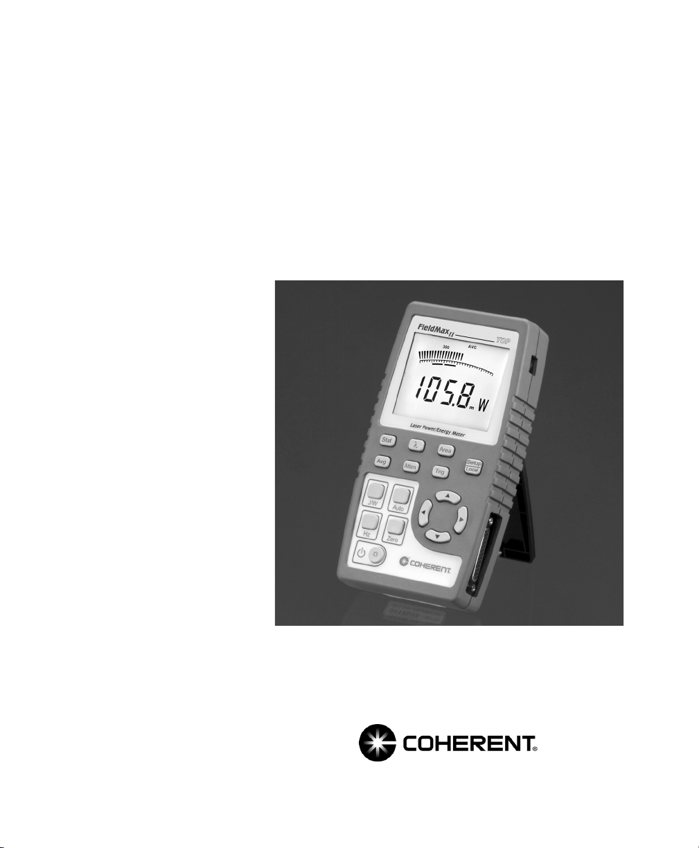
User Manual
FieldMaxII-TOP
Laser Power/Energy Meter
Page 2

Page 3

User Manual
FieldMaxII-TOP
Laser Power/Energy Meter
27650 SW 95th Ave.
Wilsonville, OR 97070
Page 4

FieldMaxII-TOP User Manual
This document is copyrighted with all rights reserved. Under
the copyright laws, this document may not be copied in whole
or in part or reproduced in any other media without the
express written permission of Coherent, Inc. Permitted copies
must carry the same proprietary and copyright notices as were
affixed to the original. This exception does not allow copies to
be made for others, whether or not sold, but all the material
purchased may be sold, given or loaned to another person.
Under the law, copying includes translation into another
language.
Coherent and the Coherent Logo are registered trademarks of
Coherent, Inc. FieldMaxII-TOP is a trademark of Coherent,
Inc.
Every effort has been made to ensure that the data given in
this document is accurate. The information, figures, tables,
specifications and schematics contained herein are subject to
change without notice. Coherent makes no warranty or
representation, either expressed or implied with respect to this
document. In no event will Coherent be liable for any direct,
indirect, special, incidental or consequential damages
resulting from any defects in its documentation.
Technical Support
In the U.S.:
Should you experience difficulties with your product, or need
technical information, please visit our website:
www.Coherent.com
either telephoning our Technical Support Hotline at
1.800.343.4912, or e-mailing our Support Team at
[email protected]. Telephone coverage is
available Monday through Friday (except U.S. holidays).
If you call outside our office hours, your call will be taken by
our answering system and will be returned when the office
reopens.
If there are technical difficulties with your product that cannot
be resolved by support mechanisms outlined above, please
. You can obtain additional support by
ii
Page 5

e-mail or telephone Coherent Technical Support with a
description of the problem and the corrective steps attempted.
When communicating with our Technical Support Department,
via the web or telephone, the model and serial number of the
product will be required by the Support Engineer responding
to your request.
Outside the U.S.:
If you are located outside the U.S., visit our website for
technical assistance, or telephone our local Service
Representative. Representative phone numbers and
addresses can be found on the Coherent website,
www.Coherent.com
Coherent provides web and telephone technical assistance as
a service to its customers and assumes no liability thereby for
any injury or damage that may occur contemporaneous with
such services. These support services do not, under any
circumstances, affect the terms of any warranty agreement
between Coherent and the buyer. Operating a Coherent
product with any of its interlocks defeated is always at the
operator's risk.
.
iii
Page 6

FieldMaxII-TOP User Manual
iv
Page 7

Table of Contents
TABLE OF CONTENTS
Preface .......................................................................................................... xi
RoHS Compliance ........................................................................................ xi
Software Installation ..................................................................................... xi
U.S. Export Control Laws Compliance ........................................................ xi
Publication Updates ..................................................................................... xii
Symbols Used in This Document ................................................................ xii
Safety ...................................................................................................................1
Waste Electrical and Electronic Equipment (WEEE, 2002)...........................2
Declaration of Conformity..............................................................................3
Quick Start.......................................................................................................5
Measuring Average Power With a Pyroelectric Sensor ..................................6
Measuring Power With a Thermopile or Optical Sensor................................7
Measuring Energy With a Pyroelectric Sensor ...............................................8
Measuring Energy With a Thermopile Sensor................................................9
Description ....................................................................................................11
Front Panel....................................................................................................13
Buttons .................................................................................................14
Display .................................................................................................15
Right Side Panel............................................................................................17
USB Connector ....................................................................................17
Sensor Connector.................................................................................17
Left Side Panel..............................................................................................18
Analog Out Connector .........................................................................18
Power Jack Connector .........................................................................18
Battery Replacement.....................................................................................19
Battery Directive..................................................................................19
AC Adapter ...................................................................................................20
v
Page 8

FieldMaxII-TOP User Manual
Operation ........................................................................................................21
Tuning Mode.................................................................................................22
Tuning Needles ....................................................................................23
Zone Indicator Bars .............................................................................24
Annunciators.................................................................................................26
Temperature .........................................................................................26
TRIG ....................................................................................................27
AUTO ..................................................................................................27
Range Hint ...........................................................................................27
AVG .....................................................................................................27
ATTEN.................................................................................................28
RMT.....................................................................................................28
Battery..................................................................................................28
Fault Displays ...............................................................................................29
Invalid and Not Available Data Conditions..................................................30
Invalid Data..........................................................................................30
Not Available Data...............................................................................30
Setup Parameters...........................................................................................31
Setup/Local ..........................................................................................31
Stat .......................................................................................................33
Wave ....................................................................................................33
Area......................................................................................................34
Area Correction and Zeroing ......................................................35
Avg.......................................................................................................36
Atten.....................................................................................................37
Trig.......................................................................................................37
Button Functions...........................................................................................38
J/W .......................................................................................................38
Auto .....................................................................................................38
Hz.........................................................................................................38
Zero......................................................................................................38
Power Switch and Backlight Toggle Button........................................39
Up and Down Arrows ..........................................................................40
Left and Right Arrows .........................................................................40
vi
Page 9

Table of Contents
Statistics Mode..............................................................................................40
Invalid Data..........................................................................................41
Energy and Power Measurements.................................................................42
Measurement Display and Range Selection .................................................44
Pyroelectric-Specific Information.................................................................48
Internal Triggering Mode.....................................................................48
Hz Display Mode .................................................................................50
Manual Ranging Mode ........................................................................50
Thermopile- and Optical-Specific Information ............................................51
Auto vs. Manual Ranging Mode..........................................................51
Zeroing.................................................................................................52
Special Topics ...............................................................................................53
Trigger States and the Trigger Annunciator..................................................53
Pulsed Thermopile Joules Mode...................................................................55
Pyroelectric Watts Mode...............................................................................56
Negative Power Display ...............................................................................57
Digital Tuning Feature Use in Statistics Mode.............................................58
ActiveX Installation......................................................................................58
USB Driver Installation ................................................................................58
Host Interface...............................................................................................59
Introduction...................................................................................................59
ActiveX Usage Guidelines............................................................................59
Usage Overview...................................................................................59
Coding Essentials.................................................................................61
Setup ...........................................................................................61
The Callback Object ...................................................................63
Status Change Notifications........................................................65
Data Transmission Notifications.................................................66
Error Callback.............................................................................69
Zero Status Callback...................................................................69
Teardown.....................................................................................70
Type Library Details ............................................................................71
vii
Page 10

FieldMaxII-TOP User Manual
Interface IFM2Listener ...............................................................72
Interface cFM2Listener...............................................................72
Interface IFM2DeviceEvents......................................................72
Interface cFM2ScanUSBForChange ..........................................74
Interface cFM2ScanForData.......................................................74
Interface IFM2Device.................................................................75
Interface cFM2Devices...............................................................86
Calibration and Warranty ...................................................................87
Calibration ....................................................................................................87
Coherent Calibration Facilities and Capabilities ..........................................88
Limited Warranty ..........................................................................................89
Extended Warranty........................................................................................89
Warranty Limitations ....................................................................................90
Obtaining Service .........................................................................................91
Product Shipping Instructions.......................................................................92
Appendix A: Specifications..................................................................93
Index ..................................................................................................................97
LIST OF TABLES
1. Batteries Contained in this Product ...........................................................19
2. Fault Codes ................................................................................................29
3. Numeric Display Information....................................................................43
4. Full Scale Range Settings - Joules Mode...................................................45
5. Full Scale Range Settings - Watts Mode....................................................46
6. Coherent Service Centers...........................................................................91
7. Specifications.............................................................................................93
viii
Page 11

Table of Contents
LIST OF FIGURES
1. Waste Electrical and Electronic Equipment Label.......................................2
2. Measuring Average Power With a Pyroelectric Sensor ...............................6
3. Measuring Power With a Thermopile or Optical Sensor.............................7
4. Measuring Energy With a Pyroelectric Sensor ............................................8
5. Measuring Energy With a Thermopile Sensor.............................................9
6. Front Panel.................................................................................................13
7. LCD Display ..............................................................................................15
8. Right Side Panel.........................................................................................17
9. Left Side Panel...........................................................................................18
10. Optional Alkaline Battery Replacement ....................................................20
11. Location of Tuning Needles and Zone Indicator Bars...............................22
12. Current Scale Mid-Range ..........................................................................23
13. Zone Indicator Bars ...................................................................................24
14. Comparison of Zone Indicator Bars to Full Scale Measurement...............25
15. Tuning Mode Example - Full Scale...........................................................26
16. Internal Trigger Threshold.........................................................................49
17. Auto Ranging.............................................................................................51
18. Measuring Energy - Pulsed Thermopile Joules Mode...............................55
19. Burst Power................................................................................................56
20. Burst Power Limitations ............................................................................57
ix
Page 12

FieldMaxII-TOP User Manual
x
Page 13

Preface
Preface
RoHS
Compliance
Software
Installation
This manual contains user information for the
FieldMaxII-TOP laser power/energy meter.
This Coherent product is RoHS compliant.
For complete software installation instructions, refer to
the FieldMaxII Software Installation Quick Start Guide
(1096359) that shipped with your product.
If that document is unavailable, insert the
FieldMaxII CD into your CD-ROM drive. If Autorun is
enabled on your system, installation will start automatically; otherwise, select Run from the Start menu and then
type D:\Setup.exe (substitute the appropriate letter of
your CD-ROM drive for D).
U.S. Export
Control Laws
Compliance
It is the policy of Coherent to comply strictly with U.S.
export control laws.
Export and re-export of lasers manufactured by Coherent
are subject to U.S. Export Administration Regulations,
which are administered by the Commerce Department.
In addition, shipments of certain components are regulated by the State Department under the International
Traffic in Arms Regulations.
The applicable restrictions vary depending on the
specific product involved and its destination. In some
cases, U.S. law requires that U.S. Government approval
xi
Page 14
FieldMaxII-TOP User Manual
be obtained prior to resale, export or re-export of certain
articles. When there is uncertainty about the obligations
imposed by U.S. law, clarification should be obtained
from Coherent or an appropriate U.S. Government
agency.
Publication
Updates
Symbols Used
in This
Document
To view information that may have been added or
changed since this publication went to print, connect to
www.Coherent.com.
This symbol is intended to alert the operator to the
presence of dangerous voltages associated with the
product that may be of sufficient magnitude to constitute a risk of electrical shock.
This symbol is intended to alert the operator to the
danger of exposure to hazardous visible and invisible
radiation.
This symbol is intended to alert the operator to the
presence of important operating and maintenance
instructions.
xii
Page 15
Safety
SAFETY
Carefully review the following safety information to
avoid personal injury and to prevent damage to this
meter or any sensor connected to it. Except for replaceable batteries (discussed under Battery Replacement
on page 19), there are no user-serviceable parts in the
FieldMaxII-TOP meter. For service information, refer to
Obtaining Service on page 91.
Use only the power cord specified for the meter. The
grounding conductor of the cord must be connected
to earth ground.
Do not operate the meter if its panels are removed or
any of the interior circuitry is exposed.
Do not operate the meter in wet or damp conditions,
or in an explosive atmosphere.
1
Page 16
FieldMaxII-TOP User Manual
Operate the meter only within the specified voltage
range.
Do not apply a voltage outside the specified range of
the input connections.
Do not operate the meter if there are suspected failures. Refer damaged units to qualified Coherent
service personnel.
Waste
Electrical and
Electronic
Equipment
(WEEE, 2002)
Figure 1. Waste Electrical and Electronic Equipment Label
The European Waste Electrical and Electronic Equipment (WEEE) Directive (2002/96/EC) is represented by
a crossed-out garbage container label. The purpose of
this directive is to minimize the disposal of WEEE as
unsorted municipal waste and to facilitate its separate
collection.
2
Page 17

Declaration
of Conformity
Safety
3
Page 18

FieldMaxII-TOP User Manual
4
Page 19
Quick Start
QUICK START
This section presents a series of mini-tutorials that
explains how to connect a sensor to your FieldMaxII-TOP meter and begin taking measurements
within minutes. For in-depth information about the
procedures introduced in this section, refer to Operation on page 21.
Follow all laser safety procedures. The laser must be
blocked or switched OFF before beginning any of the
procedures described in this section.
Power to the FieldMaxII-TOP instrument must be
OFF before beginning any of the procedures
described in this section.
Do not exceed the power/energy density limits of the
sensor.
5
Page 20
FieldMaxII-TOP User Manual
Measuring
Average
Power With a
Pyroelectric
Sensor
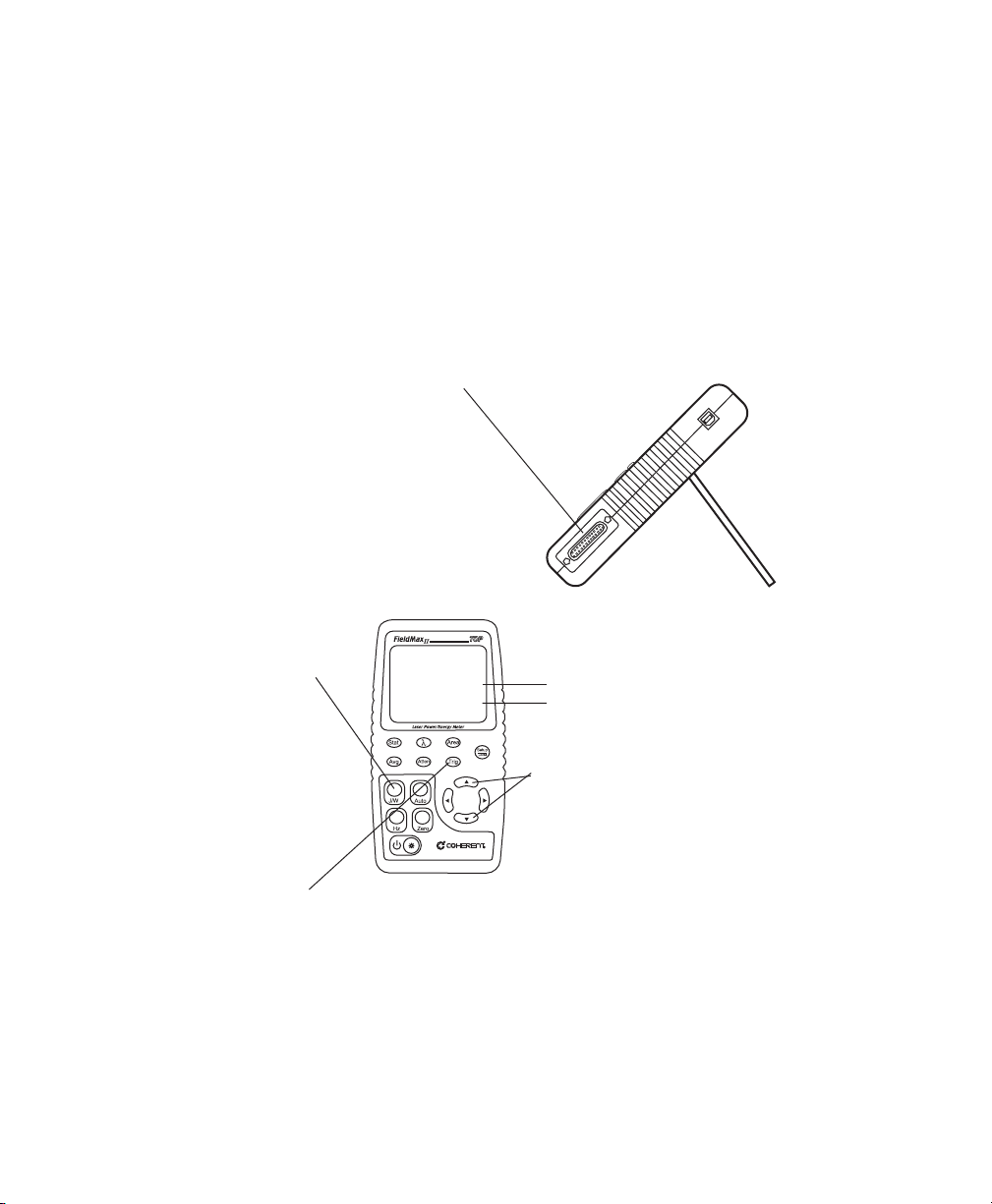
Connect a pyroelectric sensor to the
25-pin connector. Note: If your sensor
has a BNC plug, you will need to attach
a 25-pin adapter.
If Joules mode is currently
selected, press the J/W
button to select Watts mode.
The following figure shows how to set up a pyroelectric
sensor to take an average power measurement.
J (indicates Joules mode)
W
(indicates Watts mode)
Press either the Up or Down
arrow to manually select the range.
Note: Auto Range is not
available for this type of sensor.
Adjust the trigger threshold from 2 to 20% of range. Make sure the
trigger threshold is set below the energy you plan to measure.
Take the measurement and observe the result on the display.
Figure 2. Measuring Average Power With a Pyroelectric Sensor
6
Page 21
Quick Start
Measuring
Power With a
Thermopile or
Optical
Sensor
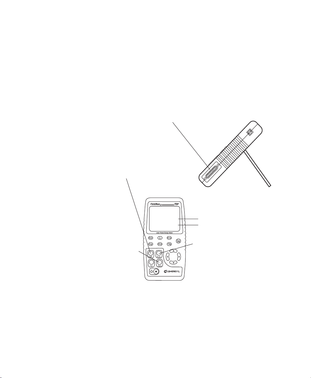
Connect a thermopile or optical
sensor to the 25-pin connector.
If Joules mode is currently
selected, press the J/W
button to select Watts mode.
The following figure describes how to take a power
measurement using a thermopile or optical sensor.
J (indicates Joules mode)
W
(indicates Watts mode)
Block the beam and then
press the Zero button to
set the baseline for your
new measurement.
Press the Auto button to
turn on Auto Range.
Unblock the beam, take the measurement, and observe the result on the display.
Figure 3. Measuring Power With a Thermopile or Optical Sensor
7
Page 22
FieldMaxII-TOP User Manual
Measuring
Energy With a
Pyroelectric
Sensor
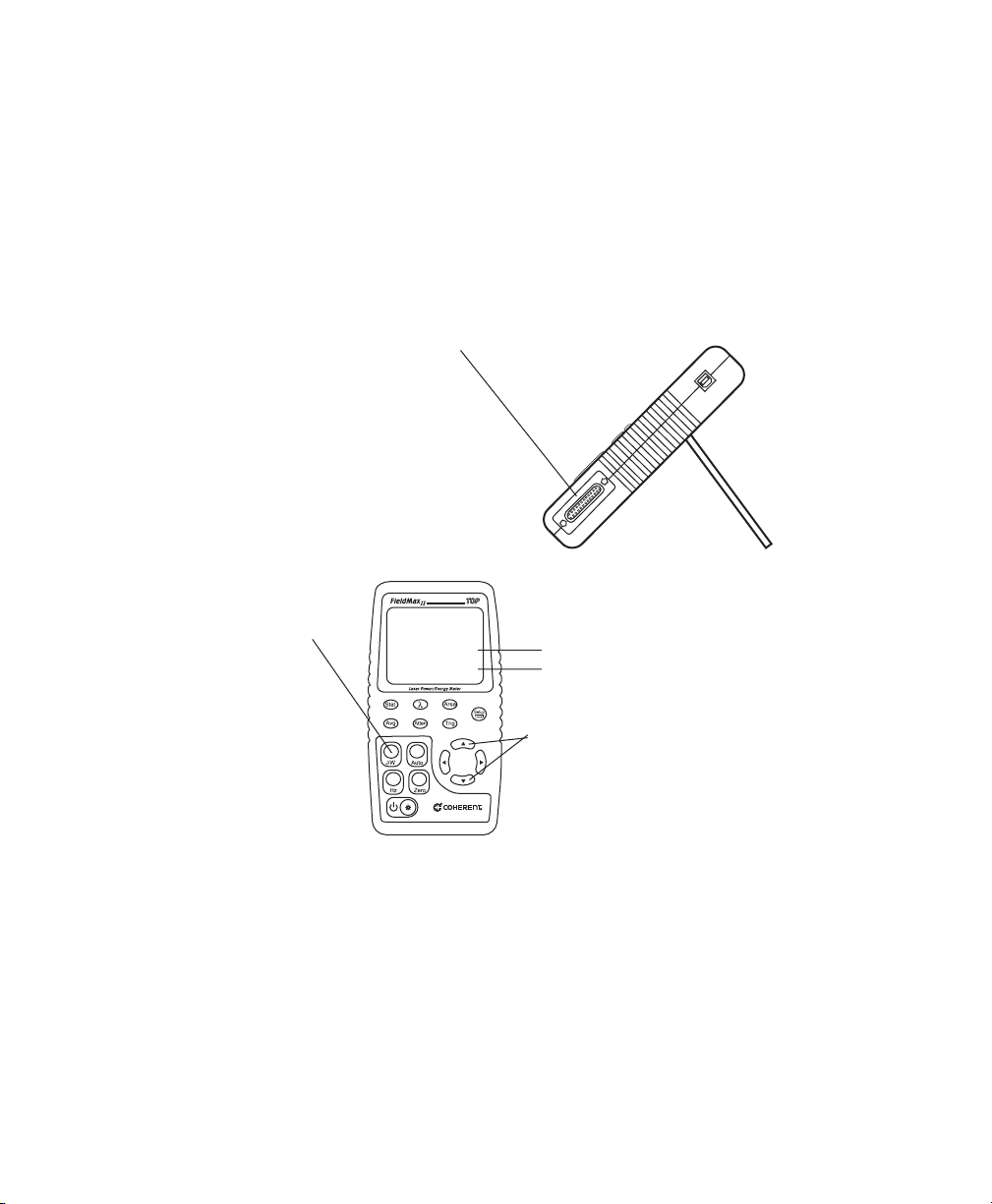
Connect a pyroelectric sensor to the
25-pin connector. Note: If your sensor
has a BNC plug, you will need to attach
a 25-pin adapter.
If Watts mode is currently
selected, press the J/W
button to select Joules mode.
The following figure outlines how to set up a pyroelectric sensor to take an energy measurement.
J (indicates Joules mode)
W
(indicates Watts mode)
Press either the Up or Down
arrow to manually select the range.
Note: Auto Range is not
available for this type of sensor.
Take the measurement and observe the result on the display.
Figure 4. Measuring Energy With a Pyroelectric Sensor
8
Page 23
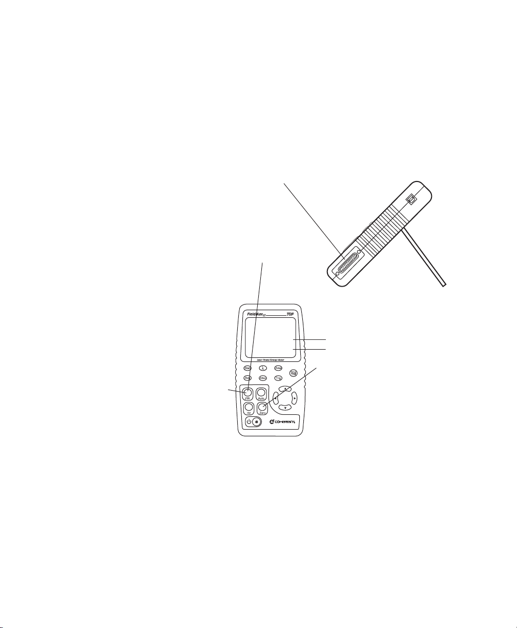
Quick Start
Measuring
Energy With a
The following figure explains how to take an energy
measurement using a thermopile sensor.
Thermopile
Sensor
Connect a thermopile sensor to
the 25-pin connector.
Press the J/W button to select Watts mode and
then find the appropriate watts range by taking
a couple of sample measurements. The
appropriate range is the lowest range
available that does not give an
overrange error during the test
measurement.
J (indicates Joules mode)
W
(indicates Watts mode)
Block the beam and then press the
Press the J/W button to select Joules
mode. The Range (Up and Down
arrows), Zero button, and Auto button
should not be used from this point on.
If an overrange error occurs, the range must be adjusted by returning to the Watts mode.
When FieldMax II-TOP is prepared for the first measurement, the TRIG? annunciator displays at the top of
the screen. The TRIG annunciator displays during the measurement, showing that the meter is currently
integrating the reading. The Zero button should not be pressed between measurements.
Expose the sensor to a laser pulse, take the measurement, and observe the result on the display.
Zero button to set the baseline for
your new measurement.
Figure 5. Measuring Energy With a Thermopile Sensor
9
Page 24

FieldMaxII-TOP User Manual
10
Page 25
Description
DESCRIPTION
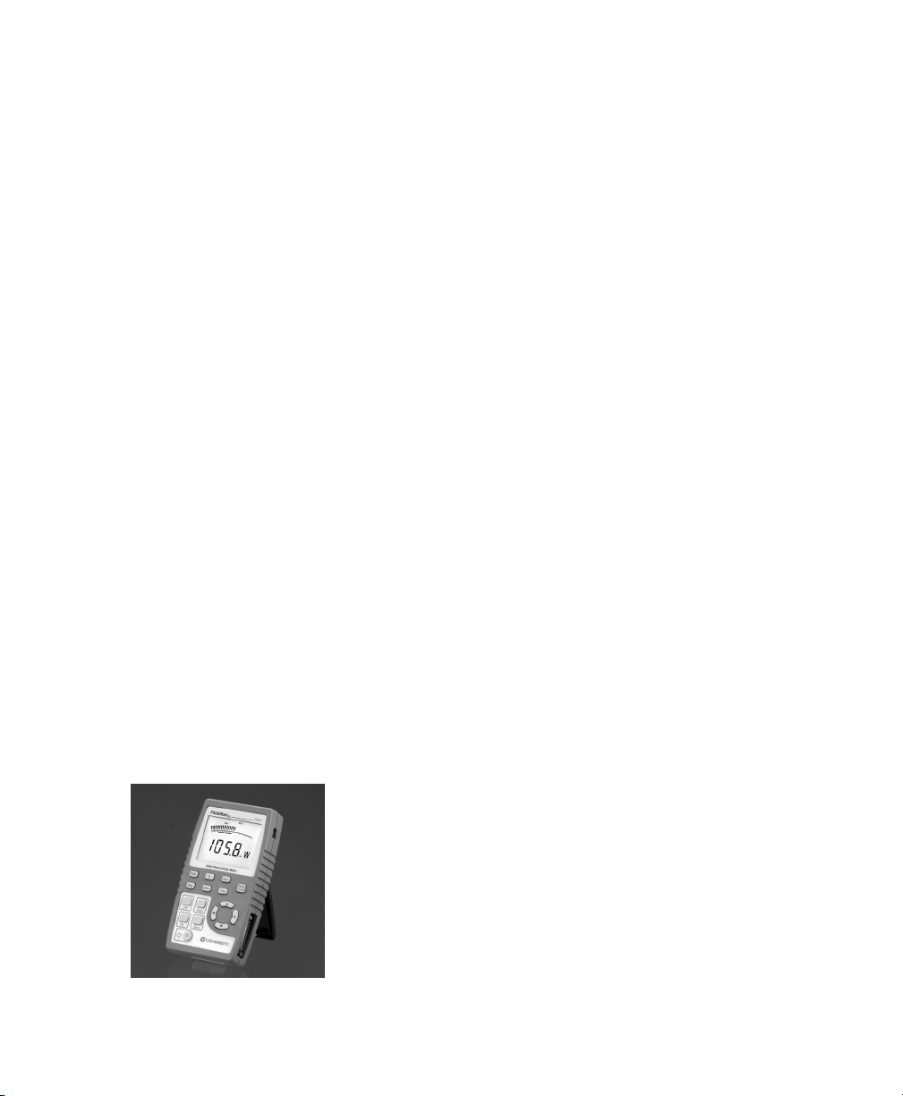
Thank you for purchasing the FieldMaxII-TOPa
versatile, easy-to-use digital power/energy meter
designed for field service and production applications.
This section discusses the following topics:
Front panel (page 13)
Right side panel (page 17)
Left side panel (page 18)
Battery replacement (page 19)
AC adapter (page 20)
There are also instructions on how to replace the alkaline
batteries (page 19) and a brief overview of the AC
adapter (page 20).
Here is a list of specific features included in your FieldMaxII-TOP meter:
73 x 58 mm backlit LCD display
Fast and effective laser tuning mode
Works with thermopile, pyroelectric, and optical
sensors
Measures energy up to 300 pps
Intuitive soft key-driven user interface
USB 1.1
11
Page 26

FieldMaxII-TOP User Manual
Portable AC/DC operation
Compact, rugged enclosure with stand
The versatile FieldMaxII-TOP measures:
Power: W, W/cm
Energy: J, J/cm
Frequency: Hz
Full statistics: max, min, mean, and standard devi-
2
2
ation
12
Page 27
Description
Stat
Avg Atten
Area
Trig
Auto
J/W
Hz
Zero
Front Panel
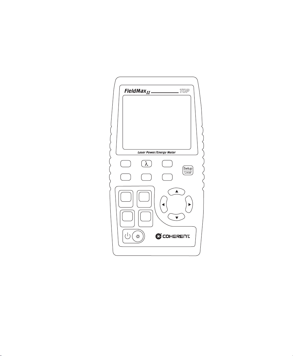
The front panel (shown in Figure 6) includes a liquid
crystal display (LCD) and buttons that are used to enter
parameters, select modes, and change ranges.
Figure 6. Front Panel
13
Page 28

FieldMaxII-TOP User Manual
Buttons
The following buttons are on the front panel of the FieldMaxII-TOP:
Setup/Localstarts or ends a parameter edit cycle.
This button is also used to cancel the front panel
lockout when Remote Control is active.
Statstatistics processing parameter
Wave (λ)wavelength compensation parameter
Areaarea correction parameter
Avgdisplay smoothing parameter
Attenattenuation correction parameter
Trigtrigger level parameter
J/WJoules or Watts mode
AutoAuto Ranging mode
HzRep Rate Display mode
Zerostart batch. When Statistics mode is not
active, this button can also be used to zero a sensor
(thermopile or optical), or restart a batch (pyroelectric).
Power Switch/Backlight Toggle button
Up Arrow ()field adjust or range select
Down Arrow ()field adjust or range select
Left Arrow ()field select
Right Arrow ()field select
For detailed information about each of these buttons,
refer to Operation on page 21.
14
Page 29
Description
Display
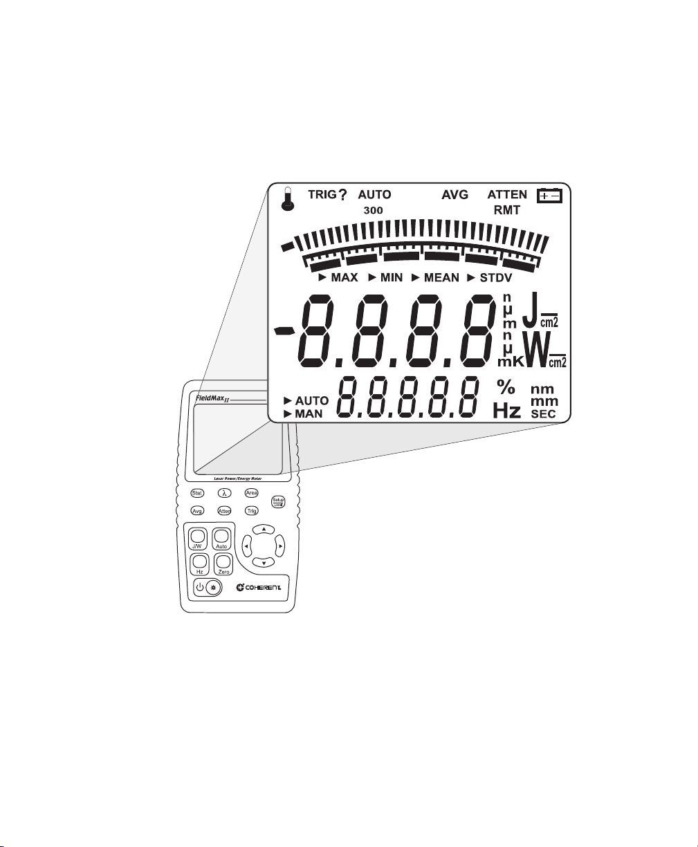
The LCD display provides visual measurement information. Figure 7 shows all the possible segments that may
appear on the display.
Figure 7. LCD Display
15
Page 30

FieldMaxII-TOP User Manual
The type of sensor being used and the individually-selected settings determine what type of information will actually appear on the display
Information that appears on the display is divided into
the groups described in the following list (Figure 7 on
page 15 shows the general location of each group).
Annunciators: Temperature, TRIG,AUTO, Range
Digital tuning feature
Tuning meter scale
Statistical parameters: MAX, MIN, MEAN, and
Numeric measurement valuelarge numeric char-
Hint, AVG, ATTEN, RMT, and Battery
STDV
acters
Measurement units and engineering prefixes
Statistical Sampling mode: AUTO and MAN
Numeric data entry, batch count, parameter
settings, and Hertz measurement values
Data entry units, Hertz units, and current parameter
units
For detailed information about these settings, refer to
Button Functions on page 38.
16
Page 31

Description
Right Side
Panel
USB Connector
The right side panel contains the USB and Sensor
connectors (refer to Figure 8).
Figure 8. Right Side Panel
Attaching the cableshipped with the meterto this
standard USB connector allows communication between
FieldMaxII-TOP and a computer with a USB interface.
Sensor
Connector
Use this connection to attach a DB-25 SmartProbe
connector or adapter.
17
Page 32

FieldMaxII-TOP User Manual
r
Left Side
Panel
Analog Out
Connector
The left side panel contains the Analog Out and Power
Jack connectors (refer to Figure 9).
Analog Out Connector
Power Jack Connecto
Figure 9. Left Side Panel
When power is on, the Analog Out connector outputs a
voltage proportional to the current laser measurement.
The output voltage is zero (0) volts when the measured
energy or power is zero (0) or less. The output voltage is
the full-scale output voltage when the measured energy
or power is full-scale or overranged. The full-scale
output voltage (1V, 2V, or 5V) is selected via the host
interface. Factory default full-scale output voltage is 2V.
Power Jack
Connect the supplied power cord to this jack.
Connector
18
Page 33

Description
Battery
Replacement
Battery
Directive
Table 1. Batteries Contained in this Product
7.2V rechargeable battery pack NiMH
(optional) 1.5V Alkaline
FieldMaxII-TOP uses a rechargeable battery pack (standard), six 1.5V alkaline batteries, or a 90-to-260 VAC,
50/60 Hz AC adapter (refer to AC Adapter on page 20
for more information). Figure 10 illustrates how to
replace the optional alkaline batteries.
The batteries used in this product are in compliance with
the EU Directive 2006/66/EC (EU Battery Directive).
DESCRIPTION TYPE
Dispose of batteries according to local regulations. Do not dispose as normal waste.
Consult your local waste authorities for
guidance.
19
Page 34

FieldMaxII-TOP User Manual
Figure 10. Optional Alkaline Battery Replacement
AC Adapter
Using an AC adapter prolongs battery life. FieldMaxII-TOP automatically senses when an adapter is
used.
When batteries rather than an adapter, are used, the
Battery annunciator flashes if the battery charge is low.
While in battery operation, if a sensor is not connected to
the meter, power is automatically turned off after ten
minutes.
20
Page 35

Operation
OPERATION
This section discusses the following topics:
Tuning mode (page 22)
Annunciators (page 26)
Fault displays (page 29)
Invalid and not available data conditions (page 30)
Setup parameters (page 31)
Button functions (page 38)
Statistics mode (page 40)
Energy and power measurements (page 42)
Measurement display and range selection
(page 44)
Pyroelectric-specific information (page 48)
Thermopile- and optical-specific information
(page 51)
21
Page 36

FieldMaxII-TOP User Manual
T
uning Needles
Zone
s
Tuning Mode
This mode only works in Manual Ranging mode. For
more information about ranging, refer to Manual
Ranging Mode on page 50 (if you are using a pyroelectric sensor), or Auto vs. Manual Ranging Mode
on page 51 (if you are using a thermopile or optical
sensor).
As shown in Figure 11, tuning is visually displayed on
the LCD using tuning needles and zone indicator bars.
Indicator Bar
Figure 11. Location of Tuning Needles and Zone Indicator Bars
22
Page 37

Operation
f
Curre
Scale
Tuning Needles
Tuning needleswhich divide a given tuning zone into
thirty incrementsare used to peak a laser output. As
the top or bottom of a zone is reached, the tuning needles
automatically move to the center of the next zone (see
Figure 12). Zone indicator bars let you know when this
happens (refer to Zone Indicator Bars on page 24 for
more information).
Mid-Range o
nt
Figure 12. Current Scale Mid-Range
23
Page 38

FieldMaxII-TOP User Manual
s
Zone Indicator
Bars
Zone indicator bars are a series of six segments, as shown
in Figure 13:
Zone Indicator Bar
Figure 13. Zone Indicator Bars
These bars act as visual indicators while the tuning
needles automatically move through zones, and also
provide a relative indication of where the measurement
falls within the active range.
24
Page 39

Operation
Zone indicator bars always appear in pairs, with each
overlapping zone representing 1/3 of full scale.
Figure 14 shows how the five zone indicator bars correlate to full scale measurement on the tuning meter scale.
Figure 14. Comparison of Zone Indicator Bars to Full Scale Measurement
25
Page 40

FieldMaxII-TOP User Manual
Figure 15 shows an example of how the zone indicator
bars overlap on a 30-watt scale:
Figure 15. Tuning Mode Example - Full Scale
Annunciators
Temperature
Annunciators refers to the icon-type symbols that appear
on the LCD (Figure 7 on page 15 shows all the annunciators on the FieldMaxII-TOP meter). The update rate for
all annunciators is 3 times per second.
(thermopile sensors only) The Temperature annunciator flashes whenever the meter detects a sensor
over-temperature condition. This annunciator is not
visible unless a sensor over-temperature condition exists.
26
Page 41

Operation
TRIG
AUTO
Range Hint
Whenever a trigger is detected, TRIG displays in the
TRIG annunciator position. TRIG? displays in the
absence of a trigger.
The TRIG annunciator applies under the following
conditions:
A pyroelectric sensor is attached.
A thermopile sensor is attached and Joules mode is
active.
(thermopile and optical sensors only) The AUTO annun-
ciator displays the state of the auto ranging of the meter.
Auto Ranging is active when AUTO displays. If Auto
Ranging is not active, or a pyroelectric sensor is attached
to the meter, the AUTO annunciator is not visible.
The Range Hint annunciatortowards the top of the
LCD, just above the tuning needlesdisplays 3, 30,
or 300. These numbers represent the full-scale range
currently selected by the user. Range Hint is discussed in
more detail under Measurement Display and Range
Selection on page 44.
AVG
When AVG (display smoothing) is active, display values
are averaged (by samples) for pyroelectric sensors, and
(by time) for thermopile and optical sensors. AVG
displays when averaging is active. Nothing displays in
this position if averaging is not active.
27
Page 42

FieldMaxII-TOP User Manual
ATTEN
RMT
Battery
The ATTEN annunciator indicates if attenuation correction is applied to the measurement value. ATTEN
displays whenever attenuation is active.
The RMT annunciator indicates that the FieldMaxII
meter is currently in Remote Control mode. Remote
Control is discussed under Setup/Local on page 31.
The Battery annunciator flashes whenever
the batteries need to be replaced.
The Battery annunciator only appears when the
meter is running on battery power, not the AC
adapter.
28
Page 43

Operation
Fault Displays
Unrecognized sensor 1
Sensor communication failure 2
Sensor error 3
Sensor error 4
Sensor/firmware version mismatch (sensor
format version exceeds capability of the instrument firmwarefirmware upgrade needed)
FieldMaxII-TOP is capable of detecting internal and
user-induced faults. When a fault is detected, the letters
Erfollowed by a numeric fault code (see
Table 2)appear on the display. You can dismiss a fault
code by pressing any button, or by correcting the cause
of the fault.
Table 2. Fault Codes
ERROR CONDITION FAULT CODE
5
Sample rate fault 6
Hardware fault (detectable hardware error) 20
Bad zero
Data overflow (result of an arithmetic operation that is greater than can be held in the allocated storage)
Wrong type of sensor is attached to the instrument
a. For more information about the bad zero fault code, refer to Zero on
page 38.
a
29
40
41
42
Page 44

FieldMaxII-TOP User Manual
As an example, Er 4 appears on the display if there is
a sensor error. You can dismiss the fault by removing the
sensor from the meter, or by pressing any button.
Attaching an unrecognized sensor to the meter creates a
special fault condition. This condition is characterized by
displaying a sensor fault (1 through 5).
Invalid and
Not Available
Data
Conditions
Invalid Data
Not Available
Data
The update rate for invalid or not available data conditions is three times per second.
Invalid data is obtained whenever the meter over-ranges.
When invalid data is sensed, the letters OL (overload)
appear on the display. If OL appears while in Auto
mode, no further action needs to be taken. If OL
appears while in Manual mode, start a new batch by
pressing the Zero button. All data used to generate a
batch result must be valid.
Measurement data may be unavailable at certain times
during meter operation. When data is not available, a
series of dashes appears in the measurement area of the
display. The following conditions will generate unavailable data:
Meter is powered on and no pulse triggers are
detected with a pyroelectric sensor.
30
Page 45

Operation
Function mode (Joules or Watts) is changed and no
pulse triggers are detected with a pyroelectric
sensor.
Statistics mode is entered and batch data has not
been compiled.
Setup
Parameters
Setup/Local
This section explains how to select and set user-definable
parameters.
The Setup/Local button serves several purposes:
1. If an edit cycle is not in progress, pressing the
Setup/Local button initiates an edit cycle. If the
next button pressed represents an edit parameter
(STAT, WAVE, AREA, ATTEN, TRIG, or AVG
button), Edit mode is entered and the parameter for
the applicable button may be edited using the edit
buttons. Additional presses of the Setup/Local
buttonwithout first pressing an edit parameter
buttonare ignored.
2. If a parameter has not been selected, pressing the
Setup/Local button cancels an edit cycle.
3. If Edit mode is active and a parameter has been
selected, pressing the Setup/Local button commits
the adjusted edit parameter to the instrument.
31
Page 46

FieldMaxII-TOP User Manual
4. Setup/Local is used to cancel the front panel
Remote Control is active when the instrument is
connected to a host computer via a USB connection
and is communicating with a host application
program. While the instrument is in Remote Control
mode, all front panel buttonsexcept Power/Backlight and Setup/Localare disabled. Pressing the
Setup/Local button while in Remote Control mode
cancels Remote Control and returns the instrument
to Local (all instrument functions available) mode.
The Setup/Local button is also used to edit user-defined
parameters. Pressing this button initiates a parameter edit
cycle.
A parameter edit cycle consists of:
lockout when Remote Control is active.
Pressing the Setup/Local button to begin the cycle.
Pressing the parameter button (Stat, Wave (λ),
Area, Avg, Atten, or Trig) that needs to be edited.
If an edit cycle has been initiated, successive
presses of the same edit parameter button will be
ignored.
Using the arrow buttons to select the appropriate
field and adjust the data value.
Pressing the Setup/Local button a second time to
end the cycle and commit the new data value.
32
Page 47

Operation
Stat
Wave
Pressing the Stat button will:
Enter Statistics modeif Statistics mode is not
active and the button is pressed for less than two
seconds.
Exit Statistics mode.
Enter Edit mode and select the statistics parameters
to be edited (Batch Size and Restart mode) after
edit cycle initiation (if Setup/Local is pressed
beforehand). Batch size is 2 to 99,999 pulses (thermopile sensors in Joules mode, or pyroelectric
sensors), or 1 to 99,999 seconds (thermopile
sensors in Watts mode, or optical sensors).
View the statistics parameters if the button is
pressed for two seconds or more.
You can configure FieldMaxII-TOP to automatically account for any difference between the laser
wavelength and the calibration wavelength. In the
case of optical sensors, this compensation is necessary
because the sensor contains calibration data from a
number of different wavelengths. Thermopile and
optical sensors include wavelength compensation information that is used in this mode.
After pressing Setup/Local, the Wave button is used to
enter Edit mode and set the wavelength. If an edit cycle
has not been initiated, pressing the Wave button will
33
Page 48

FieldMaxII-TOP User Manual
display the wavelength value. The available wavelength
range is 1.00 to 99,999 nm. The actual range is sensordependent.
If Wavelength compensation information is not
programmed into the sensor, you will not be able to
change the wavelength data value.
Area
This mode allows the measurement of laser energy in
terms of fluence, and laser power in terms of average
power density.
Area calculation returns an average power density
reading for both Flat and Gaussian profiles.
The parameter is entered as a diameter and assumes a
circular beam or aperture. The range for Area mode is
0.01 to 999.99 mm.
Pressing the Area button will:
Toggle the state of Area Correction mode, if the
button is pressed for less than one second. Refer to
Area Correction and Zeroing on page 35 for
more information about Area Correction mode.
Enter Edit mode and select the beam diameter, if
Setup/Local is pressed beforehand.
View the beam diameter, if the button is pressed for
one second or more.
34
Page 49

Operation
Area Correction
and Zeroing
(thermopile and optical sensors only)
It is important that you zero the sensor before using
Area Correction, as explained in the following procedure.
1. Enter Area Correction by pressing the Area button
for less than one second.
2. Set Auto Ranging by pressing the Auto button.
3. Block the sensor beam.
4. Allow the sensor to enter a steady (cool-down)
state. If you are using a thermopile sensor, this
steady state can be determined by watching the
display numbers on the LCD. At first the numbers
will decrease quickly but, as the sensor cools, the
numbers decrease more slowlythe slower the
decrease, the cooler the sensor, and the cooler the
sensor, the more accurate the area correction
reading will be. Optical sensors do not require a
cool-down period.
5. Press the Zero button.
The sensor is now zeroed. For more information about
zeroing, refer to Zeroing on page 52.
35
Page 50

FieldMaxII-TOP User Manual
Avg
Average mode enables display smoothing, which
suppresses variations in the display reading that can
make it difficult to read.
Display values are averaged either by time (for thermopile or optical sensors), or by pulses (for pyroelectric sensors).
You can change the size of the display smoothing
window. With an attached thermopile or optical sensor,
the window size is 1 to 60 seconds. Using a pyroelectric
sensor, the window size is 2 to 1,000 pulses.
Averaging displays live measurements while the first
batch is being acquired. Following the first batch, each
reading appears on the display as an average of the batch
(window) size. Example: Using a 10-second batch size,
the first ten seconds are measured live. The next reading
that appears on the display is an average of the measurements taken during the 1- to 10-second time frame,
followed by a reading that is the average of the measurements taken during the 11- to 20-second time frame, etc.
The Avg button is used to:
Toggle the state of Average mode (if the button is
pressed for less than one second).
Enter Edit mode and select the display smoothing
window size (if Setup/Local is pressed beforehand).
View the display smoothing window size (if the
button is pressed for one second or more).
36
Page 51

Operation
Atten
Attenuation mode allows you to get true measurements
using an attenuator that has a known attenuation factor.
When Attenuation Correction mode is enabled, the
measured value is adjusted to indicate the measurement
at the attenuator and not the sensor. The range for this
mode is 0.01 to 999.99.
Heres an example of how to determine the attenuation
correction factor that needs to be set in the FieldMaxIITOP meter: If a 1 W laser beam is focused through an
attenuator that has an attenuation factor of 50%, then, to
get a true laser measurement value, the correction factor
in the FieldMaxII-TOP instrument needs to be set to 2. In
other words, since only half the power of the beam is
transmitted through the attenuator, the measured result
must be doubled to obtain a true laser measurement.
The Atten button is used to initiate several activities:
Toggle the state of Attenuation Correction mode, if
the button is pressed for less than one second.
Enter Edit mode and select the attenuation factor, if
Setup/Local is pressed beforehand.
Trig
View the attenuation factor, if the button is pressed
for one second or more.
After pressing the Setup/Local button, the Trig button is
used to enter Edit mode and select the trigger level
parameter that will be edited. If an edit cycle has not been
initiated, pressing the Trig button will display the trigger
level parameter. Trigger has a range of 2 to 20% of full
scale. Refer to Internal Triggering Mode on page 48
for details of the trigger function
37
Page 52

FieldMaxII-TOP User Manual
Button
Functions
J/W
Auto
Hz
Zero
The main function of this button is to toggle between
Joules and Watts mode. Only Watts mode can be active
when an optical sensor is attached.
(thermopile and optical sensors only) Pressing the Auto
button instructs the FieldMaxII-TOP to select the best
measurement range for the incoming signal.
(pyroelectric sensors only) Pressing the Hz button
toggles the Pulse Frequency Display mode. If Hz mode
is on, the pulse frequency displays in the parameter edit
region of the display. If Hz mode is off, the pulse
frequency does not display. If the pulse frequency is
>300 Hz, the displays shows a series of three dashes,
followed by the letters, Hz.
(thermopile and optical sensors only) Pressing the Zero
button causes the analog circuitry to zero its internal
settings by running a zero cycle. If Auto Ranging is not
active, the meter will zero the currently-selected range. If
Auto Ranging is active, the meter will zero all available
ranges for the attached sensor. When a zero procedure is
in process, no other button events are queued or activated
38
Page 53

Operation
until the procedure ends. The zero procedure is immediately terminated if the sensor is disconnected or if an
error is encountered.
Normally, the Zero button is pressed with the laser
blocked from the connected sensor. If a finite power level
is present at the sensor, the instrument will attempt to
null it out. A bad zero fault code appears if a given power
input is too large to null on the sensitive ranges.
If the bad zero fault code appears:
Press any soft button to dismiss the error
Select a new range
Press the Zero button
The secondary function of the Zero button is to manually
start a batch while in Statistics mode.
Power Switch
and Backlight
Toggle Button
The combination Power Switch and Backlight
Toggle button serves the dual purpose of
turning power on/off to the meter, and
toggling the backlight.
When the meter is off, the power-on state is acti-
vated by pressing the button for one second.
Pressing the button for one second while in the
power-on state turns the meter off.
When the meter is in the power-on state, the back-
light state is toggled by pressing the button for less
than one second.
The backlight is always off when power is first
applied to the meter.
39
Page 54

FieldMaxII-TOP User Manual
Up and Down
Arrows
Left and Right
Arrows
Statistics
Mode
These buttons serve a dual purpose. When Edit
mode is active, the buttons are used to adjust the
currently-selected edit field. When Edit mode is
not active, the buttons are used to select the measurement
range and automatically cancel Auto Range mode, if
Auto Range mode is active.
This button pair has a dual purpose. When the
Edit mode is active, the buttons allow you to
select the edit field of the currently-selected edit
parameter. When the Edit mode is not active and Statistics mode is active, the buttons are used to select the
statistical parameter of interest (MAX, MIN, MEAN, or
STDV). These buttons are nonfunctional when Edit
mode and Statistics mode are not active.
FieldMaxII-TOP can be configured to display statistical
data instead of instantaneous measurements. Statistical
data for a pyroelectric sensor is generated on a pulse-bypulse basis. Using a thermopile or optical sensor, statistical data is generated over time.
An exception to the above statement: When using a
thermopile sensor with the instrument in Joules
mode, energy is measured as integrated power from
individual laser pulses.
40
Page 55

Operation
Selecting Auto mode restarts the batch count used to take
a reading. If the instrument is not in Auto mode, the batch
count must be manually restarted by pressing the Zero
button.
Pressing and holding the Stat button displays the
current instrument mode: Auto or Manual.
For more information on selecting parameters while in
Statistics mode, refer to Left and Right Arrows on
page 40.
Invalid Data
A statistical batch requires valid data for every data point
in the batch. If a batch collection of data is in process and
invalid data is measured, the batch is considered contaminated and the batch immediately ends with no batch
result computed. If the Restart mode is Auto, a new batch
is immediately restarted. The error that caused the
contaminated batch is displayed.
41
Page 56

FieldMaxII-TOP User Manual
Energy and
Power
Measurements
Energy (joules) measurements are taken using pyroelectric sensors (for pulsed laser) or thermopile sensors (for
long-pulsed laser). The user interface behaves in a
slightly different manner, depending on which type of
sensor you are using. Energy measurements cannot be
taken with an optical sensor.
When using a thermopile sensor in long pulse Joules
mode, energy is measured as integrated power from
individual laser pulses. For more information, refer
to Pulsed Thermopile Joules Mode on page 55.
Power (watts) measurements are taken using either pyroelectric sensors (for pulsed laser), or thermopile and
optical sensors (for continuous laser).
A speedup algorithm is used while taking power
measurements with a thermopile sensor. This algorithm is applied to the tuning needles to provide
faster response while tuning a laser. Refer to Tuning
Mode on page 22. To improve accuracy, speedup is
not applied to the numeric measurements.
As with energy measurements, there are slight variations
in the user interface, depending on which type of sensor
you are using.
42
Page 57

Table 3 describes the measured information on the
numeric display for various sensor types and mode
settings.
Table 3. Numeric Display Information
SENSOR TYPE J MODE W MODE
Operation
Thermopile Energy from a laser pulse by
integrating power
Meter and Range Hint
unavailable
Auto Range disabled
Statistics mode: MAX, MIN,
MEAN
Optical Function not available CW power
Pyroelectric Energy per pulse Average power delivered
Statistics mode: MAX, MIN,
MEAN, STDV
a. In this mode, standard deviation is only available if the batch size is 200 or less.
a
CW and average power
Statistics mode: MAX, MIN,
MEAN
Statistics mode: MAX, MIN,
MEAN
by repeating pulses
Range Hint unavailable
Statistics mode: MEAN
43
Page 58

FieldMaxII-TOP User Manual
Measurement
Display and
Range
Selection
The display update rate for numeric measurement is
three times per second.
Measurement range is selected in decade steps. Range
selection (shown in Table 4 on page 45, and Table 5 on
page 46) is dependent on the sensor type and characteristics, as well as user-determined measurement settings.
FieldMaxII-TOP uses the 3s Rulea display format-
ting rule in which the display value is not allowed to
exceed 3, 30, or 300, depending on where the decimal
point falls, with the decimal point located in a fixed position, as determined by the current range. Typically if a
reading exceeds the 3s limit, the instrument is overranged or, in the case of Auto Ranging, the instrument
will automatically range up.
44
Page 59

Over-ranging refers to a meter setup condition in which
the sensor output signal is greater than the maximum
allowable level for the selected range. An OL (overload) appearing on the display signifies an over-range
condition. Over-ranging generates invalid data.Table 4
indicates the display format for different full-scale range
settings when in Joules mode.
Table 4. Full Scale Range Settings - Joules Mode
FULL SCALE MEASUREMENT DISPLAY FORMAT
3 nJ X.YYY nJ
30 nJ XX.YY nJ
300 nJ XXX.Y nJ
3 μJ X.YYY μJ
30 μJ XX.YY μJ
Operation
300 μJ XXX.Y μJ
3 mJ X.YYY mJ
30 mJ XX.YY mJ
300 mJ XXX.Y mJ
3 J X.YYY J
30 J XX.YY J
300 J XXX.Y J
When area correction is enabled in Joules or Watts
mode, a /cm2 will be appended to the units.
45
Page 60

FieldMaxII-TOP User Manual
The Range Hint annunciator displays the full-scale range
value with the engineering prefix and units omitted. For
example, when the range is 30 J, the Range Hint annunciator displays 30. Note that it also displays 30 when
the selected range is 30 mJ, 30 μJ, or 30 nJ. For more
information about the Range Hint annunciator, refer to
Range Hint on page 27.
Table 5 indicates the display format for different fullscale range settings when in Watts mode.
Table 5. Full Scale Range Settings - Watts Mode (Sheet 1 of 2)
FULL SCALE MEASUREMENT DISPLAY FORMAT
3 nW X.YYY nW
30 nW XX.YY nW
300 nW XXX.Y nW
3 μW X.YYY μW
30 μW XX.YY μW
300 μW XXX.Y μW
3 mW X.YYY mW
30 mW XX.YY mW
300 mW XXX.Y mW
3 W X.YYY W
30 W XX.YY W
300 W XXX.Y W
46
Page 61

Table 5. Full Scale Range Settings - Watts Mode (Sheet 2 of 2)
FULL SCALE MEASUREMENT DISPLAY FORMAT
3 kW X.YYY kW
300 kW XX.YY kW
The Range Hint annunciator displays the full-scale range
value with the engineering prefix and units omitted. For
example, when the range is 30 kW, the Range Hint
annunciator displays 30. Note that it also displays 30
when the selected range is 30 W, 30 mW, 30 μW, or 30
nW. For more information about the Range Hint annunciator, refer to Range Hint on page 27.
Operation
47
Page 62

FieldMaxII-TOP User Manual
PyroelectricSpecific
Information
Internal
Triggering
Mode
Information in this section pertains exclusively to pyroelectric sensors. If you are using a thermopile or optical
sensor, refer to Thermopile- and Optical-Specific Infor-
mation on page 51.
For greatest accuracy and repeatability, FieldMaxII-TOP
must trigger reliably for each laser pulse. Internal trig-
gering refers to extracting an artificial trigger from the
incoming signal.
To successfully extract an internally-generated trigger,
set the meter range so that the incoming signal is at least
5% of the full scale. Set the trigger level at least 2%
above the noise level and at least 2% below the peak
height.
For example, with a peak height of 300 mJ, set the meter
to a range of 3 J. A peak will occur at 10% of full scale,
well above the 5% level. The trigger level should not be
set higher than 8%. If the noise level is 5% of full scale
(approximately 150 mJ), the trigger level should not be
set lower than 7%.
48
Page 63

Operation
In the example shown in Figure 16, the internal trigger
threshold has been set to 8% (shown as a dashed line).
Pulse A will definitely not generate a reliable trigger.
Pulse B may generate a trigger, but not reliably. Pulses C
and D will definitely generate reliable triggers.
Figure 16. Internal Trigger Threshold
A full-scale signal on one range may not trigger on the
next higher range unless the trigger level is set to less
than 10%. For example, a near full-scale signal of 280 mJ
on the 300 mJ range is less than 10% of full scale on the
next higher range (3 J), and would therefore not trigger
the reading. To obtain reliable triggering in this instance,
adjust the trigger level to less than 8%.
49
Page 64

FieldMaxII-TOP User Manual
The trigger is synchronous with the leading edge of the
pulse, but the actual peak is determined algorithmically
by sampling the input signal near the trigger. From the
trigger point forward, the algorithm searches for peaks
and from the trigger point back, it searches for a baseline.
Hz Display
Mode
Manual
Ranging Mode
If desired, pulse frequencies may be displayed when a
pyroelectric sensor is attached to the meter. For more
information, refer to Hz on page 38.
(thermopile or optical sensors only) Manual ranging
requires the user to select the range. For more information about manual ranging, refer to Up and Down
Arrows on page 40.
50
Page 65

Operation
T
uning Needles
Thermopileand OpticalSpecific
Information
Auto vs. Manual
Ranging Mode
Information in this section pertains exclusively to thermopile and optical sensors. If you are using a pyroelectric sensor, refer to Pyroelectric-Specific Information
on page 48.
Auto Ranging (Auto) enables FieldMaxII-TOP to automatically select the range (gain) when a thermopile or
optical sensor is attached to the meter. While in Auto
Ranging mode, the tuning needles represent a zero-tofull scale movement (as compared to Tuning mode,
where the zones overlap). Refer to Figure 17.
Figure 17. Auto Ranging
Manual ranging requires the range to be selected by
the user. For more information, refer to Up and
Down Arrows on page 40.
51
Page 66

FieldMaxII-TOP User Manual
Zeroing
Thermopile and optical sensors require periodic zeroing.
Zeroing occurs when a meter attempts to null out any
signal coming from the sensor and establish a zeropower baseline. If Auto Ranging is active, the sensor is
zeroed for every available range. If Auto Ranging is not
active, the sensor is zeroed at the current range only.
Under typical operating conditions, the zero procedure
takes about one second for each range.
When starting the zeroing procedure, the large numerals
on the LCD are replaced by an animated set of dashes.
Unless there is an error, the normal measurement mode
resumes once the zeroing procedure ends.
52
Page 67

Special Topics
SPECIAL TOPICS
This section discusses the following topics:
Trigger states and the trigger annunciator (this
page)
Pulsed thermopile Joules mode (page 55)
Pyroelectric Watts mode (page 56)
Negative power display (page 57)
Digital tuning feature use in Statistics mode
(page 58)
ActiveX installation (page 58)
USB driver installation (page 58)
Trigger States
and the
Trigger
Annunciator
Two segments are dedicated to the indication of the
trigger state of the meter. These are the TRIG and the ?
segment that follows it. The trigger state is always used
when a pyroelectric sensor is attached.
There are two possible trigger states when a pyroelectric
sensor is attached: triggered and wait for trigger. The
triggered state indicates that the meter is capturing laser
pulses. The wait for trigger state indicates an absence of
pulse triggers. When a pulse is captured, the trigger state
becomes active and the wait for trigger state becomes
inactive. If no pulses are captured within 1.67 seconds
since the last pulse was captured, the wait for trigger state
53
Page 68

FieldMaxII-TOP User Manual
becomes active and the triggered state becomes inactive.
The TRIG annunciator reads TRIG in the triggered
state and TRIG? in the wait for trigger state.
There are two possible states when a thermopile sensor is
attached and Joules mode is active: integrating and
wait for trigger. The integrating state indicates that
laser power is being integrated to produce a final energy
measurement. The wait for trigger state indicates the
meter is waiting for a power pulse to integrate. When the
meter detects a power pulse trigger, the integrating state
becomes active and the wait for trigger state becomes
inactive. The integrating state persists until the power
signal decays to the point where the tail energy can be
predicted. At that point the wait for trigger state becomes
active and the integrating state becomes inactive. The
TRIG annunciator reads TRIG in the integrating state
and TRIG? in the wait for trigger state.
54
Page 69

Special Topics
Pulsed
Thermopile
Joules Mode
Trigger Point
(for long-pulsed lasers only) When a thermopile sensor
is attached, the meter has the capability of measuring
energy from a finite duration laser pulse, or from a series
of finite duration laser pulses. (Thermopile sensors are
typically used to measure laser power and have an
extremely slow response time relative to the pulse width
of the laser used to generate the power signal.)
The power curve (refer to Figure 18) is integrated from
the pulse start to infinity. The final energy value is algorithmically calculated shortly after peak power is
attained.
Peak Power
Algorithm integrates
this area
Joules Value
Ready
Pulse Start
Figure 18. Measuring Energy - Pulsed Thermopile Joules Mode
There is no energy range in long-pulse Joules mode. The
level of precision is based upon the range set in Power
mode prior to entering Joules mode.
55
Page 70

FieldMaxII-TOP User Manual
Pyroelectric
Watts Mode
Using an attached pyroelectric sensor, FieldMaxII-TOP
can measure power from a series of pulses. While the
instrument is triggering, power measured during each
display interval appears in the numeric display as watts.
This is known as burst power (see the following paragraph). At least two pulses must be captured in one
display cycle (approximately 1/3 second) to calculate
power. If the instrument is not triggering, a series of
dashesindicating no powerappears in the numeric
display.
Burst power (see Figure 19) refers to power in watts, as
computed by the sum of the energy pulses received in
one display cycle (approximately 1/3 second), and the
sum of the time intervals between those pulses. The
displayed value represents the power of a continuous
stream of pulses that the burst represents.
Figure 19. Burst Power
The first pulse is used to trigger the calculation and is
discarded because its time interval, t0, is indeterminate.
56
Page 71

Special Topics
When n = 0, power is zero. This situation occurs when
only one pulse is received in a display period (for
example, interval B in Figure 20). To offset this limitation, a laser pulse rate of at least 6 Hz is required for burst
power measurements.
Figure 20. Burst Power Limitations
Another limitation occurs on multiple bursts (interval C
in Figure 20). If there are two or more bursts in any
display interval, the gap between bursts will appear as
lower power and the display will be affected accordingly.
Negative
Power Display
A negative power reading indicates the sensor needs to
be zeroed. Two areas of the display are affected by a
negative power reading: the digital tuning feature and the
numeric measurement display.
The digital tuning feature always displays the absolute
value of measured power. If the power is negative, the
minus sign segment is turned on. The inertia of a
mechanical meter will be mimicked for negative, as well
as positive, power readings.
57
Page 72

FieldMaxII-TOP User Manual
Digital Tuning
Feature Use in
Statistics
Mode
ActiveX
Installation
USB Driver
Installation
The tuning needles and zone indicator bars are not
present in Statistics mode.
Included with the software is an ActiveX server DLL
that enables a programmer to quickly and efficiently
communicate with FieldMaxII. This ActiveX server
DLLand its accompanying tutorialare shipped with
every FieldMaxII-TOP. View the Readme file on the
accompanying CD for ActiveX installation instructions.
When first connecting the meter to a PC with the USB
cable, you will be prompted through an installation
process. USB drivers will be automatically installed onto
your computer. Insert the CD into your CD drive when
prompted.
58
Page 73

HOST INTERFACE
This section presents the following topics:
Introduction (this page)
ActiveX usage guidelines (this page)
Host Interface
Introduction
ActiveX
Usage
Guidelines
Usage
Overview
The interface is implemented as an ActiveX DLL server
called FieldMax2DLLServer.dll. The DLL is
COM-compliant and serves to transport data between the
FieldMaxII and a host application program. This DLL
has no GUI elements.
The following discussion explains how to use the FieldMaxII ActiveX DLL server in an application program.
The DLL server packageprovided by
Coherentdefines all ActiveX interfaces and object
classes. The user uses the functionality provided by the
ActiveX package to communicate with the FieldMaxII
meter.
To reliably communicate with the meter, the program
must provide infrastructure via the ActiveX server. A
number of object classes and interfaces that will aid in
setting up the infrastructure are provided.
59
Page 74

FieldMaxII-TOP User Manual
cFM2Listener class and IFM2Listener interfaceAn
object class that dispatches meter USB connect/disconnect and data event notifications to the application code.
Notifications are permitted by means of a user-implemented callback object that is passed to this object. It
implements the IFM2Listener interface. One
cFM2Listener object is needed to manage all meters with
which the program will communicate.
cFM2ScanUSBForChange classAn object class that is
the engine for capturing meter USB connect and disconnect status changes. The cFM2Listener object is passed
to this object to provide a means of sending USB
connection status changes to the application code via the
listener. One cFM2ScanUSBForChange object is needed
to manage all meters with which the program will
communicate.
cFM2ScanForData classAn object class that is the
engine for capturing meter data transmissions. One
cFM2ScanForData object is needed to manage all meters
with which the program will communicate.
cFM2Notify classA callback object that implements
the IFM2DeviceEvents interface. The application code is
responsible for providing the code and instantiating this
object (that is, implementing the class and instantiating
the class object). All status change events and data transmissions are channeled through this object to the application code. One cFM2Notify object is needed for all
meters with which the program will communicate.
cFM2Device classAn object class that abstracts
configuration and status access to a meter. Configuration
is accessed by calling any of the numerous
cFM2Device.<parameter>Command() methods. Status
60
Page 75

Coding
Essentials
Host Interface
is accessed by reading any of the numerous
cFM2Device.<parameter> properties. It implements the
IFM2Device interface. The cFM2Listener object creates
a cFM2Device object with every meter USB connect
event.
cFM2Devices classAn object class that manages a
collection of cFM2Device objects for application code
indexing. The collection is managed internally within the
cFM2Listener object. cFM2Device objects are added to
the collection with every meter USB connect event.
Items in the collection are searchable using the device
index key. cFM2Device objects are removed from the
collection with every meter USB disconnect event. The
collection is passed to the cFM2Notify object with every
meter USB connect or disconnect event.
Setup First, supply the callback object by writing code for the
cFM2Notify class that implements IFM2DeviceEvents
interface.
In the application code:
1. Create a cFM2Listener object and obtain an
IFM2Listener interface to it.
2. Create the cFM2ScanUSBForChange and
cFM2ScanForData objects.
3. Create the cFM2Notify callback object.
61
Page 76

FieldMaxII-TOP User Manual
4. Pass the callback object to the cFM2Listener
object.
5. Start the cFM2ScanUSBForChange object status
change engine.
The following Visual Basic 6.0 code shows the steps:
Global declarations:
This is the private instance of the cFM2Listener class
Dim FieldMax2Listener As cFM2Listener
This points to the cFM2Listener object's IFM2Listener interface
Dim ThisListener As IFM2Listener
Timer objects
Dim ScanUSBForChange As cFM2ScanUSBForChange
Dim ScanForData As cFM2ScanForData
Callback sink (receives event notifications)
Dim NotifyMe As cFM2Notify
Executable code:
Create a cFM2Listener object and obtain an IFM2Listener interface
to it
Set FieldMax2Listener = New cFM2Listener
Set ThisListener = FieldMax2Listener
Create the cFM2ScanUSBForChange and cFM2ScanForData objects
Set ScanUSBForChange = New cFM2ScanUSBForChange
Set ScanForData = New cFM2ScanForData
Create the cFM2Notify callback object
Set NotifyMe = New cFM2Notify
Pass the callback object to the cFM2Listener object
FieldMax2Listener.DeviceEvents = NotifyMe
Start the cFM2ScanUSBForChange object status change engine
ScanUSBForChange.CheckTimer ThisListener
62
Page 77

Host Interface
The Callback
Object
The callback object codesupplied by the application
codemust completely conform to the cFM2Notify
class definition and must implement the
IFM2DeviceEvents interface. All status change events
and data transmissions are channeled through this object
to the application code. The code within this object will
steer data and events as required by the designer.
The following Visual Basic 6.0 code provides the
minimal framework in the implementation of
cFM2Notify for handling callbacks:
Implements IFM2DeviceEvents
Private m_CallbackEvent As String
Private m_CallbackMessage As String
Private m_DeviceIndex As Integer
Private m_SerialNumber As String
Private m_ZeroDeviceTimeoutCounter As Integer
Methods
Private Sub IFM2DeviceEvents_DisplayErrorToClient()
Steer the m_CallbackEvent string to the
appropriate application code error handler
End Sub
Private Sub IFM2DeviceEvents_NotifyData( _
ByVal CallbackData As IFM2DeviceEvents)
Steer the CallbackData object to the appropriate
application data event handler
End Sub
Private Sub IFM2DeviceEvents_NotifyDeviceStatus( _
ByVal CallbackData As IFM2DeviceEvents, _
ByVal DevicesList As cFM2Devices)
frmMain.NotifyDeviceStatus CallbackData, DevicesList
Steer the CallbackData and DevicesList objects to the
appropriate application status event handler
End Sub
63
Page 78

FieldMaxII-TOP User Manual
Private Sub IFM2DeviceEvents_DisplayZeroDeviceProgressToClient()
Steer the m_CallbackMessage string and
m_ZeroDeviceTimeoutCounter integer to the appropriate
application code error handler
End Sub
Read/write properties
Private Property Let IFM2DeviceEvents_CallbackEvent( _
ByVal RHS As String)
m_CallbackEvent = RHS
End Property
Private Property Get IFM2DeviceEvents_CallbackEvent() As String
IFM2DeviceEvents_CallbackEvent = m_CallbackEvent
End Property
Private Property Let IFM2DeviceEvents_CallbackMessage( _
ByVal RHS As String)
m_CallbackMessage = RHS
End Property
Private Property Get IFM2DeviceEvents_CallbackMessage() As String
IFM2DeviceEvents_CallbackMessage = m_CallbackMessage
End Property
Private Property Let IFM2DeviceEvents_DeviceIndex( _
ByVal RHS As Integer)
m_DeviceIndex = RHS
End Property
Private Property Get IFM2DeviceEvents_DeviceIndex() As Integer
IFM2DeviceEvents_DeviceIndex = m_DeviceIndex
End Property
Private Property Let IFM2DeviceEvents_SerialNumber( _
ByVal RHS As String)
m_SerialNumber = RHS
End Property
Private Property Get IFM2DeviceEvents_SerialNumber() As String
IFM2DeviceEvents_SerialNumber = m_SerialNumber
End Property
Write only properties
64
Page 79

Host Interface
Private Property Let IFM2DeviceEvents_ZeroDeviceTimeoutCounter( _
ByVal RHS As Integer)
m_ZeroDeviceTimeoutCounter = RHS
End Property
Status Change
Notifications
Status change notifications are dispatched to the application code through the IFM2DeviceEvents_NotifyDeviceStatus callback method. The CallbackData and
DevicesList objects are passed to the application. Status
change event types are steered by testing the CallbackData.CallbackEvent string. The CallbackEvent string
will be one of the following:
MeterAdded
MeterRemoved
The DevicesList is updated with each call to this callback
method. A reference to the cFM2Device object from
which this callback comes is obtained by indexing into
the DevicesList collection through the DevicesList.Item
search method using the string version of CallbackData.DeviceIndex as the search key.
The data check timer must be started for the new devices
list when a meter is added.
The following Visual Basic 6.0 code shows how to
obtain reference to the cFM2Device object and start the
data check timer when a meter is added:
Declaration:
Dim ThisDevice As IFM2Device
Executable code:
Get the current device from the collection
Set ThisDevice = m_DevicesList.Item(CallbackData.DeviceIndex)
65
Page 80

FieldMaxII-TOP User Manual
Start the data check timer
ScanForData.CheckTimer m_DevicesList
The device and device collection object may be persisted
to extend the lifetime of these objects beyond the scope
of the callback.
When a meter is removed, the DevicesList will be
current but the CallbackData.DeviceIndex search key
will not be valid since the device is gone.
Data Transmission
Notifications
Data transmission notifications are dispatched to the
application code through the IFM2DeviceEvents_
NotifyData callback method. The CallbackData object is
passed to the application. Data transmission types are
steered by testing the CallbackData.CallbackEvent
string. The CallbackEvent string will be one of the
following:
Fault
ProbeRemoved
ProbeAdded
PowerOn
PowerOff
MeasurementData
PacketIsOverrange
OverTemperature
MeasurementDataLost
A reference to the cFM2Device object from which this
callback comes is obtained by indexing into the
DevicesList collection (persisted through the Notify-
66
Page 81

Host Interface
DeviceStatus callback method) through the
DevicesList.Item search method using the string version
of CallbackData.DeviceIndex as the search key.
The following Visual Basic 6.0 code shows how to
obtain reference to the cFM2Device object and start the
data check timer when a data transmission is notified:
Declaration:
Dim ThisDevice As IFM2Device
Executable code:
Get the current device from the collection
Set ThisDevice = m_DevicesList.Item(CallbackData.DeviceIndex)
Handle the data
Select Case CallbackData.CallbackEvent
Case "Fault"
Fault event is enumerated in ThisDevice.LastFault
Case "ProbeRemoved"
Probe was removed
Case "ProbeAdded"
Probe was added, probe type is ThisDevice.ProbeType
Case "PowerOn"
Meter power is on, all properties are current and accurate
Case "PowerOff"
Meter power is off, only the ThisDevice.PowerState is
current and accurate
Case "MeasurementData"
Measurement data event, data is ThisDevice.LastData
Case "PacketIsOverrange"
Measurement data event, data is over-ranged
Case "OverTemperature"
Probe is in an over-temperature state
Case "MeasurementDataLost"
Data transmission gap due to buffer overflow
67
Page 82

FieldMaxII-TOP User Manual
Case Else
Unknown event
End Select
A Fault event indicates a meter malfunction. The fault
code may be queried by reading the cFM2Device.LastFault property. The fault code may be dismissed by
calling the cFM2Device.DismissFault() method.
A Probe Removed event indicates that a probe was
removed from the meter. Data transmission will cease
when the probe is removed. If the meter USB disconnect
event occurs when the probe is connected, a Probe
Removed event will not happen before the Meter
Removed event.
A Probe Added event indicates that a probe was added
to the meter. Data transmission can happen only after a
probe is attached.
A Power On event indicates that meter power has been
turned on.
A Power Off event indicates that meter power has been
turned off.
A Measurement Data event indicates a valid measurement reading is available The measurement reading is in
two parts: a value (Watts or Joules) and a period. The
value may be queried by reading the cFM2Device.LastData property. The period may be queried by reading the
cFM2Device.LastPeriod property. The period is
expressed in units of 8 µsec intervals when a pyroelectric
probe is attached. When a thermopile or optical probe is
attached and an overtemperature condition exists, the
period is 1; otherwise, it is 0.
68
Page 83

Host Interface
An Overrange packet event indicates that the current
reading is overranged.
An Overtemperature event indicates that the probe is in
an overtemperature condition. If the probe is in an overtemperature condition, one Overtemperature event will
accompany every measurement data event.
A Measurement Data Lost event indicates that the
meter communication system has dropped data and is not
processing data fast enough. Data synchronization is lost
and the system automatically attempts to resynchronize
the data stream. A 1-2 second interruption in the data
stream will occur during resynchronization attempts.
Error Callback There is a variety of reasons for the root cause of errors.
When the DLL server detects an error, the
IFM2DeviceEvents_DisplayErrorToClient () callback
method is called. The callback method may find the
string description of the error in the IFM2DeviceEvents_
CallbackMessage property.
Zero Status
Callback
Probe zeroing monopolizes the meter and can last up to
60 seconds. Zero status events are dispatched to the
application code using the IFM2DeviceEvents_
DisplayZeroDeviceProgressToClient() callback method.
Zero status events are dispatchedonce per second
while zeroing is in progressto permit the application
code to monitor progress. The cFM2Notify callback
object CallbackMessage and ZeroDeviceTimeoutCounter properties are used to monitor zero progress.
The CallbackMessage string is a text description of the
callback event. The ZeroDeviceTimeoutCounter integer
69
Page 84

FieldMaxII-TOP User Manual
is a countdown value that starts at 60 and decrements by
one for each event. The terminal value for ZeroDeviceTimeoutCounter will be 0 or -1 when zero completes. 0
indicates a successful completion. -1 indicates a failure.
Teardown Devices connected to the application must be closed. The
cFM2Notify object passes a reference to the
cFM2Devices collection with every callback to the
application code via the IFM2DeviceEvents_
NotifyDeviceStatus callback method. All connections
must be closed by calling the IFM2Device_
CloseAllUSBDeviceDrivers() using the IFM2Device_
DeviceHandle as the method argument.
The following Visual Basic 6.0 code shows how to close
the connections:
Global declarations:
Devices collection returned from the callback object
Dim DevicesList As cFM2Devices
Executable code:
If Not (DevicesList Is Nothing) Then
If Not (DevicesList.Count = 0) Then
Dim device As IFM2Device
For Each device In DevicesList
device.CloseAllUSBDeviceDrivers device.DeviceHandle
Next
End If
End If
The remaining teardown is simply the process of
undoing the setup.
70
Page 85

Host Interface
In the application code:
1. Stop all engine timers.
2. Destroy the cFM2Notify callback object.
3. Destroy the cFM2ScanUSBForChange and
cFM2ScanForData objects.
4. Destroy the cFM2Listener object and the reference
to the IFM2Listener interface to it.
The following Visual Basic 6.0 code shows the steps:
Stop all engine timers
ScanUSBForChange.StopTimer
ScanForData.StopTimer
Destroy the cFM2Notify callback object
Set NotifyMe = Nothing
Destroy the cFM2ScanUSBForChange and cFM2ScanForData objects
Set ScanForData = Nothing
Set ScanUSBForChange = Nothing
Destroy the cFM2Listener object and
the reference to the IFM2Listener interface to it
Set FieldMax2Listener = Nothing
Set ThisListener = Nothing
Type Library
Details
Teardown is an important cleanup function. Failing to
properly cleanup can result in memory leaks, a hung
application, and other unexpected behavior.
The type information in this section was obtained using
OLEView. Additional explanations accompany each
entry. The type library entries that serve internal
processing purposes only are not explained.
71
Page 86

FieldMaxII-TOP User Manual
Interface
IFM2Listener
Interface
cFM2Listener
method GetUSBDeviceStatusChange();
(serves internal processing purposes only)
propget DeviceIndex([out, retval] short* );
(serves internal processing purposes only)
propget SerialNumber([out, retval] BSTR* );
Read only property to identify the serial number that
pertains to a meter USB connect/disconnect event.
propput DeviceHandle([in] long );
propget DeviceHandle([out, retval] long* );
(serves internal processing purposes only)
propget DeviceIsPresent([out, retval] VARIANT_
BOOL* );
Read only property that reflects the state of meter added
or removed. It is true if the meter is added (connected)
and false if the meter is removed (disconnected).
propget DevicesList([out, retval] cFM2Devices** );
Read only property, a collection type that holds the list of
all connected meters.
Interface
IFM2DeviceEvents
propput DeviceEvents([in] IFM2DeviceEvents* rhs);
Write only property used to pass the callback object to
the listener.
method DisplayErrorToClient();
The callback method that dispatches errors. Errors are
described in text with the CallbackMessage property.
72
Page 87

Host Interface
method NotifyData([in] IFM2DeviceEvents* Callback
Data);
The data event callback method. Notification details are
found in the CallbackData properties passed into the
method.
method NotifyDeviceStatus([in] IFM2DeviceEvents*
CallbackData,
[in] cFM2Devices*
DevicesList);
The meter USB connect/disconnect event callback
method. Notification details are found in the CallbackData properties passed into the method. The device list,
which is updated with every callback, contains the
current list of connected meters.
method DisplayZeroDeviceProgressToClient();
The zero progress callback method. Zero status events
are dispatched once per second while zeroing is in progress to permit the application code to monitor progress.
The CallbackMessage string is a text description of the
callback event. The ZeroDeviceTimeoutCounter integer
is a countdown value that starts at 60 and decrements by
one for each event. When zero completes, the terminal
value for ZeroDeviceTimeoutCounter will be 0 or -1. 0
indicates a successful completion. -1 indicates a failure.
propput CallbackEvent([in] BSTR );
propget CallbackEvent([out, retval] BSTR* );
The string property that identifies the event type.
propput CallbackMessage([in] BSTR );
propget CallbackMessage([out, retval] BSTR* );
The string property that identifies additional event
information.
73
Page 88

FieldMaxII-TOP User Manual
propput DeviceIndex([in] short );
propget DeviceIndex([out, retval] short* );
The device index property that is used to index into the
DevicesList collection to locate device objects.
propput SerialNumber([in] BSTR );
propget SerialNumber([out, retval] BSTR* );
The property to identify the serial number that pertains to
an event.
propput ZeroDeviceTimeoutCounter([in] short rhs);
A write only property used to enable the application to
store the zero countdown timer.
Interface
cFM2ScanUSBForChange
Interface
cFM2ScanForData
method CheckTimer([in, out] IFM2Listener** ThisListener);
The method to start the engine for detecting meter USB
connect and disconnect events.
method StopTimer();
The method to stop the engine for detecting meter USB
connect and disconnect events.
method CheckTimer([in, out] cFM2Devices**
DevicesList);
The method to start the engine for detecting data events.
method StopTimer();
The method to stop the engine for detecting data events.
74
Page 89

Host Interface
Interface
IFM2Device
method CloseAllUSBDeviceDrivers([in] long DeviceHandle);
The method call to close a connection. Use the DeviceHandle property as the argument.
method DismissFault();
The method used to dismiss any active fault. Query the
LastFault property to obtain the fault code before it is
dismissed.
method GetUSBDeviceData([in] long DeviceHandle);
(serves internal processing purposes only)
method RestartBatch();
The method to restart a statistics batch.
method ZeroDevice();
The method to start a zero procedure.
propput DeviceEvents([in] IFM2DeviceEvents* rhs);
The write only property which holds a reference to the
callback object so that data events can be dispatched to
the application.
method AnalogOutFullscaleVoltageCommand([in]
short CommandOption);
The method to set the analog out full scale voltage. Valid
ComandOption values follow the Visual Basic 6.0
enumeration of:
Public Enum AnalogOutFullscaleVoltage
aofv1V = 1
aofv2V = 2
aofv5V = 3
End Enum
75
Page 90

FieldMaxII-TOP User Manual
method AreaCorrectionDiameterCommand([in] double
CommandOption);
The method to set the area correction aperture diameter
in millimeters. Valid CommandOption values range
from 0.01 to 999.99.
method AreaCorrectionEnabledCommand([in]
VARIANT_BOOL CommandOption);
The method to enable or disable area correction mode.
Valid CommandOption values are 0 for disabled and
non-zero for enabled.
method AttenuationCorrectionFactorCommand([in]
double CommandOption);
The method to set the attenuation correction factor. Valid
CommandOption values range from 0.01 to 999.99.
method AttenuationCorrectionModeEnabledCommand
([in] VARIANT_BOOL CommandOption);
The method to enable or disable attenuation correction
mode. Valid CommandOption values are 0 for disabled
and non-zero for enabled.
method AutoRangingEnabledCommand([in] VARIANT_
BOOL CommandOption);
The method to enable or disable auto ranging mode.
Valid CommandOption values are 0 for disabled and
non-zero for enabled.
method AverageModeEnabledCommand([in]
VARIANT_BOOL CommandOption);
The method to enable or disable display smoothing
mode. Valid CommandOption values are 0 for disabled
and non-zero for enabled.
76
Page 91

Host Interface
method AverageWindowSizePulsesCommand([in] short
CommandOption);
The method to set the display smoothing window size in
pulses. This parameter has effect only when a pyroelectric probe is attached to a TOP meter. Valid
CommandOption values range from 2 to 1000.
method AverageWindowSizeSecondsCommand([in]
short CommandOption);
The method to set the display smoothing window size in
seconds. This parameter has effect only when a thermopile or optical probe is attached to a TOP meter. Valid
CommandOption values range from 1 to 60.
method BacklightCommand([in] VARIANT_BOOL
CommandOption);
The method to turn on or off the backlight. Valid
CommandOption values are 0 for off and non-zero for
on.
method BatchRestartModeCommand([in] short
CommandOption);
The method to set the batch restart mode. Valid Comand
Option values follow the Visual Basic 6.0 enumeration
of:
Public Enum BatchRestartMode
brmManual = 1
brmAuto = 2
End Enum
method BatchSizePulsesCommand([in] long Command
Option);
The method to set the statistics batch size in pulses. This
parameter has effect only when a pyroelectric probe is
attached. Valid CommandOption values range from 2 to
99999.
77
Page 92

FieldMaxII-TOP User Manual
method BatchSizeSecondsCommand([in] long
CommandOption);
The method to set the statistics batch size in seconds.
This parameter has effect only when a thermopile or
optical probe is attached. Valid CommandOption values
range from 1 to 99999.
method HertzModeCommand([in] VARIANT_BOOL
CommandOption);
The method to enable or disable frequency display mode.
This parameter has effect only when a pyroelectric probe
is attached. Valid CommandOption values are 0 for
disabled and non-zero for enabled.
method HoldModeCommand([in] VARIANT_BOOL
CommandOption);
The method to enable or disable display hold mode. This
parameter has effect only with a TO meter. Valid
CommandOption values are 0 for disabled and non-zero
for enabled.
method MeasurementModeCommand([in] short
CommandOption);
The method to set the measurement mode (Watts or
Joules). Valid ComandOption values follow the Visual
Basic 6.0 enumeration of:
Public Enum MeasurementMode
mmJoules = 1
mmWatts = 2
End Enum
78
Page 93

Host Interface
method PowerStateCommand([in] VARIANT_BOOL
CommandOption);
The method to turn on or off the meter. Valid
CommandOption values are 0 for off and non-zero for
on.
All device properties except PowerState are not valid
(hence not meaningful) when meter power is off.
method RangeCommand([in] double CommandOption);
The method to set the meter fullscale range. Valid
CommandOption values must not exceed the MaxRange
property. The range is expressed as the expected fullscale
value that is expected to be measured. The meter automatically selects the next higher available range to
accommodate the requested fullscale range.
method SpeedupAnalogOutputCommand([in]
VARIANT_BOOL CommandOption);
The method to enable or disable application of thermopile speedup to the analog output channel. Valid
CommandOption values are 0 for disabled and non-zero
for enabled.
method SpeedupDigitalDisplayCommand([in]
VARIANT_BOOL CommandOption);
The method to enable or disable application of thermopile speedup to the digital display. Valid CommandOption values are 0 for disabled and non-zero for
enabled.
79
Page 94

FieldMaxII-TOP User Manual
method SpeedupHostDataCommand([in]
VARIANT_BOOL CommandOption);
The method to enable or disable application of thermopile speedup to the host data output channel. Valid
CommandOption values are 0 for disabled and non-zero
for enabled.
method SpeedupMeterCommand([in] VARIANT_BOOL
CommandOption);
The method to enable or disable application of thermopile speedup to the simulated analog meter. Valid
CommandOption values are 0 for disabled and non-zero
for enabled.
method StatisticsModeCommand([in] short Command
Option);
The method to set the statistics mode. Valid CommandOption values follow the Visual Basic 6.0 enumeration
of:
Public Enum StatisticsMode
smOff = 1
smMax = 2
smMin = 3
smMean = 4
smStdv = 5
End Enum
method TriggerLevelCommand([in] short Command
Option);
The method to set the pulse trigger level in percent. This
parameter has effect only when a pyroelectric probe is
attached. Valid CommandOption values range from 2 to
20.
80
Page 95

Host Interface
method WavelengthCommand([in] long Command
Option);
The method to set the wavelength of operation for wavelength correction. Valid CommandOption values range
from the MinRange property to the MaxRange property.
propget AnalogOutFullscaleVoltage([out, retval] short*
);
The read only property indicating the analog out fullscale
voltage.
propget AreaCorrectionDiameter([out, retval] double*
);
The read only property indicating the area correction
diameter.
propget AreaCorrectionEnabled([out, retval]
VARIANT_BOOL* );
The read only property indicating the state of area
correction mode.
propget AttenuationCorrectionFactor([out, retval]
double* );
The read only property indicating the attenuation
correction factor.
propget AttenuationCorrectionModeEnabled
([out, retval] VARIANT_BOOL* );
The read only property indicating the attenuation
correction mode.
propget AutoRangingEnabled([out, retval]
VARIANT_BOOL* );
The read only property indicating the auto ranging mode.
81
Page 96

FieldMaxII-TOP User Manual
propget AverageModeEnabled([out, retval]
VARIANT_BOOL* );
The read only property indicating display smoothing
mode.
propget AverageWindowSizePulses([out, retval] short*
);
The read only property indicating display smoothing
window size in pulses. This property is meaningful only
when a pyroelectric probe is attached to a TOP meter.
propget AverageWindowSizeSeconds([out, retval]
short* );
The read only property indicating display smoothing
window size in seconds. This property is meaningful
only when a thermopile or optical probe is attached to a
TOP meter.
propget Backlight([out, retval] VARIANT_BOOL* );
The read only property indicating the backlight state.
propget BatchRestartMode([out, retval] short* );
The read only property indicating batch restart mode.
propget BatchSizePulses([out, retval] long* );
The read only property indicating batch size in pulses.
This property is meaningful only when a pyroelectric
probe is attached to a TOP meter.
propget BatchSizeSeconds([out, retval] long* );
The read only property indicating batch size in seconds.
This property is meaningful only when a thermopile or
optical probe is attached to a TOP meter.
propget HertzMode([out, retval] VARIANT_BOOL* );
The read only property indicating the frequency display
mode. This parameter has effect only when a pyroelectric
probe is attached.
82
Page 97

Host Interface
propget HoldMode([out, retval] VARIANT_BOOL* );
The read only property indicating hold mode state. This
parameter has effect only with a TO meter.
propget LastData([out, retval] double* );
The read only property indicating the last measurement
value. This property is read in response to a MeasurementData event.
propget LastFault([out, retval] short* );
The read only property indicating the fault code of the
last fault event. This property is read in response to a
Fault event. The last fault code may be cleared by
calling the DismissFault() method.
propget LastPeriod([out, retval] double* );
The read only property indicating the last period value.
This property is meaningful only when a pyroelectric
probe is attached. Frequency in Hz is calculated as
125000/LastPeriod.
propget MaxRange([out, retval] double* );
The read only property indicating the maximum full
scale range that the meter will accommodate. This property automatically varies as different probes are attached.
propget MaxWavelength([out, retval] long* );
The read only property indicating the maximum wavelength that the meter will accommodate. This property
automatically varies as different probes are attached.
propget MeasurementMode([out, retval] short* );
The read only property indicating the measurement
mode (Watts or Joules).
83
Page 98

FieldMaxII-TOP User Manual
propget MeterType([out, retval] short* );
The read only property indicating the meter type (TOP,
TO, or P). This property follows the Visual Basic 6.0
enumeration of:
Public Enum MeterType
mtTOP = 1
mtTO = 2
mtP = 3
End Enum
propget MinRange([out, retval] double* );
The read only property indicating the minimum full scale
range that the meter will accommodate. This property
automatically varies as different probes are attached.
propget MinWavelength([out, retval] long* );
The read only property indicating the minimum wavelength that the meter will accommodate. This property
automatically varies as different probes are attached.
propget PowerState([out, retval] VARIANT_BOOL* );
The read only property indicating meter power state.
Public Enum ProbeType
ptNone = 0
ptThermopile = 1
ptPyroelectric = 2
ptOptical = 3
End Enum
propget ProbeType([out, retval] short* );
The read only property indicating the attached probe
type. This property follows the Visual Basic 6.0
enumeration of:
propget Range([out, retval] double* );
The read only property indicating the currently selected
full scale range.
84
Page 99

Host Interface
propget SpeedupAnalogOutput([out, retval]
VARIANT_BOOL* );
The read only property indicating mode of application of
thermopile speedup to the analog output channel
(enabled or disabled).
propget SpeedupDigitalDisplay([out, retval]
VARIANT_BOOL* );
The read only property indicating mode of application of
thermopile speedup to the digital display (enabled or
disabled).
propget SpeedupHostData([out, retval]
VARIANT_BOOL* );
The read only property indicating mode of application of
thermopile speedup to the host data output channel
(enabled or disabled).
propget SpeedupMeter([out, retval] VARIANT_BOOL*
);
The read only property indicating mode of application of
thermopile speedup to the simulated analog meter
(enabled or disabled).
propget StatisticsMode([out, retval] short* );
The read only property indicating the statistics mode.
propget TriggerLevel([out, retval] short* );
The read only property indicating pulse trigger level.
This property is meaningful only when a pyroelectric
probe is attached.
propget Wavelength([out, retval] long* );
The read only property indicating the wavelength of
operation.
85
Page 100

FieldMaxII-TOP User Manual
propput DeviceHandle([in] long );
propget DeviceHandle([out, retval] long* );
The property to be used as the argument to the CloseAllUSBDeviceDrivers() method.
propput DeviceIndex([in] short );
propget DeviceIndex([out, retval] short* );
The property to be used as the key to searches in the
device list.
propput SerialNumber([in] BSTR );
propget SerialNumber([out, retval] BSTR* );
The property to be used to identify the meter serial
number.
Interface
cFM2Devices
method Item([in, out] BSTR* IndexKey, [out, retval]
IFM2Device** );
The method used to search for device objects from the
collection. The key is the string version of the device
index (for example, if the device index is 3, IndexKey
will be 3).
propget Count([out, retval] long* );
The read only property indicating the number of entries
in the collection.
86
 Loading...