

Page 1
fearless
Installation
guide
cogvis.at
Page 2

Welcome
fearless is the intelligent contactless fall sensor that not only detects falls, but also
helps to avoid them. The system is designed for indoor operation, is as easy to
install as a lamp and compatible with existing alarm and emergency call systems.
In the following installation instructions, we will guide you step by step through
to the setup of the sensor. If you have any questions, please contact us at
+43 1 236 058 0 or [email protected].
Content
1. General information 2
2. Package contents and preparation 3
3. Positioning of the system 4
4. Mounting 6
5. Software setup 9
Step 1: Start setup 9
Step 2: WiFi setup 10
Step 3: Check status 10
Step 4: Alignment and Calibration 11
Step 5: Operation 11
6. Connection to existing call systems 12
fearless
Installation guide
1. General information
Essentially, fearless consists of two system components: the 3D sensor and the
fearless platform. The sensor processes all 3D data directly in real time and in case
of an incident alarms are forwarded to the platform or the nurse call system.
The fearless platform performs the following functions:
Automatic monitoring of all systems
User administration
Alarm forwarding (except for radio modules or use of fearless API)
For the use of the platform please find more information in the fearless platform
manual. You can find it on the web platform at https://web.fearless-system.com.
Page 2 of 12
Page 3
Note the following
Please make sure that you have a good WiFi coverage in the room before
installation.
Please make sure that your WiFi connection can be established directly by
entering the WiFi name and password and no login via an additional login
form is required.
Keep your login data ready for the fearless platform and make sure,
a smartphone or laptop is available.
In addition, never put the sensor into operation when it is not mounted.
2. Package contents and preparation
fearless
Installation guide
Package contents for the fearless system for on-site installation:
USB power supply and 5 m connection cable
fearless sensor
4 dowels and 4 screws
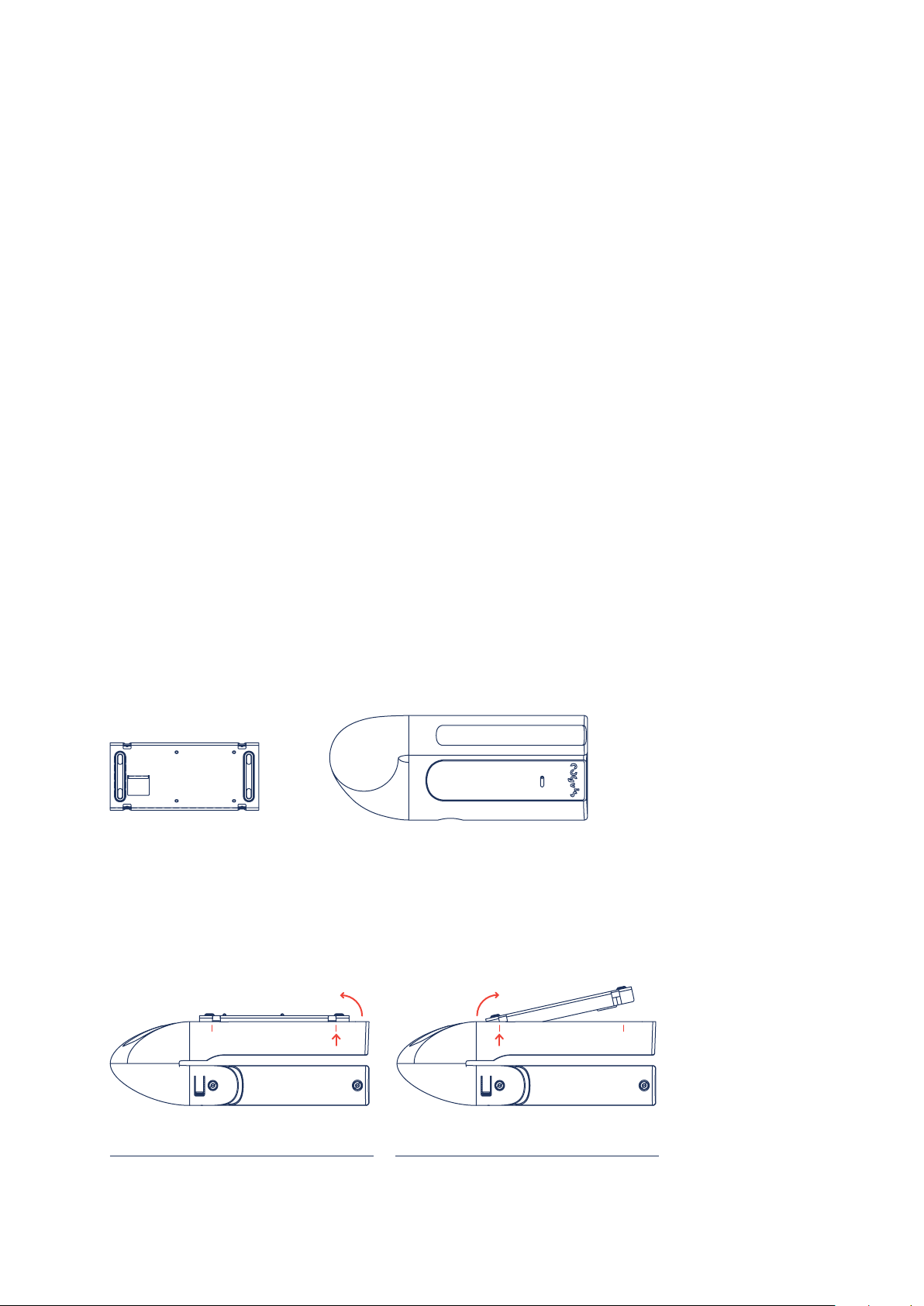
The fearless sensor consists of 2 parts: the metal base part with the already
mounted board (evaluation unit) and the white plastic sensor housing.
Metal base part Plastic sensor housing
The sensor housing is connected to the base unit through 4 clamps. Both parts
can be released from each other by slight pressure from the outside (along the
lower edge of the sensor unit in the area of the clamps). Please note the following
illustration:
Step 1: Press on both sides of the outer edge of the
unit in the area of the clamps and gently push the
base out on one side.
Step 2: If the first side is released, apply the same
principle to the second side and remove the base
completely from the housing.
Page 3 of 12
Page 4

3. Positioning of the system
At the beginning of the installation, you need to find the correct position for your
3D sensor in the room. Please note that the sensor can be easily adjusted in two
directions by turning it carefully.
fearless
Installation guide
The sensor can be adjusted accordingly by
carefully turning the front panel.
To rotate the entire sensor part, gently pull it out
of its anchorage, turn it to the correct position and
release it again until it clicks into place.
The front part can be turned in both directions.
The entire sensor part can also be turned in both
directions.
Identify the main area that should be covered. This is the free area with a
particularly high risk of falling. The sensor can be mounted on the wall or on
the ceiling. We recommend mounting the sensor on the ceiling, as the sensor
orientation is more flexible.
Page 4 of 12
Page 5
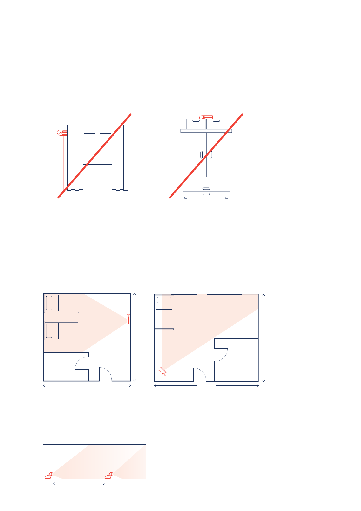
Please make sure that the sensor is not covered by objects (e.g. curtains,
lampshades, boxes in front of the bed etc.) and has a maximum range of approx.
7 meters. If possible, the sensor should be placed on the opposite side of the
windows.
fearless
Installation guide
Make sure that you do NOT cover the 3D sensor
with the curtain.
Make sure that you do NOT mount the 3D sensor
above a cabinet in such a way that the visibility of
the sensor is restricted.
Sample illustrations for the sensor position
Sample illustrations for the sensor position The following example rooms will help
you to find the correct sensor position. The color-coded area represents the area
that the sensor covers approximately.
Window
5 meters
Bathroom
5 meters
Window
Window
Bathroom
6 meters
5 meters
This illustration shows a room where wall or ceiling
mounting is possible. The sensor is adjusted so
that both beds and the surrounding areas are in
sight.
7 meters
The second illustration shows a room in which
ceiling mounting is preferred. In this case, the
greatest possible coverage is guaranteed.
Illustration 3 shows an elongated room, such as a
corridor. In this case, the sensor should be mounted vertically on the wall.
Page 5 of 12
Page 6
4. Mounting
Make sure the sensor is not covered by curtains, plants, lampshades, boxes, etc.
For wall mounting, the sensor has to be positioned and aligned horizontally in
order to enable automatic calibration.
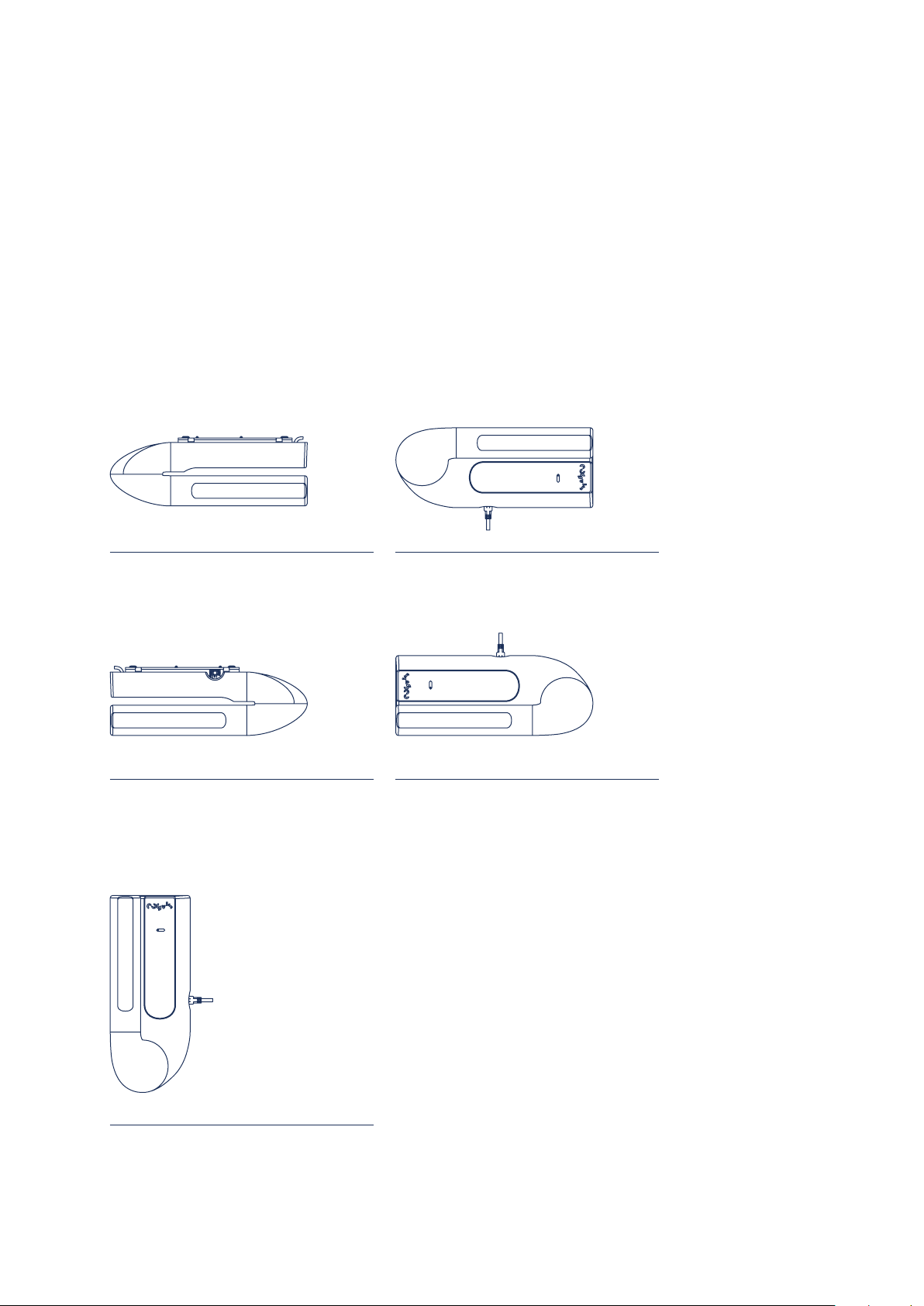
The following wall mounting positions are possible:
fearless
Installation guide
a) Standard ceiling mounting
c) Ceiling mounting 180-degrees rotation
(if required)
b) Standard wall mounting
d) Wall mounting 180-degree rotation
(if necessary)
Please note that in this case you must also adjust
the image „Initialization started“ online on the
platform under the view „Sensor“ accordingly!
Otherwise there will be problems during
calibration (see page 11).
e) 90-degree rotation (if necessary)
Please note that you have to adjust the view under
„Initialization started“ accordingly!
Page 6 of 12
Page 7
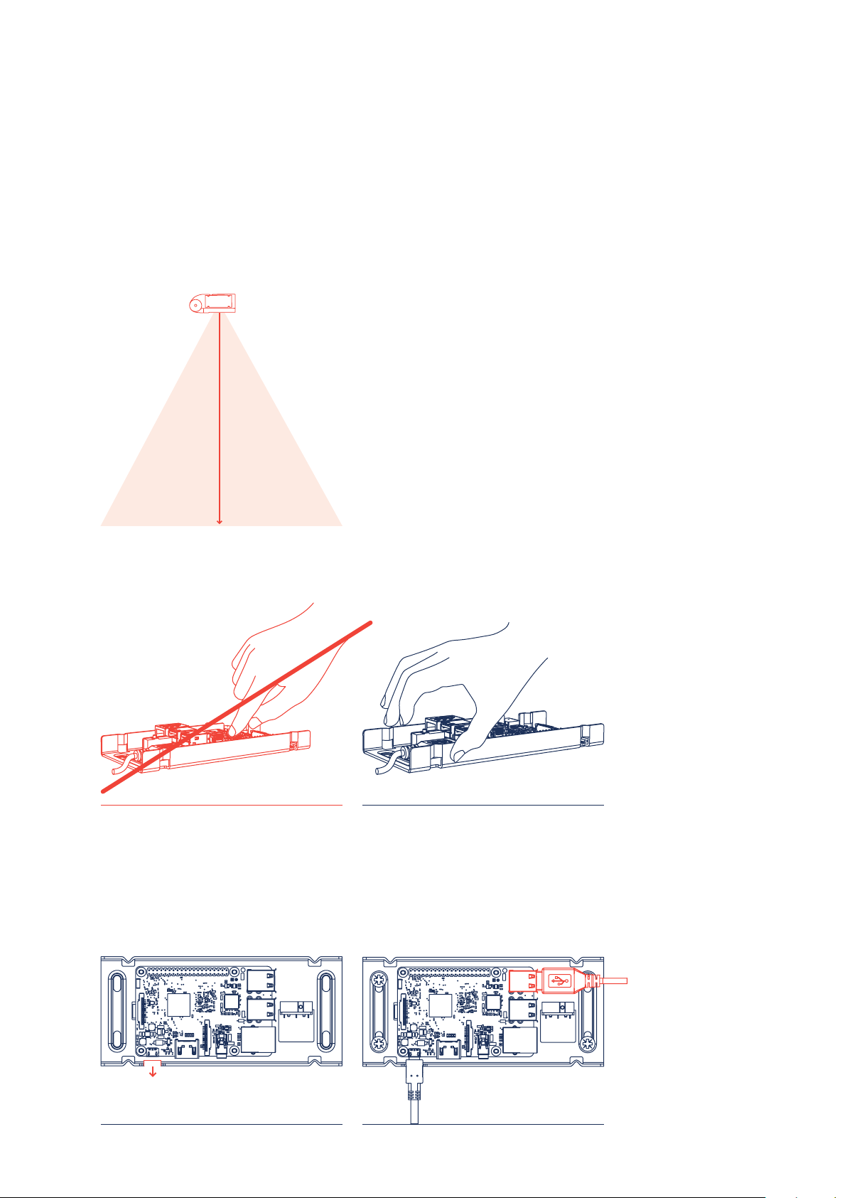
The sensor should be mounted at a height of approx. 2.5 meters (wall mounting)
in the middle of the wall. Ceiling mounting is recommended for room heights up
to approx. 3 meters. The sensor can be positioned either in the middle or in the
corner. The sensor should point to the area in front of the bed. In the best case,
the sensor is positioned opposite the windows.
Please note that the sensor has
a maximum range of 7 meters.
Maximum
range:
7 meters
fearless
Installation guide
When mounting, please use the four included dowels and screws.
Never touch the board, only the metal plate.
Never touch the board! Only touch the metal plate!
Note that the cut-out for power
supply (Micro-USB) looks towards the
electrical socket (usually downwards).
Once you have mounted the metal
plate on the wall, plug the USB cable
into one of the two exposed USB
openings on the board.
cut-out for socket outlet
exposed USB ports
Page 7 of 12
Page 8
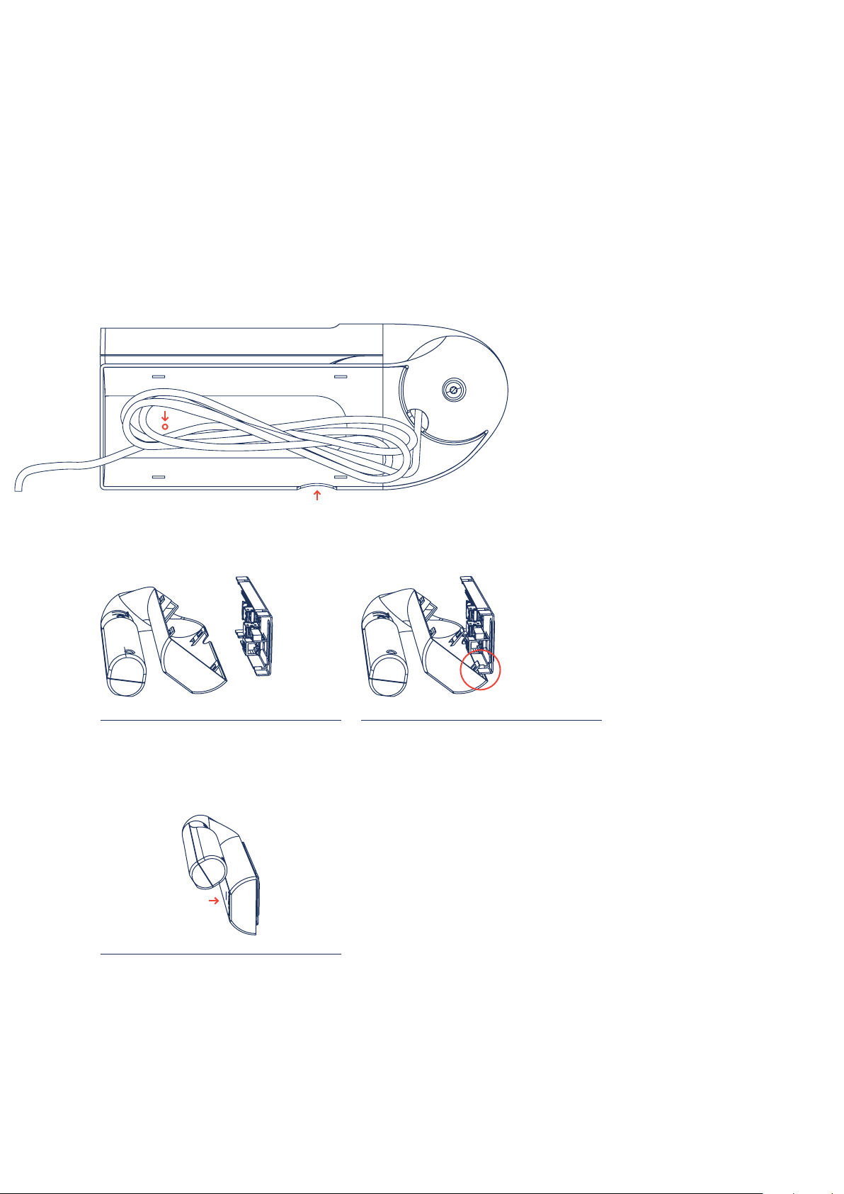
Now carefully stow the cable in the housing. Make sure that the push-button
(on the inside of the housing) is free (not covered by the black cable).
Also make sure that you close the housing in such a way that the power
connection of the board is at the corresponding opening of the housing.
fearless
Installation guide
Now mount the housing onto the metal plate as follows:
Step 1:
Place the housing from bottom to top. Make sure
that the metal plate is outside the clamp of the
housing.
Step 2:
Hook the clamps from the housing to the metal
plate. Press the casing together to connect it to
the metal plate at the top edge.
Step 3:
Now press the housing onto the metal plate until it
clicks into place.
Now continue with software setup.
Page 8 of 12
Page 9
5. Software setup
After you have mounted and aligned your fearless device at the appropriate
position, you can start with the software setup. Make sure to configure no more
than 1 device at the same time, the housing is already mounted on the wall and
the sensor is roughly aligned. Please have the serial number of your device (to be
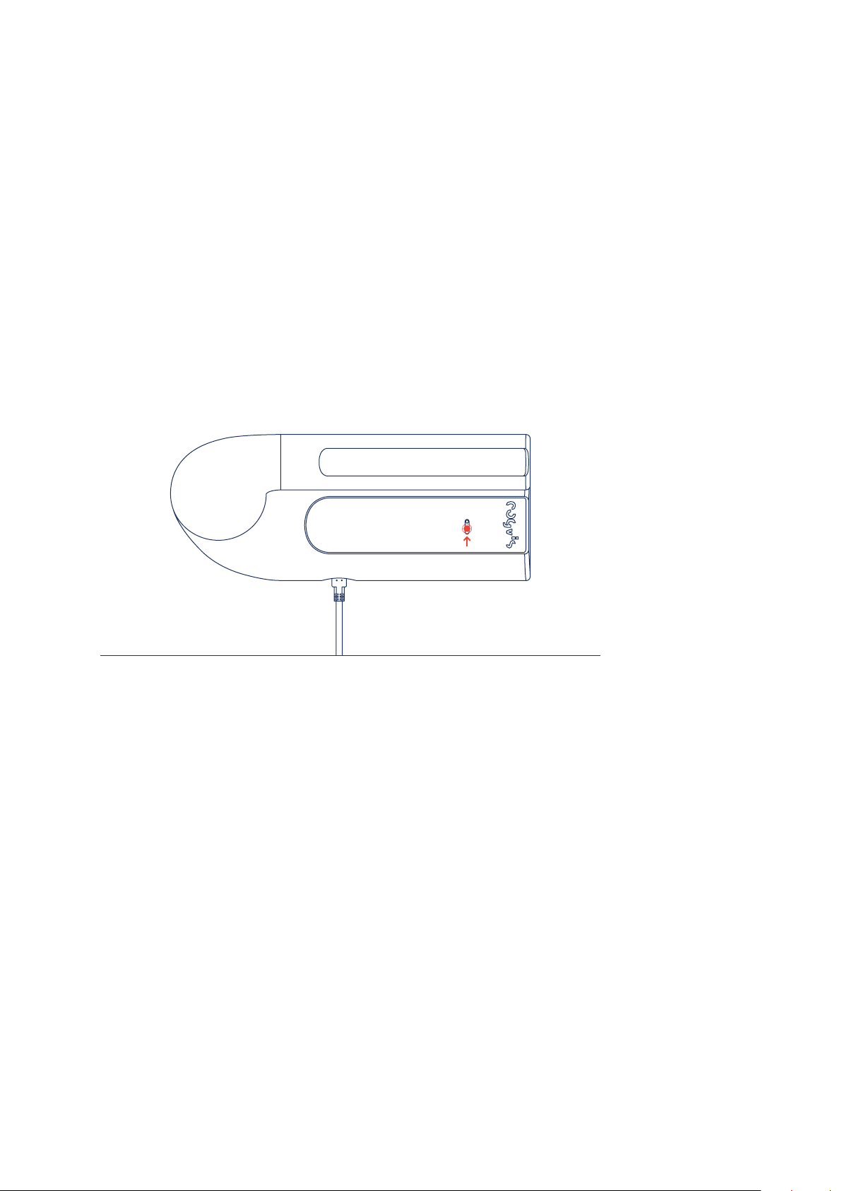
found on the underside of the packaging) ready for further steps. If problems occur
during setup, please press the button on the upper side of the white housing for
approx. 8 seconds (see illustration) and then restart the setup procedure.
fearless
Installation guide
Setup problems: Press the button for 8 seconds.
Step 1: Start setup
Start the device by connecting the power cable and the power supply to the power
outlet.
Now activate the WiFi of your smartphone or laptop and connect to the
corresponding WiFi network: fearlessAP-XXXXXXXX. (it can take up to 2 minutes
to display the corresponding network) The last 6 characters are different from
device to device. The password is fearless.
Newer versions of Android devices require explicit confirmation that you want to
connect to a WiFi without an Internet connection. Please confirm this query to
keep the network.
Page 9 of 12
Page 10

Step 2: WiFi setup
Open the following URL in your web browser (Chrome, Internet Explorer, etc.):
http://fearless.setup or http://192.168.8.1
If it is not possible to access the web browser, please try connecting to the
WiFi again. Then click on „Select network“, select your network and enter the
appropriate WiFi password. If your wireless network is not visible/selectable, the
signal is too weak to guarantee reliable data transmission. In this case, please use
a WiFi amplifier.
Now enter the serial number of your device. These can be found on the bottom of
the packaging (S/N: XX-XX-XX-XX-XX). Please wait 2-3 minutes and then check the
status of your device.
If there are any problems, make sure that you have entered your WiFi password
correctly and start again with step 1.
fearless
Installation guide
Note:
To connect your fearless system to a new WLAN, press the button on the housing for 1-3 seconds. Then,
as described in step 1, search for the appropriate wireless network and repeat the following steps.
Step 3: Check status
Now please check the status of your device. To do so, click on „Check status“ or
enter the following address in your web browser: https://web.fearless-system.com
If the device is not „online“ after 5 minutes, please set up the device again, starting
with step 1.
Explanation of the status on the platform:
Initializing: The device is preparing for start-up.
Active: Sensor is in operation.
Inactive: Operation was stopped / fall detection paused.
Online: Device is connected to the Internet.
Offline: Device is not connected to the Internet or the power supply.
Calibration error: The ground floor cannot be detected by the sensor. Please
check the position and orientation of the sensor.
Visibility error: The visibility of the sensor is limited. Please make sure that the view
of the sensor is not occluded by objects. (see page 5)
Sensor error/unexpected error: Please contact the cogvis support team
(+43 1 236 058 0 or [email protected]).
Page 10 of 12
Page 11
Step 4: Alignment and Calibration
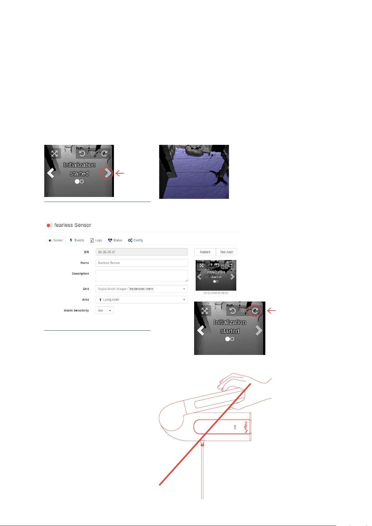
Calibration is automatic. To display the calibration view, click on the right arrow
in the „Initialization started“ image view. The floor is displayed as a blue area. If
problems occur, check the position of the sensor, realign it if necessary and click
on „Restart“ on the platform. Now check the image according to step 4.
Calibration visualization
fearless
Installation guide
Change of the sensor image on the platform,
if necessary, under „Initialization started“
(see page 6)
Step 5: Operation
If the setup and calibration were
successful, the position of the sensor
should NOT be changed any more.
If a change of position is necessary,
realign the sensor, then click on
„Restart“ on the platform and check
the calibration/image view according
to step 4.
Page 11 of 12
Page 12

6. Connection to existing call systems
This step becomes interesting for you if you want to connect to an existing alarm or
emergency call sys-tem. The integration into the call system is very uncomplicated:
fearless works with a radio-based solution from ELDAT, the transmitter is already
directly integrated into the fearless system. The RCL07 module is required as
receiver (http://eldat-en.fearless-system.com). If you already have some in use,
fearless can be connected directly to them. If you require appropriate modules incl.
connection cable, you are welcome to order them from us.
To connect the system to the existing call system, please consider the following
brief instructions:
1.) Trigger a test alarm on the fearless platform. To facilitate pairing, several test
alarms are now sent within 30 seconds.
2.) Briefly (< 1.6 seconds) press the programming button R. The receiver is now
ready to learn, the LED of the corresponding channel flashes.
3.) As soon as the pairing is successful and the system is ready for use, the LED
lights up briefly.
4.) If you want to test the functionality, you can trigger further test alarms at any
time.
fearless
Installation guide
We wish you much joy with fearless!
cogvis software und consulting GmbH
Wiedner Hauptstraße 17/1/3a
1040 Vienna
Austria
T +43 1 236 058 013
[email protected]
cogvis.at
Page 12 of 12
 Loading...