

Page 1
Owner’s Manual
Revision 1.0
Copyright 2014 Cognisys, Inc.
1
Page 2

Table of Contents
1. SAFETY INSTRUCTIONS ............................................................................................................................... 7
2. GETTING STARTED ..................................................................................................................................... 7
2.1 CLEANING AND CARE ......................................................................................................................................... 8
2.1.1 Cleaning ................................................................................................................................................... 8
2.1.2 Care and storage ...................................................................................................................................... 8
2.2 THE STACKSHOT 3X CONTROLLER ........................................................................................................................ 9
2.3 MOTORIZED GEAR........................................................................................................................................... 10
2.3.1 StackShot Macro-rail ............................................................................................................................. 10
2.3.2 Rotary Table ........................................................................................................................................... 10
2.3.3 Pan/Tilt Rotary System .......................................................................................................................... 11
2.4 CONNECTING RAILS/ROTARY SYSTEMS/SLIDERS .................................................................................................... 11
2.5 CAMERA CONNECTION ..................................................................................................................................... 12
2.6 GETTING FAMILIAR WITH STACKSHOT 3X ............................................................................................................. 12
3. BASIC NAVIGATION ................................................................................................................................... 14
3.1 COMMON ICONS ............................................................................................................................................. 14
3.2 COMMON SCREENS ......................................................................................................................................... 16
3.2.1 Distance Entry ........................................................................................................................................ 16
3.2.2 Time Entry .............................................................................................................................................. 17
3.2.3 Character Entry ...................................................................................................................................... 18
4. CHANGING OPERATING MODES ................................................................................................................ 18
5. FOCUS STACKING ...................................................................................................................................... 21
5.1 STACKING: CHECKLIST ..................................................................................................................................... 22
5.1 STACKING: SINGLE AXIS .......................................................................................................................................... 22
5.1.1 Mode: Automatic Step ........................................................................................................................... 23
5.1.2 Mode: Automatic Distance .................................................................................................................... 27
5.1.3 Mode: Total Travel Distance .................................................................................................................. 29
5.1.4 Mode: Distance per Step ........................................................................................................................ 31
5.1.5 Mode: Manual ....................................................................................................................................... 31
5.1.6 Mode: Continuous Movement ............................................................................................................... 33
5.1.7 Mode: Auto/Manual Advance ............................................................................................................... 33
5.1.8 Mode: Auto-Rotary ................................................................................................................................ 34
5.1.9 Mode: Rotary ......................................................................................................................................... 35
5.2 STACKING: X-R – STACK/ROTATE ...................................................................................................................... 36
5.2.1 Stack/Rotate Main Screen ..................................................................................................................... 36
5.2.2 Adjusting/Setting the X-axis................................................................................................................... 36
5.2.3 Adjusting/Setting the rotary position .................................................................................................... 38
5.2.4 Starting the Stack/Rotate Stack ............................................................................................................. 40
5.3 STACKING: X-Y SCANNING ............................................................................................................................... 41
5.3.1 Setting up the X or Y-axis ....................................................................................................................... 41
2
Page 3

5.3.2 Starting the X-Y Scan .............................................................................................................................. 43
5.4 STACKING: X-Y-Z SCANNING/STACKING .............................................................................................................. 45
5.5 STACKING: X-R-Z STACK/ROTATE/MOVE ........................................................................................................... 45
6. PANORAMIC ............................................................................................................................................. 46
6.1 PANORAMIC: INITIAL SETUP .............................................................................................................................. 46
6.1.1 Camera Settings ..................................................................................................................................... 46
6.1.2 Setting the aspect ratio .......................................................................................................................... 47
6.1.3 Setting the overlap ................................................................................................................................. 48
6.1.4 Setting the field of view ......................................................................................................................... 48
6.1.5 Checklist ................................................................................................................................................. 50
6.2 PANORAMIC: SINGLE AXIS ................................................................................................................................ 50
6.3 PANORAMIC: 360 ........................................................................................................................................... 52
6.4 PANORAMIC: MULTI-ROW ............................................................................................................................... 52
7. MOTION CONTROL ................................................................................................................................... 57
7.1 MOTION CONTROL: INITIAL SETUP ..................................................................................................................... 58
7.1.1 Camera Settings ..................................................................................................................................... 58
7.1.2 Checklist ................................................................................................................................................. 59
7.2 MOTION HOME SCREEN ................................................................................................................................... 59
7.3 MOTION HELPER............................................................................................................................................. 60
7.3.1 Video: Continuous .................................................................................................................................. 60
7.3.2 Shoot-Move-Shoot ................................................................................................................................. 66
7.4 CHANGING AXES ............................................................................................................................................. 69
7.5 VELOCITY CURVE ............................................................................................................................................. 69
7.6 TIME SETTINGS ............................................................................................................................................... 70
7.6.1 Lead-In ................................................................................................................................................... 71
7.6.2 Lead-Out ................................................................................................................................................ 71
7.6.3 Shutter Output Settings ......................................................................................................................... 71
7.6.4 Settle Time (SMS Only) ........................................................................................................................... 71
7.6.5 Video Duration (SMS Only) .................................................................................................................... 72
7.6.6 Video FPS (SMS Only) ............................................................................................................................. 72
7.7 ZERO ALL ....................................................................................................................................................... 72
7.8 GOTO ZERO ALL .............................................................................................................................................. 72
7.9 START (AND PREVIEW) ..................................................................................................................................... 73
7.10 ABORT SCREEN – SHOOT-MOVE-SHOOT ONLY ..................................................................................................... 73
7.11 EDIT AXIS ...................................................................................................................................................... 74
7.11.1 Rotary / Rail / Slider .......................................................................................................................... 75
7.11.2 Move to… ........................................................................................................................................... 76
7.11.3 Add Key frame ................................................................................................................................... 77
7.11.4 Edit Key frame ................................................................................................................................... 78
7.12 DRAGON FRAME DFMOCO ............................................................................................................................... 81
7.12.1 Dragon Frame connecting to StackShot 3X ....................................................................................... 82
7.12.2 Configuring the axes .......................................................................................................................... 83
8. SETTINGS .................................................................................................................................................. 87
8.1 GLOBAL MODE ............................................................................................................................................... 87
3
Page 4

8.2 AXIS SETTINGS ................................................................................................................................................ 87
8.3 LOAD/SAVE SETTINGS ...................................................................................................................................... 87
8.3.1 Save Settings .......................................................................................................................................... 88
8.3.2 Load Settings .......................................................................................................................................... 89
8.3.3 Load Factory Defaults ............................................................................................................................ 89
8.4 SHUTTER BUTTON ........................................................................................................................................... 89
8.5 SHUTTER OUTPUT SETTINGS .............................................................................................................................. 90
8.5.1 Pics Per Move ......................................................................................................................................... 90
8.5.2 Final Off Time ......................................................................................................................................... 91
8.5.3 Shutter I/O ............................................................................................................................................. 91
8.5.4 Pre-Trigger Delay ................................................................................................................................... 92
8.5.5 Shutter On/Off Time 1 ............................................................................................................................ 92
8.5.6 Shutter On/Off Time 2+ .......................................................................................................................... 93
8.6 TIME LAPSE .................................................................................................................................................... 93
8.7 LCD BRIGHTNESS ............................................................................................................................................ 94
8.8 BACKLASH CALIBRATION ................................................................................................................................... 94
8.9 AXIS LINKING (FOCUS STACKING ONLY) ............................................................................................................... 96
8.10 WIRELESS CONFIG ........................................................................................................................................... 96
8.10.1 Wireless Mode ................................................................................................................................... 96
8.10.2 Scan for network................................................................................................................................ 97
8.10.3 Saved Connections ............................................................................................................................. 98
8.10.4 Regulatory Domain ............................................................................................................................ 99
8.10.5 AP Security ....................................................................................................................................... 100
8.11 VIEW LOG .................................................................................................................................................... 100
8.12 ASPECT RATIO .............................................................................................................................................. 100
8.13 PANORAMIC OVERLAP .................................................................................................................................... 100
8.14 MOTOR POWER SAVE .................................................................................................................................... 101
8.15 LCD POWER SAVE ......................................................................................................................................... 101
8.16 HAPTIC FEEDBACK ......................................................................................................................................... 101
9. AXIS SETTINGS ........................................................................................................................................ 102
9.1 AXIS TYPE .................................................................................................................................................... 102
9.2 SETTLE TIME ................................................................................................................................................ 102
9.3 STACK SPEED ................................................................................................................................................ 103
9.4 FWD/BACK SPEED ......................................................................................................................................... 103
9.5 RAMP TIME ................................................................................................................................................. 103
9.6 TORQUE ...................................................................................................................................................... 103
9.7 HIGH-PRECISION ........................................................................................................................................... 103
9.8 AUTO-RETURN ............................................................................................................................................. 103
9.9 POLARITY ..................................................................................................................................................... 104
9.10 SHUTTER ..................................................................................................................................................... 104
9.11 RAIL DIST/REV ............................................................................................................................................. 104
9.12 RAIL BACKLASH ............................................................................................................................................. 104
9.13 ROTARY SPEED ............................................................................................................................................. 104
9.14 ROTARY GEAR RATIO ..................................................................................................................................... 105
9.15 ROTARY BACKLASH ........................................................................................................................................ 105
9.16 ROTARY SMART RETURN ................................................................................................................................ 105
4
Page 5

9.17 SLIDER DISTANCE/REV ................................................................................................................................... 105
9.18 SLIDER BACKLASH .......................................................................................................................................... 105
9.19 SLIDER SPEED ............................................................................................................................................... 105
9.20 SLIDER RAMP TIME ........................................................................................................................................ 106
10. EXAMPLES .......................................................................................................................................... 107
10.1 FOCUS STACKING – SINGLE AXIS ...................................................................................................................... 107
10.2 FOCUS STACKING – VIRTUAL OBJECTS ............................................................................................................... 113
10.3 MOTION – SHOOT-MOVE-SHOOT .................................................................................................................... 118
11. INSTALLING THE REFLASH SOFTWARE (OPTIONAL) .............................................................................. 127
11.1 WINDOWS INSTALLATION ............................................................................................................................... 127
11.2 OS X INSTALLATION ....................................................................................................................................... 127
12. TROUBLESHOOTING ............................................................................................................................ 129
13. SPECIFICATIONS .................................................................................................................................. 131
14. WARRANTY ........................................................................................................................................ 132
15. GLOSSARY .......................................................................................................................................... 133
16. REVISION HISTORY .............................................................................................................................. 134
5
Page 6

Table of Figures
Figure 1 – StackShot 3X Controller ............................................................................................................... 9
Figure 2 - Steps Vs. Pictures ........................................................................................................................ 24
Figure 3 - Automatic Step Mode ................................................................................................................. 26
Figure 4 - Automatic Distance Mode .......................................................................................................... 28
Figure 5 - Total Distance Mode ................................................................................................................... 30
Figure 6 - Manual Mode .............................................................................................................................. 32
Figure 7 - Continuous Mode ....................................................................................................................... 33
6
Page 7
1. Safety Instructions
WARNING indicates a potentially hazardous situation which, if not avoided, could result in death
or serious injury.
Follow all CAUTION notices to reduce the risk of personal injury, prevent damage to the
StackShot 3X controller, accessories, and devices (computers, cameras, flashes, etc). Failure to
follow all CAUTION notices may void your warranty. CAUTION may also indicate a potentially
hazardous situation which, if not avoided, may result in personal injury.
The safety alert symbol precedes a general CAUTION or WARNING statement.
The electrical hazard symbol precedes an electric shock hazard CAUTION or WARNING
statement.
CAUTION: Only use the AD/DC power adapter (cube) that was included with your StackShot 3X.
Use of other power adapters may damage the controller and/or attached equipment.
CAUTION: The StackShot 3X controller moves your camera equipment and/or the subject you
are photographing. Motion control gives you incredible flexibility for your photography.
However, this motion can cause a shift in weight potentially causing injury or damage if the
equipment is not properly secured and/or balanced. It is your responsibility as a user to ensure
the equipment will remain properly secured and safe. Additionally, incorrect settings or misuse
of the controller could potentially damage your equipment. Cognisys, Inc. will not be held liable
for damage to your equipment. To stop the motors from moving at any point touch the display
and/or remove power from the controller.
2. Getting Started
The latest version of this manual is available at http://www.cognisys-inc.com
The graphics included in this manual may not be identical to the software that you are running.
Improvements and adjustments to the software may happen prior to an updated version of the
manual. You’ll see several screen-shots in this manual. They are actual screen-shots from the
controller and not “artist renderings” made to look pretty. StackShot 3X really is that beautiful.
Not big on reading manuals? (What? No thumbs-up? We worked hard on this you know!) We
have a few real world walk-throughs in the “10 - Examples” section. You can always come back
to the technical details if you get stuck.
.
7
Page 8

2.1 Cleaning and Care
We want your StackShot 3X to last – so here are some brief steps to keep your controller
happy!
2.1.1 Cleaning
For cleaning the display first use a dry micro-fiber cloth. If that doesn’t remove debris or
smudges you can use a slightly dampened (not wet) micro-fiber cloth. It must not be wet
enough to cause water to leak around the edge of the display. Do not spray water directly
onto the controller. Any liquid that goes into the controller may cause an electrical failure
of the device. Do not use a flammable liquid or cleaning agent on the controller – just a
micro-fiber cloth (dampened, only if needed).
2.1.2 Care and storage
StackShot 3X is a precision piece of electronics. It’s designed to handle normal wear and
tear but there are some things to avoid:
Do not get the unit wet.
Do not drop the unit (the display cover, much like a cell-phone, is made of glass)
Protect the unit’s display when packing up your gear. If a rotary table fights the
display on the controller – the rotary table will win.
8
Page 9
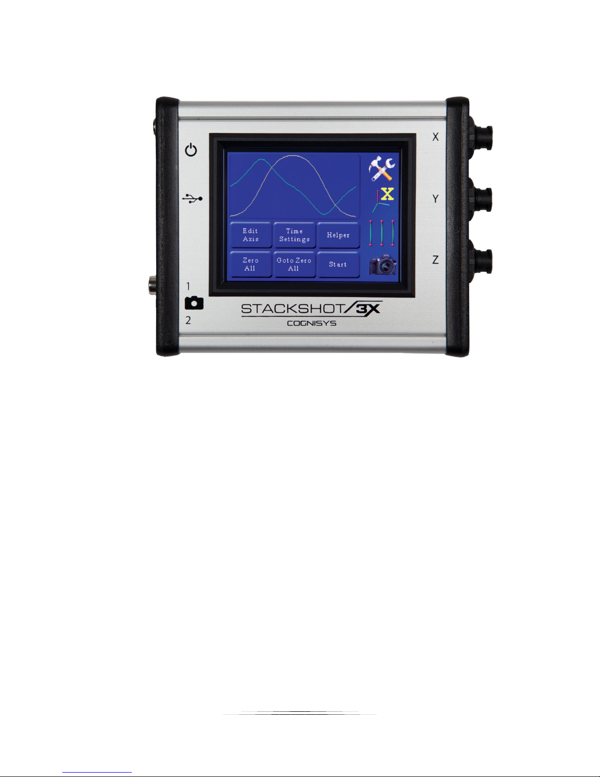
2.2 The StackShot 3X Controller
1
1
2
3
4
5
6
2
3
Figure 1 – StackShot 3X Controller
The left side of StackShot 3X has the following connectors/buttons from top to bottom:
1. DC power (2.1mm jack)
2. Power switch
3. LED power indicator
4. USB connector
5. Shutter output 1 – RCA connector (can also function as an input)
6. Shutter output 2 – 3.5mm connector
On the right side:
1. Motor X – Twist/lock connector
2. Motor Y – Twist/lock connector
3. Motor Z – Twist/lock connector
9
Page 10

2.3 Motorized Gear
You have an excellent StackShot 3X controller – chances are you’re going to want to attach it to
something equally as awesome. We have you covered! Here is a brief summary of the
accessories available.
2.3.1 StackShot Macro-rail
The StackShot macro-rail is ideal for focus-stacking. It provides precision down to 2um and is
available in two different sizes: 100mm (4 inches) or 200mm (8 inches) of travel. It is an
amazing tool for those serious about macro photography.
2.3.2 Rotary Table
The rotary table is perfect for rotating specimens for focus stacking as well as panning cameras
for beautiful time lapse or real-time motion effects.
10
Page 11

2.3.3 Pan/Tilt Rotary System
The Pan/Tilt rotary system includes two rotary tables. They can be used individually or
combined with the included brackets for full pan/tilt effects. This combination allows for gigapixel panoramas or full-blown motion control.
2.4 Connecting Rails/Rotary Systems/Sliders
The motor connectors are a twist/lock style connector. Simply align the arrow on the cable to
the top of the controller and insert the cable. If it does not fully seat, rotate the locking portion
of the cable counter-clockwise until it is fully seated. Once seated, turn the locking shroud
clockwise to lock it in place.
11
Page 12

2.5 Camera connection
Start
StackShot 3X supports two types of camera connections: an RCA-style connector and a 3.5mm
connector. The RCA connector is compatible with our existing shutter cables and switches. The
3.5mm connection provides the convenience of setting a programmable half-press focus time.
It also lets you use a wide variety of available shutter release cables with 3.5mm ends.
2.6 Getting Familiar with StackShot 3X
After you’ve plugged in the AC/DC adapter (or optional battery pack) into the StackShot 3X
controller, press and release the power button (just next to the DC power jack). The power LED
next to the plug will illuminate indicating the unit is powered. At this point the controller will
display “StackShot 3X” and at the bottom will show the current software version installed.
Not that you want to do this quite yet but if you want to turn off the StackShot controller, you
simply have to press and hold the power button for one second. “Why the press and hold” you
might ask? Field testing has shown that the more critical of a project you are working on the
more likely you are to accidentally bump the power button. “Can I just pull the power?” Yes,
you can – but if you have made changes to the settings they may not get stored.
Great! StackShot 3X is on and now… How do I tell it to do something? Touch the display!
You’ll feel the “haptic feedback” when you touch an icon (the display will vibrate slightly). There
are two styles of icons you can touch on. We’ll call the first a “button”. Think of it as a virtual
button that you would press or click on with a mouse. Here are some examples:
or…
The other type of user input that you can touch is a slider:
Sliders are used to adjust the current position of the motor. There is a twist though – the speed
control of the motor is dependent on the position of your finger. If you’re close to the center of
the slider, the motor will move slowly. If you are at the end of the slider, it will move
considerably faster. These sliders control both speed and direction. You’ll use them later to
12
Page 13

choose start and end points for focus stacks, where a panoramic should start or end, or adding
and editing key-frames for a motion profile you’ve selected. Don’t let that scare you. We’ll talk
more about the different operating modes in a little bit.
What is a “Shutter Output”? StackShot 3X can control up to two cameras. They could also be
other devices, like flashes or even other StackShot 3X controllers. You can adjust how long each
output is “on”, how many times it goes on, and the timing between each time it goes on. For
beginning users, you’re probably safe not changing the timing of these but just keep in mind you
can. Why might you want to do this? Mirror lockup is a perfect example. For this, you need to
press the shutter button twice. So in this case, the controller can activate the “shutter output”
twice. You can adjust the timing for how long to wait for the mirror vibration to stop. If you’re
using natural light, you might need a long exposure, so you may want to adjust the time after
the shutter is activated before the motor starts moving. All of that is adjustable and described
in more detail in section 8.5.
What is an “input”? One of the “Shutter Outputs” can be changed to an input. An input is
going to tell the StackShot 3X it needs to do something. It’s a way to tell the controller, “Okay,
now GO!”. This input could be a remote push-button, or even another StackShot controller. It’s
not something the average user would usually use but it is there in case you need it – we know
how creative you can be!
13
Page 14

3. Basic Navigation
X
In this section we’ll go into the basics of adjusting settings for StackShot 3X. If you find your
eyes glossing over with all the technical discussion you can always skip to the “10 - Examples”
section to start using StackShot 3X.
3.1 Common Icons
There are several icons you will see on the StackShot 3X screen. Their behavior is consistent
regardless of what mode you are in or what you are doing.
Take me home! It will always take you to the main screen for whatever mode you are currently
in. It doesn’t matter if you’re five screens deep and have found yourself somewhere spooky –
this will take you home in a hurry.
Change settings. Most importantly this is where you go to change what operating mode you’re
using. Beyond that you can adjust pretty much any setting -- from Wi-Fi settings to gear ratios.
or…
Change axis. If you’re using a mode that lets you adjust different behavior for each axis, this
will change which axis you are working with. The “X” indicates you’re working on the X-axis.
Move axes. If you touch this icon you will be able to adjust all three axes in one place. As
mentioned above, the speed and direction depends on where you put your finger. You can
slide up and down to adjust the move speed.
14
Page 15

Activate Camera. This will activate the camera output(s). You can adjust which output this
activates in section “8.4 - Settings”. The output will behave as configured in section “8.5 Shutter Output Settings”. When the outputs are active there will be a red-circle with the output
number shown on top of this camera icon.
Adjust position. This will allow you to control the position of the current axis. The further you
move along the slider the faster the motor will move. Above the center dot is forward, below is
backward.
Scroll up/down. This lets you scroll through all the settings. If there are more settings available,
you will see a scroll-bar on the right-hand side of the screen showing how far you are into the
list of settings.
Return to the previous menu. This will take you back just one screen. The “home” button will
take you all the way to the main screen.
15
Page 16
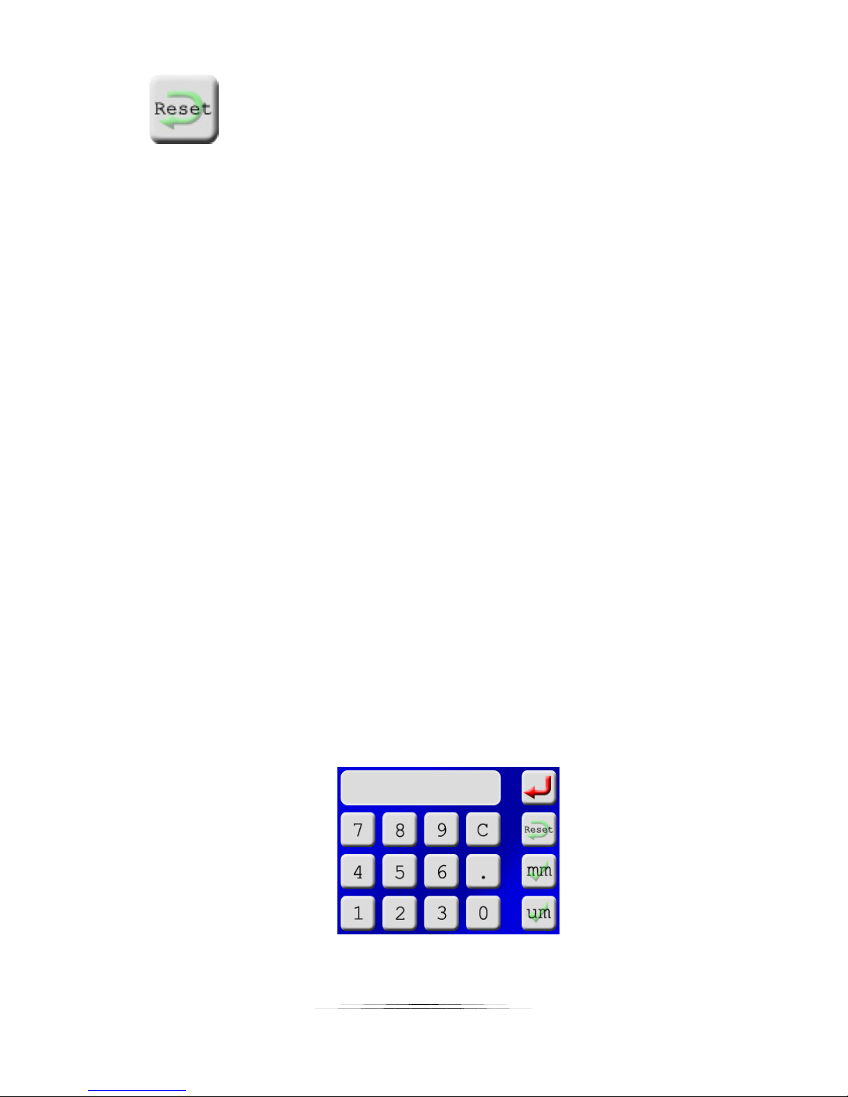
Reset this setting to the default. This is the “uh oh” button. Let’s say you accidentally changed
the shutter activation time to four hours but now don’t remember what a “safe” setting is. You
could always load the factory default settings for everything but that might be a bit extreme. If
you just want to change this specific setting back to the default touch the “Reset” button.
3.2 Common Screens
There are a few common screens used frequently to enter information for StackShot 3X. While
these screens don’t show it, there are some limits to what you’re allowed to enter – but they’re
pretty big. 10,000 shutter activations per motor move, maximum shutter activation time of 24
hours, etc… If you DO enter a value that is either too big or too small, the controller will nudge the
setting you entered to the nearest acceptable value.
3.2.1 Distance Entry
Distance is entered using a virtual numerical keypad. That is a fancy way of saying a “screen that
looks like the windows calculator”. There are two different distance units supported: Metric,
and degrees. Why aren’t inches supported? One main reason: Your camera and lens don’t
think in inches. Also, whether it is focus stacking or running a complex motion profile you
usually visually choose the start, end, and everything in-between. One occasion you need to
spell out a distance is for focus stacking, and it is related to your depth of field – which is likely
going to be spelled out in “mm” or “um”. Another would be the specific degrees of rotation.
All linear distances are entered in either “um” or “mm”. If you’re not familiar with metric:
um: A micrometer. A millionth of a meter. Very small – a human hair is on average 100um.
mm: A millimeter. A thousandth of a meter. Still pretty small – there is 25.4 mm in one
inch.
Here is an example of a linear distance-entry screen:
Here is the degree-entry screen:
16
Page 17
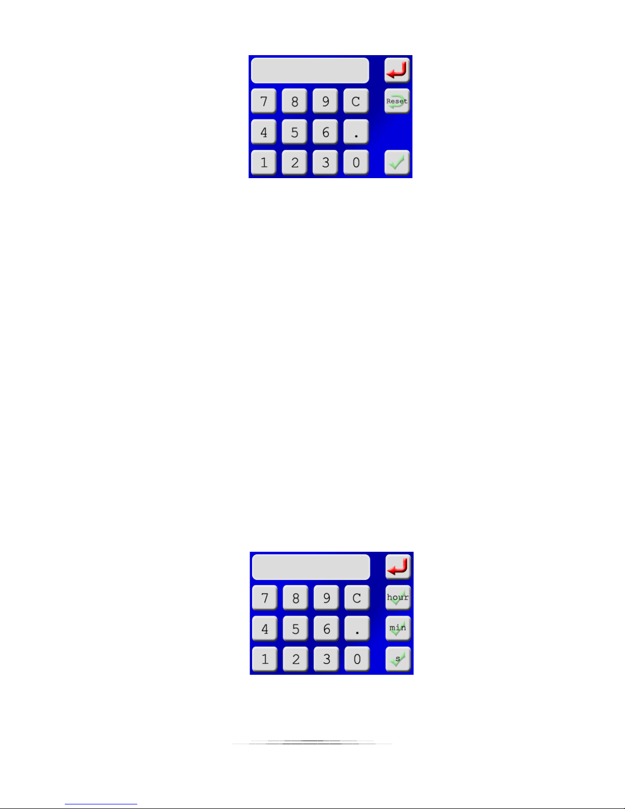
Notice how along the right side there is the return arrow (take me back without changing!), a
“Reset” which restores the factory setting, and then “mm” and “um” -- with a green check-mark
behind it. If you wanted to travel 12.5 mm, you would touch “1”, “2”, “.”, “5” and then “mm”.
Once you touch the “mm” it will save your setting and return you to the previous screen.
You’ll also see a “C” button, which works exactly like the clear function on a calculator. It will
clear what you have already entered and let you start over again.
3.2.2 Time Entry
The units of “time” will change depending on what you are modifying. If you’re adjusting the
shutter activation time, you’ll see “ms” listed as an option, but not hours. If you’re doing time
lapse, a millisecond doesn’t really make sense so you won’t see that – but you will see hours.
This is to try and minimize the amount of options and clutter you have to see. If you really
REALLY want to have a shutter output that is active for two hours (7200 seconds) or a time lapse
that lasts a few milliseconds, you can still do that – but you’ll have to use the units displayed on
the screen.
ms: Millisecond. A thousandth of a second. Fast!
s: Second. Not so fast.
min: Minute. Kind of slow.
hr: Hour. Slow.
Here is an example of a time-entry screen:
Similar to the “Distance Entry” screen, you also have the return, reset, clear, and accept (with
the green check marks).
17
Page 18

3.2.3 Character Entry
There are sometimes when you may need to enter characters, numbers, or symbols. Here are
two examples:
1. You can specifically name a stored setting (or profile) for what the current setup does – for
example using a 65mm lens at 2x magnification photographing a flies head labeled “65mm
2x fly”. That way next time you want to get back to frequently used settings it’s easily
identifiable.
2. Entering your WiFi/802.11 router password. Thankfully you’ll only have to do this once!
Here is the character entry screen:
The character entry screen is similar to the distance entry – just with a lot more options. The
first screen shown is all capital letters. In the upper-right corner there is the “return” (get me
out of here!), and in the bottom right “accept”. In the bottom left there is the “DEL” button,
which will delete your last entered character (backspace – but the abbreviation “BS” seemed
inappropriate). You’ll notice right above the “DEL” button is “abc”. Since all the letters on this
screen are capital letters, if you touch this button it will change to lower-case. Once in lowercase mode you’ll see it shows “123”. If you touch the “123” button you’ll be in number/symbol
mode. Pressing the ABC/abc/123 will cycle you through the three character entry screens.
4. Changing Operating Modes
An operating mode is just a way of telling StackShot 3X what you want to do – because it can do
a lot! There are three main categories for the operating mode:
1. Focus Stacking
2. Panoramic
3. Motion Control
Each of these modes has more specific applications beneath it.
18
Page 19
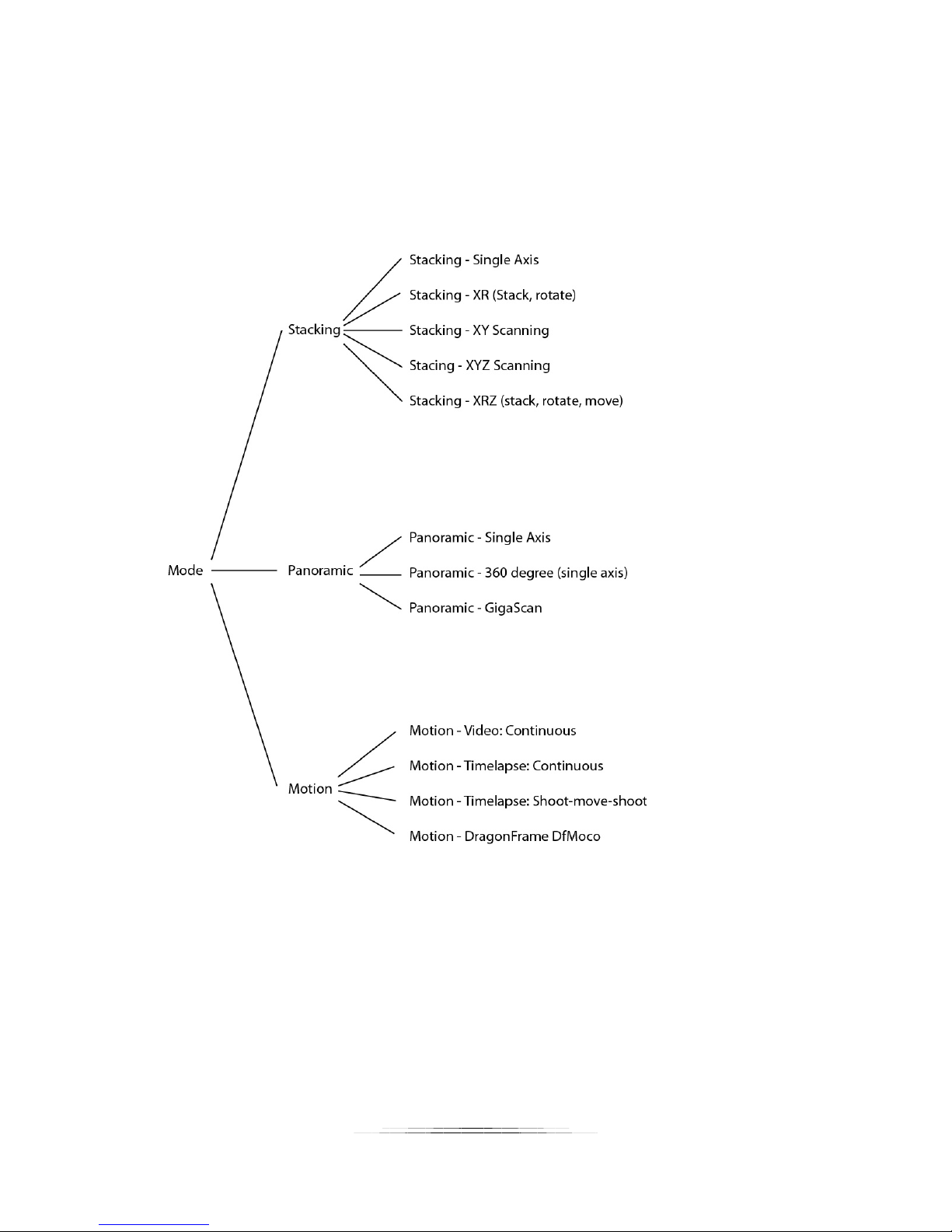
Here is an overview of the modes:
Focus stacking is (for our products) adjusting the position of a camera in precise steps moving
either toward or away from an object. Generally in macro-photography, the depth of field
(DOF) can be quite poor especially if the subject is close to the lens. By taking several different
images and then processing them using a focus stacking program (such as Zerene Stacker or
Helicon Focus), a greatly improved DOF single image can be generated. See section “5 - Focus
Stacking” for the available focus-stacking modes.
Panoramic refers to panning and/or tilting the camera with the intent to stitch together several
photos. This includes partial to full 360 degree pans, and even combining tilt for creating gigapixel images. See section “6 - Panoramic” for available panoramic modes.
The final category is Motion Control. While the previous two modes are indeed motion control,
this mode is tailored toward pan/tilt/slider applications. This could be time lapse shoot-moveshoot, continuous movement for video, or complex movement paths specified on a computer.
See section “7 - Motion Control” for the available motion control modes.
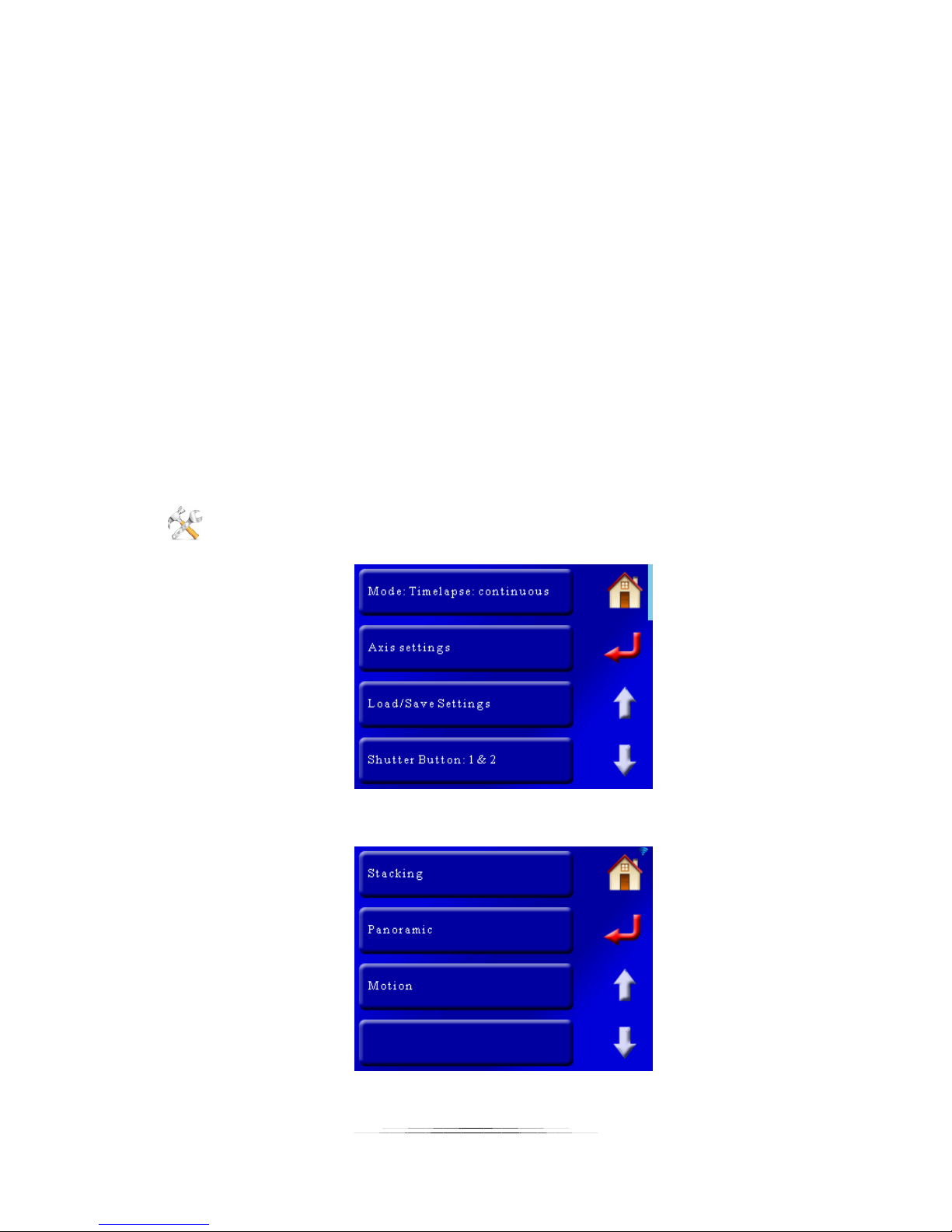
Changing the current operating mode is simple. You first start by clicking the “Settings” button
in the upper-right corner. The first button to appear is the mode you are currently in:
If you touch the top “Mode” button, it will bring up the category of different modes:
19
Page 20
From here you can choose what you would like to do with StackShot 3X. Touching one of the
three above buttons will bring up a list of modes specific to Stacking, Panoramic, or Motion
control.
Here is the full navigation of the different modes. The modes are discussed in more detail in
their specific chapter.
20
Page 21

5. Focus Stacking
With macro photography all too often pictures have a shallow depth of field (DOF). This is
where StackShot (and widely available focus-stacking software programs) shine. StackShot 3X
allows precise control over a camera’s position and is intended for use with macro photography.
It automates the process of taking several pictures in incremental steps. The subsequent images
are then processed by focus-stacking software to merge the shallow DOF images into a single
crisp and highly detailed picture. While this same process can be accomplished manually,
getting precise steps is difficult, time consuming, and frustrating. Decreasing the time spent
taking the images also allows you to focus-stack things that just wouldn’t cooperate or stay still
long enough. By combining a simple user-interface with behind-the-scenes flexibility, StackShot
3X is a necessity for any serious macro photographer.
CAUTION: Always keep your body, cables, and equipment clear of the rail while it is in motion.
Be aware of the environment you are operating in. The center of gravity will change as
StackShot 3X moves the camera. Moving the rail can potentially cause a tipping hazard. Be sure
that your tripod is secured and balanced properly to prevent damage to equipment. Monitor
your camera, lens, and other equipment at all times while the rail is moving to prevent damage
to your equipment. The motor cable may pose as a tripping hazard. Use caution.
Focus stacking has five different operating modes:
1. Single Axis
2. X-R – Stack/Rotate
3. X-Y Scanning/Stacking
4. X-Y-Z Scanning/Stacking
5. X-R-Z – Stack/Rotate/Move
In the next few sections we’ll go into the details of the focus stacking operation. If you’d like to
skip ahead and for a real-world walk-through example, see our single-axis example in section
“10.1 - Focus Stacking – Single Axis” and our “Virtual Object” example in section “10.2 - Focus
Stacking – Virtual Objects”.
21
Page 22
X
5.1 Stacking: Checklist
Here is a list of requirements/suggestions for focus stacking:
o Camera in manual mode
o Camera set to single-shot (not continuous)
o Lens in manual focus
o Image stabilization off
o Aperture set to your lenses sweet spot (Generally two stops down from the widest
aperture)
o Take one or two shots more in front of and behind of your subject than you think you
need (more data is better than not enough)
o Use the preview function and keep an eye on the framing (it’s easy to have the subject
go out of frame!). Live-view can be useful for this as well.
o If using a flash: Settle time + shutter time needs to be long enough for your flash to
recharge
o If using a flash: diffused lighting is critical
o If you are using continuous lighting use mirror up or live view function to minimize
vibration
5.1 Stacking: Single Axis
Single axis focus stacking is the traditional method of stacking. Only one axis is moved at a time.
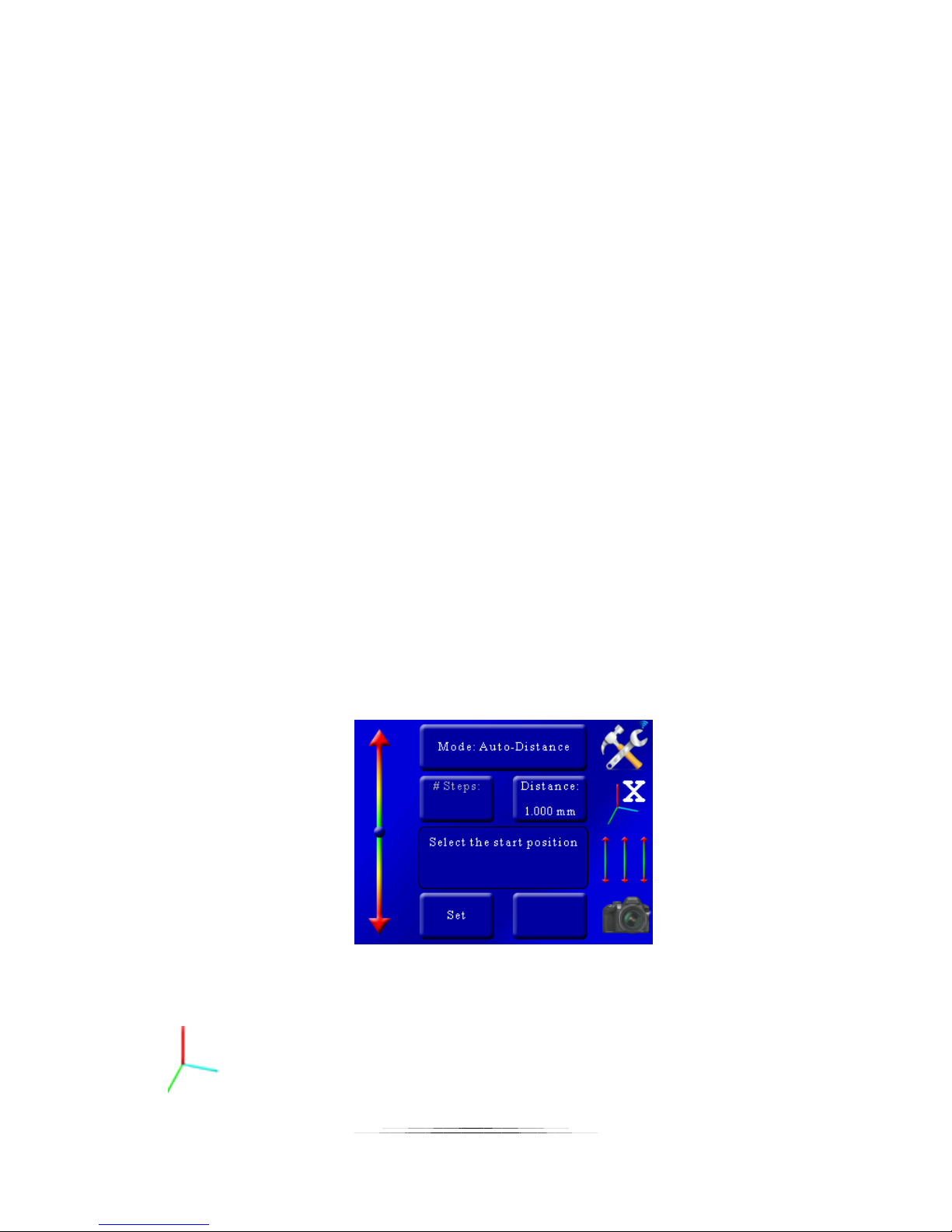
Once you enter single-axis mode, you are presented with the following screen:
You’ll notice the position slider on the left. You’ll see that the current axis is set to the X-axis as
indicated in by the axis icon:
22
Page 23
If you have the StackShot macro rail connected to another axis, you can touch this icon to
change through all the different axes.
You’ll see that the top button shows what type of stacking you will be using on this axis. Here
we will discuss the different stacking modes available:
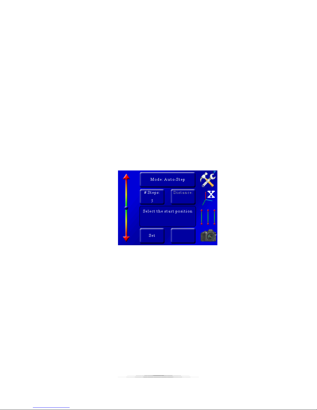
5.1.1 Mode: Automatic Step
Automatic Step mode (“Auto-Step”) simplifies the picture taking process. It allows the user to
determine the beginning and end position by using the position slider on the left, and also the
number of steps desired. There is no need to enter any distance – just choose the appropriate
start and end position that you desire.
5.1.1.1 Number of Steps
“# Steps” is the number of steps between the beginning and end position. The default number
of steps is 10. To adjust the number of steps simply touch the “# Steps” button and enter the
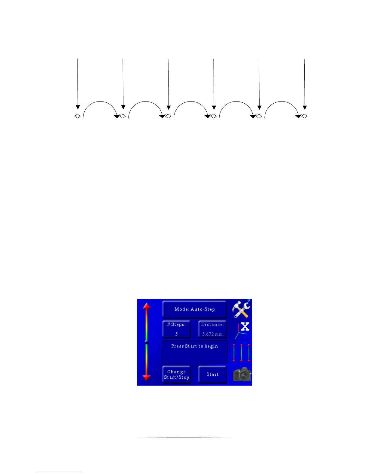
number of steps desired. StackShot 3X always takes a picture prior to moving the motor so the
total number of pictures taken will always be: “# Steps” + 1. See below:
As you can see in Figure 2 below, there are five steps (movements) of the rail. The first picture
starts prior to moving it, and the final picture occurs after the last step. Five steps -- six pictures.
23
Page 24
Pictures Taken
Step 1 Step 2 Step 3 Step 4 Step 5
Pic 1 Pic 2 Pic 3 Pic 4 Pic 5 Pic 6
Figure 2 - Steps Vs. Pictures
5.1.1.2 Selecting the Start/End Positions
In this mode you are first prompted to select the start position. Use the slider on the left to
move the rail to the starting position of the stack. Once the position is correct for your setup,
press the “Set” button.
You are then prompted to select the end position. Once again use the slider on the left to adjust
the position of the rail to the end position of the stack. Press the “Set” button to select the end.
5.1.1.3 Starting the Sequence
Once you have selected the start and end position you’ll see the following screen:
In this example the number of steps was set to five. You’ll notice that the “Distance” button is
grayed out because in Auto-Step mode you choose the number of steps, not the distance. It
does, however, show you the total distance the rail will travel.
24
Page 25

You are presented with two buttons at the bottom. If you press the “Change Start/Stop” button
you’ll be prompted for a new start and end positions. If you press the “Start” button the rail will
return to the beginning of the stack and begin the picture collection process. While the process
is running the status window will show which step is currently active and the time remaining for
the stack.
When the stack completes you’ll be given the option to change the start and end points or run
the stack again.
If you touch the screen any time during the stack it will stop the motor, abort the sequence, and
the display will show “Aborted” and give you the option to start the sequence again.
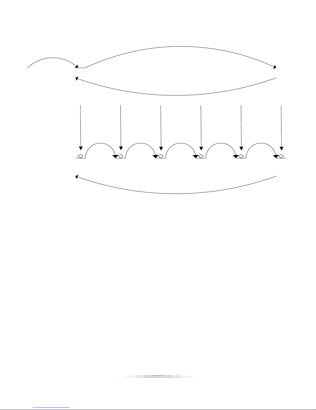
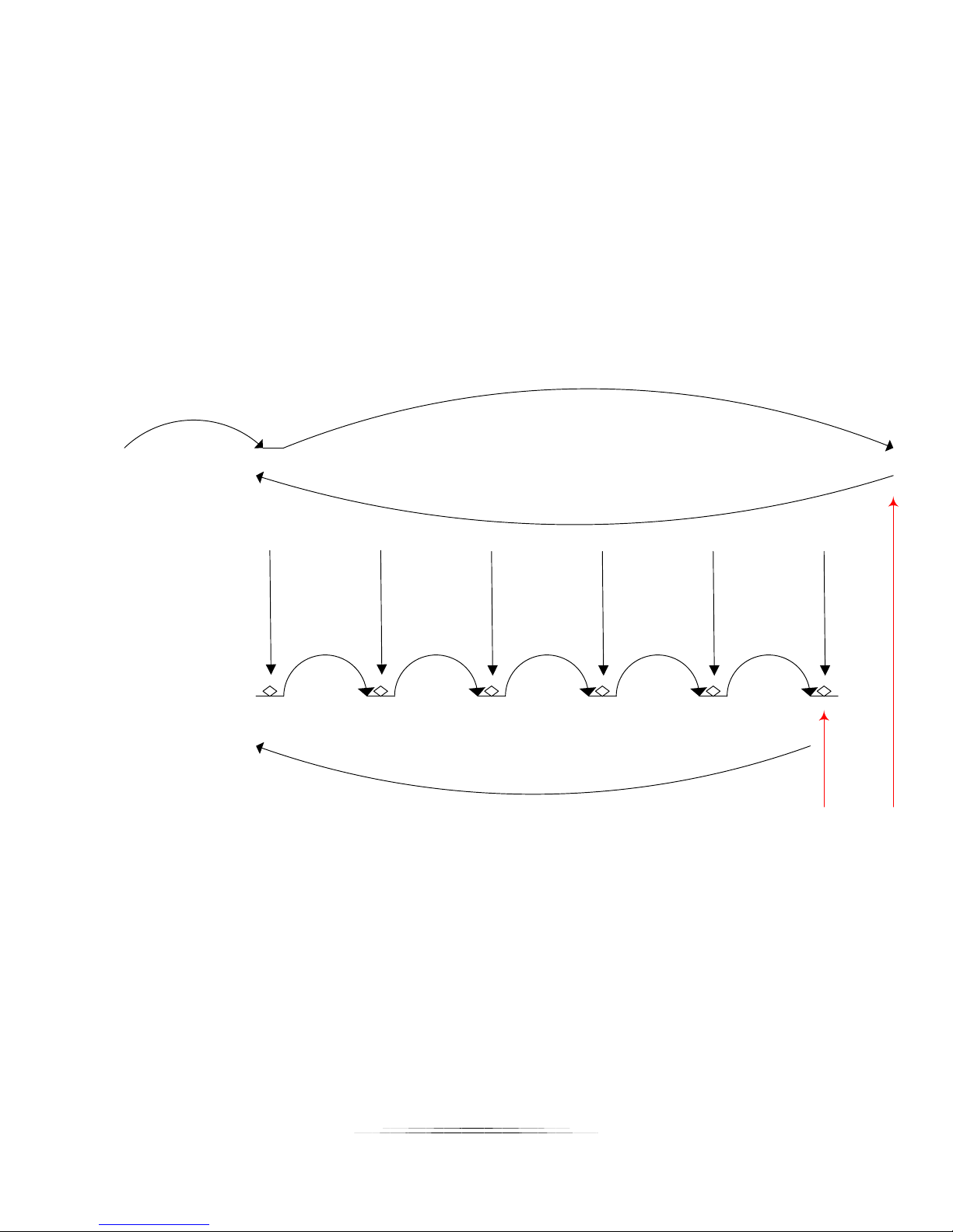
See Figure 3 below to demonstrate “Auto-Step” mode.
25
Page 26
Step 1 Step 2 Step 3 Step 4 Step 5
Pic 1 Pic 2 Pic 3 Pic 4 Pic 5 Pic 6
Step 1:
Manually move to
start position
Step 2:
Manually move to
end position
Step 3:
Automatically
returns to start
position
Step 4:
Automatically
takes pictures
Step 5:
Automatically
returns to start
position if “Auto
Return” is enabled.
Figure 3 - Automatic Step Mode
Note: If you adjust the rail position using the slider after the stack has completed, the rail will
move in the direction desired. If you then choose “Run Again”, it will use the current position
of the rail as the start rather than the original position. This allows adjustments to the starting
point without having to go through and choose a new start and end point for the stack.
26
Page 27
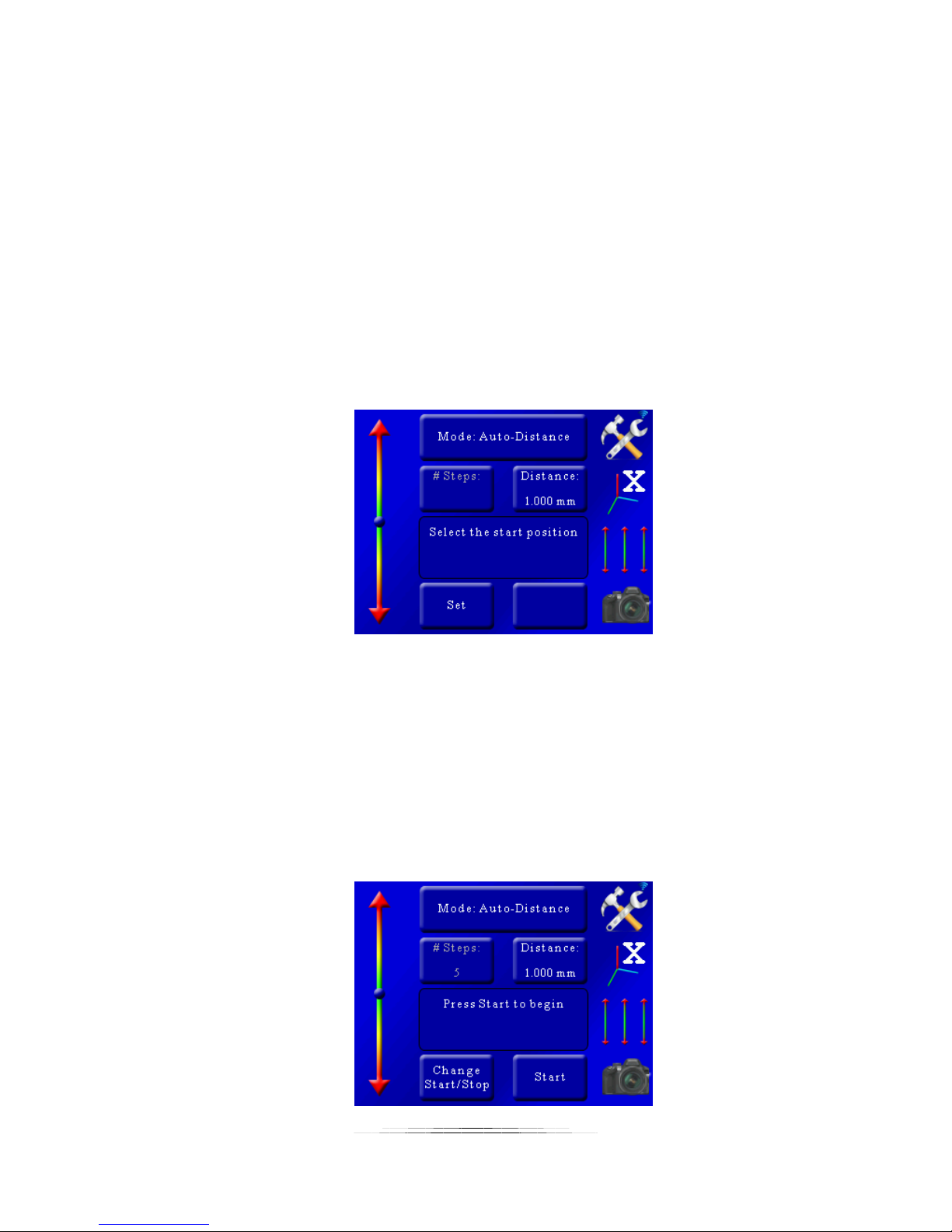
5.1.2 Mode: Automatic Distance
Automatic Distance mode (“Auto-Distance”) is very similar to “Automatic Step” mode. It allows
the user to determine the beginning and end position exactly like “Automatic Step” mode. The
only difference is that the user specifies the distance to travel for each step. StackShot 3X will
take a picture before first moving, and then at every distance interval specified. If the total
distance desired is not evenly divisible by the desired distance per step, StackShot will “round
down”, that is, it will not move the last partial distance. See Figure 4 below as an example.
5.1.2.1 Distance per Step
“Distance” is the distance the will move for every step. To adjust this distance press the
“Distance” button and enter the distance you would like the rail to move per step.
5.1.2.2 Selecting the Start/End Positions
Use the position slider on the left to find the appropriate beginning of the picture sequence.
Once happy with that position, press the “set” button. The status window will change to “Select
the end position”. Again, use the position slider on the left to choose the final position of the
sequence. Press the “set” button to confirm the end position.
5.1.2.3 Starting the Sequence
Once the final position has been selected, the status will change to “Press Start to begin”:
27
Page 28
Exactly like “Auto-Step” mode, you press the “Start” button to begin the sequence.
Move
200 um
Pic 1 Pic 2 Pic 3 Pic 4 Pic 5 Pic 6
Step 1:
Manually move to
start position
Step 2:
Manually move to
end position
Step 3:
Automatically
returns to start
position
Step 4:
Automatically
takes pictures
Step 5:
Automatically
returns to start
position if “Auto
Return” is enabled.
Move
200 um
Move
200 um
Move
200 um
Move
200 um
Distance not
travelled. The
end point is
not more than
0.2 mm away.
When the stack completes you’ll be given the option to change the start and end points or run
the stack again.
If you touch the screen any time during the stack it will stop the motor, abort the sequence, and
the display will show “Aborted” and give you the option to start the sequence again.
See Figure 4 below to demonstrate “Auto-Distance” mode.
Figure 4 - Automatic Distance Mode
28
Page 29
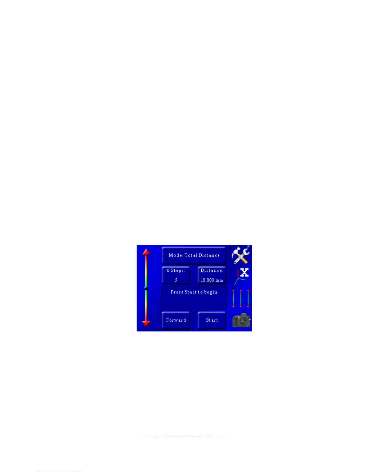
5.1.3 Mode: Total Travel Distance
In this operating mode (“Total Distance”) you can select the total distance the rail will travel
and the number of steps to use in that given distance.
5.1.3.1 Number of Steps
The “# Steps” option functions identically to the “Automatic Step” mode. It is the number of
steps (movements of the rail) by the specified distance below. To change the number of steps
press the “# Steps” button and enter the desired value.
5.1.3.2 Total Distance
Total distance (“Distance”) specifies the complete distance to move the rail. StackShot 3X will
automatically calculate the distance of each step required to result in the total distance desired.
5.1.3.3 Direction Desired
The direction defaults to “Forward”. To change the direction the rail will travel simply touch this
button to toggle between “Forward” and “Backward”.
5.1.3.4 Starting the Sequence
Exactly like “Auto-Step” mode, you press the “Start” button to begin the sequence.
When the stack completes you’ll be given the option to change the start and end positions or
run the stack again.
If you touch the screen any time during the stack it will stop the motor, abort the sequence, and
the display will show “Aborted” and give you the option to start the sequence again.
See Figure 5 below. The 2mm step size is determined by StackShot 3X. Just like “Automatic
Step” mode, the number of pictures taken is always “# Steps” + 1.
29
Page 30
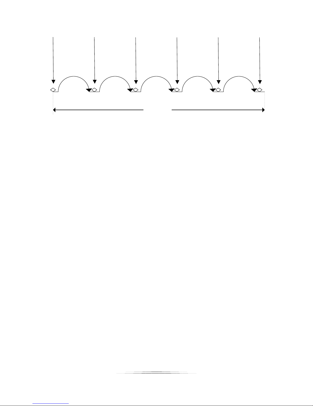
Step 1
(2mm)
Step
2
(2mm)
Step 3
(2mm)
Step 4
(2mm)
Step 5
(2mm)
Pic 1 Pic 2
Pic
3
Pic 4 Pic 5 Pic 6
10 mm
Figure 5 - Total Distance Mode
30
Page 31
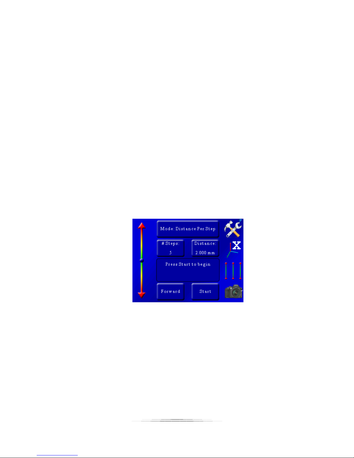
5.1.4 Mode: Distance per Step
The “Dist Per Step” operating mode lets you specify the distance to travel per step. It is similar
to “Total Distance” except here you explicitly specify the distance each step should be (rather
than the total distance).
5.1.4.1 Number of Steps
The “# Steps” option functions identically to the “Automatic Step” mode. It is the number of
steps (movements of the rail) by the specified distance below. To change the number of steps
press the “# Steps” button and enter the desired value.
5.1.4.2 Distance per Step
The distance the rail travels per step (“Distance”) is the amount traveled each time the rail is
automatically moved. To adjust this value press the “Distance” button and enter the desired
distance for each move of the motor.
5.1.4.3 Direction
The direction defaults to “Forward”. To change the direction the rail will travel simply press this
button to toggle between “Forward” and “Backward”.
5.1.4.4 Starting the Sequence
Exactly like “Auto-Step” mode, you press the “Start” button to begin the sequence.
This mode functions similarly to the “Total Distance” mode. The total distance traveled is the
number of steps multiplied by the distance per step. With the above configuration, StackShot
3X would perform identically as shown in Figure 5.
If you touch the screen any time during the stack it will stop the motor, abort the sequence, and
the display will show “Aborted” and give you the option to start the sequence again.
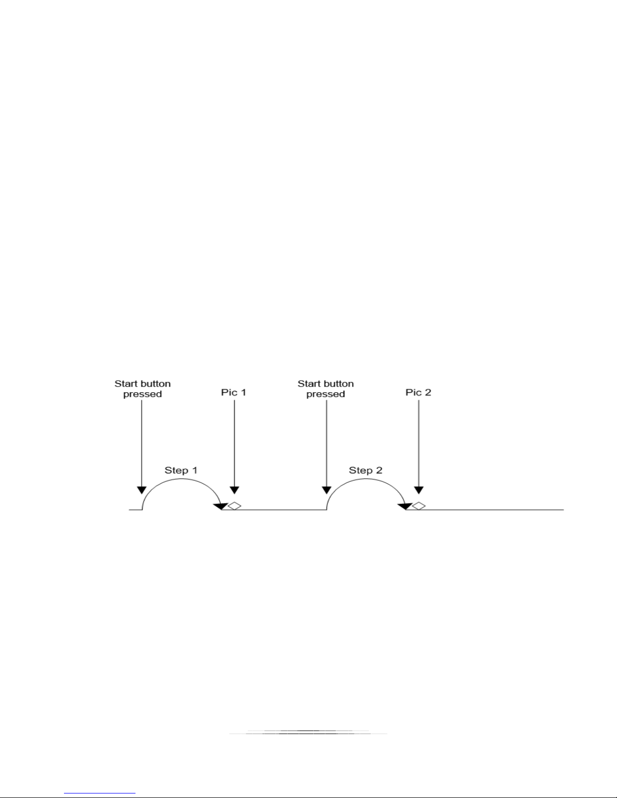
5.1.5 Mode: Manual
“Manual” mode is similar to “Distance Per Step” mode in that it lets you specify the distance to
travel per step, but it will only step the specified distance once after the “Start” button is
pressed. This gives the opportunity to make small adjustments to camera settings if necessary.
31
Page 32
5.1.5.1 Distance per Step
The distance the rail travels per step (“Distance”) is the amount traveled each time the rail is
automatically moved. To adjust this value press the “Distance” button and enter the desired
distance for each move of the motor.
5.1.5.2 Direction
The direction defaults to “Forward”. To change the direction the rail will travel simply press this
button to toggle between “Forward” and “Backward”.
5.1.5.3 Starting the Sequence
Press the “Start” button to move the rail one step.
If you touch the screen any time during the stack it will stop the motor, abort the sequence, and
the display will show “Aborted” and give you the option to start the sequence again.
See Figure 6 below to show how “Manual” mode functions.
Figure 6 - Manual Mode
32
Page 33
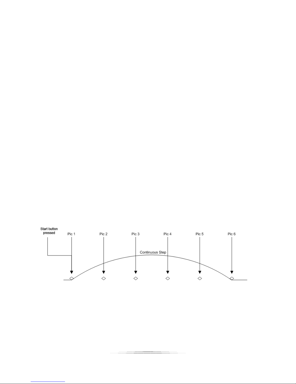
5.1.6 Mode: Continuous Movement
For Continuous mode (“Continuous”) you select the total distance the rail will travel. The rail
will not stop until it reaches its final position. During this time the shutter output(s) will fire
continuously. The shutter on and off time ultimately set the number of pictures that may be
taken during the rail move. Those parameters are available under the “Shutter Output
Settings”. See section “8.5 - Shutter Output Settings” for more details. Because the number of
pictures is dependent upon the time selected, a picture at the final position is not guaranteed.
Also keep in mind that the rail accelerates and de-accelerates. If the ramp time for this axis
(See section “8.2 – Axis settings“) is long it will affect the amount of distance traveled between
pictures (the time is fixed between pictures, not the distance).
5.1.6.1 Total Distance
Total distance (“Distance”) specifies the complete distance to move the rail.
5.1.6.2 Direction
The direction defaults to “Forward”. To change the direction the rail will travel simply press this
button to toggle between “Forward” and “Backward”.
5.1.6.3 Starting the Sequence
Press the “Start” button to begin the movement of the rail.
If you touch the screen any time during the stack it will stop the motor, abort the sequence, and
the display will show “Aborted” and give you the option to start the sequence again.
See Figure 7 below to show how “Continuous” mode operates.
5.1.7 Mode: Auto/Manual Advance
Auto/Manual Advance mode is identical to “Automatic Distance” mode (see section 5.1.2)
except that each step must be manually advanced. This is useful for applications where the
Figure 7 - Continuous Mode
33
Page 34
camera, subject, dye, or material may have a variable amount of time before the next picture is
desired. This mode is geared toward specialized applications and we would recommend the
use of “Automatic Distance” under most circumstances.
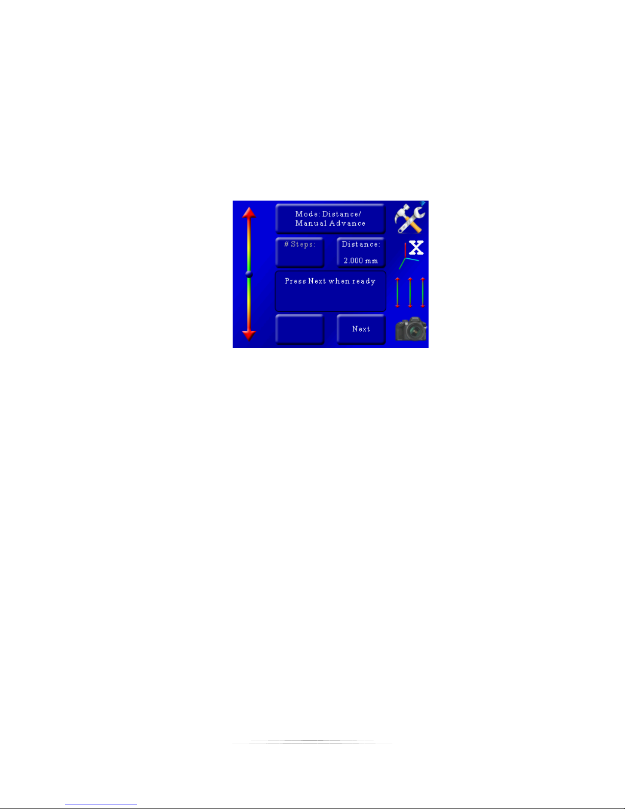
5.1.7.1 Advancing the rail
After the start and stop points have been selected like in the “Automatic Distance” mode, the
rail will automatically move to the start point and take the first picture (or pictures). Once the
shutter activates, the rail will move to the next position. You will then see the following:
At this point press the “Next” button to advance to the next step.
5.1.8 Mode: Auto-Rotary
“Auto-Rotary” is similar to the “Auto-Distance” mode except that it is designed for rotary tables.
This mode will use the rotary table parameters in the settings.
5.1.8.1 Degrees per Step
“Deg/Step” is the rotational distance the rotary table will move for every step. To adjust this
angle press the “Deg/Step” button and enter the desired angle you would like the rotary table to
move per step.
5.1.8.2 Selecting the Start/End Positions
Use the position slider on the left to find the appropriate beginning of the picture sequence.
Once happy with that position, press the “Set” button. The status window will change to “Select
the end position”. Again, use the position slider on the left to choose the final position of the
sequence. Press the “Set” button to confirm the end position.
34
Page 35
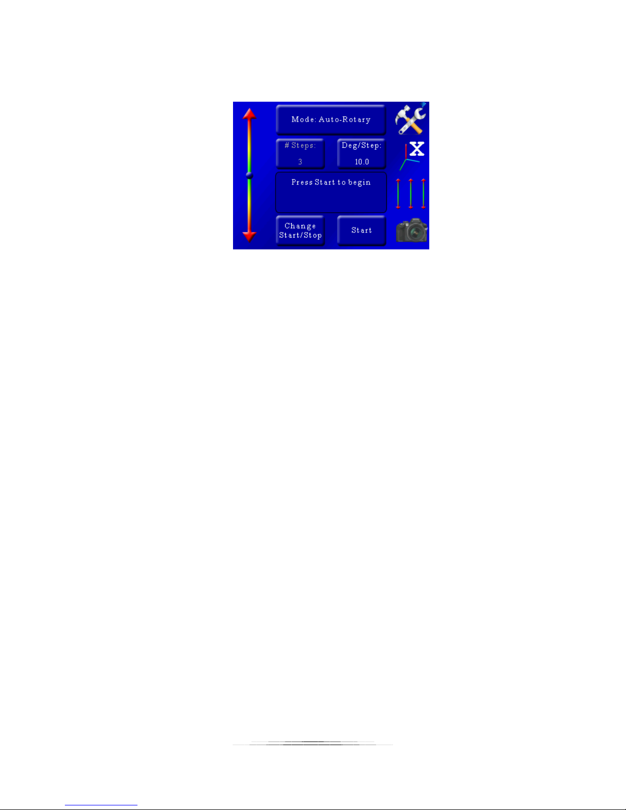
5.1.8.3 Starting the Sequence
Once the final position has been selected, the status will change to “Press Start to begin”:
Exactly like “Auto-Step” mode, you press the “Start” button to begin the sequence.
When the stack completes you’ll be given the option to change the start and end points or run
the stack again.
If you touch the screen any time during the stack it will stop the motor, abort the sequence, and
the display will show “Aborted” and give you the option to start the sequence again.
5.1.9 Mode: Rotary
“Rotary” mode is intended for use with rotary tables. In this mode you specify the number of
steps and the distance to move per step
5.1.9.1 Number of Steps
The “# Steps” option functions identically to the “Automatic Step” mode. It is the number of
steps (movements of the rotary table or motor) by the specified distance below. To change the
number of steps press the “# Steps” button and enter the desired value.
5.1.9.2 Degrees per Step
“Deg/Step” is the rotational distance the rotary table will move for every step. To adjust this
angle press the “Deg/Step” button and enter the desired angle you would like the rotary table to
move per step.
5.1.9.3 Direction
The direction defaults to “CCW” (Counter-clockwise). To change the direction the rotary table
will travel press this button to toggle between “CCW” and “CW”.
35
Page 36
5.1.9.4 Starting the Sequence
Exactly like “Auto-Step” mode, you press the “Start” button to begin the sequence.
If you touch the screen any time during the stack it will stop the motor, abort the sequence, and
the display will show “Aborted” and give you the option to start the sequence again.
5.2 Stacking: X-R – Stack/Rotate
This stacking mode combines a StackShot Macro Rail with a rotation stage to create high depth
of field images of an object taken at different angles. A rotary table is required for this mode.
Stacking takes place on the X-axis using the “Automatic Distance” method while the Y-axis is
used for controlling the rotary table. This mode is perfect for creating virtual objects or 3D
models of subjects.
5.2.1 Stack/Rotate Main Screen
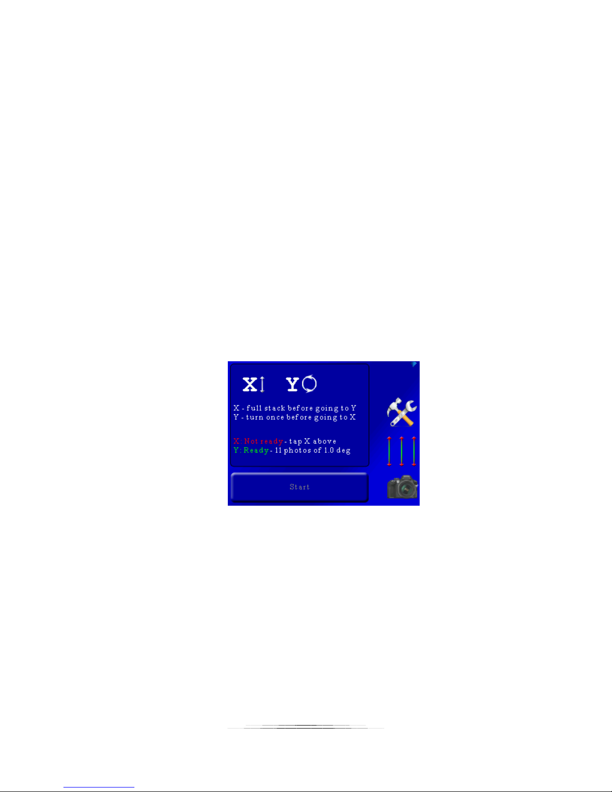
The main screen in this mode shows the number of pictures for each axis. Below is a screenshot:
Here the screen indicates that a full stack will be performed on the X-axis, then proceed to the
Y-axis for one move, and then return back to the X-axis for another full stack.
As you can see, the X-axis status is colored red saying that it is not ready. That is because a start
and end position have not been chosen. The Y-axis is ready to start since it has a default of 10
motor moves (11 photos) each of one degree. You’ll likely want to adjust that to your specific
requirements and is discussed below.
5.2.2 Adjusting/Setting the X-axis
To originally set the X-axis stacking position or to modify the current settings simply press the
“X” at the top of the main screen:
36
Page 37
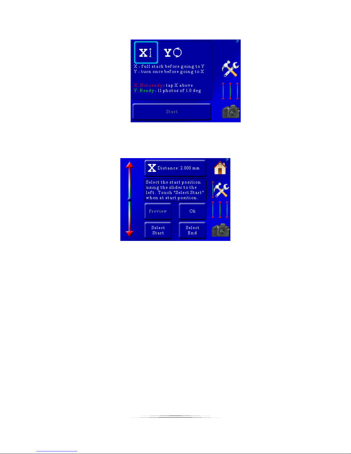
That will bring up the selection for the X-axis:
These settings are similar to the “Auto-Distance” mode in section 5.1.2. At the top of the screen
you will see “X Distance: 2.000mm”. This is distance the rail will move for your focusing steps.
To adjust this value simply press this button and enter the step size required.
You are also prompted to choose the start and stop position. First let’s choose the starting
position of this stack. Use the slider on the left side of the screen to position the rail at the
starting position of the stack and then press the “Select Start” button. The “Select Start” button
text will turn green.
Next use the slider on the left of the screen to move the rail to the end position of the stack.
Once at the required position press the “Select End” button. It will then turn green indicating
that it is confirmed.
37
Page 38
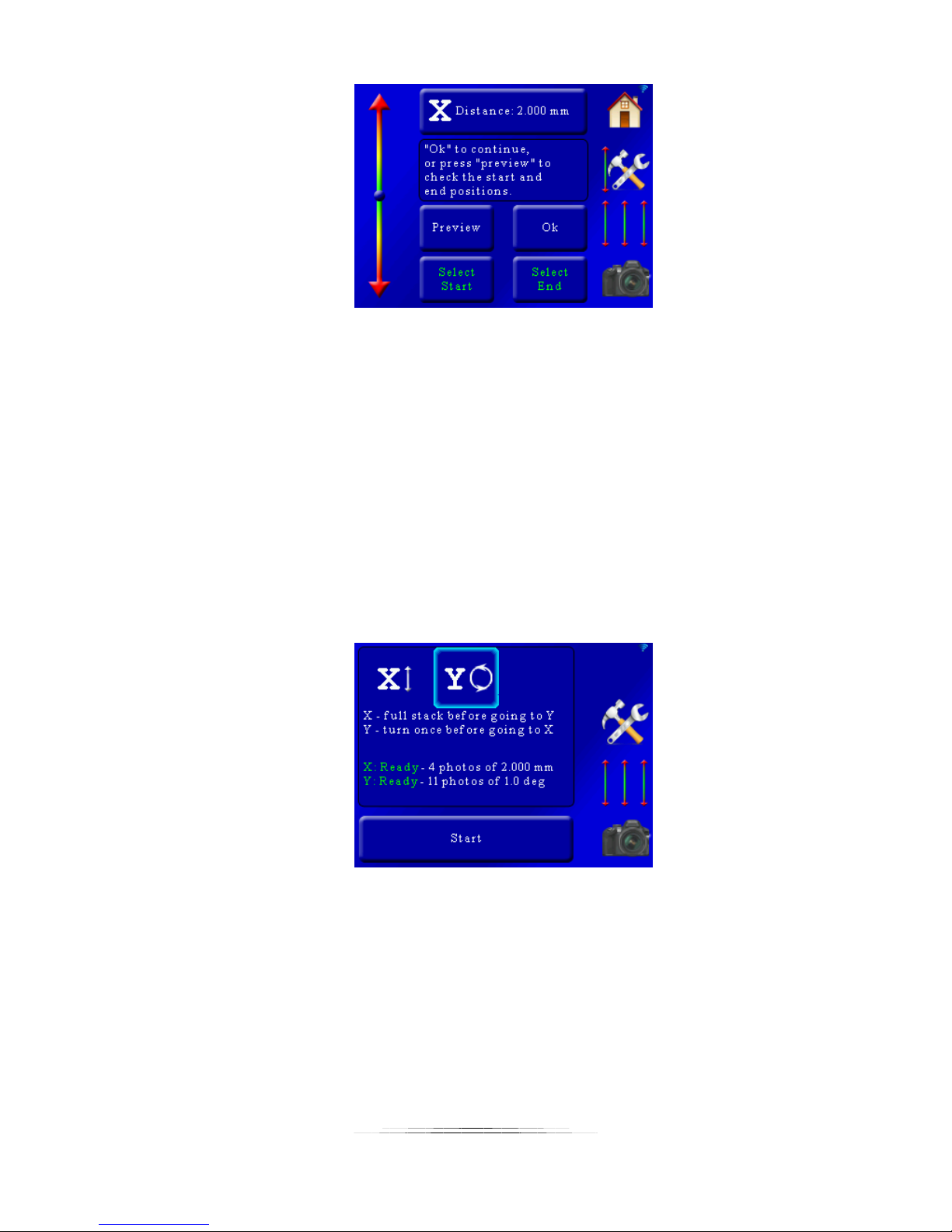
From here you can press “Ok” to return to the main screen. You can also optionally press the
“Preview” button. This will take a single picture at the beginning and the end of stack to verify
your composition. If everything looks good press the “Ok” button.
You can also return to this screen later if you ned to adjust the move distance or the the start
and end positions.
5.2.3 Adjusting/Setting the rotary position
Adjusting the rotary position and number of moves is similar to the linear rail. To make the
adjustment from the main screen press the “Y” at the top:
This will bring up the following screen:
38
Page 39
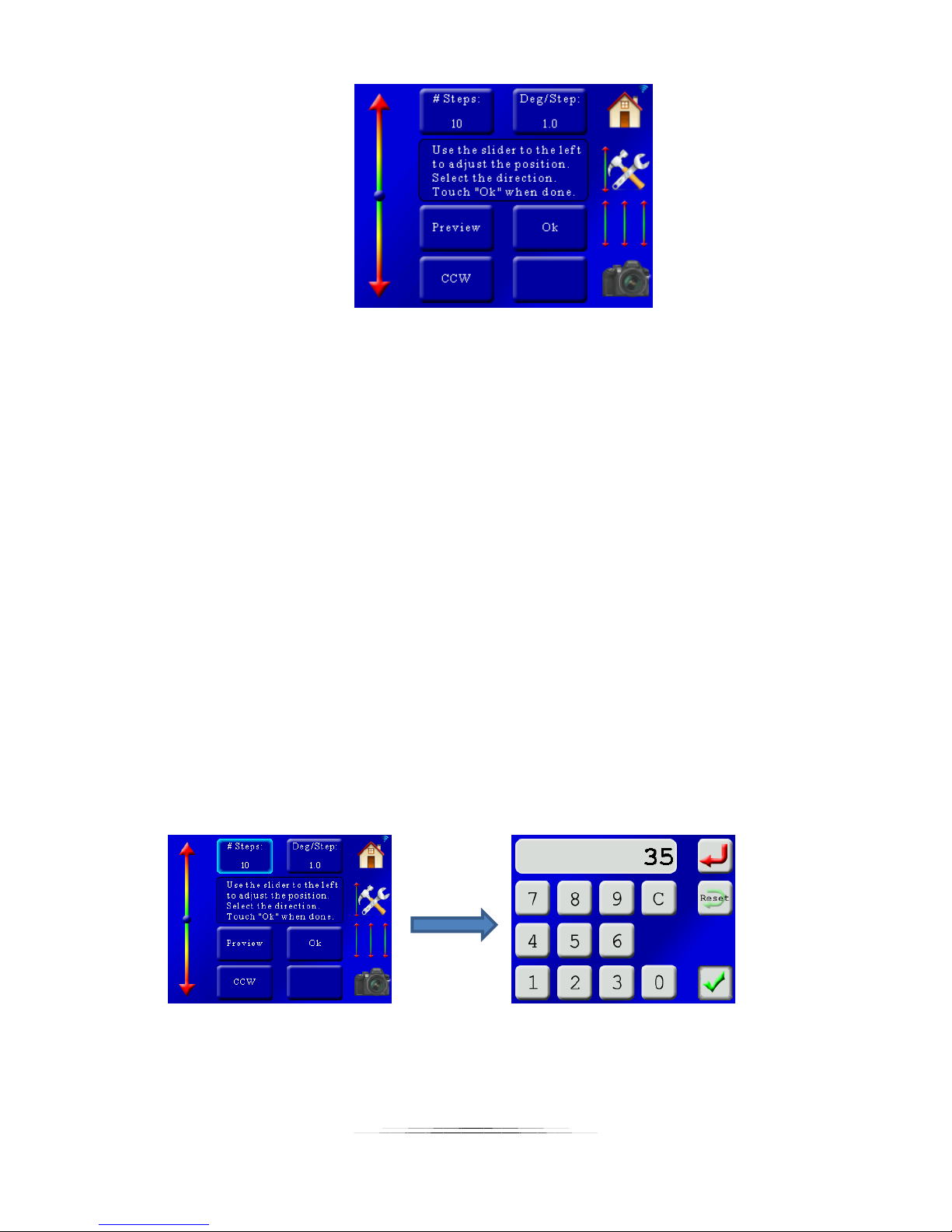
Using the slider on the left adjust the position of the rotary table to the starting point for the
stack.
You can adjust the number of steps (motor moves) by pressing the “# Steps” button and then
entering the number of steps. You can also adjust the number of degrees the rotary table
should rotate each step by pressing the “Deg/Step” button.
To adjust the direction of rotation press the “CCW” button. You can change back and forth from
“CCW” to “CW” (counter-clockwise or clockwise).
The “Preview” button will take a picture at the starting position and then at the final position to
verify your composition.
Example: Let’s say we want to take a 360 degree stacked image at 10 degree intervals. That
means the rotary table would have to move 35 steps of 10 degrees. Why 35 and not 36? The
stack starts at 0 degrees (which is the same as 360 degrees). If we set the rotation to rotate 360
degrees there would be duplicates at 0/360 degrees.
Here is the process:
Change the number of steps to 35:
Change the degrees per step to 10:
39
Page 40
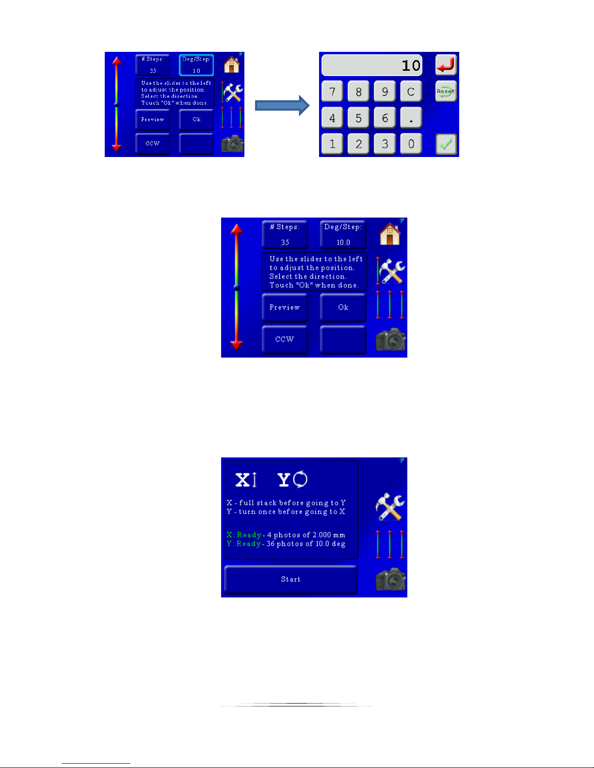
That results in the following screen:
Everything looks good! Press “Ok” to return to the main screen.
5.2.4 Starting the Stack/Rotate Stack
Continuing with our example our main screen now looks like the following:
There is green for both the X-axis and Y-axis. It also shows the number of photos. These
numbers will be important when adding them to your focus stacking software. It means that
each stack is four photos deep, and 36 across. There are file-sorting programs to move the files
into sub-directories to simplify the stacking process on your computer.
Press the “Start” button to start the stacking process. You will then see the following screen:
40
Page 41
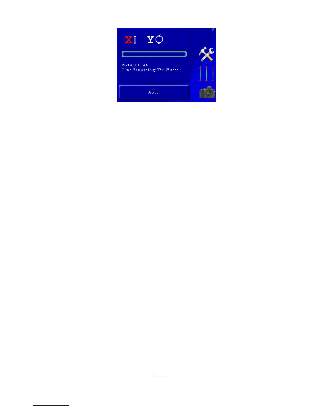
Here the current axis (“X” in this case) is in red indicating it active. The current and total number
of pictures is displayed along with the time remaining for the stack. The green bar-graph will
increase as the stack progresses. The time remaining for this stack is quite long due to a long
settle time for the X-axis.
5.3 Stacking: X-Y Scanning
X-Y scanning can be used in two different ways both using two macro rails.
1. Perform a stack on the X-axis. When this stack completes it moves the Y-axis the
specified amount and then returns back to the X-axis. This process continues until
the Y-axis reaches its final position. The Y-axis could be used to move the stacking
assembly left to right or up and down.
2. Perform a true X-Y scan. This is useful for giga-pixel scans of an object. An example
would be the X-axis moving left to right (handling rows) and the Y-axis moving top to
bottom (handling columns). These individual photos can then be stitched together.
The process for setting up the StackShot 3X is the same regardless of which final result you
desire.
5.3.1 Setting up the X or Y-axis
The process of setting up the axis is identical for each axis so only one will be shown. The main
screen of this mode shows both the X and Y-axis status:
41
Page 42
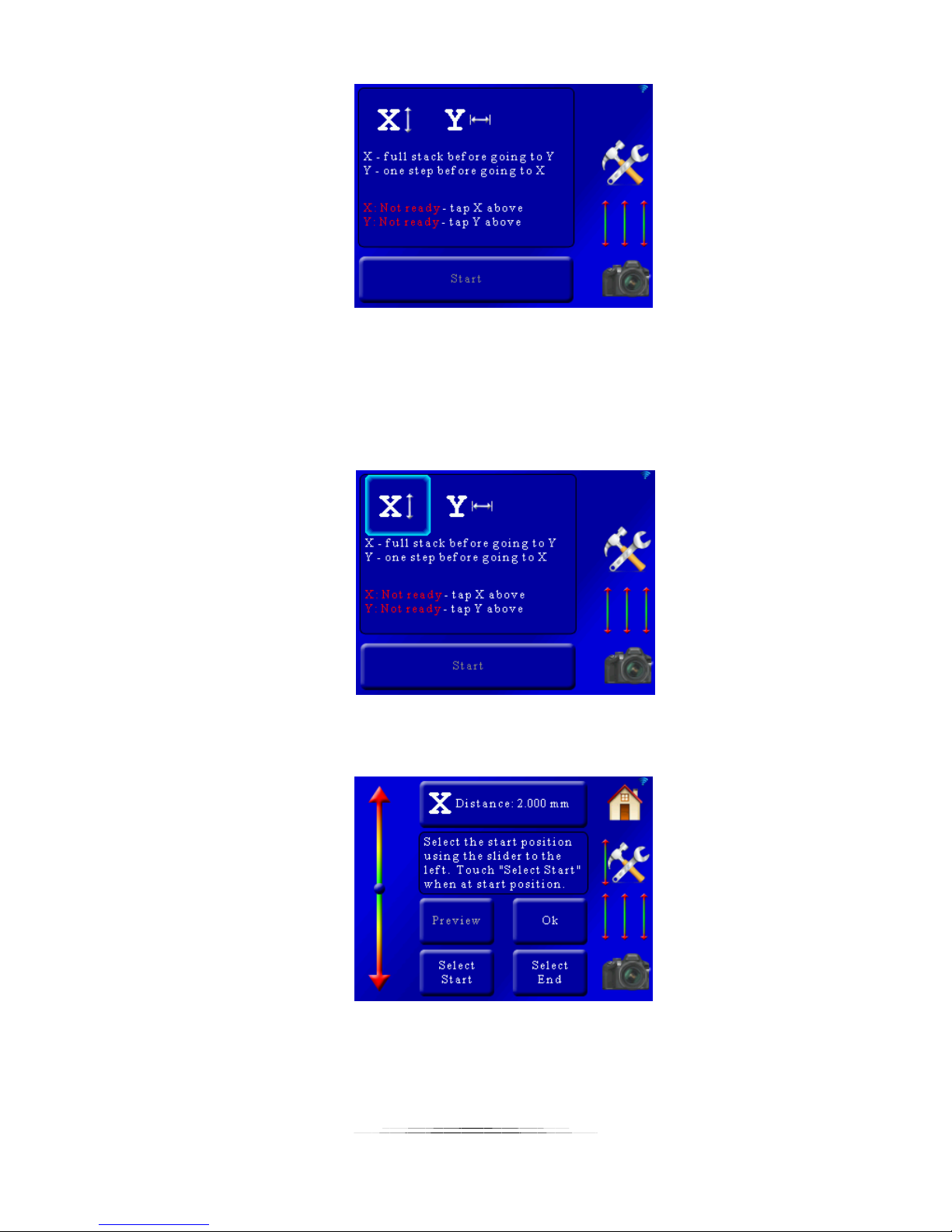
As you can see the X and Y-axis are not ready – the start and end positions need to be set. The
X-axis icon at top has a forward/back arrow next to it and the Y-axis has a left/right arrow.
These are completely arbitrary and are just shown to indicate a difference between the two. To
adjust the axis start and end positions press the “X” or “Y” at the top of the screen:
That will bring up the position settings for the X-axis:
These settings are similar to the “Auto-Distance” mode in section 5.1.2. At the top of the screen
you will see “X Distance: 2.000mm”. This is distance the rail will move for your focusing steps.
To adjust this value simply press this button and enter the step size required.
42
Page 43
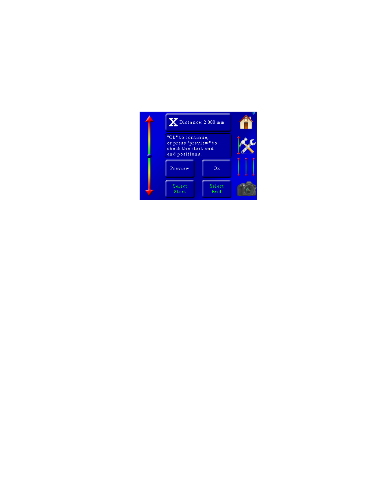
You are also prompted to choose the start and stop position. First let’s choose the starting
position of this stack. Use the slider on the left side of the screen to position the rail at the
starting position of the stack and then press the “Select Start” button. The “Select Start” button
text will turn green.
Next use the slider on the left of the screen to move the rail to the end position of the stack.
Once at the required position press the “Select End” button. It will then turn green indicating
that it is confirmed.
From here you can press “Ok” to return to the main screen. You can optionally press the
“Preview” button. This will take a single picture at the beginning and the end of the stack/scan
to verify your composition. If everything looks good press the “Ok” button.
You can also return to this screen later to adjust the move distance and start/end positions if
needed.
You will also need to set the Y-axis using this exact same process before you can start the
stack/scan.
5.3.2 Starting the X-Y Scan
Once you have selected the parameters for the X and Y-axis in the above section you will see a
screen similar to the following (depending on the distances and parameters you selected):
43
Page 44
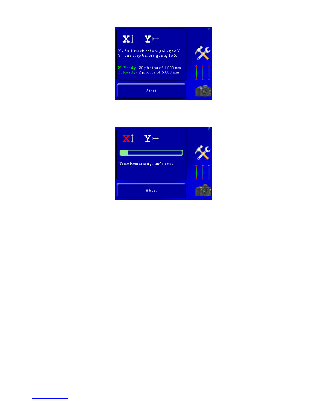
In this example the X-axis will take 20 photos deep, and the Y-axis will take 2 across. To start the
stacking process press the “Start” button. You will then see the following screen:
Here the current axis (“X” in this case) is in red indicating it active. The green bar-graph will
increase as the stack progresses.
44
Page 45

5.4 Stacking: X-Y-Z Scanning/Stacking
This mode is for focus-stacking large objects using three macro-rails. The X-axis is for focus
stacking, where the Y and Z-axis are intended for scanning across the surface being stacked.
This will allow you to stitch together focus-stacked images for a giga-pixel extended depth of
field image. The process is identical to X-Y scanning/stacking in the previous section 5.3 with
the addition of the Z-axis.
5.5 Stacking: X-R-Z Stack/Rotate/Move
This mode is a hybrid of X-Y scanning and X-stack / Y-rotate. It allows you to focus-stack and
rotate a large object using the Z-axis to move up and down creating slices of the object. The
process is as follows:
1. The X-axis completes a full stack.
2. The Y Axis rotates one step, and then returns to #1. If the Y-axis has completed its
full number of steps, then:
3. The Z-axis moves one step. It then returns to #1. If the Z-axis has completed its full
number of steps, the process is complete.
See section 5.2 and 5.3 for setting up the stack/rotate and scanning screens.
45
Page 46

6. Panoramic
A panorama is a sequence of images stitched together using photo stitching software.
StackShot 3X can automate panoramic image collection when coupled with the Cognisys rotary
table. There are three panoramic modes supported:
1. Single-Axis – Merge a single row of images using rotation.
2. Single-Axis 360 degree – merge a single row of images for a 360 degree rotation.
3. Multi-Row – Merge rows and columns of images using two rotary tables.
The process is similar between all three panoramic modes.
6.1 Panoramic: Initial Setup
6.1.1 Camera Settings
Before we get into how to use the controller let’s review some strategies for getting that perfect
panorama. Some of this may be obvious so apologies in advance! These are only guidelines and
certain shooting situations will require deviations from these suggestions.
6.1.1.1 Camera Mode
We recommend that your camera be in manual mode. You will want the exposure to be set
explicitly by adjusting the aperture, shutter speed, and ISO manually (NOT set to “Auto”) to
avoid/reduce exposure differences from frame to frame.
6.1.1.2 ISO
The ISO setting should not be set to “Auto” to avoid exposure differences. Typically a setting of
100 or 200 is reasonable.
6.1.1.3 Aperture
At least f/8, or even higher. The higher the f-stop the greater depth of field (DOF). So why not
just shoot at f/22 for maximum DOF? You will lose sharpness due to diffraction. The aperture
setting will be a balance of foreground and background DOF/focus and sharpness. Too low of an
f-stop and you could run into vignetting. If you see a darker exposure around the edges of each
frame then you should probably increase the f-stop.
Once the aperture is set adjust the shutter speed to set the proper exposure. It would be a
good idea to check the exposure at different points in the entire panorama so that no point is
over or under-exposed.
6.1.1.4 Auto-Focus
Typically you will want auto-focus off to prevent distortion in the final stitched image. The only
time you would want auto-focus on is when near-field objects would be out of focus at your
aperture setting. If you are going to use auto-focus be sure your focus point in your camera is
set to the proper location. Use auto-focus with caution since it could potentially ruin a beautiful
46
Page 47

panorama. If you decide to use auto-focus be sure to adjust the shutter duration settings in
StackShot 3X to account for any focus-hunting time (See section “8.5 – Shutter Output Settings“
for details on how to adjust this).
6.1.1.5 Lens
This is flexible depending on what you are shooting but there are a few restrictions. Avoid using
a lens at a very wide angle since the distortion will be visible from frame to frame.
Do not use a circular polarizer lens filter. The change in the angle of light reaching the lens can
cause unintended color gradients in large solid color areas (the sky is a perfect example).
If your lens has image stabilization be sure to turn it off.
6.1.1.6 Exposure bracketing (HDR) and mirror lock-up
You can easily take HDR panoramas using your StackShot 3X controller. First you would need to
enable exposure bracketing in your camera. Your camera then expects to see a fixed number of
shutter presses to cycle through all the exposures. If you set your camera for three brackets you
would need three activations of the shutter. This means that the controller would have to be
programmed to activate the shutter output that same exact number of times otherwise the
bracketing and the moving of the motor would become out of sync. This is easy to adjust. On
the controller go to Settings->Shutter Output Settings->Shutter 1 pics per move. More details
on the shutter output settings can be found in section “8.5 - Shutter Output Settings”.
The same holds true for mirror lock-up. If mirror lock-up is enabled in your camera you will
need to activate the camera twice for each picture. The first activation swings the mirror up and
the second fires the shutter. For mirror lock-up applications the “Pics per move” setting should
be set to two.
6.1.1.7 Test Pictures
Before you commit to a 100+ picture panorama be sure to take test shots at different locations.
The exposure can change significantly from one location to the other and it may be a fine
balance between over and under-exposure. Embrace your camera’s histogram if you haven’t
already.
6.1.2 Setting the aspect ratio
First you will want to set the aspect ratio for your camera. This is the ratio of width to height.
The default setting in StackShot 3X is 3:2 which covers most DSLR cameras in landscape
orientation. If your camera has a different ratio then you can adjust it by pressing the settings
button:
47
Page 48

and then scroll to “Aspect Ratio”. StackShot will remember this ratio – you don’t have to change
it unless you change to a camera with a different aspect ratio or change the camera orientation
from landscape to portrait. If you are currently in landscape mode (camera attached by its
bottom to the rotary table) with a 3:2 aspect ratio camera and then decide to rotate your
camera to be side-mounted, your aspect ratio would then be 2:3. Be sure to change it of
changing your camera mounting style.
6.1.3 Setting the overlap
Another important panoramic setting is the percent overlap. This is also under the settings
menu. The default overlap is 30%. This is the minimum overlap and there may be a higher
percentage depending on the beginning and end points. How much is required? That depends
on a couple of things. First is how much overlap your stitching software would like to see (which
likely isn’t published – enter the “trial and error” method). The other factor that drives the
amount of overlap is near-field/far-field content. The higher percent of overlap the safer you
will be but it will significantly increase the time it takes to finish the panorama. The more time it
takes – the greater the chance “that guy” will walk into the shoot.
6.1.4 Setting the field of view
The next part of the process is to determine your camera’s field of view (FOV). This will depend
on the lens, zoom, and sensor type of your camera. StackShot will save the previously used FOV
but if anything has changed in the camera setup you should set the new FOV. If you change to a
different lens or adjust the zoom be sure to set the new FOV.
How is the FOV determined? It’s quick and easy!
1. Looking through the viewfinder or the LCD display on your camera find an object.
2. You will be asked to move the rotary table using the position slider so that this
object is on the left side of the viewfinder/display.
3. Then you’ll be asked to move it so that it is on the right side of the
viewfinder/display.
4. Done!
Now StackShot 3X knows how much your camera can “see” per frame. You only have to set the
width because the aspect ratio you set previously lets the controller know the ratio of width to
height.
The screens on the controller walk you through this process too – who wants to read a manual?
48
Page 49
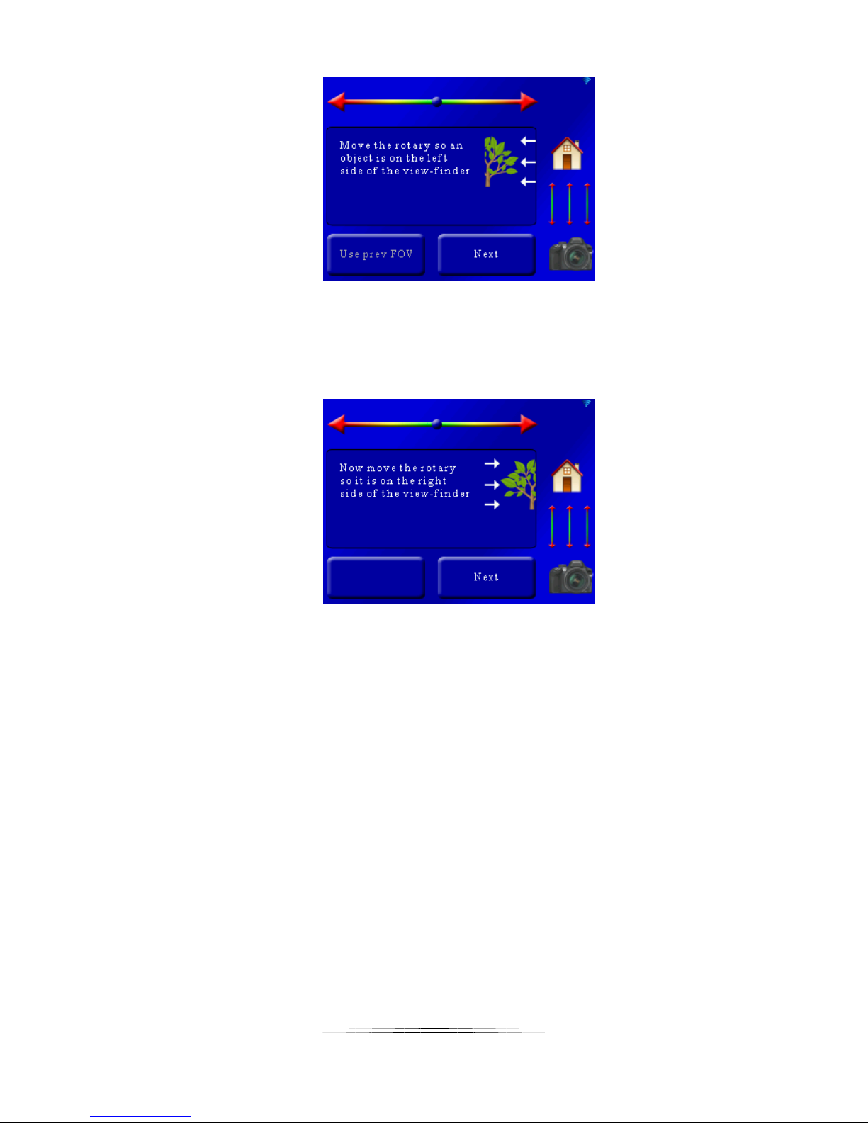
Here we can see the “Use prev FOV” is grayed out. You’ll see this if you haven’t set the field of
view yet (there is no previous!). To set the FOV use the position slider at the top and move the
camera so the object is on the left of the viewfinder. Once the position is correct press the
“Next” button. You’ll then see:
Now the controller is asking you to use the position slider so that the object is on the right side
of the viewfinder. Once there, press the “Next” button. Your FOV is now set!
Now for a little secret: It really doesn’t matter if you choose the left or right side first. It’s
arbitrary. So if for whatever reason you decide to start with the right instead of the left, that’s
okay too. The controller is forgiving if you’re one of those rule-breaker types.
49
Page 50
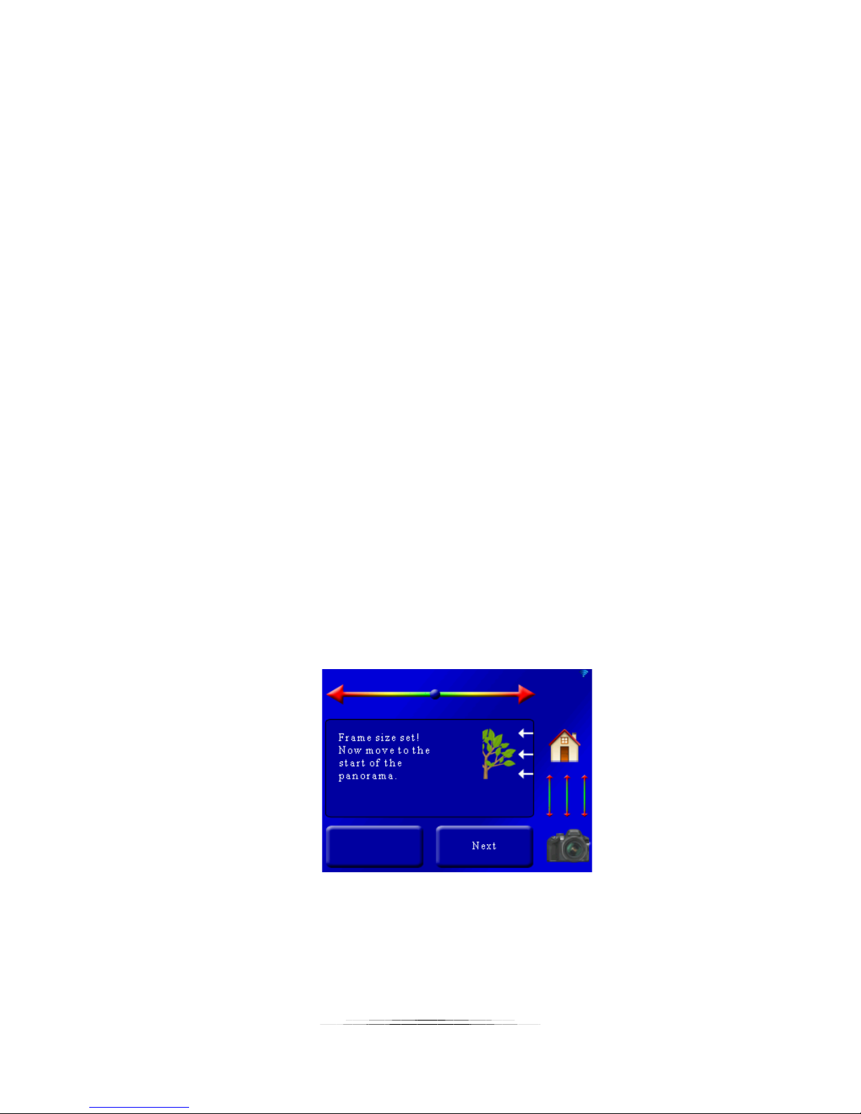
6.1.5 Checklist
Here are some is a list of gotchya’s to check before starting a panorama. These are all “obvious”
yet somehow we still skip one of the items on this list and have to reshoot a scene.
o Tripod stable for all camera positions
o Camera set to “Manual” mode
o Camera has enough storage for all the pictures
o Image stabilization off
o Auto-focus off – probably
o Auto-ISO turned off
o Exposure tested at different locations of the panorama
o Camera in single-shot only (continuous mode turned off)
o Level your camera – Tripod bubble or your camera’s digital level indicator
o Aspect ratio set properly
o Overlap set properly
6.2 Panoramic: Single Axis
This panoramic mode expects that the rotary table is attached to the X-axis. Before starting be
sure to have set your aspect ratio and percent overlap.
Once you have set your field of view (discussed in section 6.1.4) you are prompted to choose
the start of the panorama:
Use the slider at the top of the screen to adjust the rotary position to where you want the
panorama to start. Once the rotary table is at the start of the panorama press the “Next”
button.
Once you press “Next” you will be prompted to move to the end position:
50
Page 51
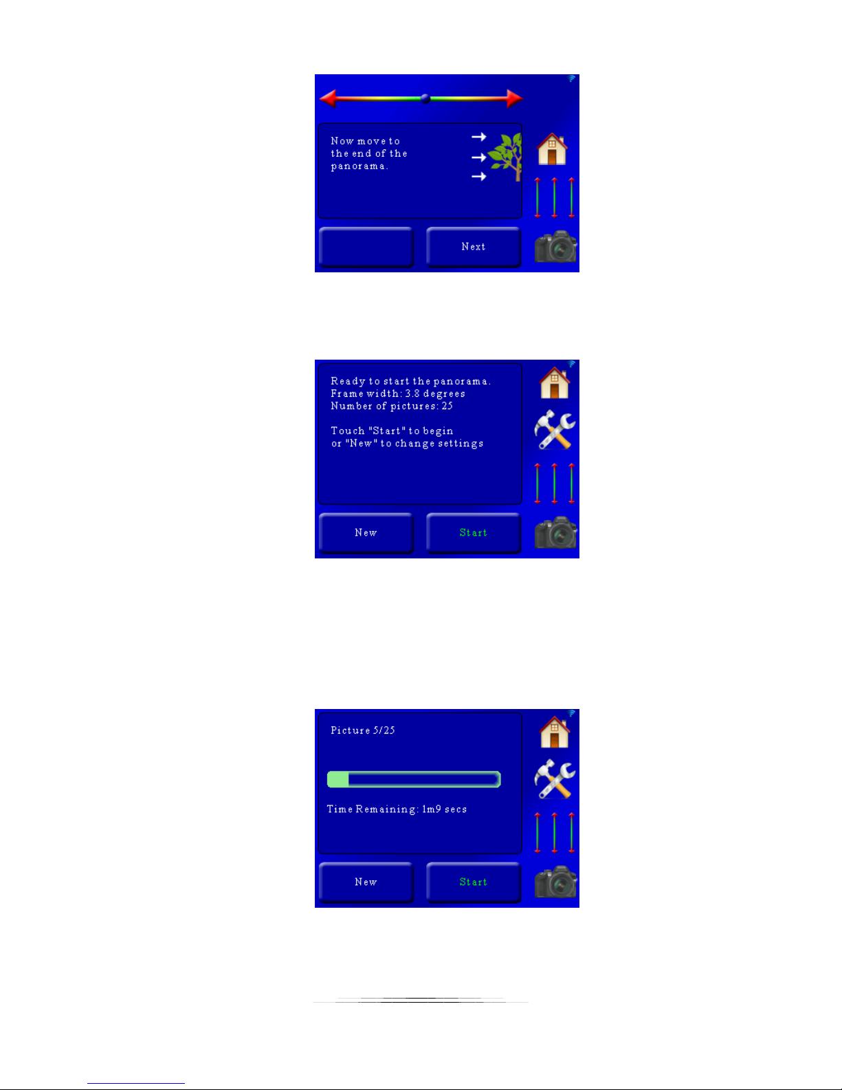
Use the slider at the top to adjust the rotary table to the end position of the panorama and then
press the “Next” button. You will then see a summary of the panorama before it begins:
For this example, during the FOV setup the rotary table was rotated about five degrees, and the
panorama was over roughly 90 degrees of rotation. So why does the frame width say “3.8
degrees”? That is because of the 30% overlap. The rotary table will move the 3.8 degrees every
time. You are prompted to either start over with a new panorama (which will take you back to
the beginning) or start the panorama. Once you press “Start” the panorama will begin and
show the current progress:
You can abort the panorama at any time by touching the screen.
51
Page 52
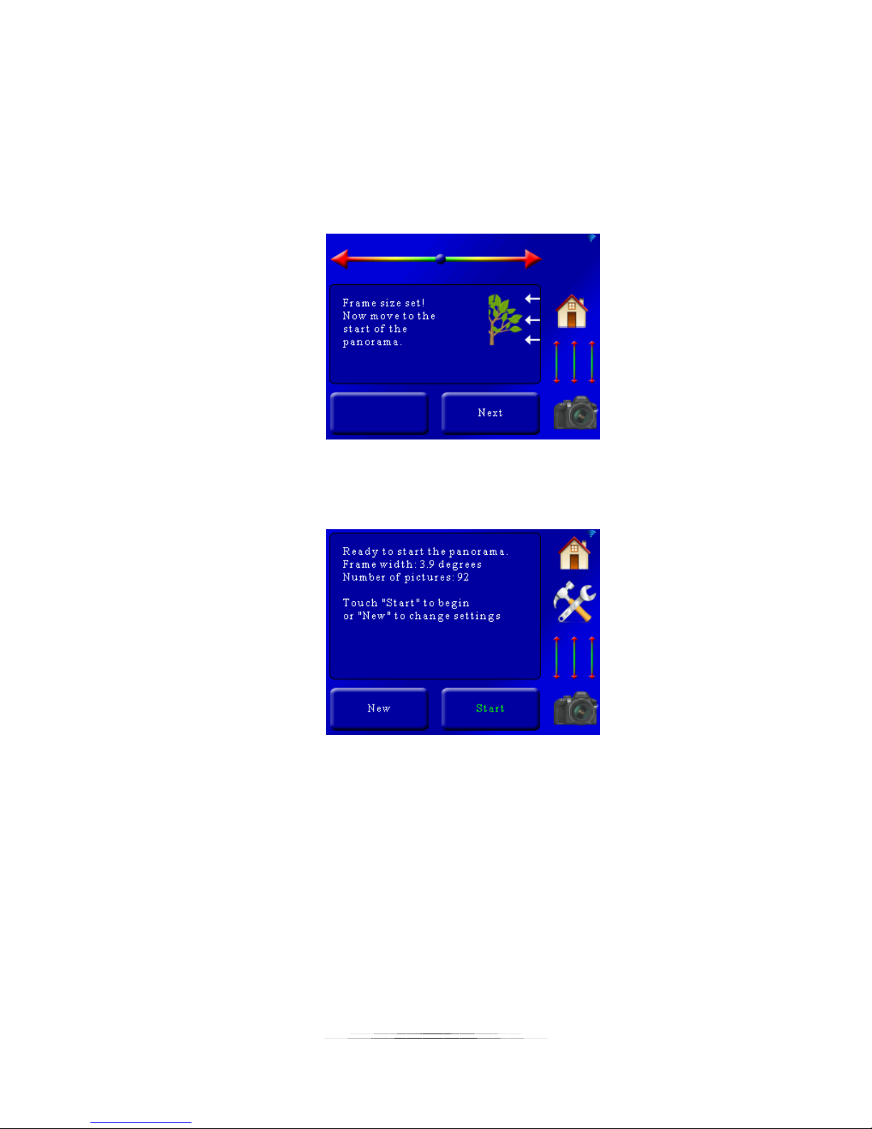
6.3 Panoramic: 360
This mode is similar to the single-axis with the exception that you do not have to choose both a
start and stop position. You only have to choose where the panorama will start. Just like the
single-axis mode, the rotary table must be attached to the X-axis.
Once the field of view is set you are prompted to move to the start of the panorama:
Use the slider at the top to adjust the rotary table to the beginning of the panorama. After that
press the “Next” button. You will then see a summary:
Here the frame-width is 3.9 degrees with a total of 92 pictures. To begin the panorama press
the “Start” button. Just like the single-axis mode, a status screen will keep you informed on the
progress of the panorama.
6.4 Panoramic: Multi-Row
Multi-Row panoramic requires the use of two rotary tables attached in their Pan/Tilt system
configuration. The X-axis is set up as pan, the Y-axis as tilt (X-axis is attached to a tripod, and
the Y-axis rotary is attached to the X-axis rotary table).
Multi-Row lets you pan and tilt your way through a scene to create a giga-pixel panorama. The
process is extremely simple:
52
Page 53
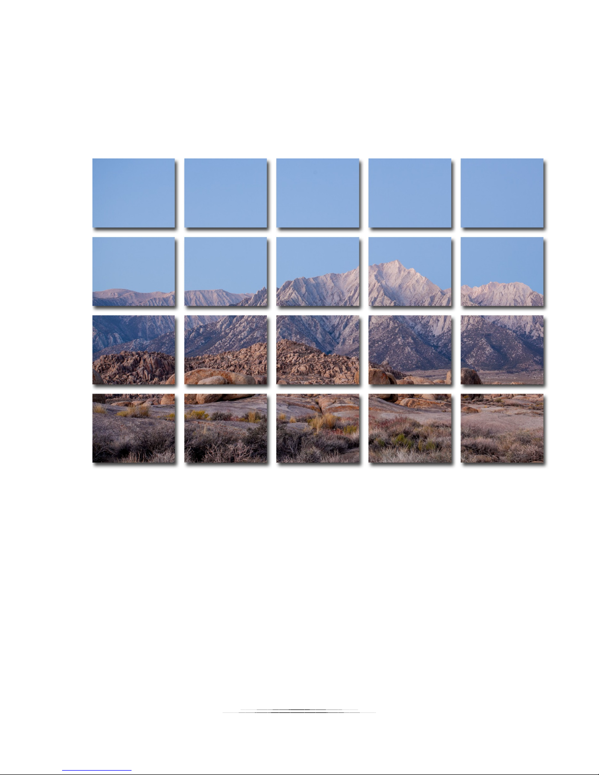
1. Set your field of view
2. Choose a start position
3. Choose an end position
4. Press start!
In this example we see a multi-row collection with four rows and five columns (20 total
pictures). It’s not quite a giga-pixel image – only 75 million pixels!
While collecting the images StackShot 3X will start at your initial selection and then zig-zag
toward the final location. This reduces the time spent moving the rotary system. In the above
example the starting position was in the upper-left and the end position was at the bottom
right:
53
Page 54
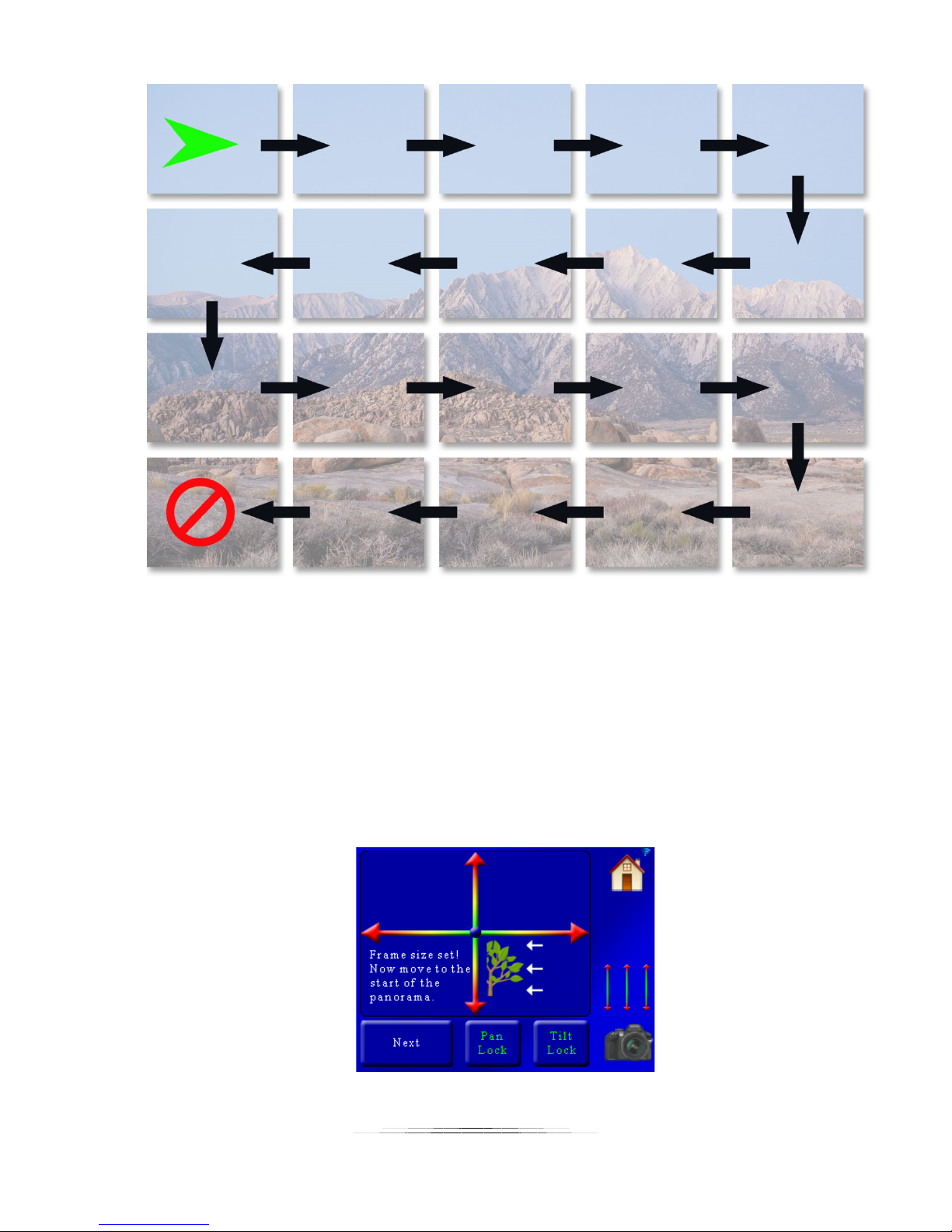
The series of photographs collected can then be stitched together using programs such as
Photoshop. The above order of the photographs may be required for the stitching program to
process the images correctly. As you can see, even though the starting point for the panorama
was in the upper-left and the end in the bottom-right, StackShot 3X ended in the bottom-left. It
still captured the bottom-right frame but the optimum motor path was to end in the bottomleft.
The field of view (FOV) setup is identical to the other panoramic modes and is discussed in
section 6.1.4. You can use a previously set up FOV or set a new one. Once your FOV is set you
will see the following screen:
54
Page 55
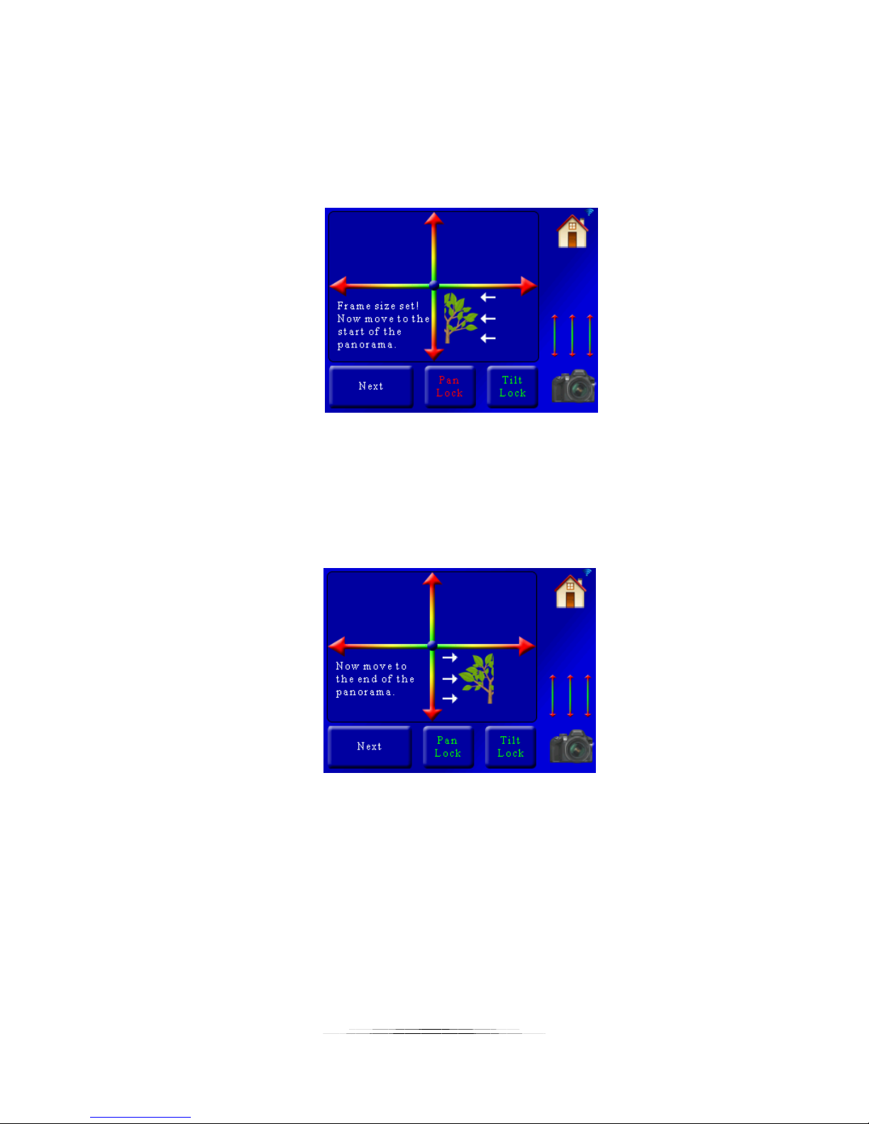
Here you can see you have two position sliders. The X-axis (left/right) allows you to pan and the
Y-axis (up/down) lets you tilt the position of your camera. You can adjust the position
simultaneously of both axes by touching a position between any point on the axes. You have
the option to lock the pan or tilt axis as well. If you touch the “Pan Lock” button you will see it
turn red:
When either the Pan or Tilt is locked it will not move that axis when using the position sliders.
This lets you fine-tune either axis as needed. If you want to unlock the axis simply press the
button again. Once it turns green the position sliders will let you move the axis freely again. In
this example we are selecting a position in the upper-left corner of the panorama. Once the
pan/tilt system is at the start position press the “Next” button. You will then see:
Once again use the position sliders to move the pan/tilt system to its final position. In this
example we will move it to the bottom right of the landscape. Once you are happy with the
final position press the “Next” button. You will then see the summary for the panorama:
55
Page 56
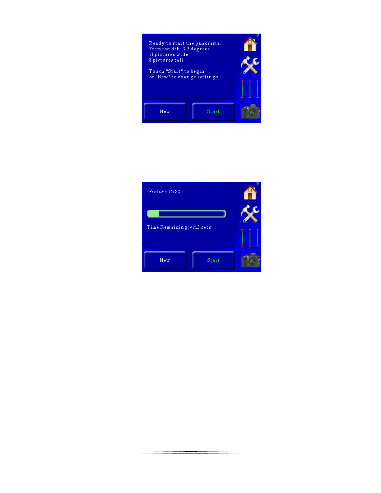
Here we can see the pan rotary table will move 3.9 degrees across for a total of 11 pictures, and
tilt for 8 pictures tall (88 total). If this setup looks acceptable press the “Start” button. The
system will return to the beginning position and begin the collection of photographs. While the
process is running you will see the current status:
When the panorama successfully completes it will return to the beginning position.
You can abort the process at any time by touching the screen.
56
Page 57

7. Motion Control
StackShot 3X is capable of several different motion control methods. They provide completely
fluid motion on all three axes in either real-time or time lapse operation. There are four motion
control modes that will be discussed in this section:
1. Video: Continuous. The motors are continually in motion. Ideal for video
applications. The shutter output is activated at the beginning of the move and at
the end. Because the motors are continuously consuming current this mode is not
recommended for long durations.
2. Timelapse: Continuous. The motors are continually in motion. Ideal for short or
fast time lapse movies. The shutter is activated at a fixed interval while the motors
are in motion. Not for use with long exposures unless you want motion blur.
Because the motors are continuously consuming current this mode is not
recommended for long durations.
3. Timelapse: Shoot-Move-Shoot. The motors are moved in discrete steps
periodically. This mode is geared toward long duration time lapse (hours and days).
4. DragonFrame DfMoco. StackShot 3X is tethered to a computer using DZED Systems
“Dragon Frame” software. This provides maximum flexibility and control of all three
axes. Extremely complex motion profiles can be programmed for shoot-move-shoot
time lapse.
All of these modes define the motion profile by using Bézier curves. Using these curves allows
for fluid motion, easy adjustments of parameters, and a visual representation of the path the
motion will follow. If you’re not familiar with Bézier curves, that’s okay! There is a “Helper”
button that will ask you a few questions and generate them for you. This “Helper”
accommodates most shooting requirements. If the helper can’t do exactly what you need there
is also advanced editing of key frames.
We go through a real-world example in section “10.3 – Motion – Shoot-Move-Shoot“.
CAUTION: Motion control can be dangerous to all of your camera equipment. Care should be
taken to prevent damage to your gear. 360 degrees of rotation might sound like a great idea
until you pick the wrong axis and grind your $3,000 lens right into the tripod. The torque
provided by the rotary tables is sufficient to cause significant camera equipment damage.
Additionally, using a slider can cause a large shift in weight. Motion control can yield incredible
results but it always has to be approached with a healthy dose of paranoia. You can stop the
axes from moving by pressing the display or removing power. Here comes the legal disclaimer:
Cognisys, Inc. is not responsible for damage to your equipment.
57
Page 58

7.1 Motion Control: Initial Setup
7.1.1 Camera Settings
Before we get into how to use the controller let’s review some strategies for getting that perfect
video. Some of this may be obvious so apologies in advance! These are only guidelines and
certain shooting situations will require deviations from these suggestions.
7.1.1.1 Camera Mode
We recommend that your camera be in manual mode. You will want the exposure to be set
explicitly by adjusting the aperture, shutter speed, and ISO manually (NOT set to “Auto”) to
avoid/reduce exposure differences (flicker) from frame to frame. Make sure the shutter speed
isn’t longer than your interval time – otherwise the gear will be moving while you’re still
exposing.
7.1.1.2 ISO
The ISO setting should not be set to “Auto” to avoid exposure differences between frames.
7.1.1.3 Aperture
This depends on the content that you are shooting. To avoid flicker in time lapse applications
you may want to consider a fully manual lens. What does that mean? It is a lens that you can
adjust the aperture on the lens itself (not through the camera).
7.1.1.4 Auto-Focus
Typically you will want auto-focus off to prevent distortion in the final video.
7.1.1.5 Lens
Do not use a circular polarizer lens filter. The change in the angle of light reaching the sensor
can cause unintended color gradients in large solid color areas (the sky is a perfect example).
If your lens has image stabilization be sure to turn it off.
7.1.1.6 Test Pictures
Before you commit to a 1000+ picture time lapse be sure to take test shots at different positions
along your motion profile. The exposure can change significantly from one location to the other
and it may be a fine balance between over and under-exposure. Embrace your camera’s
histogram if you haven’t already.
58
Page 59
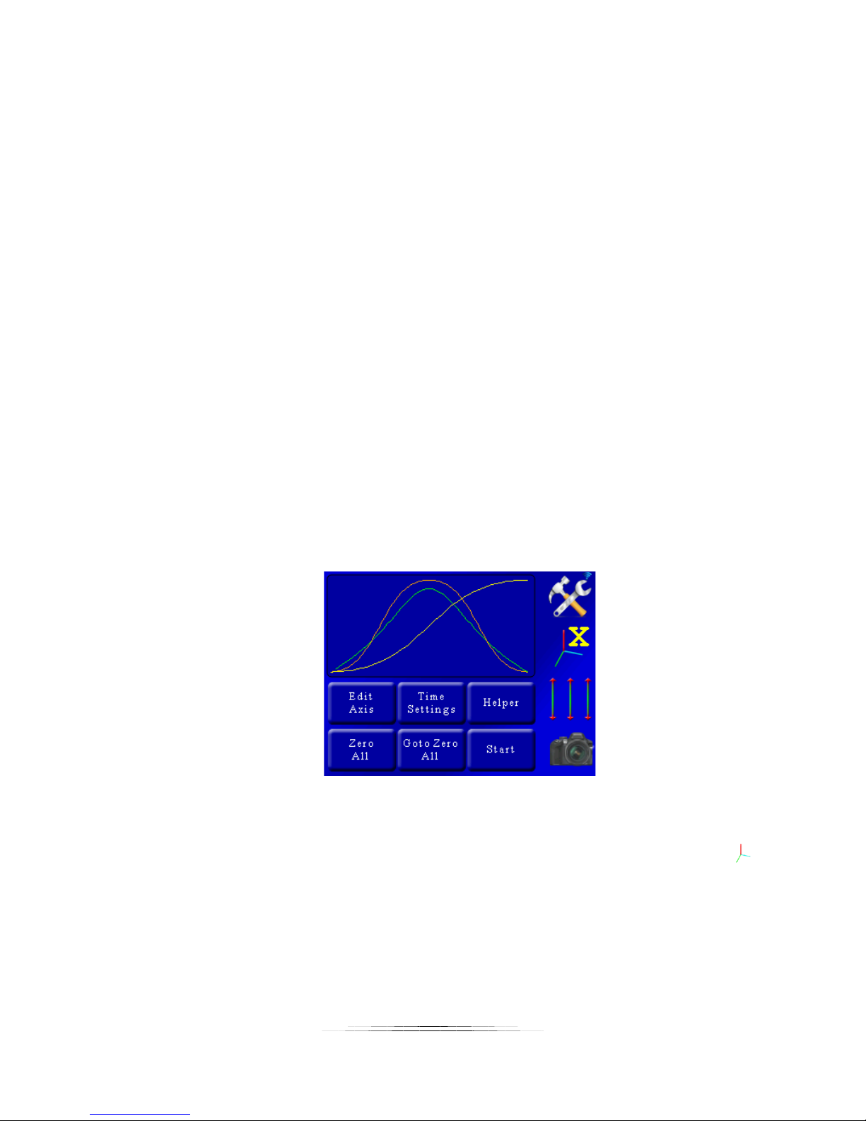
7.1.2 Checklist
Here are some is a list of gotchya’s to check before starting a motion profile. These are all
“obvious” yet somehow we still skip one of the items on this list and have to reshoot a scene.
o Slider/Tripod/Gear stable for all camera positions
o Camera set to “Manual” mode
o Camera has enough storage for all the pictures / video
o Fresh batteries all around!
o Image stabilization off
o Auto-focus off
o Auto-ISO turned off
o Exposure tested at different locations of the panorama
o Camera in single-shot only (continuous mode turned off)
o Camera shutter cable firmly attached to camera and StackShot 3X (do a test-shot!)
7.2 Motion Home Screen
The “Home” screen for the motion modes is identical (except for Dragon Frame control). From
here you can see all three axes and the path they will follow:
Here you are presented with the standard controls along the right-hand side. There are six
buttons available:
1. Edit Axis: Edit the motion profile of the currently selected axis (indicated by the )
2. Time Settings: Change shutter, video, lead-in, lead-out settings
3. Helper: This is your friend. The “Helper” button will ask a few questions and
generate the motion profile for you.
4. Zero All: All motion starts from position zero. This button will set the current
motor positions as zero.
59
Page 60
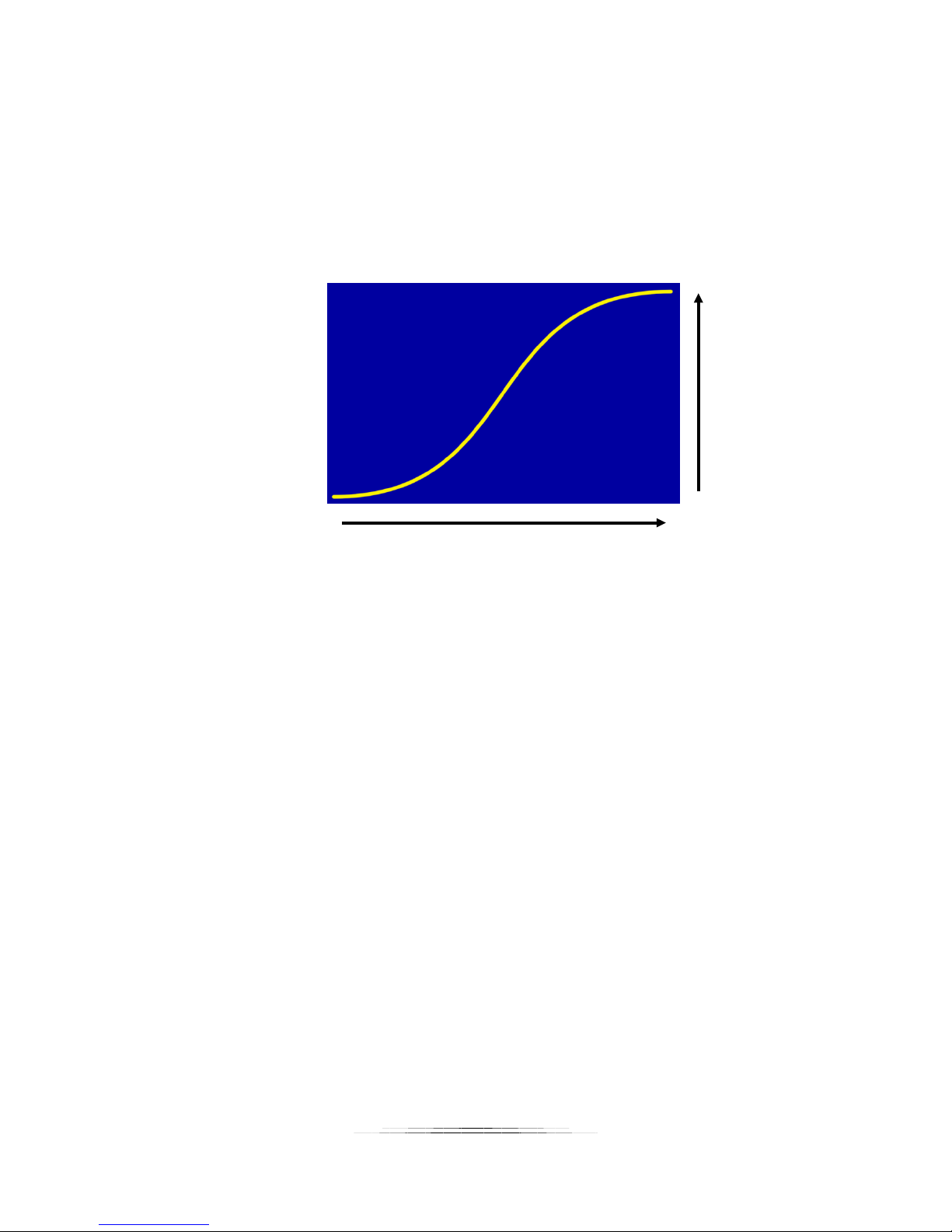
5. Goto Zero All: This will send all axes to their zero position. It will not follow the
motion profile to do this and will get to the zero location in a hurry.
6. Start: Begins the motion profile.
Now let’s discuss the curves and what they mean. Time is going left to right. The motors start
at time zero and run for the duration you specify (we’ll get to that in a bit). Position on the
other hand is bottom to top. Let’s take a closer look at the position curve (the one that isn’t
green):
Position
Time
As your motion profile runs time will move from left to right. The position moves up and down.
The starting position is on the left (time = 0), and the end position is on the right (at a duration
you specify). The curve above shows the position increasing as time goes on – the end position
on the right side is above the start position. Still not clear? Not a problem. Once you use the
helper in section “7.3 - Motion Helper” and run your first move it will clear things right up for
you.
You will also see a green curve. This is the velocity (speed) that this axis will move. If you see
red in this curve then you’re in trouble! Again, we’ll talk more about that below in section “7.5 Velocity Curve”.
7.3 Motion Helper
The Motion Helper is an easy way to set up a motion profile without the burden of using key
frames. Here are examples of using the motion helper.
7.3.1 Video: Continuous
From the main screen press the “Helper” button:
60
Page 61
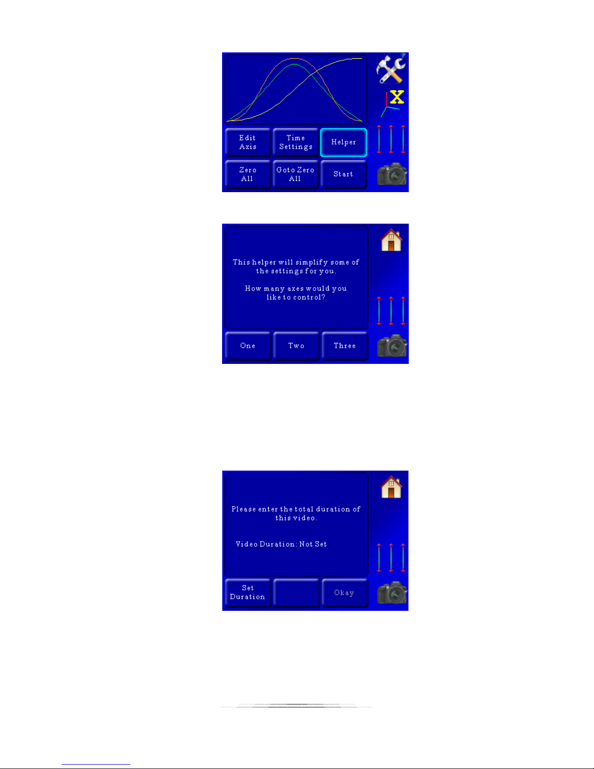
You’ll then be prompted for how many axes you plan to control:
We’re going to use all three for this example so we’ll press the “Three” button. If at any time
you want to abort the helper press the “Home” button.
Once we’ve pressed the “Three” button we’re asked another question. It depends on which
mode you’re in. For “Video: Continuous” mode you be asked to enter the total duration of the
video:
Since this is real-time video, the “Duration” is how long you would like the motors to move.
Press the “Set Duration” button and enter how long you would like this video to last. In this
example we’ll enter 30 seconds:
61
Page 62
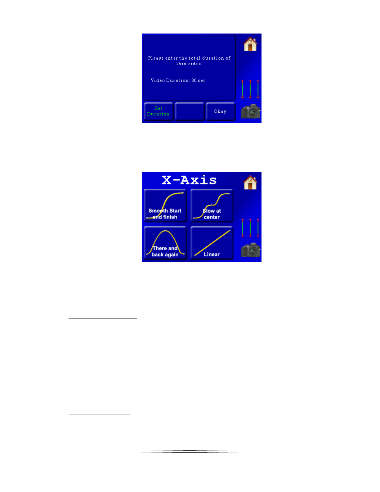
If you’re happy with the duration press the “Okay” button to continue to the next screen.
Now that the timing is set you’ll be asked about the specific axes:
At the top of this screen you can see that this question is about the “X-Axis” (can’t miss that!).
The helper is asking you which type of motion profile you would like to follow. There are four
available:
Smooth Start and finish:
This motion profile starts off slow and ends slow, while speeding up in the middle. The motion
is fluid throughout the move. Imagine using this on a pan. It would slowly start, increase speed
in the middle, and then slow down at the final destination.
Slow at center:
This is similar to “Smooth start and finish”, except that the motion slows down to a crawl at the
center of the motion profile. It’s a good way to draw attention to something going on at the
center of the scene.
There and back again:
This profile has the axis end up right back where it started. When would you use this? Let’s say
you used this on an axis set up to control tilt – While panning left to right the “there and back
again” on the tilt axis could walk up a rock peak or follow the contour of a road. Like the
62
Page 63
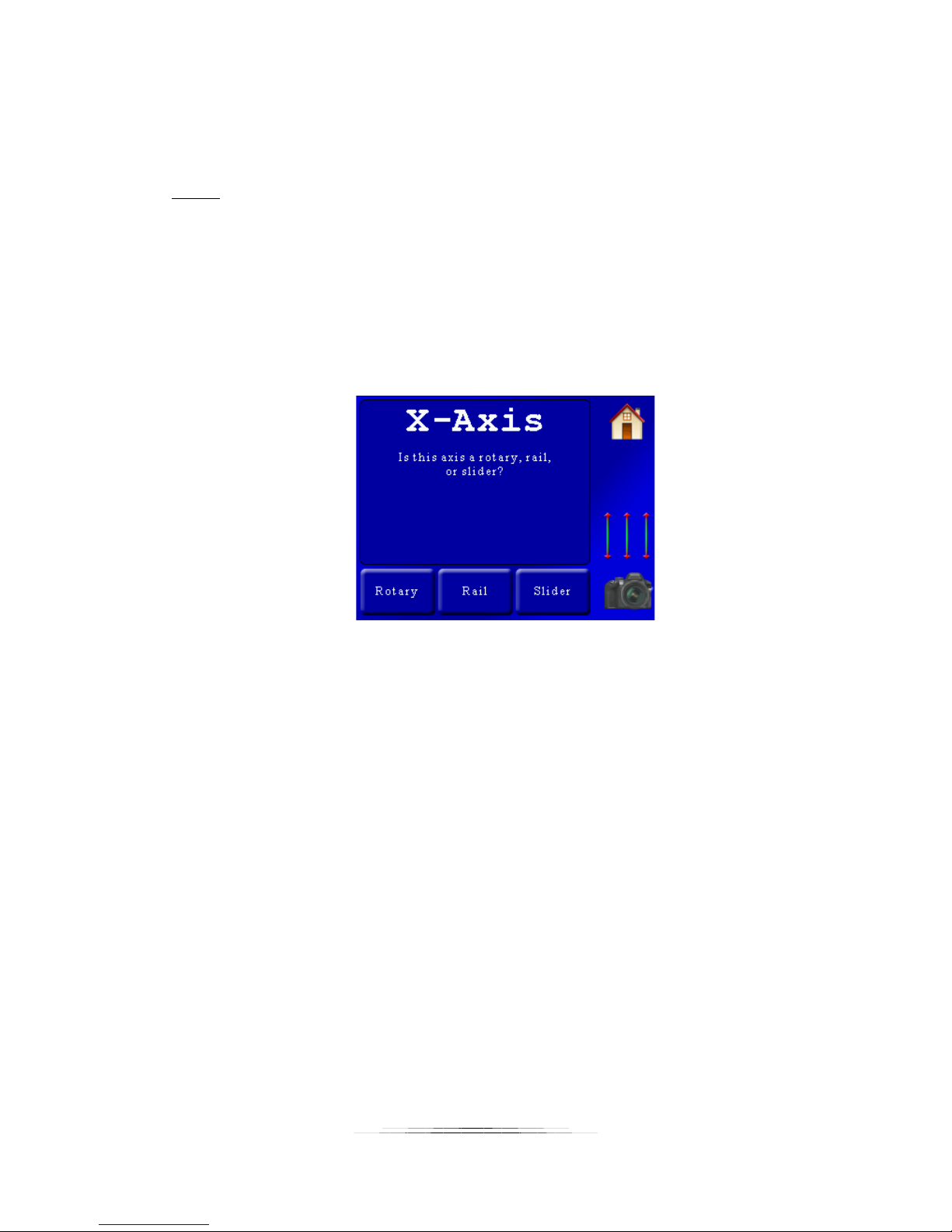
“smooth start and finish” it will ease in slowly and ease out slowly. The helper will later ask you
for the maximum travel (which is at the peak of this curve). That is how far it will travel before
returning back to the starting position.
Linear:
The speed for this axis is completely constant (no ramping at all). If you don’t want to easein/ease-out of the scene you are shooting you can use this profile to keep the pan/tilt/slide
constant. If using this in the “Video: Continuous” mode there will be jerk when you start
because the velocity is constant for the move.
Once you decide which motion profile you would like to use simply press it’s corresponding
button. In this example we’ll choose the “Smooth start and finish”. We’ll then be asked the
following:
StackShot 3X needs to know what type of gear you have connected to each axis. Double-check
your cables since it is easy to swap the pan/tilt. In this example, we have the X-Axis attached to
a rotary table so we’ll press the “Rotary” button.
We’re then immediately asked for the same questions for the Y-axis and Z-axis (because we told
the helper we planned on using three axes):
Y-axis motion profile (Smooth start/finish, linear, etc)
Y-axis attached gear (Rotary, rail, slider)
Z-axis motion profile
Z-axis attached gear
If at the beginning you selected only one axis then the prompts for the Y-axis and Z-axis
wouldn’t appear.
In this example we’re selecting the following options:
X-axis: Smooth start and finish
X-axis: Rotary
Y-axis: Smooth start and finish
Y-axis: Rotary
63
Page 64
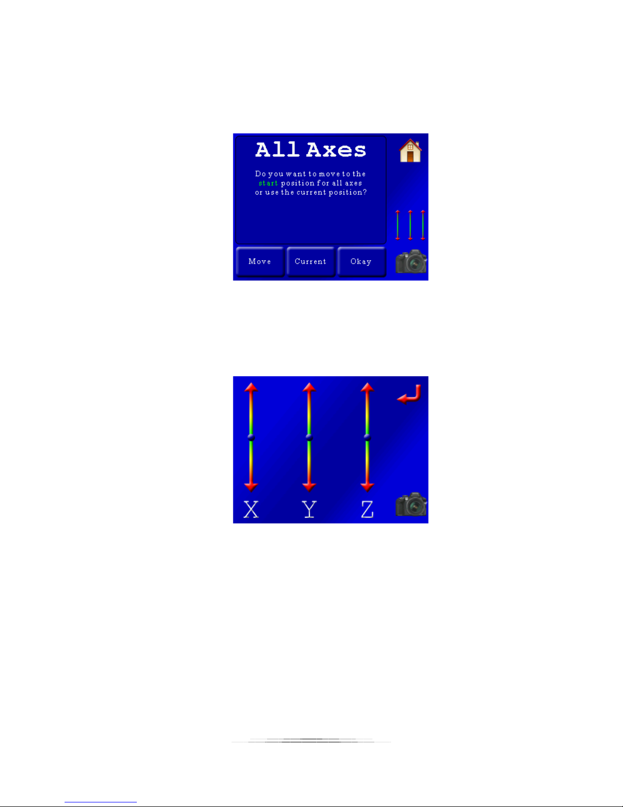
Z-axis: Smooth start and finish
Z-axis: Slider
Once we’ve selected the motion profile and the attached gear for each axis we’re prompted
with the following:
Here we are asked to choose the start position for all axes. You have to adjust the start position
for all three (or as many as you selected) axes. You have two options to choose from: Use the
“current” position (you’re already at the start) or “move” to the start position. If you press
“current” you’ll be taken to the next screen. If you press “move”, you will see the three-axis
slider to adjust the position:
Using the sliders above adjust the position for each axis to the starting point. When complete,
press the red “return” arrow.
If the starting position is good press the “Okay” button and then we will see:
64
Page 65
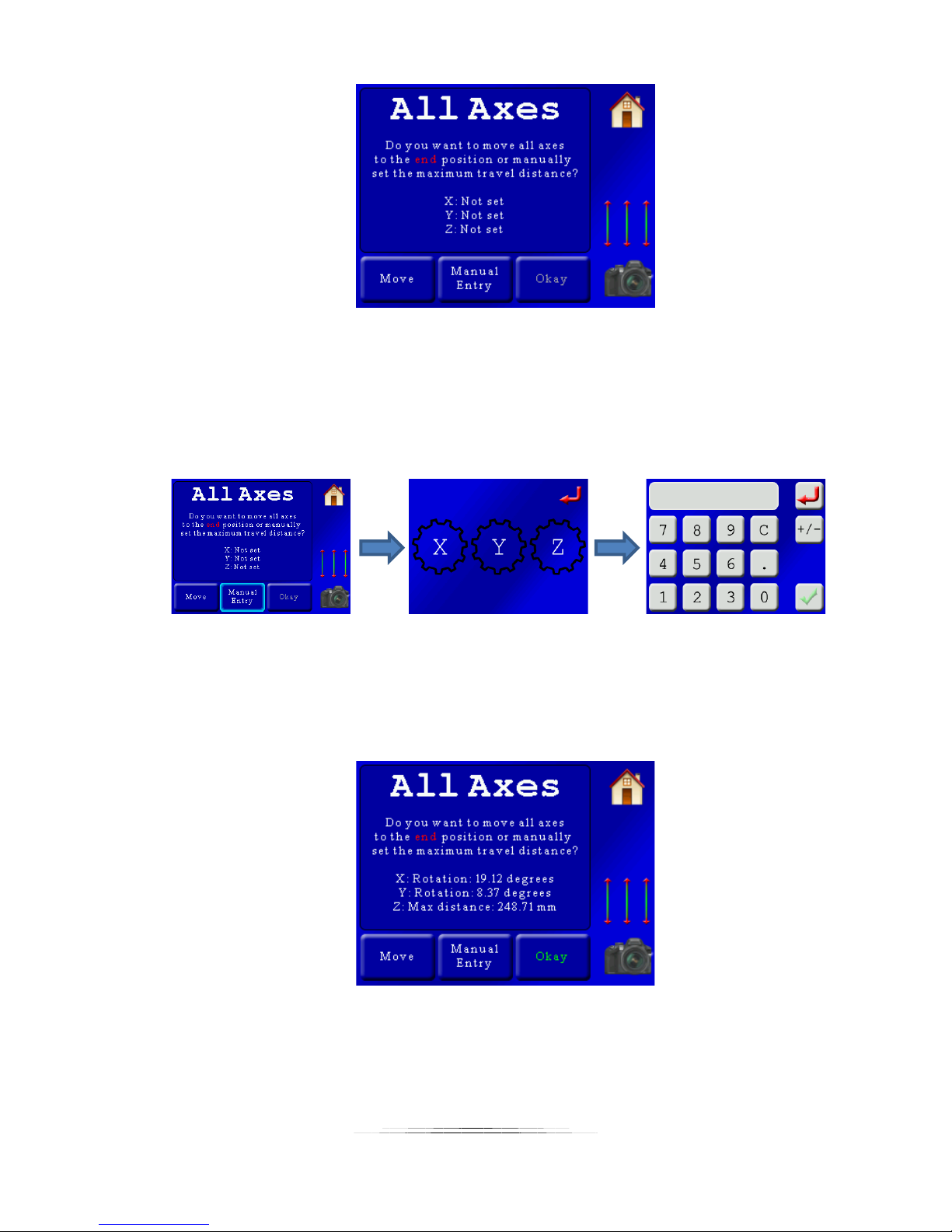
Now we need to set the end position for all axes. There are two options for choosing the end
position for all three axes (or as many as you have selected). If you press the “Move” button,
the three-axis slider will appear and you can adjust the position visually. If, however, you know
how many millimeters or degrees you want an axis to move you can press the “Manual Entry”
button. This will bring up a screen asking which axis you want to manually enter the travel
distance for and then followed by the distance entry screen:
Note: If you are using the manual entry you can enter positive and negative degrees/distances
by pressing the +/- button on the distance entry screen.
After making adjustments the screen will show a summary of the distances. In this example we
used the position sliders to get the end point exactly where we wanted it:
If this is acceptable press the “Okay” button. The helper is complete! You will then see the
main summary screen with your motion profile for all three axes:
65
Page 66
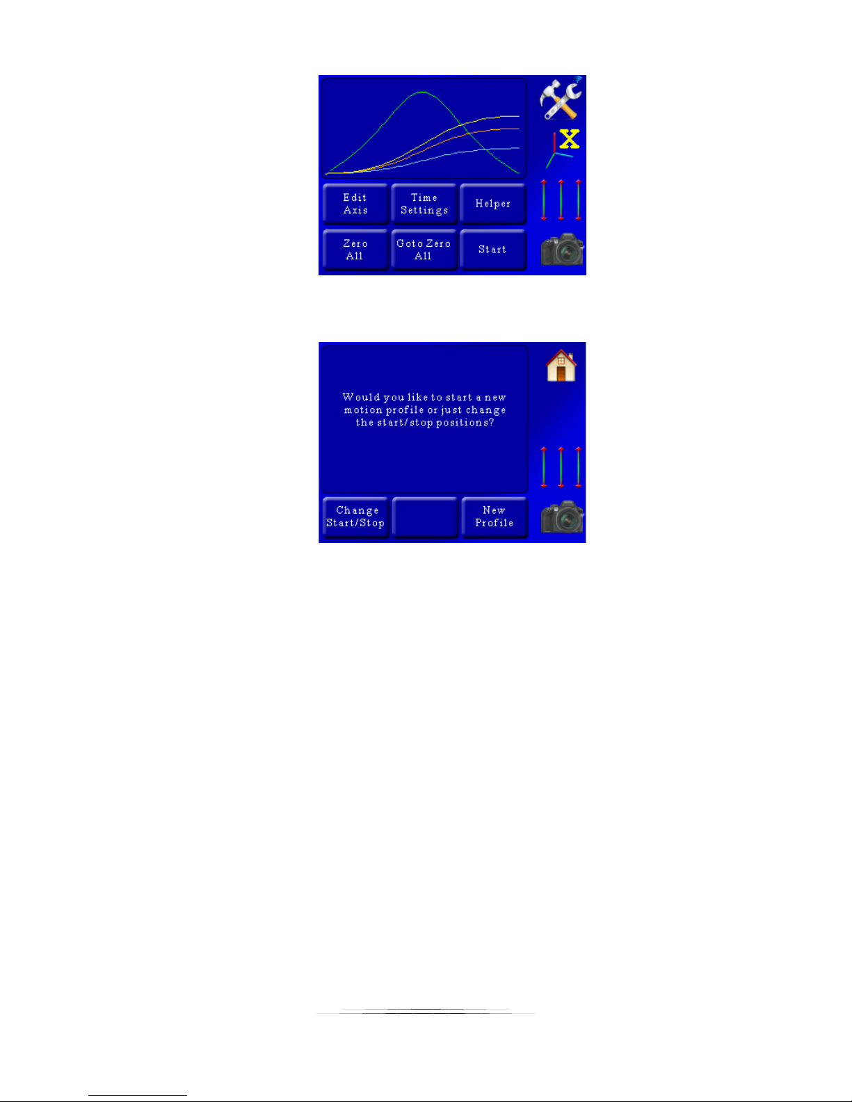
So what happens if you want to just change the start and end points now? Do you have to go
through all of that over again? No! The next time you press “Helper” you will see:
If you choose “New Profile” you will start from the beginning of the helper screen like above. If,
however, you press “Change Start/Stop” you will just be asked for the new start and end
positions – skipping the rest of the questions. That speeds things up if you run the motion
profile or do a preview and find something is just a bit off – you can easily change it here.
7.3.2 Shoot-Move-Shoot
The helper for “Shoot-Move-Shoot” is nearly identical to the real-time video helper with the
exception of a few questions at the beginning:
66
Page 67
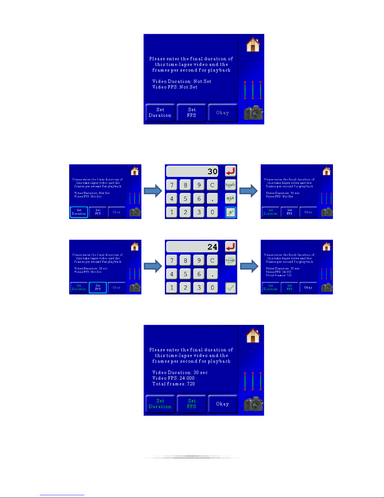
You will need to enter the final duration (playback duration) and the frames per second. This
will calculate the number of frames required. For this example we’ll set the duration to 30
seconds (of playback), and have the frames per second (FPS) set to 24:
You’ll see a summary once both the duration and FPS are set:
Here you can see in this example a total of 720 frames will be required to get a 30 second video
at 24 frames per second. If you would like to continue press the “Okay” button. You can also
67
Page 68
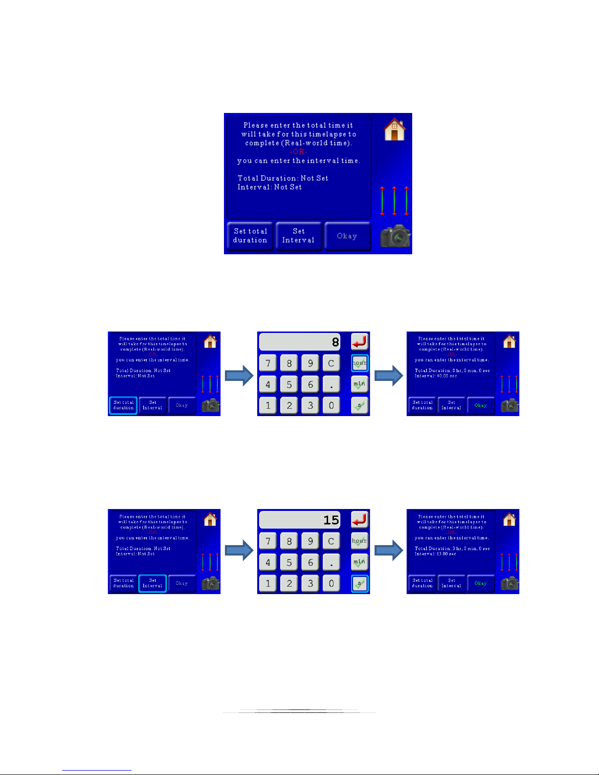
change either the duration or the frames per second if you’re not happy with the total number
of frames.
Once you press “Okay” you will now be asked for the total duration or interval:
You only have to set one of these. The “Total Duration” is used when you know how long you
would like to run the time lapse over. This is usually a long time (hours) since it is “Real-world”
time. So if you would like the time lapse to run over 8 hours you would press:
StackShot 3X will calculate what the interval time should be, which in this case is 40 seconds.
Sometimes you don’t care how long the time lapse video will take but you do know how often
you would like it to take a photograph. In this case, press the “Set Interval” button and enter
the interval between frames:
In this example, we set the interval (time between frames) to 15 seconds. This gives a total
“Real-world” time of three hours.
If you enter a time that is too fast you will see a warning that the time will be adjusted. If you
don’t want it adjusted you are given the option to go back and change the “Video Duration” or
“FPS”.
68
Page 69
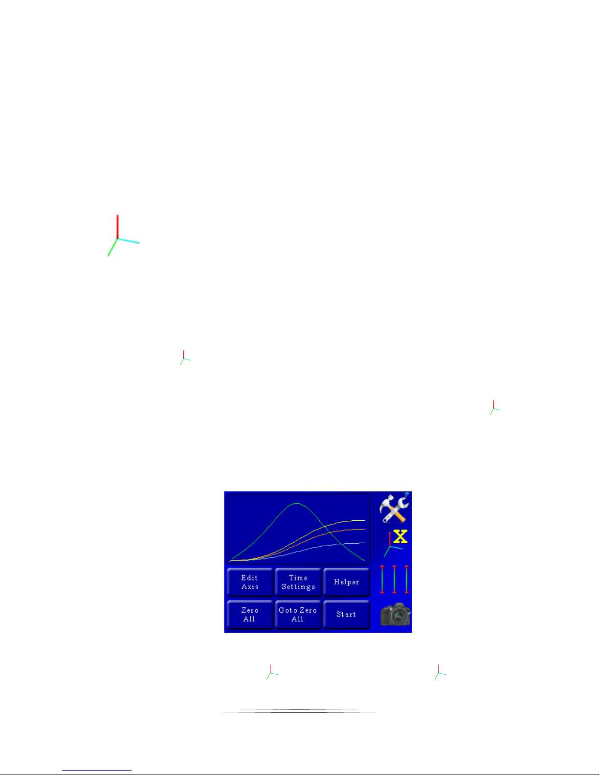
If everything looks good then you can press the “Okay” button.
From this point the process is exactly the same as section “7.3.1 - Video: Continuous”. You will
be prompted for the profile type, what is connected, and the start/end positions.
7.4 Changing Axes
In the above screen you can see all three axes motion profile. They are color-coded. Below the
settings tab you see the three-axis indicator:
With a colored “X” next to it. The color of the “X” corresponds to the colored line on the curve.
The color-coding is as follows:
Yellow: X-axis
Orange: Y-Axis
Blue: Z-axis
If you press the button, it will cycle through all three axes and change the color of the axis
indicator.
If you want to disable an axis from running you can do that by pressing and holding the
button. It will gray out just that axis and it won’t run when you press the “Start” button.
7.5 Velocity Curve
You’ll notice a green curve in the plot window:
This is the “Velocity” curve, or speed curve for that axis. In the above example the green curve
is the speed for the X-axis, since the button shows “X”. If you press the button, the green
curve will change and reflect the velocity for the next axis. You’ll see that the bottom of the
69
Page 70
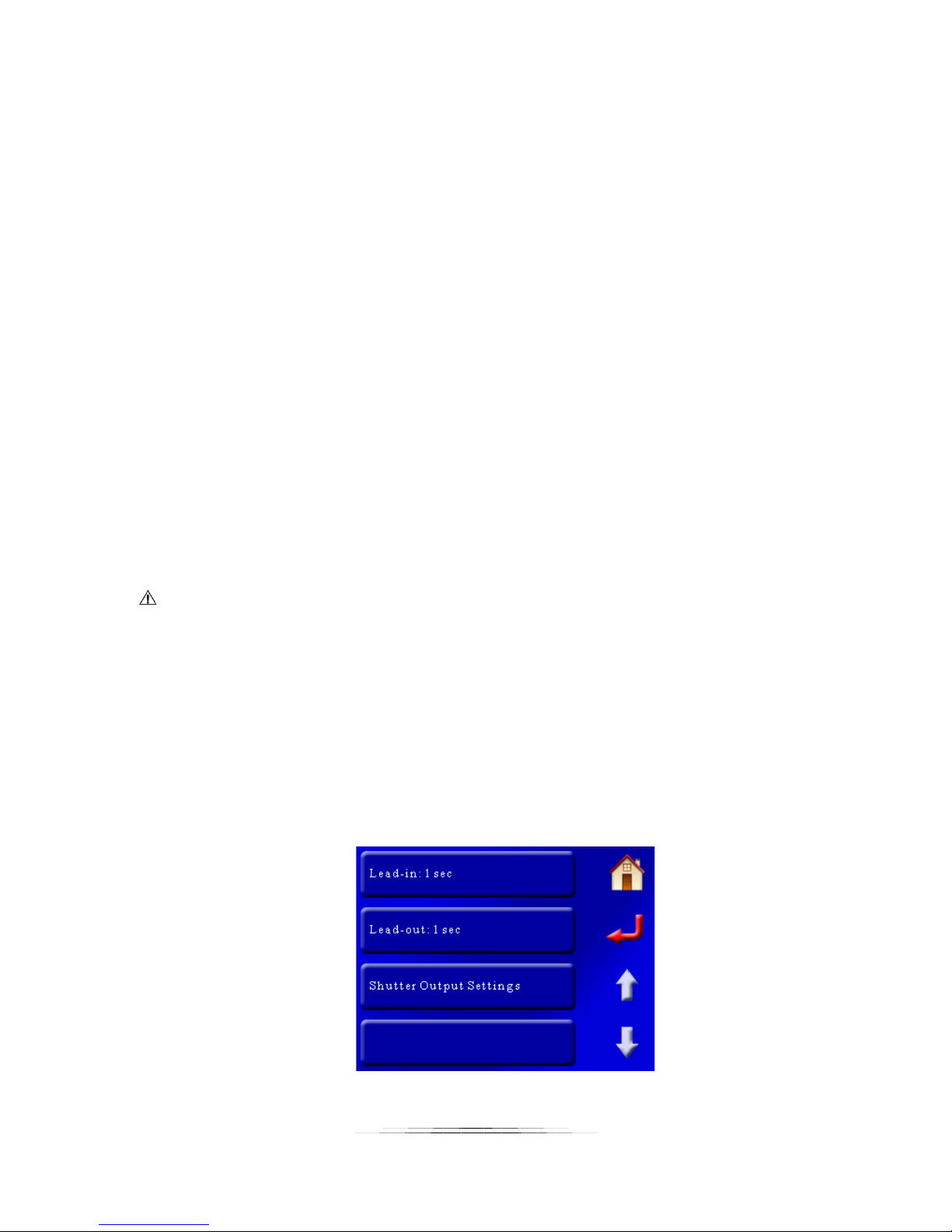
plot window is zero, which makes sense for this plot. The motor is going to start at speed zero.
You can see that the speed curve is highest in the middle – meaning that the speed is fastest in
the middle. Since we chose “Smooth start and finish”, this speed profile is expected. It starts
off slow, gets faster in the middle, and then slows down at the end.
If you see the velocity curve turn red at any point there is a problem with the move profile you
have programmed. The “Start” button will also turn red. The reason the curve and start button
turn red is to indicate that the velocity at that point exceeds the maximum allowed velocity.
The rotary table or slider just can’t move that fast in the time-frame you provided (like trying to
move a full meter in two seconds).
What happens if you press the start button when it is red? The controller will move along until
it hits the red portion and then the velocity will remain at the maximum for the duration it is in
the red section. Since it can’t hit the target speed it will end up not moving as far as you
wanted. That isn’t always a problem but there is one condition where this can cause serious
issues and camera equipment damage. Let’s say you have the camera tilt up too fast, and then
slowly tilt down. In this case the controller won’t be able to tilt the camera up to your target
position because it has reached maximum velocity. It can, however, tilt it back down slowly.
The net result is that it won’t go as high as you wanted but can go lower. This could potentially
cause camera equipment damage.
CAUTION: If you see the red velocity curve and/or the red “Start” button you should verify that
camera equipment damage won’t occur.
7.6 Time Settings
The units of time in “Video: Continuous” and “Video: Timelapse” is in seconds. For “Timelapse:
Shoot-move-shoot” seconds don’t really apply. Frames, however, do! So “Time” is in seconds
for all modes except for “Shoot-move-shoot”, which is in frames. The time settings screen
changes slightly if you’re in “Video: Continuous” mode or “Shoot-move-Shoot”. They are,
however, similar. Here is the “Video: Continuous” screen:
70
Page 71
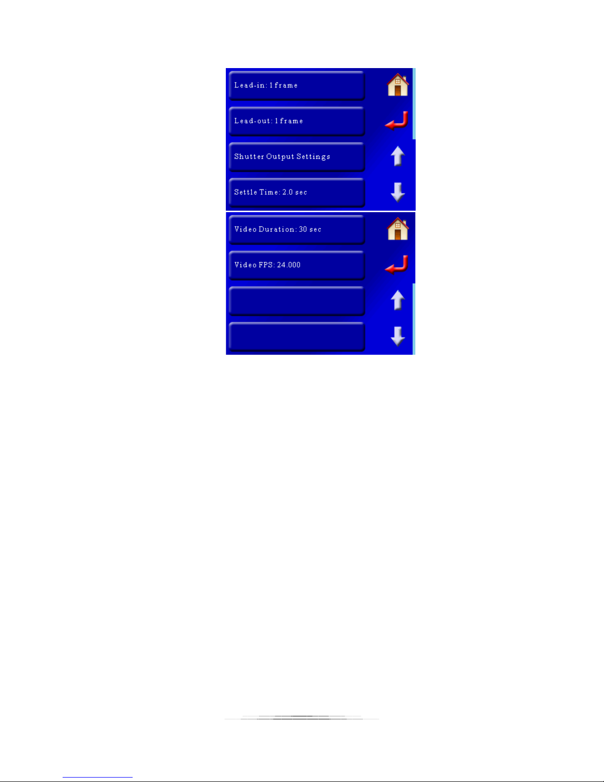
And here is the “Shoot-Move-Shoot” screen (two pages):
7.6.1 Lead-In
“Lead-In” is the time that will elapse before the motors start following their motion profile. For
video mode, the shutter will activate and then wait this duration before starting to move. For
“Shoot-Move-Shoot” this is the number of frames to take before the motor(s) start. For time
lapse applications this is a great visual effect to collect a number of frames prior to the
equipment following a motion profile. You can set this to zero if desired.
7.6.2 Lead-Out
You guessed it! This occurs after the move is complete. Again, it is a nice effect. You can also
set this value to zero.
7.6.3 Shutter Output Settings
This lets you adjust any of the shutter output settings (on time, off time, number of activations,
etc). It is discussed further in section “8.5 – Shutter Output Settings“.
Note: The helper will adjust these settings when in “Shoot-Move-Shoot” mode to set the
proper timing between frames. If you edit these settings after using the helper you will change
the final timing of your motion profile.
7.6.4 Settle Time (SMS Only)
This sets how long after the motors move before a picture is taken. It allows time for system
and mounting vibration to stop to prevent motion blur.
71
Page 72

Note: The helper will adjust these settings when in “Shoot-Move-Shoot” mode to set the proper
timing between frames. If you edit these settings after using the helper you will change the final
timing of your motion profile.
7.6.5 Video Duration (SMS Only)
This configuration sets how long your final video (playback) duration will be. StackShot 3X uses
this and the frame-rate to determine how many frames you will need to meet this duration.
Note: The helper will adjust these settings when in “Shoot-Move-Shoot” mode to set the proper
number of frames. If you edit these settings after using the helper you will change the final
timing of your motion profile.
7.6.6 Video FPS (SMS Only)
This is the playback frames-per-second. StackShot 3X uses this to determine the number of
frames required for the specified duration. Total number of frames = Video Duration x Video
FPS.
Note: The helper will adjust these settings when in “Shoot-Move-Shoot” mode to set the proper
number of frames. If you edit these settings after using the helper you will change the final
timing of your motion profile.
7.7 Zero All
Pressing the “Zero All” button will use the current position of all the motors as the beginning of
the motion profile (setting the home position). This is useful if you want to keep the same
motion profile but just change the starting points for all axes. You could go through the helper
all over again or you could adjust the motors using the 3-axis slider:
button. After adjusting the position, press the “Zero All”. You will be asked to confirm this
change since it will overwrite your current starting position.
7.8 Goto Zero All
This will return all of the enabled axes to their zero (or home) position. When returning to the
zero position the motors will not follow the motion profile – they’ll get back there in a hurry!
If you plan on using the same equipment setup but will have to disconnect power from
StackShot 3X, it is a good idea to send all the motors to their zero (home) position first. The
reason: If you finish a motion profile and then remove power, the controller will use that final
72
Page 73
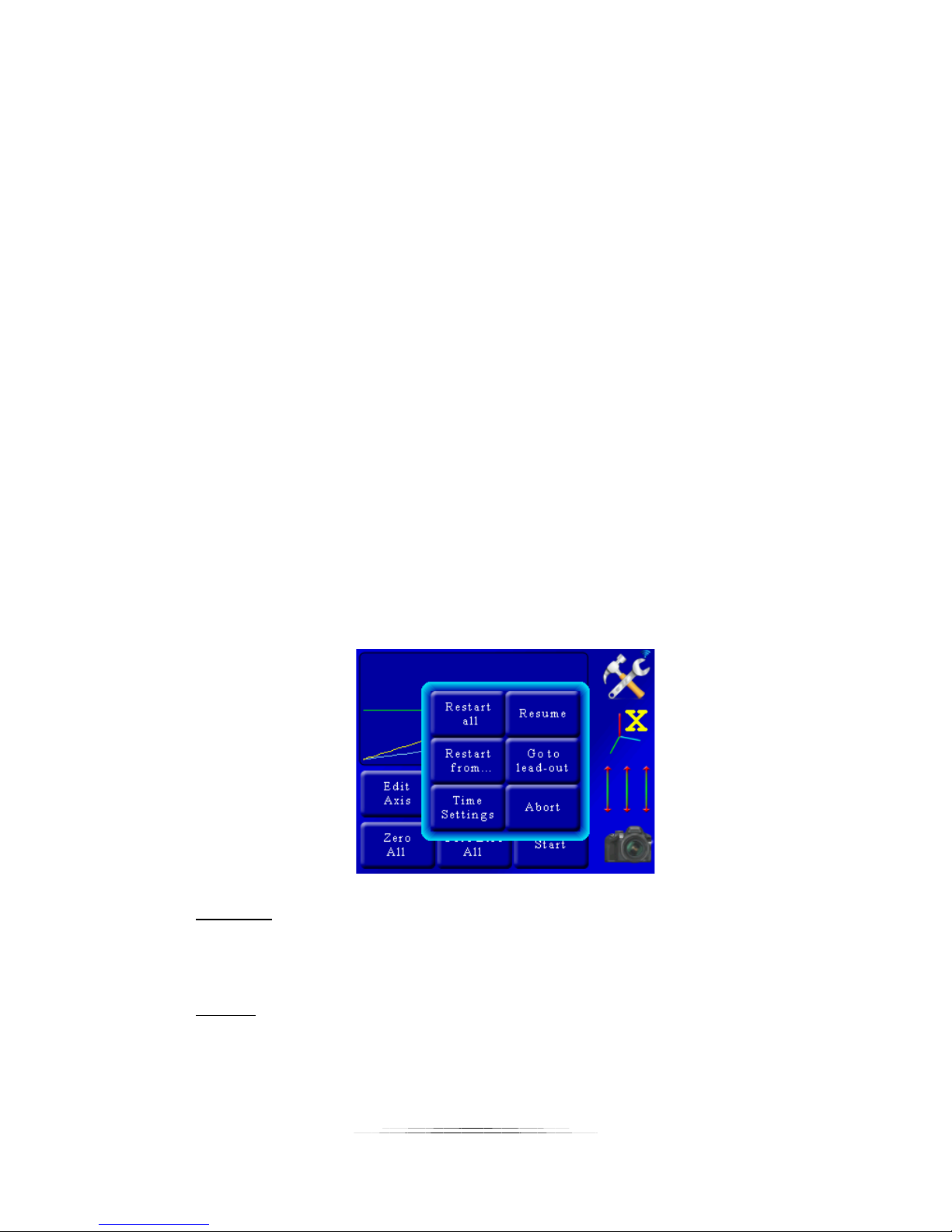
position as its starting point for the next time power is applied. That could cause equipment
damage if you just plug in power and hit the start button again. Ouch!
7.9 Start (and Preview)
This button starts the motion profile. If the motors are not at their zero position you will be
asked if it is okay to return back to zero.
For “Shoot-Move-Shoot” mode the “Start” button has an additional feature. So you have your
time lapse set up to run over an eight-hour period. It’s not terribly easy to check your framing
just by looking at the first and last frame – trouble can be lurking in the middle of your shoot
somewhere that you might not find until after the eight-hours while processing the frames.
Nuts! We’ve been there before. StackShot 3X has an excellent preview function. If your final
video duration is set to 30 seconds (as an example), you can press and hold the “Start” button
and get a real-time motion preview of the move (which would be 30 seconds of move-time).
Ideally you would use live-view on your camera and record a video. This short and simple step
could save you a night (and 1000 frames!) of wasted effort. If StackShot 3X can’t run the profile
because it exceeds the maximum speed for an axis the real-time motion will last slightly longer.
7.10 Abort Screen – Shoot-Move-Shoot only
If you’re running a lengthy time lapse you may find part way through that there is a problem. If
you touch the screen it will abort the current time lapse and show a pop-up asking what you
would like to do from this point:
Restart All:
This option will restart the current time lapse from the beginning. The motors will return to
their starting position and start with the lead-in.
Resume:
If you accidentally touched the display and didn’t intend on aborting the time lapse then you
had better press the resume button. Depending on when it was aborted you may end up
73
Page 74

with a duplicate frame at this position. This is also a good way to temporarily pause your
time lapse.
Restart from…:
If you would like to start the time lapse over at a specific frame you can press this button
and then enter the specific frame number. The time lapse will continue from that frame
until the end.
Go to lead-out:
Press this button to just start shooting the lead-out frames from this current position.
StackShot 3X won’t go to the end position – it will just start shooting the lead-outs from the
current position. This is useful when you’ve realized you’ve moved too far, the sun is
rising/setting, or something else is going on that will certainly ruin the rest of your time
lapse – grab the lead-out and finish up.
Time Settings:
If you want to adjust the shutter parameters or motor settling time on the fly you can do it
here. This could overwrite settings that the helper calculated for you and change the total
duration of the video. When would you use this? Here is an example of camera trouble: If
your using aperture priority on your camera and find out what you *thought* was going to
be your longest exposure is now going to run too long. You can quickly abort the move,
press the time settings, and then adjust your “Off Time” to compensate for it. See section
“8.5 - Shutter Output Settings” for details on adjusting the shutter parameters.
Abort:
Press this button if you really did intend on aborting the time lapse. We want to make sure
you really REALLY wanted to abort! Touching outside of the pop-up will also abort the time
lapse.
7.11 Edit Axis
We strongly encourage you to use the helper to set up your motion profile. The “Edit Axis”
button should be reserved for advanced users. You can do some really neat stuff under here
but also make a mess in a hurry! If you *do* wreck your motion profile you can always go back
to the helper to get things set right. If you are finished editing the axis or got here by mistake
just press the “Home” button to get back to the main motion screen.
The “Edit Axis” button lets you adjust settings for each individual axis. The motion profile is
determined by key frames. What is a key frame? It means, “At time ‘X’ I want the motor to be
at position ‘Y’ “.
74
Page 75
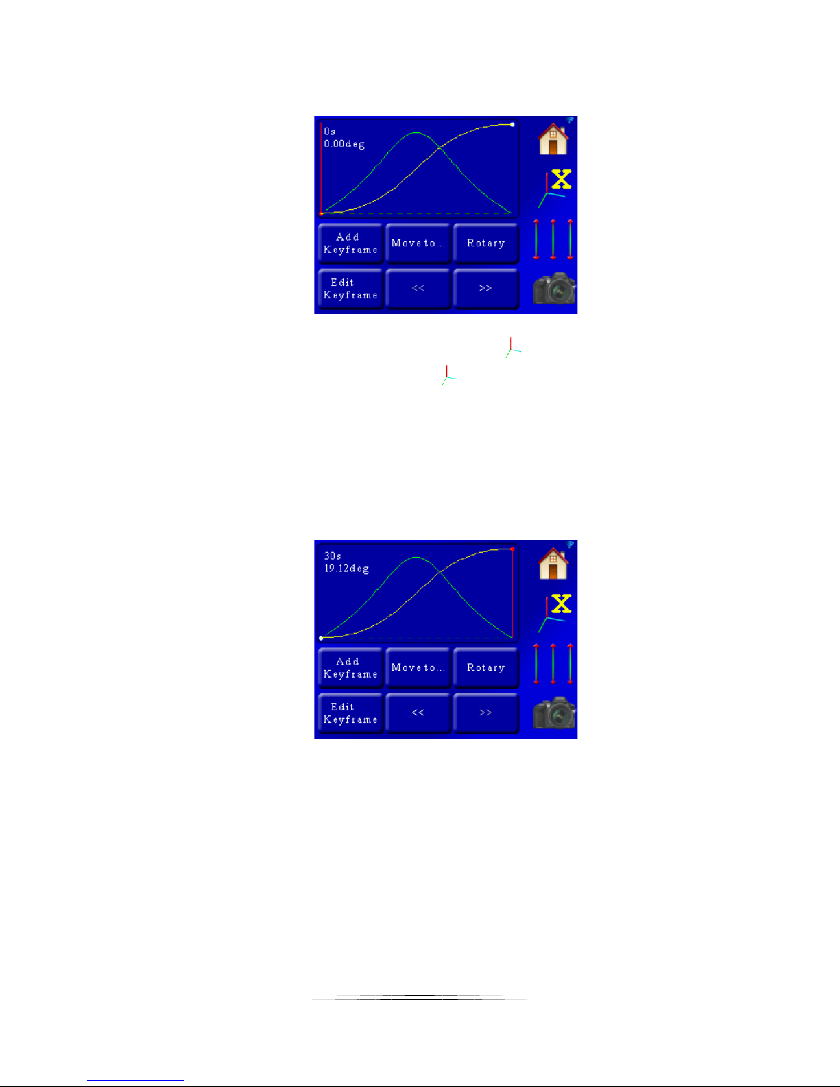
Using the same examples used previously, if we press the “Edit Axis” button we will see this
screen:
Here we only see the motion profile for a single axis. The button shows that we are
currently looking at the X-axis. If you press the button you can cycle through all three.
In the plot window you see the yellow line (which is the motor position vs. time) and the green
line (velocity/speed – see section “7.5 – Velocity Curve“). You’ll also see a vertical red line that
has “0s 0.00 deg” next to it. That is the time and position for the current key frame. In this
example we only have two key frames – which is plenty to define a nice smooth motion profile.
To move from one key frame to the other press the “<<” or “>>” buttons. Let’s take a look at
what is on the screen when we go to the final key frame:
Since we’re in “Video: Continuous” mode, the time units are in seconds (you would see frames
instead of seconds for “Shoot-Move-Shoot” mode). As you can see the screen shows that at 30
seconds the X-axis will have moved a positive 19.12 degrees.
7.11.1 Rotary / Rail / Slider
This button changes what is connected to this axis. In the above example you can see that a
rotary table is connected. Pressing this button cycles through the different types of gear that
75
Page 76
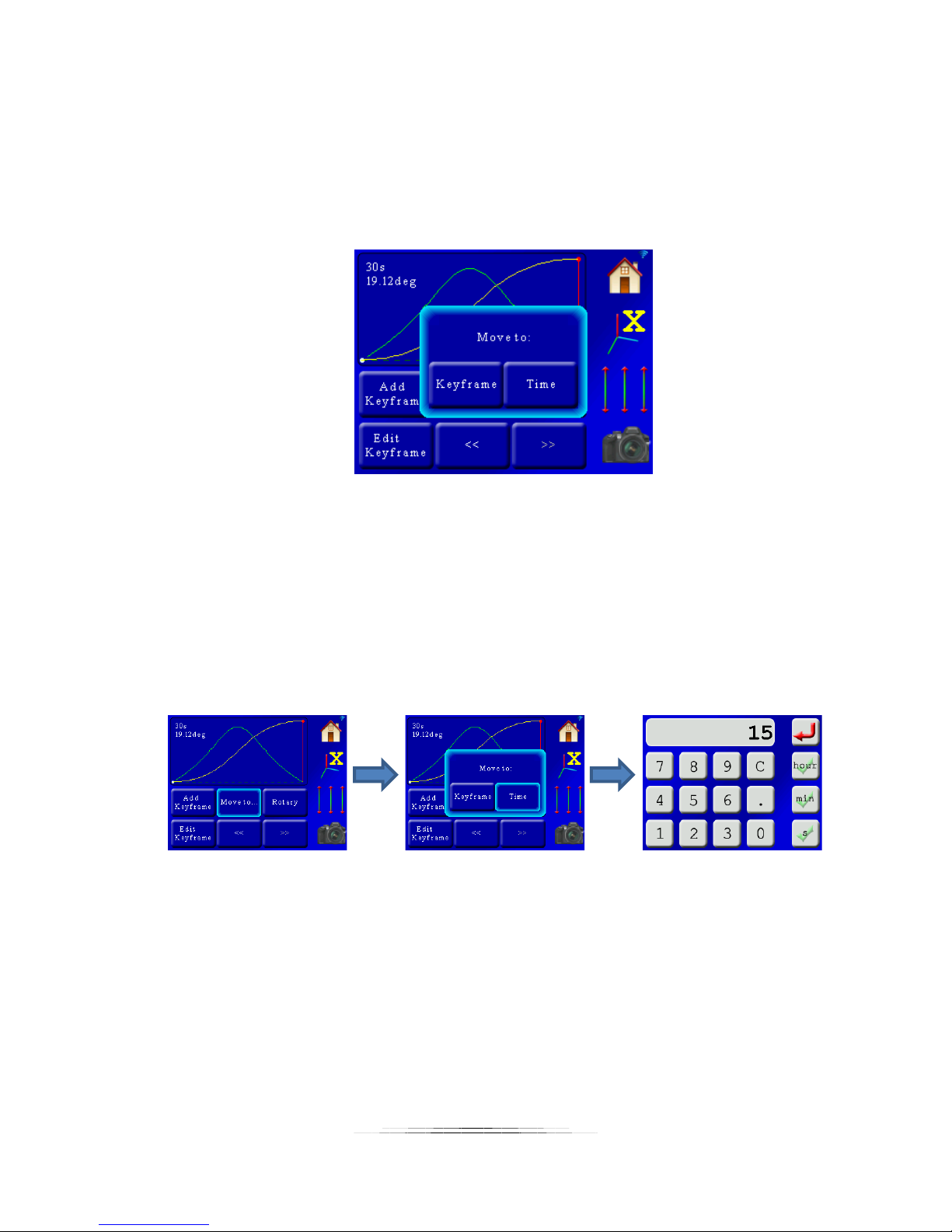
can be attached to StackShot 3X. Why does it matter? A rotary table, rail, and slider have
different parameters (speed, torque, etc). They are initially set by the helper.
7.11.2 Move to…
Pressing the “Move to…” button brings up a pop-up window with two options:
The two options are “Keyframe” and “Time”. If you choose “Keyframe”, the controller will move
all three axes to the key frame currently selected (the red vertical line). In this case we only
have two key frames – the beginning and the end of the profile. If we want to get somewhere in
between we can use the “Time” button. This will let you move to any time between the
beginning and end point. You just have to enter the time desired. The process would go like
this: Press the “Move to…” button, then the “Time” button, enter the desired time, and away
the motors go! For “Shoot-Move-Shoot” you would enter the frames instead of time.
In this case, we moved to 15 seconds (or frames) into the move profile. All three axes are
positioned exactly where they would be after 15 seconds. The screen is updated and the red
indicator shows the current position.
Why would you want to move to a specific time? First, it can be nice to double-check framing.
Secondly, it makes it easy to add a key frame at that point.
76
Page 77
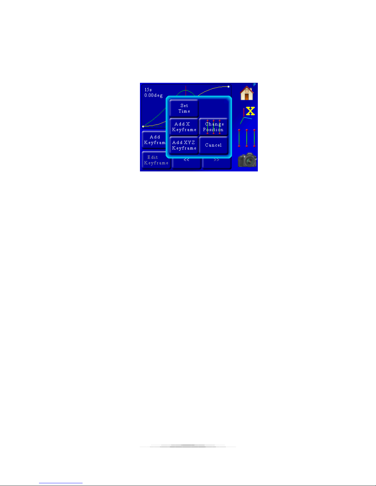
7.11.3 Add Key frame
StackShot 3X supports up to five key frames per axis.
Pressing the “Add keyframe” button brings up a pop-up window asking for some additional
information:
Here we have a few additional buttons:
7.11.3.1 Set Time / Set Frame
This is an optional setting. In the previous example of using the “Move to…” to move us to a
specific time, the indicator shows we’re already at 15 seconds. If, however, you want to add a
key frame at a different time (or frame number) you would press the “Set Time” (or “Set
Frame”) button. The controller would then ask you for the time or frame for this new key
frame.
7.11.3.2 Add X / Y / Z key frame
This will add a key frame at the current motor position for just the current axis. If you want to
add a key frame at a different position then you will need to press the “Change Position” button
within this pop-up window, adjust the motor position as necessary, and then press the “Add X
keyframe” button.
7.11.3.3 Add XYZ Key frame
This button will add a key frame for all three axes at the current time/frame setting. Make sure
that all the other axes are at your desired position before pressing this button. If the position is
not correct, use the “Change Position” button within the pop-up to make adjustments.
7.11.3.4 Change Position
This will bring up the 3-axis slider to adjust the motor positions as necessary. Don’t press the 3axis slider outside the pop-up window on the right-hand side of the screen – it will dismiss the
pop-up.
77
Page 78
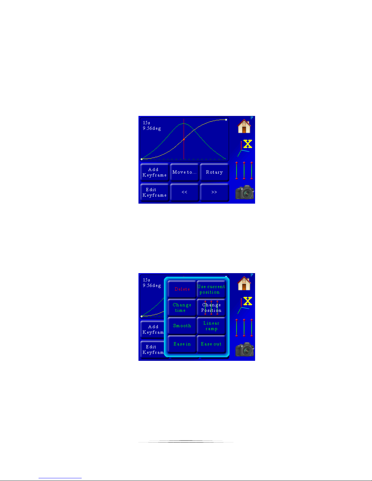
7.11.4 Edit Key frame
This button lets you edit a specific key frame. Use the “<<” and “>>” buttons to select the key
frame you would like to edit.
Continuing with our example, we added a key frame at 15 seconds by doing:
“Move To…”->15 seconds
“Add Keyframe”->”Add X Keyframe”
Those steps added a key frame at 15 seconds:
You can see the red circle and red line showing the active key frame. As you recall, our total
movement (the key frame on the right) was 19.12 degrees. By adding a key frame half way
through the motion profile we see that the position is 9.56 degrees. Nice! Half-way through the
time of the move and half the position – the math is good! Now let us see what happens when
we press “Edit Keyframe”. Since the red vertical line indicates the currently selected key frame,
that is the key frame we will be editing:
If you decide you don’t want to edit a key frame just press any portion off of the edit pop-up
window to dismiss it.
78
Page 79
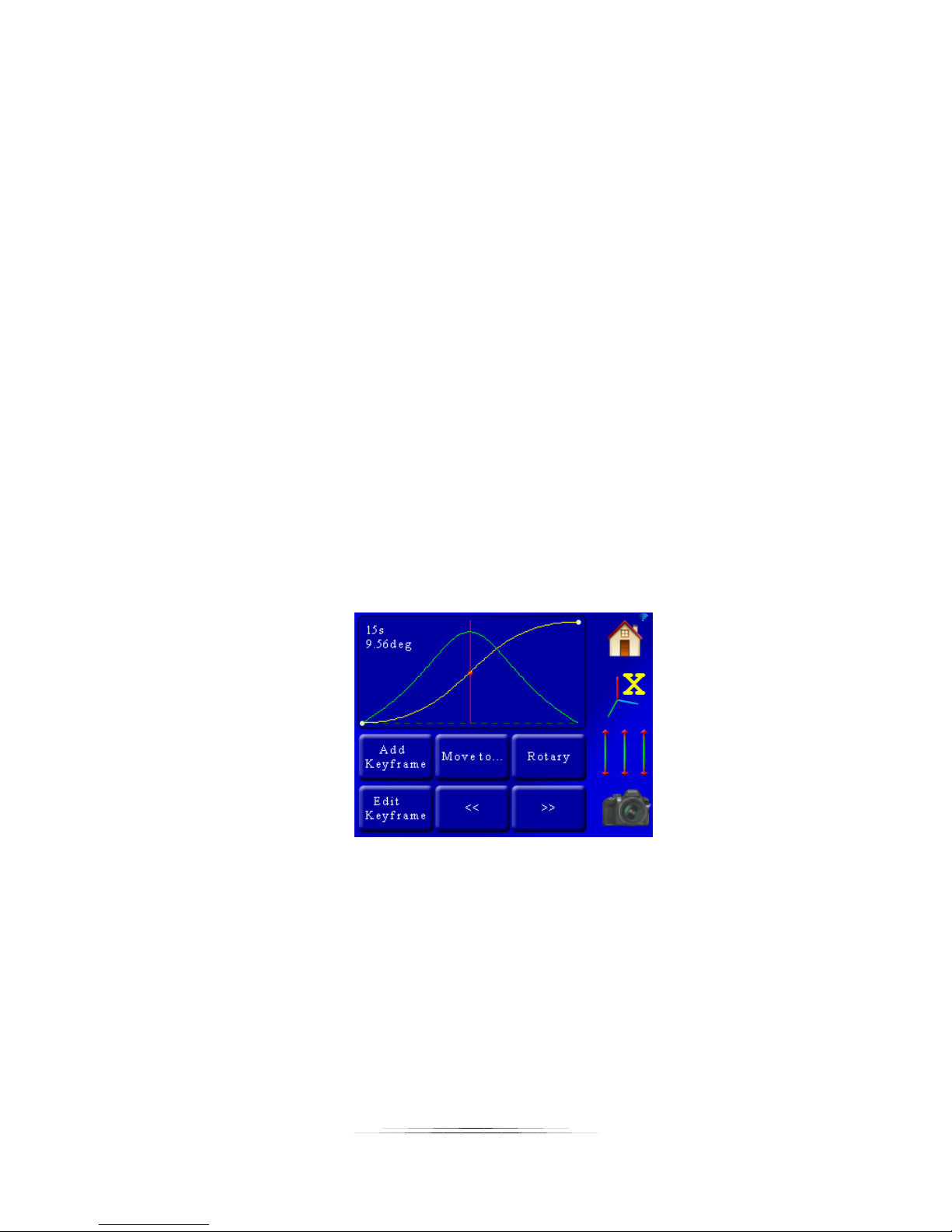
7.11.4.1 Delete
This will delete the currently selected key frame. This is only available if the number of key
frames is larger than two.
7.11.4.2 Change Position
This will bring up the three-axis sliders for adjusting the position of the motor. After you change
the position and return to this pop-up screen you will need to confirm your new position by
pressing the “Use Current Position” button.
7.11.4.3 Use Current Position
After changing the motor’s position using the “Change Position” button, pressing “Use Current
Position” will update the key frames position with the new position and return you back to the
curve screen.
7.11.4.4 Change Time / Change Frame
Here you can edit what time or frame number for this key frame. By doing this you will expand
or contract the total length of your motion profile (it won’t change the time between other key
frames).
7.11.4.5 Smooth
Smoothing a key frame means that the speed entering this key frame will try and match the
speed leaving the key frame. This creates a smooth motion. The example below is of a smooth
key frame:
7.11.4.6 Linear Ramp
A linear ramp keeps the velocity constant going into and out of the key frame. It won’t stay that
way though the further you get away from the key frame since the key before and after this key
frame will start to influence the motion profile. This is what it looks like setting the above
middle key frame to linear. Note how it has a straight-line velocity going into and out of the key
frame. Sharp-edge transitions like shown below will cause a noticeable change in velocity:
79
Page 80
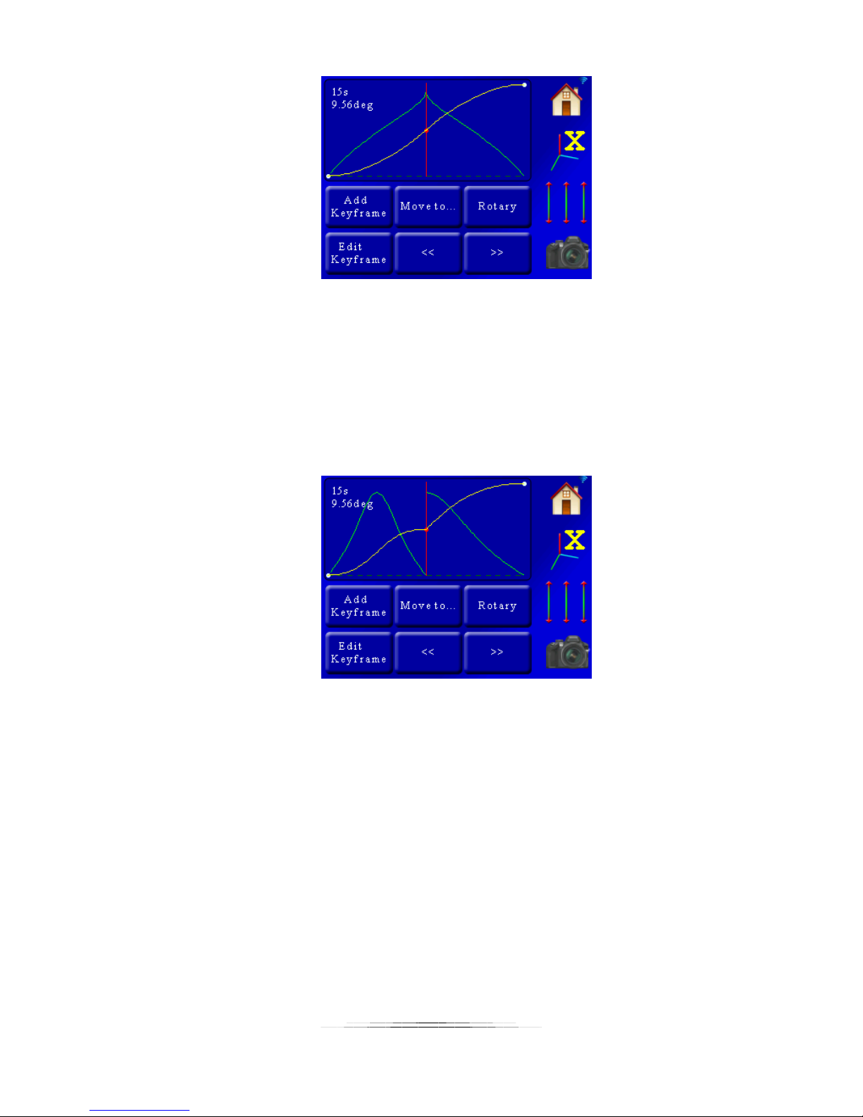
7.11.4.7 Ease In
“Ease In” means the velocity will decrease to zero going into the key frame (on the left side).
This is a great way to stop the motion part way through a frame. Since it will only apply to the
left side you can get a sharp change in velocity at the key frame. Normally you would “Ease In”
and “Ease Out” of a key frame. Here is an example of the middle key frame starting off
“Smoothed” and then being told to “Ease In”:
As you can see the velocity drops to zero as it approaches the key frame and then immediately
takes off exiting it. Because the velocity going into the key frame is zero and the velocity leaving
it is quite high you would get a “jerk” in the motion here.
7.11.4.8 Ease Out
“Ease Out” is the counter-part to “Ease In”. Here is a plot of a smoothed curve with the middle
key frame set to “Ease Out”:
80
Page 81
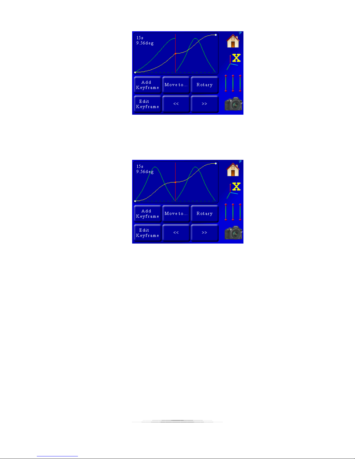
It looks like a mirror of the “Ease In” setup.
Now let’s look at what happens when we apply an “Ease In” and “Ease Out” to the same key
frame:
That looks neat – but what does it do? And what is up with the “M” shape for velocity? This is a
pretty useful motion profile. The motor will start off slow, speed up, but as it approaches the
center of the profile it will slow down and pause briefly, before speeding up and then slowing
down at the end. This is exactly what the helper’s “Slow at center” option does.
7.12 Dragon Frame DfMoco
Dragon Frame by DZED Systems is an excellent program for Shoot-Move-Shoot motion control.
StackShot 3X is compatible with Dragon Frame when you select the “DragonFrame – DfMoco”
mode. Once in this mode the screen will show “DfMoco”. At this point StackShot 3X must be
controlled by your computer. To exit the “DfMoco” mode, touch the screen and select a
different operating mode. When in “DfMoco” mode, you will not be able to use focus stacking
programs to communicate with the controller.
Please reference the Dragon Frame owner’s manual for instructions on how to create motion
profiles using their “Arc Motion Control” software.
81
Page 82
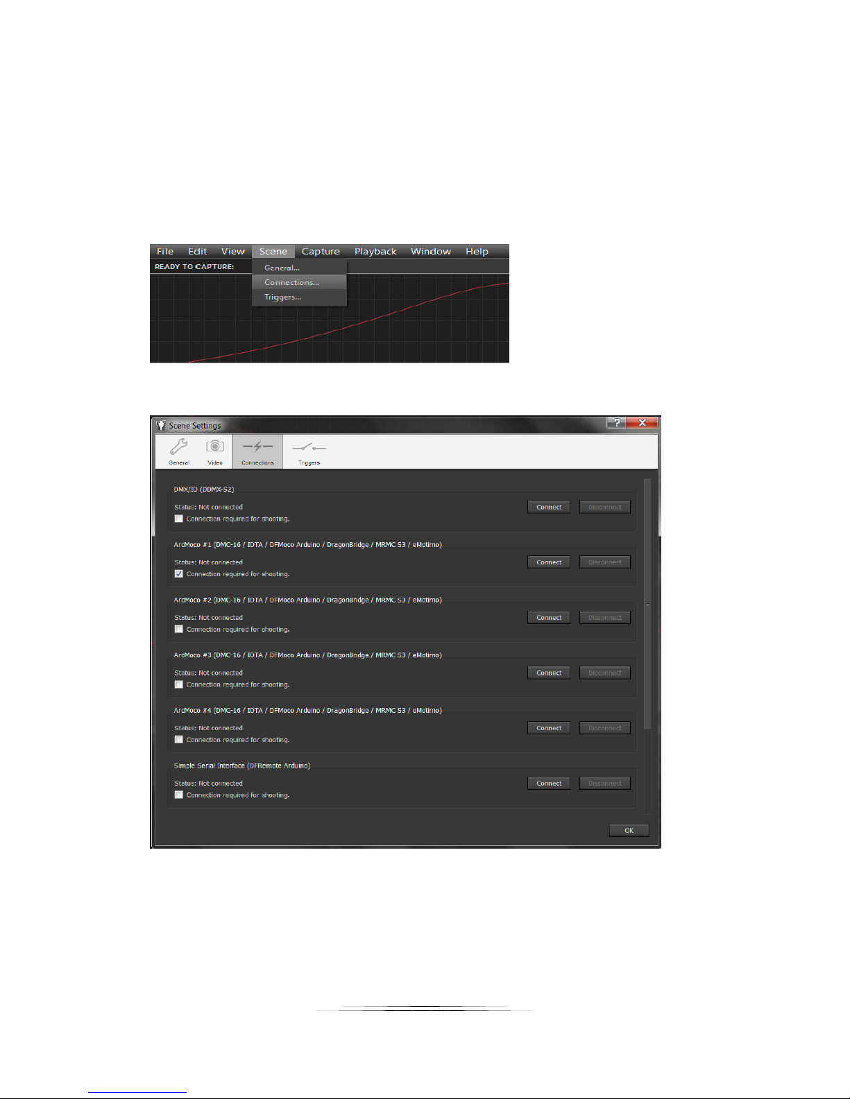
#1
#2
7.12.1 Dragon Frame connecting to StackShot 3X
The first step in using Dragon Frame is to set up the software to communicate with StackShot
3X.
First, click on the “Arc Motion Control” in the upper-right hand corner of the program. This will
bring up the velocity and position graph. Now go to Scene->Connections:
That will bring up the following menu:
1. Make sure that the “Connection required for shooting” check-box beneath “ArcMoco #1” is
checked.
2. Now press the “Connect” button to the right of the “ArcMoco #1”.
You will then see a request for the serial port to use:
82
Page 83
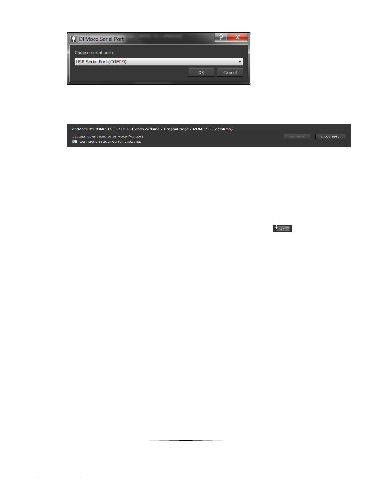
This will depend on other devices connected to your computer. In this case StackShot 3X shows
up as serial port 19. Select the correct serial port and press OK.
You will then see ArcMoco #1 show:
Once connected click the “OK” button at the bottom to close this window.
7.12.2 Configuring the axes
Now that we have Dragon Frame connected to StackShot 3X we need to configure Dragon
Frame for using the Cognisys motorized gear (rotary, rail, and slider).
We will set up one of each in this example. First, click the “add axis” button:
That will bring up the “Configure Axis” screen. We will start with a rotary table.
83
Page 84
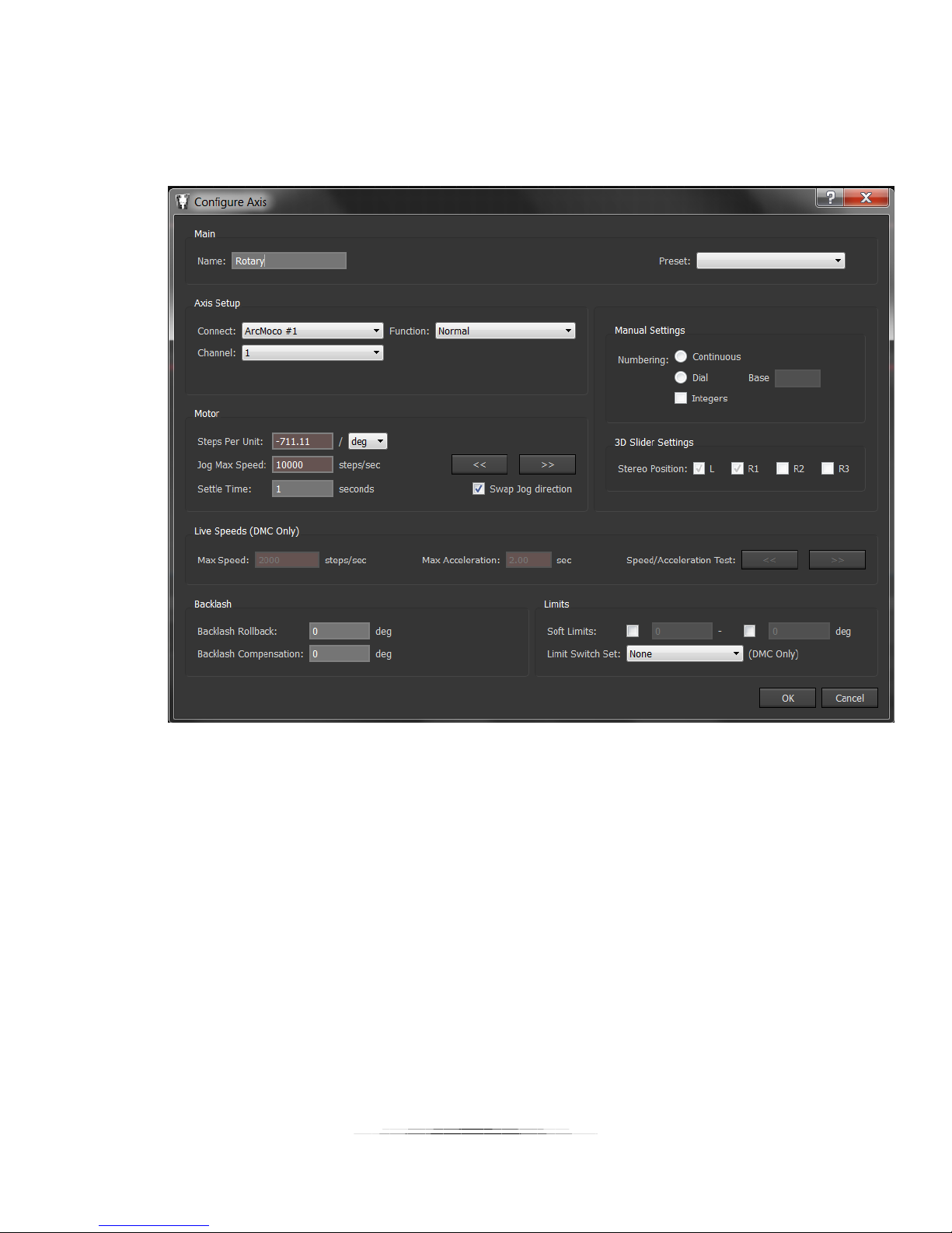
7.12.2.1 Rotary Table Settings
Here are the parameters that need to be changed:
Name: Rotary (or pan/tilt to make things easier to follow)
Connect: Leave at ArcMoco #1
Channel: 1 (This is the X-axis, the first motor available)
Steps Per Unit: -711.11 / deg (Yes, that is a negative in front! Otherwise it will go backward)
Settle Time: Whatever your application requires (one second in this example)
Swap Jog direction: Checked
Press OK!
84
Page 85
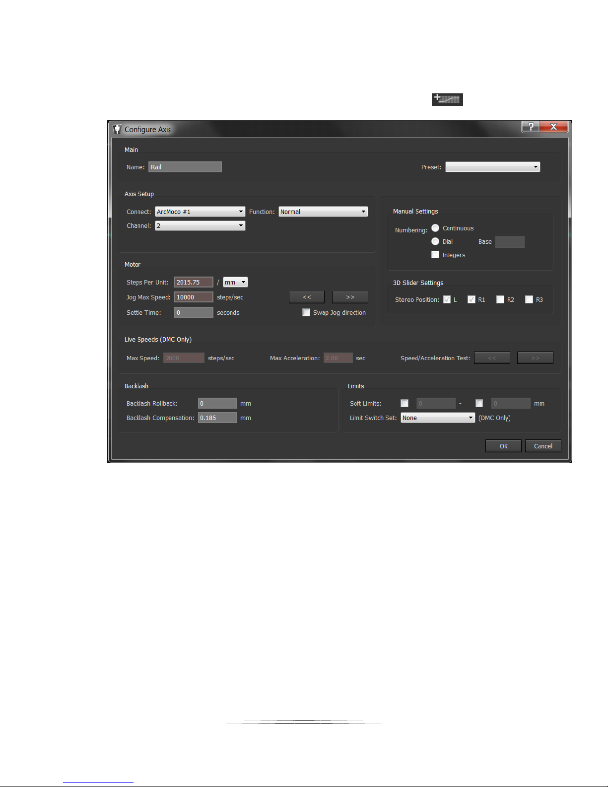
7.12.2.2 Macro-Rail Settings
We’ll add a second axis for the macro-rail by clicking the “Add Axis” icon:
Here are the parameters that need to be changed:
Name: Rail
Connect: Leave at ArcMoco #1
Channel: 2 (This is the Y-axis, the second motor available)
Steps Per Unit: 2015.7480315 / mm
Settle Time: Whatever your application requires
Swap Jog direction: NOT Checked
Backlash Compensation: 0.185 mm
Press OK!
85
Page 86
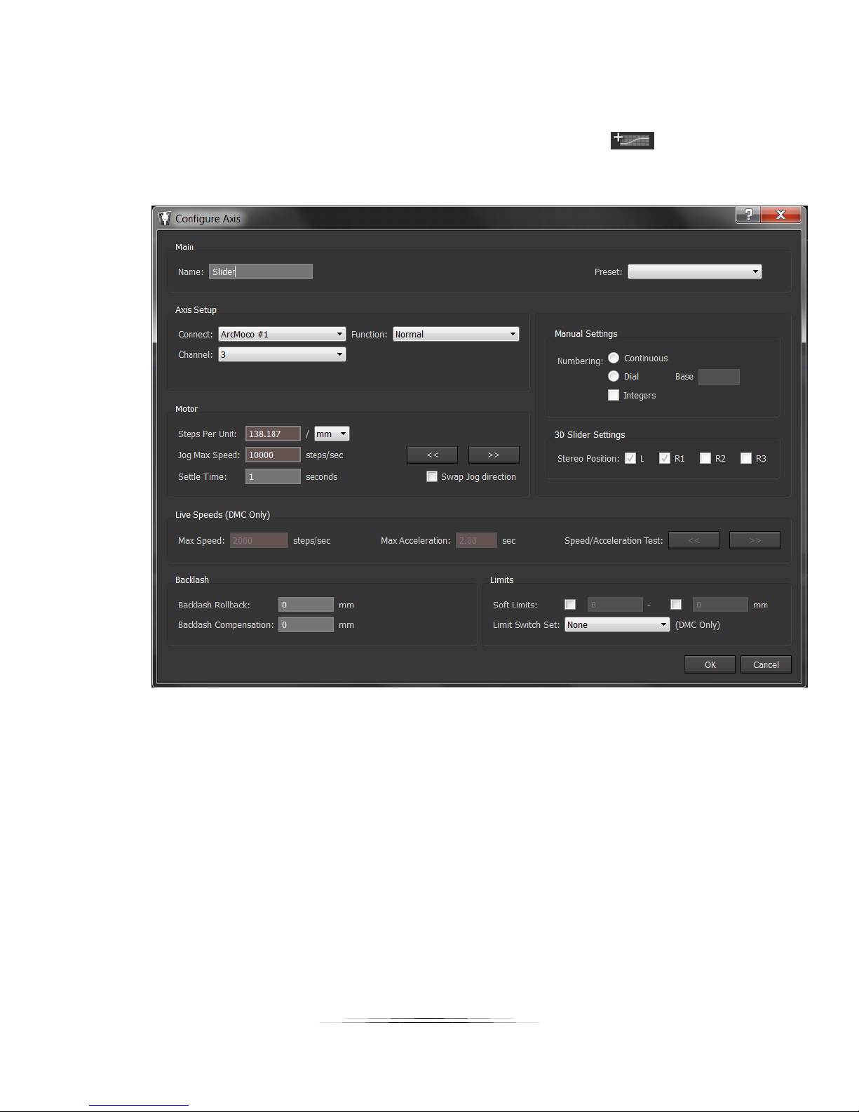
7.12.2.3 Slider Retrofit
Now we will add a third axis for the slider by clicking the “Add Axis” icon:
Here are the parameters that need to be changed:
Name: Slider
Connect: Leave at ArcMoco #1
Channel: 3 (This is the Z-axis, the third motor available)
Steps Per Unit: 138.187296 / mm
Settle Time: Whatever your application requires
Swap Jog direction: NOT Checked
Backlash Compensation: 0.0 mm
Press OK!
86
Page 87
8. Settings
There are several settings that can be adjusted in the StackShot 3X controller to suit your
specific needs. To see or change the settings press the “Settings” icon:
There are several pages of settings. You can scroll through the settings using the Up/down
arrows:
To adjust the settings simply touch the display when you see the setting you need to adjust.
The available settings are discussed below.
8.1 Global Mode
This is the current mode for StackShot 3X. The different modes are discussed in the section “4 Changing Operating Modes”.
8.2 Axis settings
Each axis can have its own unique settings for its function (rail, slider, or rotary table), speed,
settle time, etc. Specific axis settings are discussed in section “9 - Axis Settings”.
8.3 Load/Save Settings
From this menu you can load settings, save settings, or load the factory default settings. There
are eight available “slots” for storing and retrieving your settings.
87
Page 88
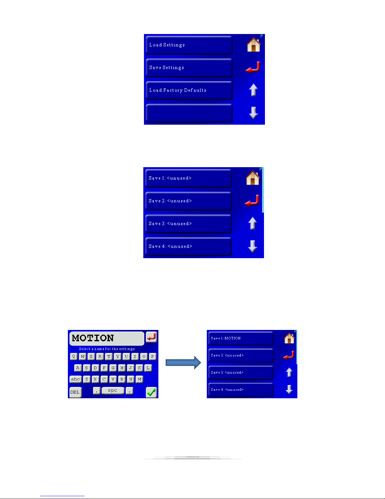
8.3.1 Save Settings
To save your settings, press the “Save Settings” button. This will bring up the following screen:
Here the first four “slots” are shown for storing your settings. Use the arrows to scroll up or
down to the other locations for storing your settings. In this example there are currently no
settings stored. If you had previously stored settings the name for them would be shown. To
save settings in location #1 press the “Save 1” button. That will bring up the QWERTY screen
asking for a name of this setting. We’ll enter “MOTION” for this example and press the green
check-mark:
Press the return button or the home button once you see that your settings are stored.
88
Page 89
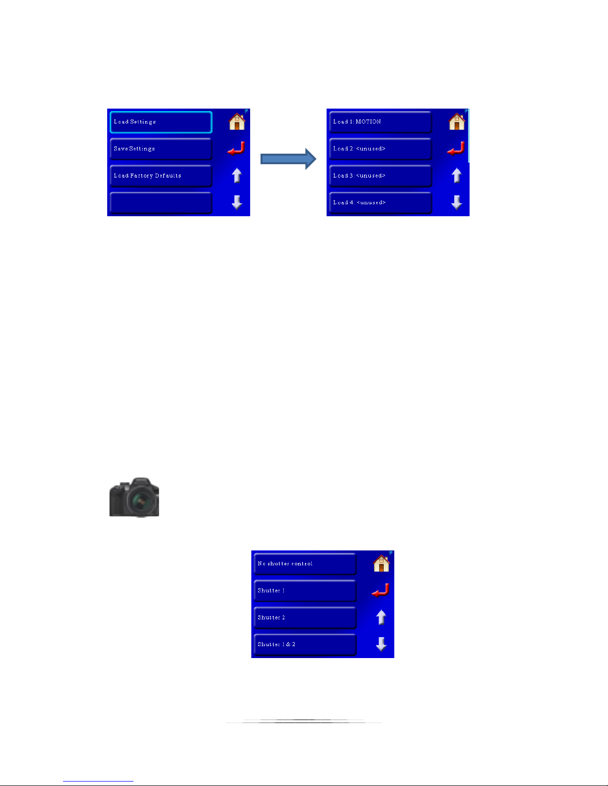
8.3.2 Load Settings
This will load previously saved settings. In this example we’ll show the above saved off
“MOTION” setting:
To load the “MOTION” setting, press the “Load 1: MOTION” button. To exit the load screen
press the return or home button.
8.3.3 Load Factory Defaults
Pressing this button will load the factory defaults for the controller. It will not erase your
previously saved settings – only your current settings.
Note: You can also load the factory defaults another way without using the touch screen. If the
controller is off, press and hold the power button until the red LED goes out. Release the power
button as soon as the red LED goes out. The defaults are now loaded.
8.4 Shutter Button
This setting lets you choose which shutter outputs will activate when you press the shutter
button:
As you can see you have four options:
The default is shutter outputs 1 & 2.
89
Page 90
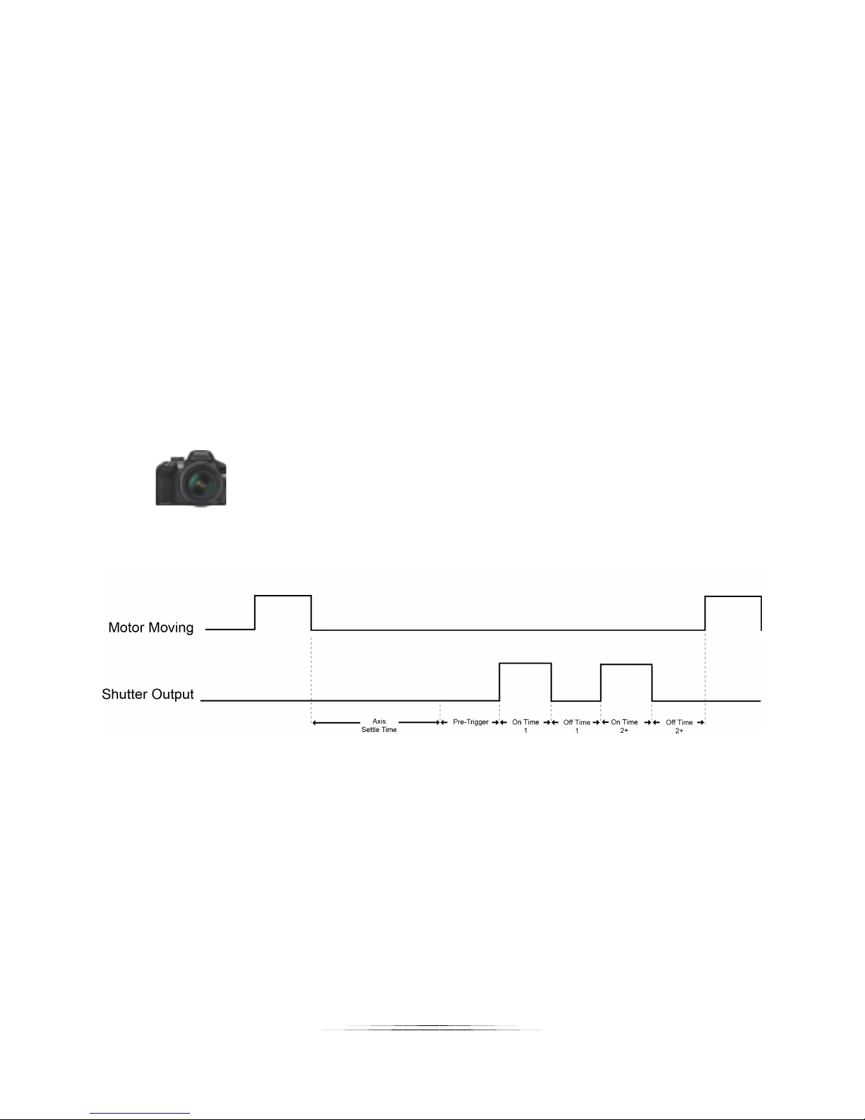
8.5 Shutter Output Settings
Virtually every aspect of the shutter outputs are adjustable. The two shutter outputs can be
independently set – Output 1 can activate multiple times where Output 2 can be set to only
activate once. The settings are quite flexible but need some thorough explaining.
Shutter outputs consist of four parts:
1. Number of times to activate (pics per move)
2. Pre-trigger delay
3. On time
4. Off time
You’ll notice down below that the first and second “on” and “off” times can be adjusted
independently. For those who do a lot of focus stacking with mirror lock-up you may find it
useful to adjust the mirror lock-up time independently from the shutter duration. This can
significantly decrease the duration of a stack.
Any time there is a reference to the “shutter button” it is the camera icon:
The diagram below shows the parts that make up a complete shutter cycle:
8.5.1 Pics Per Move
This is the number of times the shutter output will be activated per motor move or press of the
shutter button. For most applications this will be set to “1”, whereas with mirror lockup you will
want this set to “2”.
Here is an example with “Pics Per Move” set to “3”:
90
Page 91
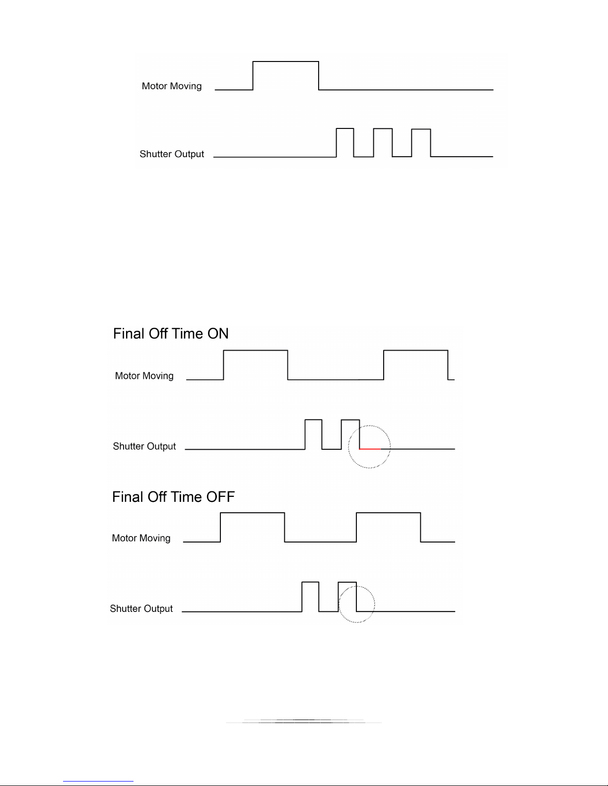
8.5.2 Final Off Time
Each “activation” of the shutter output consists of the time it is on and the time it is off. If you
have more than one “Pics Per Move”, you might not want to wait that final off time.
The default is to wait the final off time.
Below is an example with “Pics Per Move” set to “2”, and showing the difference with “Final Off
Time” set to “Yes” and “No”.
8.5.3 Shutter I/O
Typically the shutter outputs are connected to cameras and set as an output to control when
the cameras should take a photograph. Shutter 1 has the ability to be used as an input. It
91
Page 92
cannot control cameras when set to an input. What can you do with Shutter 1 set as an input?
You can remotely trigger StackShot 3X to begin its current mode (if the current mode is ready to
start). It doesn’t matter if you’re in stacking or motion control mode – If the Shutter 1
connector is shorted to ground it will start (or stop) its current operation. This lets you easily
connect remote cables or devices to the controller for simple operation.
In order to remind you that the shutter is set as an input the shutter icon will change its red
output 1 to a solid blue circle:
8.5.4 Pre-Trigger Delay
The pre-trigger delay is a delay prior to the shutter going active. For Shutter 1 (the RCA
connector) this is purely a delay. For Shutter 2 (the 3.5mm connector) the camera’s half-press
will be activated for this duration.
If the “Pics Per Move” is set to greater than one the pre-trigger delay will only happen prior to
the first activation of the shutter. An example:
Pics per move: 2
Pre-trigger delay: 2.0 seconds
On Time 1: 500 ms
Off Time 1: 500 ms
On Time 2+: 500 ms
Off Time 2+: 500 ms
The shutter would activate the half-press for two seconds, turn the full press on for 500ms, off
for 500ms, on for 500ms, off for 500ms.
The default for this setting is “off”. To set it to “off” enter a duration of zero seconds.
8.5.5 Shutter On/Off Time 1
This determines how long the first activation of a shutter output is on or off. If you have “Pics
Per Move” set to “1” these On and Off times are the only values you have to adjust. If both of
these values are set to “500 ms”, the full-press on your camera would be “pressed” for half a
second, and then released for a half a second before the controller will continue with its next
task.
92
Page 93
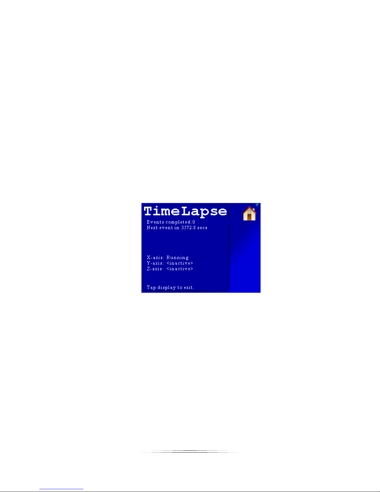
8.5.6 Shutter On/Off Time 2+
If (and only if) the “Pics Per Move” is set to greater than one, this on/off time determines how
long the shutter output will be on or off for the second and subsequent shutter activations.
8.6 Time Lapse
The “Time Lapse” interval determines the time between executing the current operating mode.
What does that mean? If you’re in a stacking mode, this setting will execute that stack at this
interval. If you were in the “Motion: Time Lapse” mode, you could execute that mode at this
interval (a time lapse within a time lapse!). When set to “off” (zero seconds) the controller
functions normally – just one execution for a stack/pan/motion. If the time is set to a value
other than “off”, time lapse mode is enabled. This feature allows the periodic capture of a
sequence of images. An example where this may be helpful would be stacking a flower
blooming over time.
As soon as you start time lapse, the screen for the mode you are currently in will change to the
“Time Lapse” screen:
Here you can see the number of times an event has completed (A stack, pan, or motion profile).
There is a count-down timer until the next event begins.
At the bottom of the screen you will see the status of the three axes. There are three states:
<inactive> -- This axis is not used in the current configuration
Running – This axis is currently performing an operation
Waiting – This axis is waiting to perform an operation (you’ll see this between time lapse events
as well).
93
Page 94
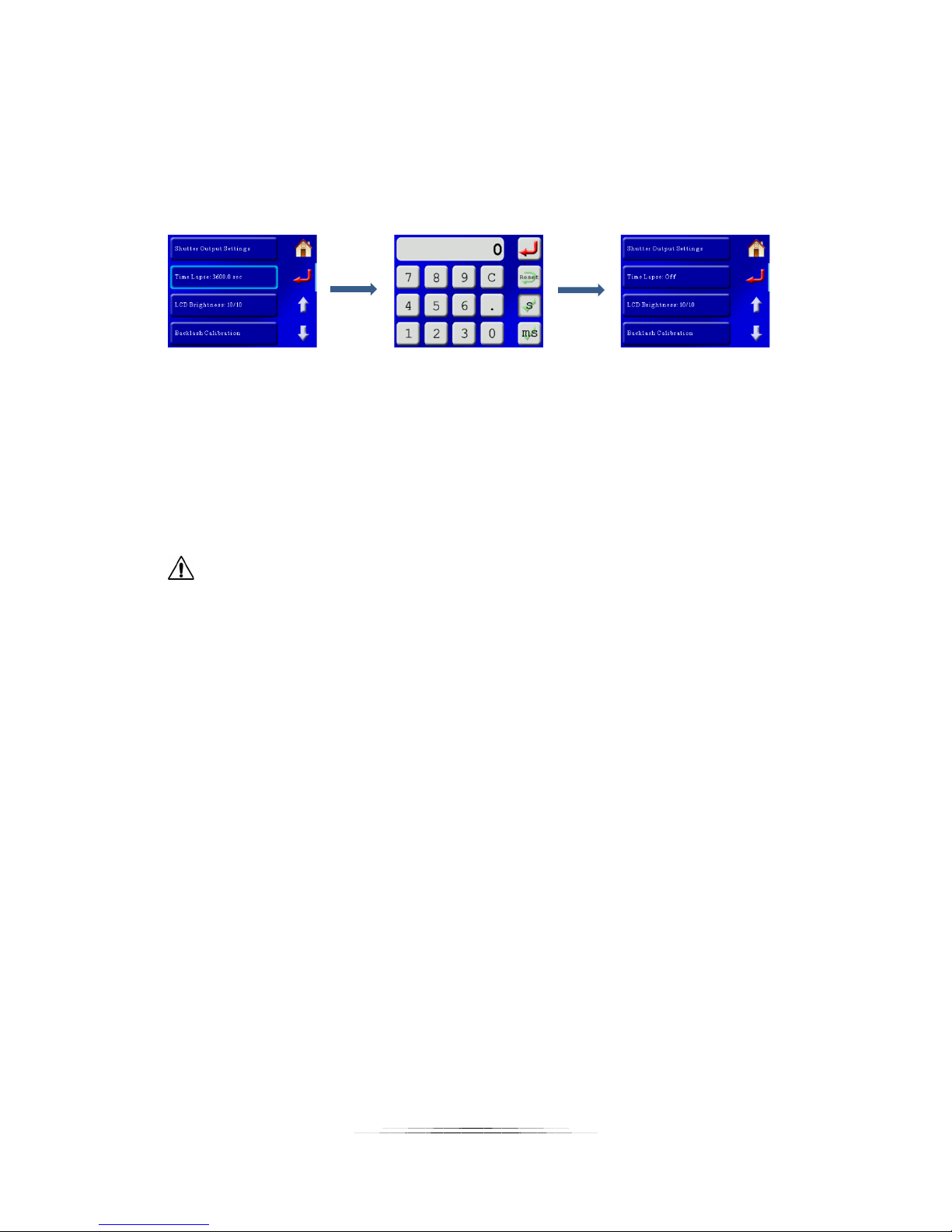
This way you will know which axis is busy and which ones are waiting to start – handy for X-Y-Z
stacking that may take quite some time to complete.
To exit the Time Lapse screen just touch the display. The next time you start an operation the
“Time Lapse” screen will re-appear. To prevent Time Lapse from starting you need to set the
interval to zero from the settings screen:
Note: If the “Time Lapse” time is faster than the time it takes to complete a task it will skip that
time lapse event and wait for the next interval (You’ll miss that opportunity). Therefore, you
should make sure that the “Time Lapse” time is at least as long as the duration it takes for the
current task to complete. The interval may be adjusted from one second up to 24 hours.
CAUTION: Time lapse mode will potentially cause the un-attended operation of the
equipment. Use caution to avoid situations where someone may be seriously hurt or something
seriously damaged due to this feature.
8.7 LCD Brightness
This setting adjusts the brightness of the LCD. Valid numbers are from 1 – 10. See section “8.15
- LCD Power Save” for turning off the LCD completely when not in use.
8.8 Backlash Calibration
Backlash calibration is a simple process to fine-tune the backlash for the macro rail, rotary table,
or slider. In this example we will walk through calibrating the macro rail.
StackShot 3X ships with a default backlash setting that is based off of a sample of rails. Due to
manufacturing tolerances and your specific application, the backlash may need to be adjusted.
To calibrate a device attach it to the StackShot 3X controller and press the “Backlash
Calibration” button. In this example we will calibrate a macro-rail attached to the X-axis:
94
Page 95
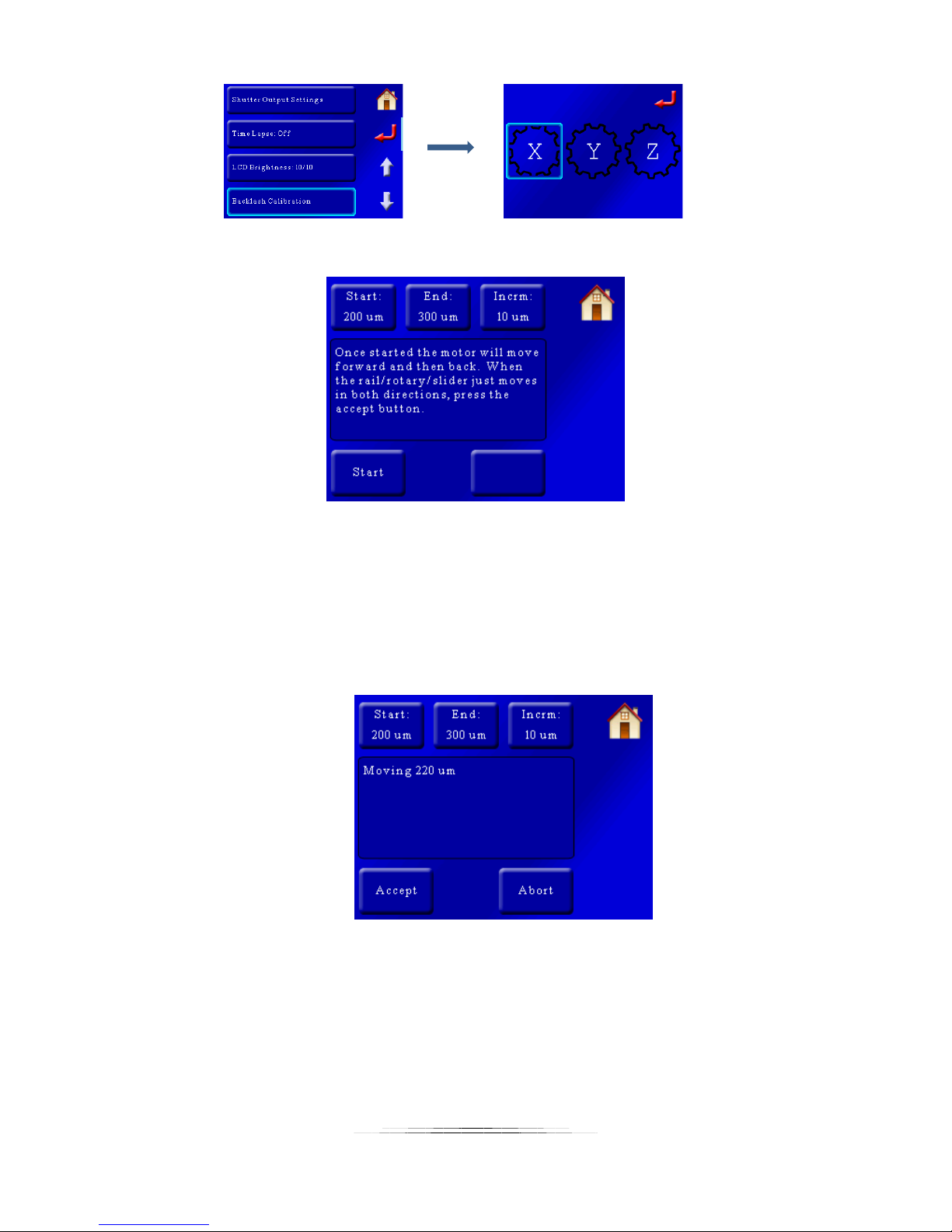
That will bring up the following screen:
There are three buttons at the top: “Start”, “End”, and “Incrm”. What happens during backlash
calibration is that the motor will rock back and forth and then pause. It will then add the
increment and repeat. You will have to either set up a micrometer to touch the rail or for more
course calibration you can visually look for the rail to move. The “Start” value is how far the rail
will start moving, and then get incremented by “Incrm” until it reaches the “End” value.
During the calibration you will see the following screen:
Once you detect the equipment is moving press the “Accept” button. Your backlash value will
be set to this new value!
95
Page 96
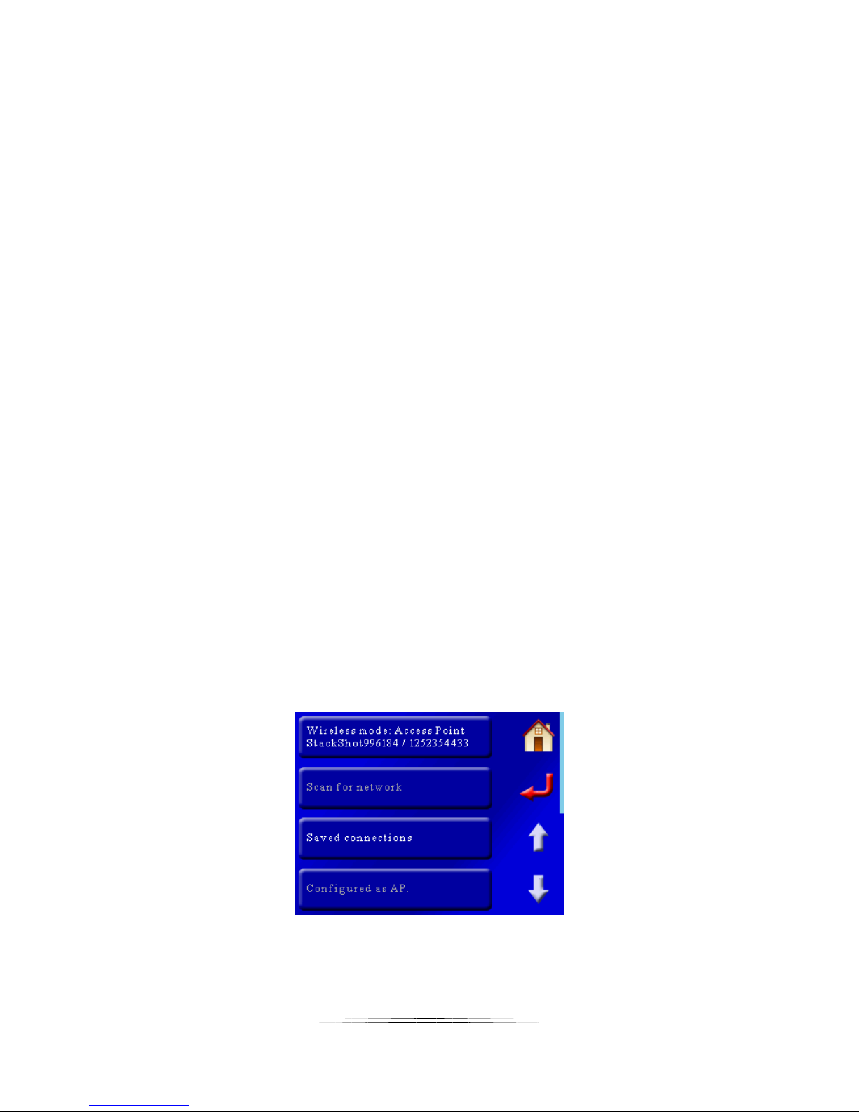
8.9 Axis Linking (Focus Stacking only)
This setting will help you link more than one axis together to perform a task. It is only available
in focus-stacking mode. Once the “Axis Linking” button is pressed a helper will ask you
questions for setting up the link. This will let you perform complex stacks. Usually you can use
one of the existing modes in stacking like Stack/Rotate or X-Y Scan to meet your requirements
but occasionally some people have one of those “different” applications that we just didn’t
consider. Axis linking will let you loop between different axes with mixed stacking modes. It’s
extremely flexible but is best to be avoided due to its potential complexity.
8.10 Wireless Config
This menu lets you configure the wireless settings for StackShot 3X. The controller supports
802.11 a/b/g/n using a variety of security protocols. In this section we’ll refer to a computer,
tablet, or camera as “your device”.
8.10.1 Wireless Mode
There are two modes for wireless connectivity:
1. Access Point: Other devices connect up to StackShot 3X (such as your computer, tablet, or
camera). Think of StackShot 3X as behaving like your wireless router in your home.
2. Client: StackShot 3X connects to another device (home router, WiFi hot-spot, or camera)
To change the mode you touch the top button that says “Wireless Mode”. It will change
between “Access Point” and “Client”.
8.10.1.1 Wireless Mode: Access Point
When StackShot 3X is set as an access point you will see a screen similar to this:
“Wireless mode: Access Point”, and below it are two pieces of information. You will see
“StackShotXXXXXX” where “XXXXXX” is a unique ID for your StackShot. This is what you will see
96
Page 97
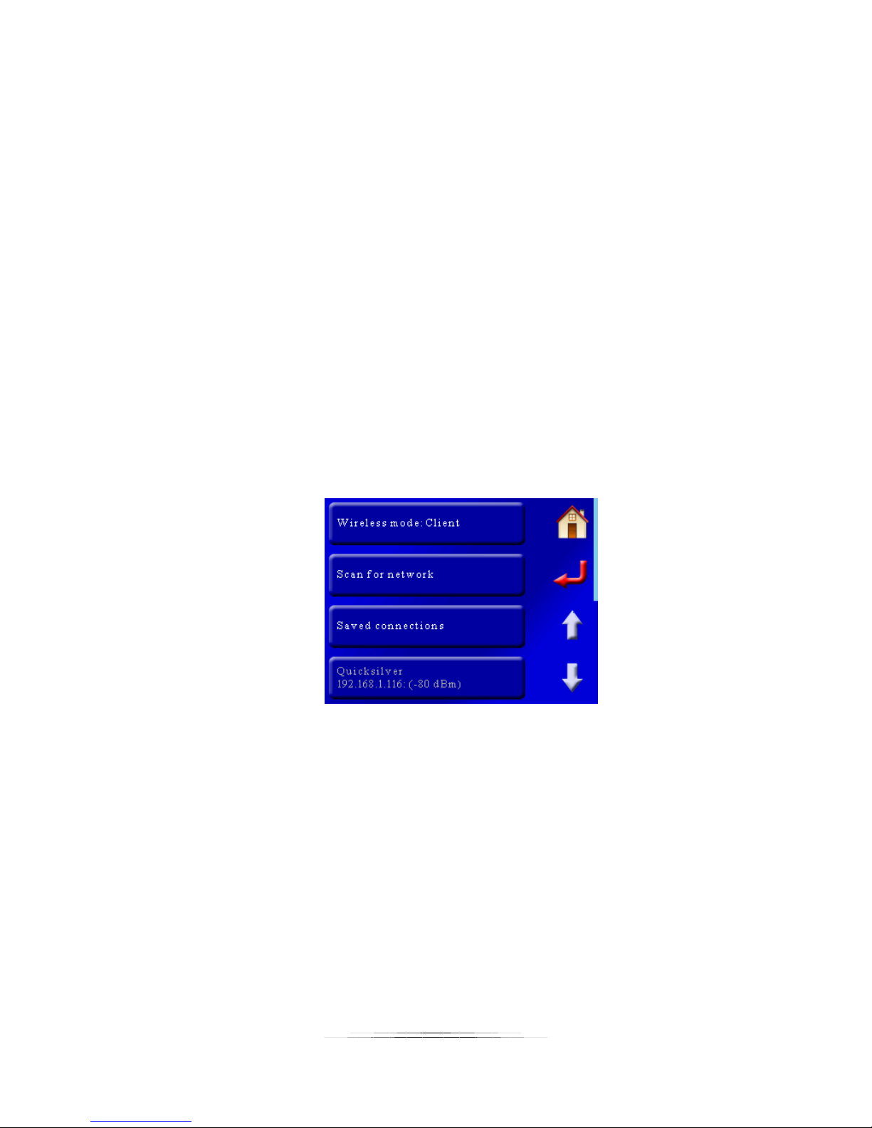
when your device looks for wireless networks. After the StackShot ID you will see a “/” followed
by a sequence of numbers. These numbers are the password for connecting to StackShot. In
the above example the name you will see when looking for wireless access points would be
“StackShot996184”, and the wireless Password/Passphrase is “1252354433”.
As you can see “Scan for network” is grayed out since that is only available when in client mode.
The last box is usually for information on a connection. This is also grayed out since it is
configured for an access point.
8.10.1.2 Wireless Mode: Client
“Client” indicates that you plan on connecting up to another network. Initially you will have to
scan for a network to “find” a router or access point to connect with. Once successfully
connected your connection will be saved for future use under the “Saved Connections” button.
Note: StackShot 3X does not automatically connect to saved networks. This is done to conserve
battery power. You will have to select the desired network each time you wish to connect to it.
Once connected to a network you will see the bottom button of the display grayed out. It will
indicate the name of the router/access point you are connected to along with StackShot’s local
IP address:
In this case StackShot 3X is connected to a router called “Quicksilver”, and the controller’s IP
address is 192.168.1.116.
8.10.2 Scan for network
This button will start scanning for new wireless networks. It is only available when the “Wireless
Mode” is set to “Client”. The scan will take approximately 10 seconds to complete and will bring
up a list of available networks:
97
Page 98
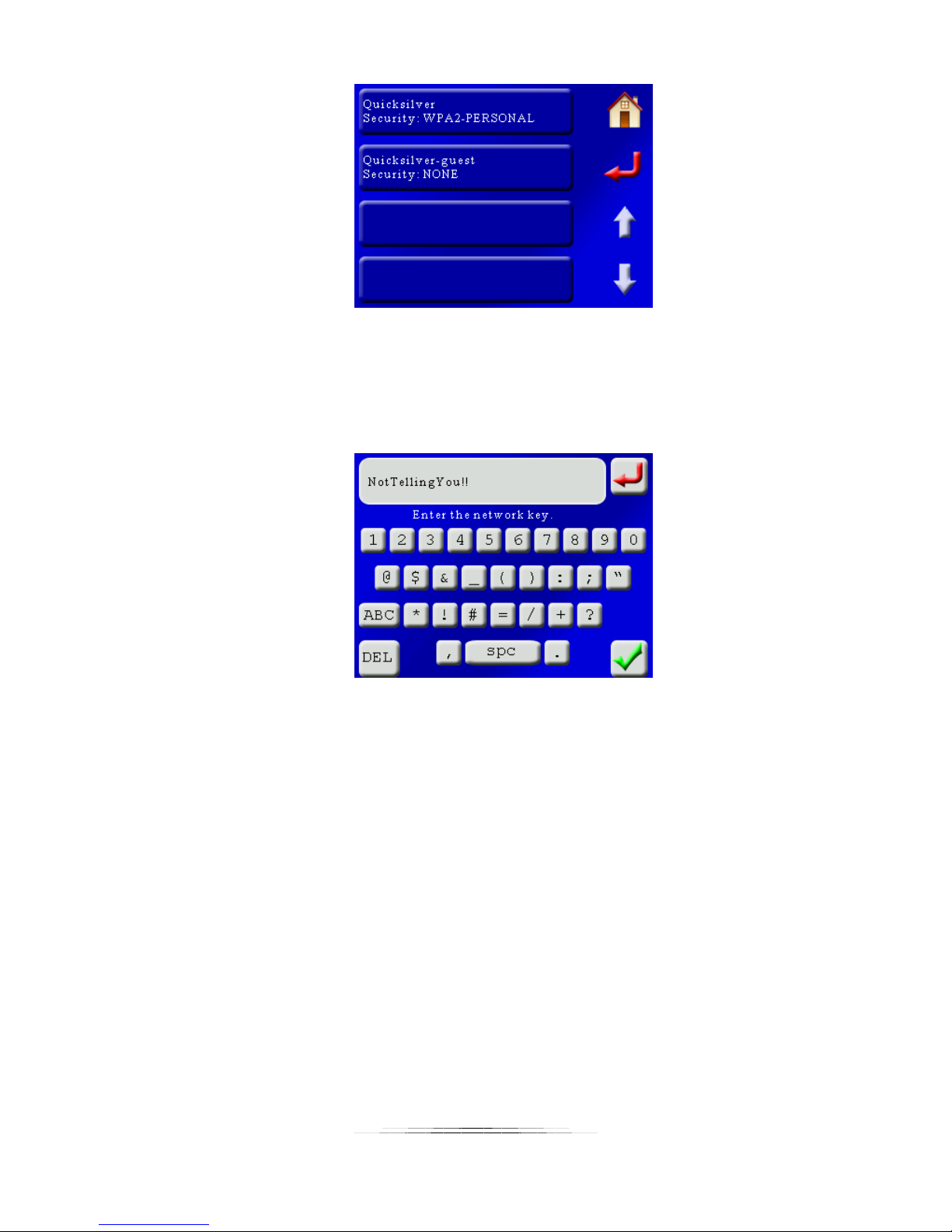
In this case there are two networks available. The security setting for the router is displayed
below the name of the router/access point. To connect to this network touch the name of the
router desired.
If the router requires a password/passphrase, the QWERTY screen will show up:
Enter the password for your router and then press the green checkmark.
If the connection is successful it will be saved for future use. See section “8.10.3 – Saved
Connections“ for connecting to saved networks.
Note: Scanning for a network will disconnect any active connection.
8.10.3 Saved Connections
StackShot 3X lets you save up to four wireless connections for future use:
98
Page 99
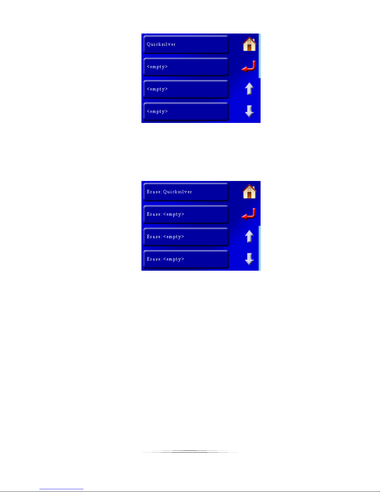
To connect to a network in the future, press the “Saved Connections” button, and the above
screen will show up. Touch the button that corresponds to the network you want to connect to.
If you would like to erase a previously stored network press the down arrow to get to the next
page:
On this page you can press the “Erase” button on the network you would like to remove.
8.10.4 Regulatory Domain
Regulatory domain means “which government agency handles radio waves”. The default is
“FCC”, which works properly within North America. Available options are:
1. FCC -- North America
2. ETSI -- Europe
3. TELEC -- Japan
You may wonder why this matters. 802.11 has several different frequency channels that it uses
and globally governments couldn’t agree on a universal standard. So some countries exclude
certain channels. If you are in Europe, channel 12 is valid, but in the U.S.A. it is not. Therefore,
please make sure you select the proper domain for your country.
99
Page 100
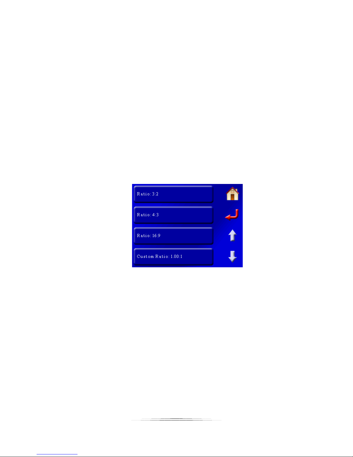
8.10.5 AP Security
“AP Security” refers to what security method StackShot 3X should use when configured as an
“Access Point”. It defaults to using “WPA2” security and encryption. Older network cards may
not support the enhanced security of “WPA2”. If you press the “AP Security” button the
security will toggle between “WPA2” and “Open”. “Open” indicates that there is no security or
password/passphrase required to connect to StackShot 3X. The downside to “Open” is that
anyone can connect to your controller.
8.11 View Log
This is a temporary log file containing information that may help Cognisys track down a problem
you are having. Don’t panic if you see warnings and errors in here! Evil happens – the
important thing is that the evil is managed!
8.12 Aspect Ratio
This is the aspect ratio of your camera. The default is “Ratio: 3:2”:
Available ratios are 3:2, 4:3, and 16:9. You also have the option to enter a custom ratio.
The aspect ratio is only used for the Panoramic modes – See section “6.1.2 – Setting the aspect
ratio“ for details on how this setting is used.
8.13 Panoramic overlap
This is the amount of guaranteed overlap for Panoramic modes (See section “6.1.3 – Setting the
overlap“ for details on how this setting is used). It is expressed in a percent of your camera’s
field of view. Chances are that you will have more overlap than this value but this is the
guaranteed minimum. To adjust the value touch the “Panoramic Overlap” button and enter the
percent desired. Valid values are 0 – 80%.
100
 Loading...